

Page 1
Operation GSK928TC Turning CNC System
OPERATION
I. Introduction
GSK928TC Turning CNC system, realized high-speed ìm-precision control with highspeed CPU and CPLD
as its control part, has 320×240 lattice graphic LCD with friendly Chinese/English menu, fullscreen edition,
realtime tool-trail graphic display. It runs the user program with international standard CNC language-ISO code. It
is widely suitable for response stepmotor driver, complex stepmotor driver and servomotor driver. By the
programming, it makes the machine to cut cylinder, end, slot, taper, arc, thread and so on.
II. Specification
2.1 Controllable axes 2 axes (X Z axis)
2.2 Linkage axes 2 axes (X Z axis)
2.3 Min. enactment unit 0.001 mm
2.4 Min. move unit X axis 0.0005 mm Z axis 0.001 mm
2.5 Max program travel 8000.000 mm
2.6 Max move speed 15000 mm/min
2.7 Cuting speed 5-6000 mm/min
2.8 User Data Storage 24KB
2.9 Max program numbers 100
2.10 Graphic LCD 320 240 lattice
2.11 Communication interface standard RS-232
2.12 Controllable tool positions 4 extendable to 8
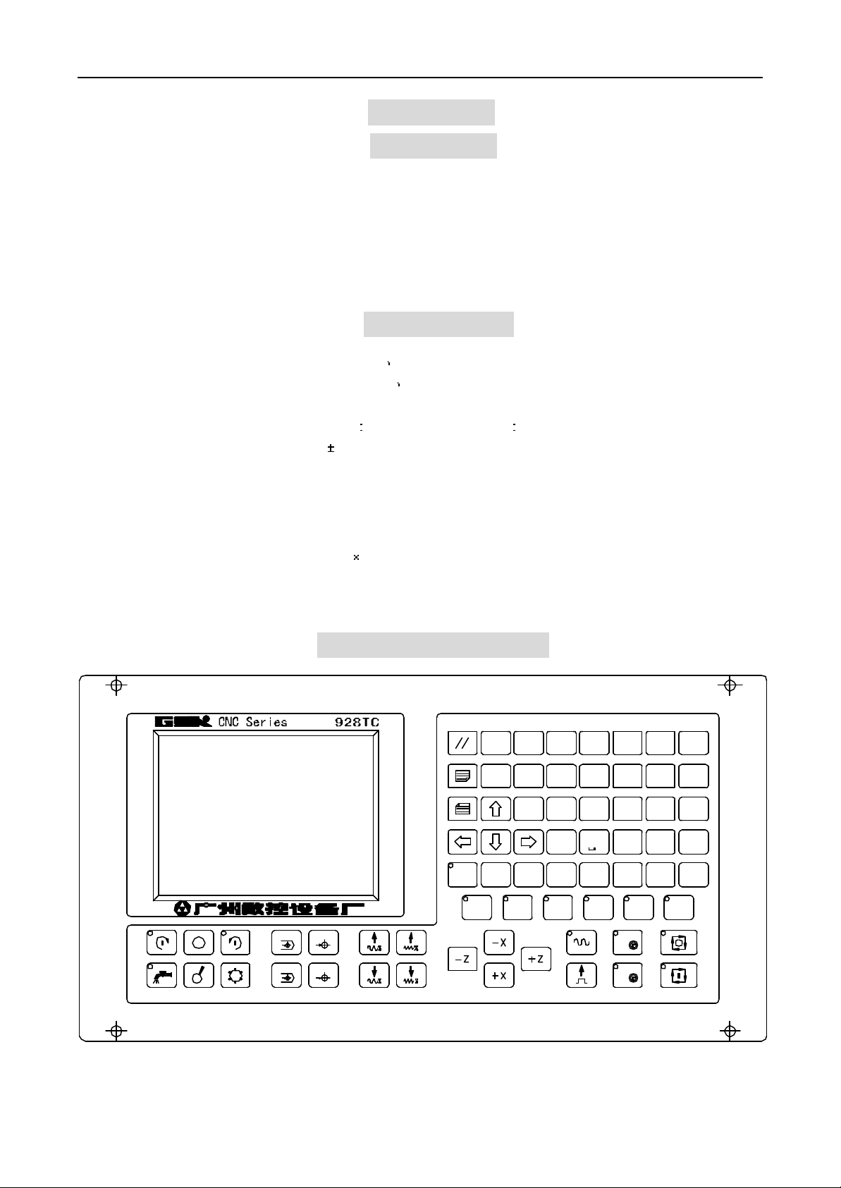
III. OPERATION PANEL
MG
X Z 7 8 9
RIE
DLN
改写
REW
自动
AUTO
WU
K
/P
删除
参数
PAR
1
.
退出
ESC
X
Z
刀补
OFT
2 3
0 -
输入
INPUTDEL
诊断
DGN
654
回车
ENTER
TS
F
空运行
单段
SINGLE
手动
JOG
单步
STEP
DRY
编辑
EDIT
X
X
Z
H/L
Z
GSK CNC Equipment Company 1
Page 2

Operation GSK928TC Turning CNC System
Instructions of the GSK928TC turning CNC system panel:
3.1 LCD display: 320x240 lattice distinguishability, the communication interface between the machine and
human.
3.2 Digit button: input all kinds of data (0~9).
3.3 Address button: input letters, addresses, segments and programs.
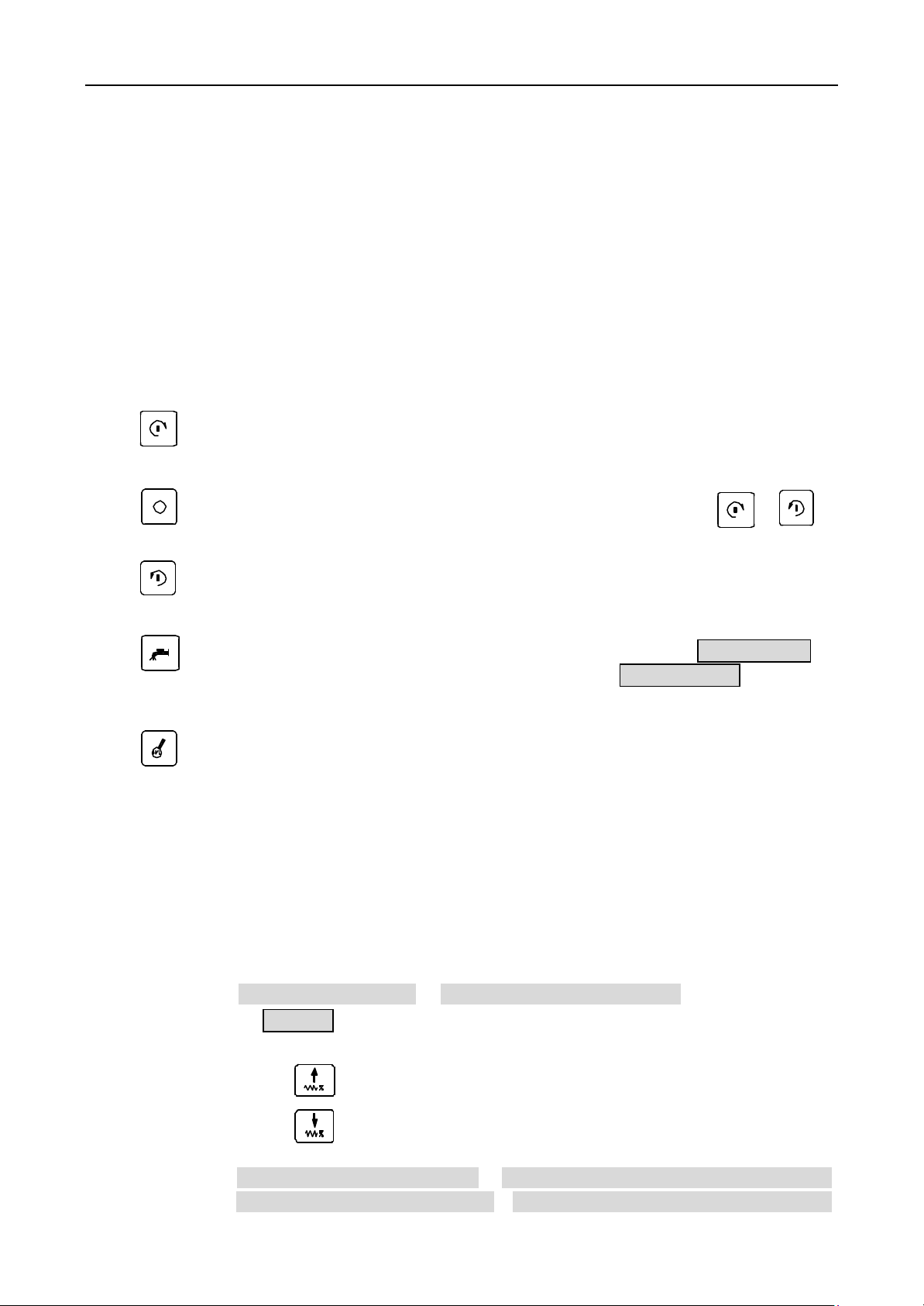
3.4 Funtion button: this system was designed with the visualized symbol function button according to the
standard ‘the visualized symbols of CNC machine tool’ as follows:
Fast multiple increase button: Increase the multiple of the max move speed on JOG mode. Increase
the speed multiple of dictate G00 on AUTO mode.
Fast multiple decrease button: Decrease the multiple of the max move speed on JOG mode.
Decrease the speed multiple of dictate G00 on AUTO mode.
Feed multiple increase button : Increase the feed speed multiple on JOG mode. Increase the speed
multiple of dictate G01 on AUTO mode.
Feed multiple decrease button : Decrease the feed speed multiple on JOG mode. Decrease the speed
multiple of dictate G01 on AUTO mode.
X
X axis returnning to program reference point Button: It is valid only on the JOG/AUTO mode
Z
Z axis returnning to program reference point Button: It is valid only on the JOG/AUTO mode
X
X axis returnning to machine reference point Button: It is valid only on the JOG mode
(Whether the machine reference point is valid can be defined by the MZRO bit of the parameter P12)
Z
Z axis returnning to machine reference point Button: It is valid only on the JOG mode
(Whether the machine reference point is valid can be defined by the MZRO bit of the parameter P12)
空运行
Dry run button: When the dry run is selected on AUTO mode, neither the coordinates of the
Dry
machine move nor the S , M, T functions run if the program starts. On EDIT mode, it moves the cursor
to the the first character following this line number
单段
Single button: to select the single segment run/continuum run on the AUTO mode
Single
编辑
Edit button: to select the edit operation mode
EDIT
手动
JOG button: to select manual operation mode
JOG
AUTO button: to select auto operation mode
自动
PAR button: to select parameter operation mode
参数
刀补
OFT button: to select tool offset operation mode
DGN button: to select diagnosis operation mode
诊断
2 GSK CNC Equipment Company
Page 3

Operation GSK928TC Turning CNC System
3.5 Edit button /State-selection button
改写
Rew
Switch between the inset and rewrite ways on the edit mode.
删除
Del
Delete the figure, letter, segment, or whole the program.
退出
Esc
Cancel the local inputing data or escape from local state.
输入
Input
Input all kinds of data, select the needed edition, run the program or establish the new user
program.
回车
Enter
Confirm the input.
Page up to searches the program or parameter on the edit/parameter/tool offset mode, or
increase the brightness to the display on the other modes.
Page down to searches the program or parameter on the edit/parameter/tool offset mode, or
decrease the brightness to the display on the other modes.
Move the cursor up on the edit/parameter/tool offset mode
Move the cursor down on the edit/parameter/tool offset mode
Move the cursor ahead on the edit/parameter/tool offset mode
Move the cursor backwards on the edit/parameter/tool offset mode
3.6 Loop start button and Feed-hold button
Start the program to run on the AUTO mode, pause on the operation
Loop start button Start the program to run automatically on the AUTO mode.
Feed-hold button The motors slow down to pause on the AUTO or JOG mode
3.7 Manual axis-control button
Move the selected axis along the moving direction on the JOG mode
Move the x axis along negative direction on JOG mode.
Move the x axis along positive direction on JOG mode.
Move the z axis along negative direction on JOG mode.
Move the z axis along positive direction on JOG mode.
GSK CNC Equipment Company 3
Page 4

Operation GSK928TC Turning CNC System
Fast move/Feed button Switch between fast move speed and feed speed in JOG.
JOG step select button Select the step of the monostep feed or handwheel feed in Single
feed/handwheel feed mode.
X axis Handwheel select button Select handwheel to control X axis when this system
X
assembled the handwheel.
Z axis Handwheel select button Select handwheel to control Z axis when this system
Z
assembled the handwheel.
单步
Single/JOG mode Switch between the manual monostep and jog mode.
3.8 Manual Toolchange and Assistant Functions Buttons
Select the next tool position directly and manage the machine to run all assistant function. The buttons are
defined as follows:
Spindle stop button The spindle stops running when push this button.
Coolant button Switch the coolant on/off
Tool change button Select the next tool postion when push this button once.
Remark: All above buttons are efficient in JOG/AUTO mode when X,Z axes stop. But onlythecoolant
Step
Spindle positive rotation button The spindle rotates counter-clockwise (watch from the motor
shaft) by pushing this button.
Spindle negative rotation button The spindle rotates clockwise (watch from the motor shaft) by
pushing this button.
Spindle shift button Select the spindle speed when the main spindle motor has more then one
step speed (not more then 16 steps) and the machine has the control loop.
button is efficient in running.
3.9 Reset Button
System reset button All axes will stop when this system resets, and all output of assistant
functions are inefficacy, the machine stops running and return to the initial status of
electrification.
3.10 State indicator
Indicate the current running state of this CNC system. There have 15 function buttons with LED
indicators. The corresponding function of this button is availability when the LED indicator lights.
4 GSK CNC Equipment Company
Page 5
Operation GSK928TC Turning CNC System
IV. SYSTEM OPERATION
In this chapter, details the all functions modules of this GSK928TC turning CNC system and their operations
and notices. Please read this chapter carefully before start the machine with this system.
4.1 System turn on/off
There has not the power switch on this system. To avoid the power concussion, install the power switch for
this system according to the actual state of the machine.
Turn on as follows:
1 Power on the machine’s electrical source first.
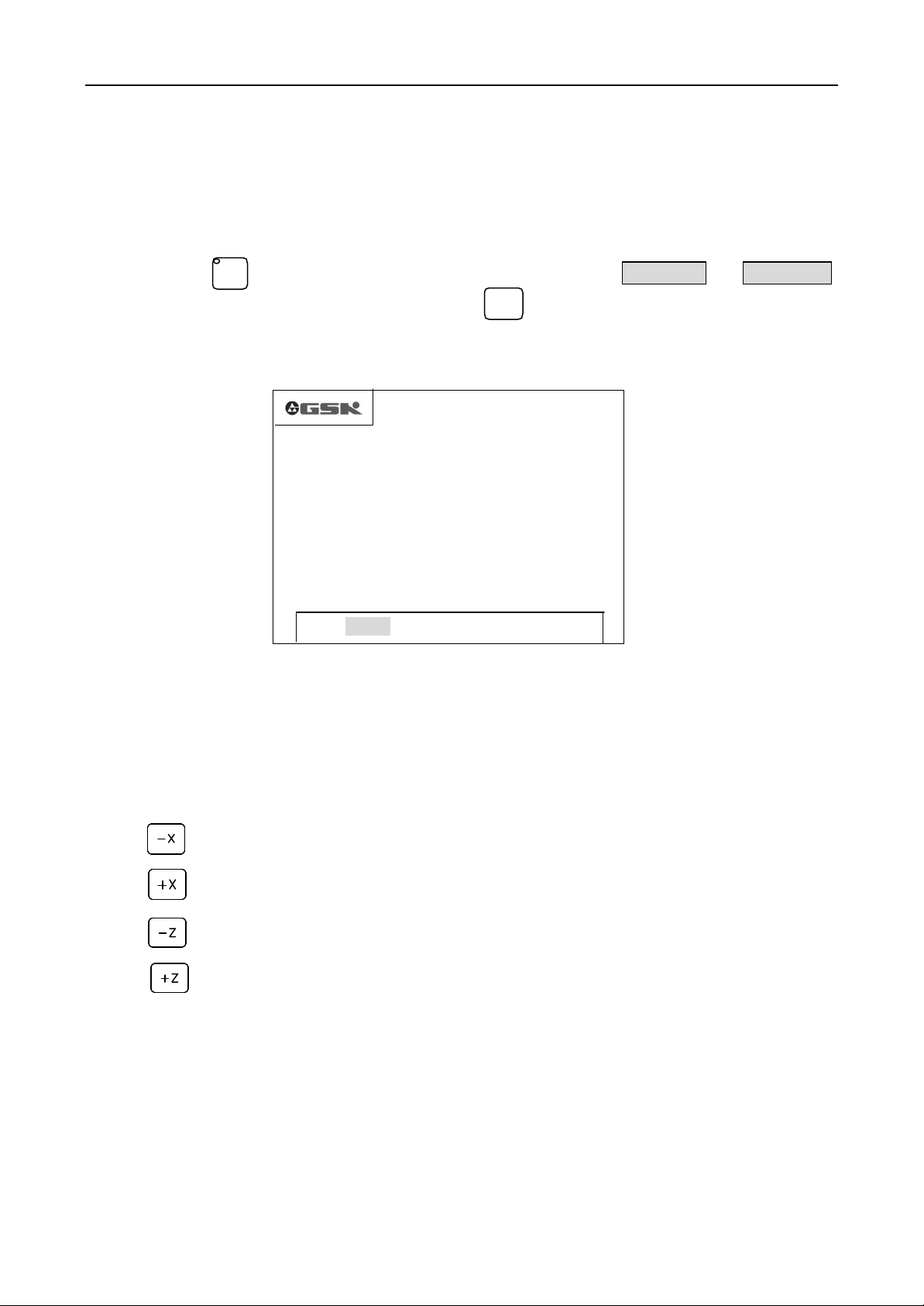
2 Put through the system’s switch if there has, and then the system appears as picture1. Keep pushing any
button with the exception of the buttons , , when it is displaying the picture1, the
system will display the version number of this system. After release the button, the system enters the
normal run state.
Turn off as follows:
1 Cut off the system’s switch if there has.
2 Power off the machine’s electrical source.
CAUTION: When the system powers on first, it is needed usually to operate as follows:
1. Initialize the system’s parameter section such as:
Push the button and at the same time . First release the button , after 3 seconds, release the
button , the system was initialized. At then, all the parameters of tool offset are 0, all the parameters of the
machine reset as initial value. Please consult the offset and parameter instruction in this manual.
2. Measure the reverse transmission clearance of X, Z axes, and enter system parameters P07 and P08. Please consult
the parameters instruction in this manual.
3. Define the DIRZ and DIRX in parameter P11 according to the electric design and motor direction of the machine.
4. Adjust the parameters P05, P06, P17~P22 to let the machine run reposefully and availably according to the
machine’s load.
删除
Del
删除
Del
广 州 数 控
Picture1. System initial display
4.2 System run mode selection
Select or change the run mode of GSK928TC by push button directly. It is maneuverable, convenient and
directviewing.
If no one of button is pushed, this system displays the picture1 circularly when it powers on. If any button
except button was pushed, this system will return to the mode of last power off. If power on with pushing
button or push button and button at the same time, release first, a moment later,
releases the button , this system will enter the MANUAL mode.
退出
Esc
退出
Esc
GSK CNC Equipment Company 5
退出
Esc
Page 6
Operation GSK928TC Turning CNC System
4.3 EDIT Mode
On EDIT mode, input or edit the cutting programs and their contents by pushing buttons on the keyboard. All
the cutting programs can be built, selected or deleted by the keyboard. And the contents of the selected cutting
program can be edited such as inset, amend, deleted and so on. And the RS232 communication port of this system
can be connected to the serial port of the current pc, so the cutting program can be exchanged between this system
and the current pc.
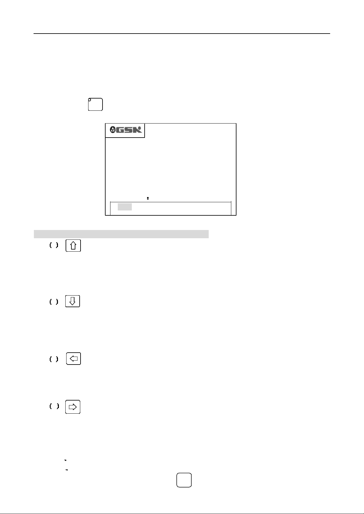
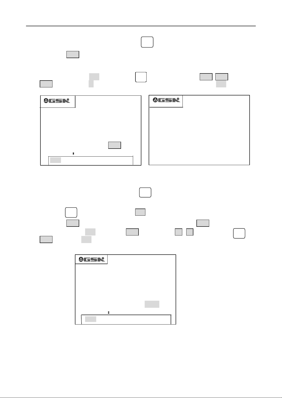
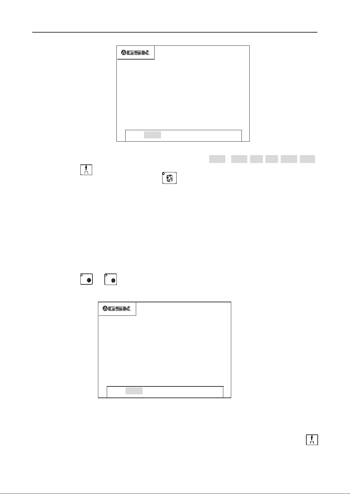
Push the button to enter EDIT mode, this system appears the names of all stored program, bytes of the
编辑
EDIT
current programs and the spare capability of this system as follows:
%00 %02 %03 %04 %10
PROG. NO. 05 FREE BYTE 15750
EEDDIIT
EDIT %02 0223
T MANU AUTO PARA OFFT DIAG
Picture2 edit mode
On the EDIT mode, the definitions and usage s of the buttons
1 Upmove cursor button
The cursor moves to the position of the first charater after front program row number when push this
button once.
Keep pushing this button, the cursor continues to move above until the cursor arrives at the first program
row or the button is released.
2 Downmove cursor button
The cursor moves to the position of the first charater after next program row number when push this button
once.
Keep pushing this button, the cursor continues to move down until the cursor arrives at the last program
row or the button is released.
3 Leftmove cursor button
The cursor moves to the position of the front charater when push this button once.
Keep pushing this button, the cursor continues to move left until the cursor arrives at the first charater or the
button is released.
4 Rightmove cursor button
The cursor moves to the position of the next charater when push this button once.
Keep pushing this button, the cursor continues to move right until the cursor arrives at the last charater or the
button is released.
CAUTIONS: Cursor – Pompt of Local editing position. There have two forms:
A On inset mode, the cursor is a line segment under the charater.
B On rewrite mode, the cursor appers such that the charater is displayed with highlight and color inverse.
The cursor forms can be switched by button .
6 GSK CNC Equipment Company
改写
Rew
Page 7
Operation GSK928TC Turning CNC System
编辑
once, and the cursor forms will switch accordingly. On inset mode, the cursor is a flashing line segment. On rewrite
mode, the cursor appers such that the charater is displayed with a flashing highlight square charater.
pushing Input button, and inputing the serial number with two digits.
改写
5 In set/rewrite Button
Rew
Push the Inset/rewrite button once, then the input modes will switch between inset and rewrite mode
输入
6 Input button
Input
To establish a new program, select a existent program or delete a existent program or all programs by
7 Pageup button
Push this button to display the front page when search serial numbers list or program contents,
8 Pagedown button
Push this button to display the next page when search serial numbers list or program contents,
U
9 Double-functions button
W I
/
E
K
P
D R
N L
Each button can be defined two functions. Push these buttons once, the system performs the first
function: U, W, I, K, D, and R. Push these button twice in series, the system performs the second functions: /,
E, P, N, L, and . If push these button continuously, the system switches between the two functions. ‘/’ is
newline prompt, ‘ ’ is blank.
4.3.1 Search the cutting program list
On EDIT mode, list all the nemes of the cutting programs in the system’s storage, the cutting program
numbers and the spare capability.
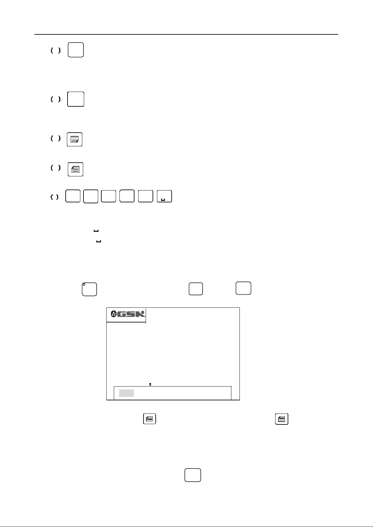
Push button on EDIT mode, or push button or button in editing, the system displays
as PICTURE3.
EDIT
退出
Esc
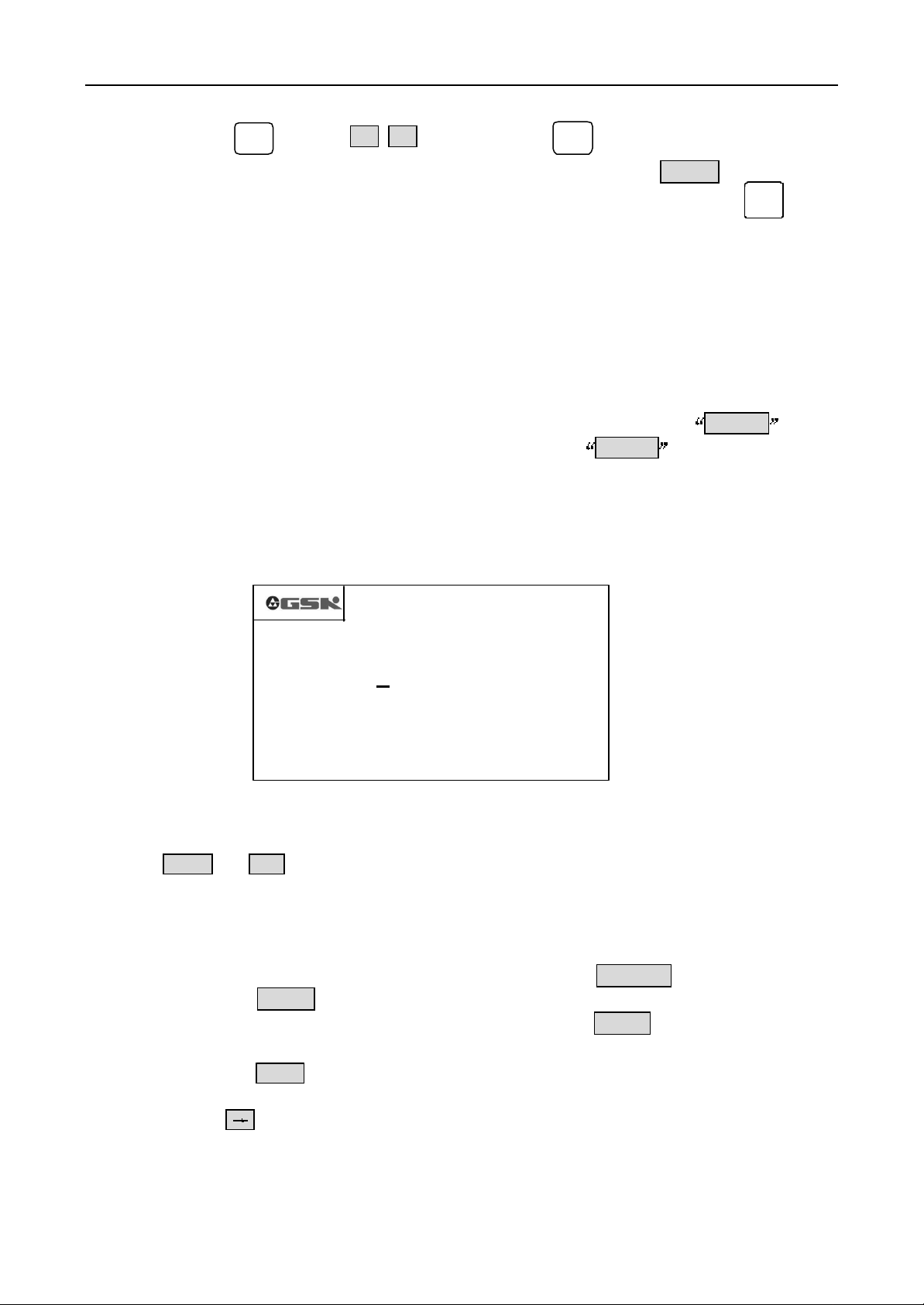
%00 %02 %03 %04 %10
PROG. NO. 05 FREE BYTE 15750
PICTURE3 Program search, establish, select, delete and etc.
EEDDIIT
EDIT %02 0223
T MANU AUTO PARA OFFT DIAG
输入
Input
40 pcs program names can be displayed once. If the displayed program names are more then 40 pcs, the
display will be paging. Push the button , it displays the next page. Push the button , it displays the
front page.
4.3.2 Cutting program’s establish, selection, deletion, rename, and copy
The establish, selection, deletion, rename, and copy of cutting program can be processed on the program list
display state or program content display state
On the program list display state, push the button , the system displays ‘INPUT PROG. NO. %’ to
prompt the program’s number.
GSK CNC Equipment Company 7
输入
Input
Page 8
Operation GSK928TC Turning CNC System
05 FREE BYTE 15750
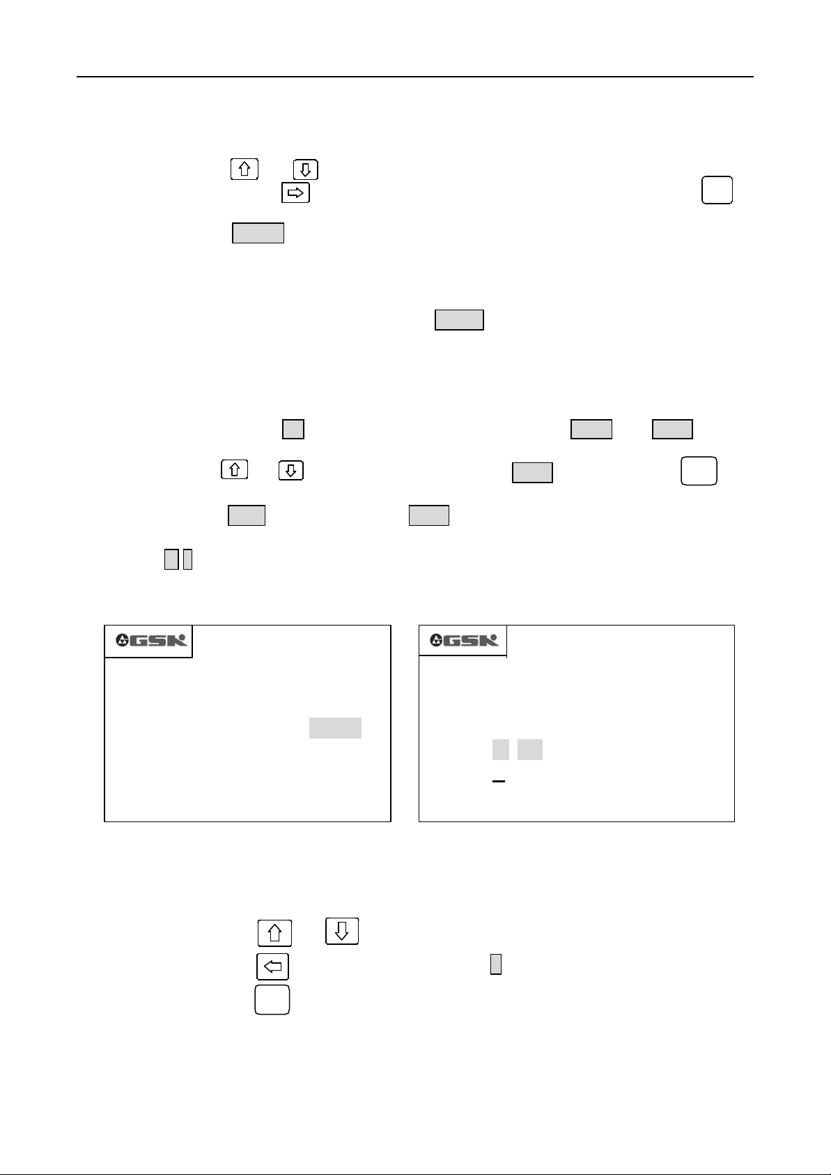
4.3.2.1 Establish a new cutting program
1. On the program list display state, push the button .
2. Input the 2 bits program number that isn’t existent in the system as PICTURE 4.
输入
Input
3. Push button Enter
4. The new program is established, the system enters the program content edit state automatically.
Ex. Establish the program%20, push the button then input digit buttons 2 0 , and put the
输入
Input
button Enter. New program %20 is established, and the system turns to edit the new program %20 automatically
as PICTURE 5.
%00 %02 %03 %04 %10
INPUT PROG. NO. %20 Enter
PROG. NO. 05 FREE BYTE 15750
EEDDIIT
EDIT %02 0223
N0000 _
T MANU AUTO PARA OFFT DIAG
EDIT %20 0007
PICTURE 4 INPUT THE PROGRAM NUMBER PICTURE 5 ESTABLISH A NEW PROGRAM
4.3.2.2 Delete the cutting program
1. On the program list display state, push the button .
2. Input the program number that needs to be deleted.
3. Push button , then the system displays DEL?
删除
Del
4. Push button Enter to delete the program, or not, push any button except for Enter to escape.
Ex. Delete the program %03 , Push button Enter, input the digits 0 , 3 , then push button and
button Enter, the program %03 is deleted from the storage of this system as PICTURE 6.
%00 %02 %03 %04 %10
INPUT PROG. NO. %03 DEL?
PROG. NO.
EEDDIIT
EDIT %02 0223
T MANU AUTO PARA OFFT DIAG
PICTURE 6 DELETE THE CUTTING PROGRAM
输入
Input
删除
Del
8 GSK CNC Equipment Company
Page 9

Operation GSK928TC Turning CNC System
4.3.2.3 Select a cutting program
1. On the program list display state, push the button .
2. Input the program number that needs to be selected.
输入
Input
3. Push button Enter
4. Select the cutting program and the system displays the program contents, and it can be edited.
Ex. Select cutting program %01. Push button , input the digits 0, 1 then push button ENTER, the
输入
Input
program %01 is selected as PICTURE 7.
N0000 G0 X0 Z0
N0010 G1 X4.80 Z9.6 F500
N0020 G0 X0.0 Z00
N0030 G4 D2
N0040 M20
EDIT %01 0082
PICTURE 7 SELECT A CUTTING PROGRAM
Cautions:
1. This NC system automatically establishes and selects a new cutting program %00 if there has not any cutting
program or program content when the system powers on first.
2. After a cutting program is selected, it will stands in current state until the other program is selected, even if the
system powers off.
4.3.2.4 Output of the cutting program
Output the cutting program stored in the system’s storage to the external pc.
1. Connect the communication cable between the system and external pc when the system powers off.
2. The system powers on and enters the EDIT mode.
3. Select the cutting program that need to be output (It doesn’t need to be selected if the program to be sent
out is current).
4. Push button W, it prompts ‘PREPARE TO SEND ’.
5. Start the GSK928TC communication program in the external pc to the receiving state. (Please refer to the
appendix of the <Operation Instruction of the GSK928TC Communication Program>).
6. Afer the external pc is convinced that it is in the receiving state, push button Enter, the system prompts
‘SENDING…’, and it send the cutting program to the external pc.
7. As soon as the system sends out the program, it prompts ‘SENT OUT’, and then push any button to
return to the EDIT mode.
8. Push button to interrupt the program sending.
退出
Esc
4.3.2.5 Input of the cutting program
Input the cutting program from the external pc to this system.
1. Connect the communication cable between the system and external pc when the system powers off.
2. The system powers on and enters the EDIT mode.
3. Select the cutting program that need to be output (It doesn’t need to be selected if the program to be sent
out is current).
4. Push button R, it prompts ‘PREPARE TO RECEIVE’.
GSK CNC Equipment Company 9
Page 10
Operation GSK928TC Turning CNC System
5. Start the GSK928TC communication program in the external pc to the receiving state. (Please refer to the
appendix of the <Operation Instruction of the GSK928TC Communication Program>).
6. Afer the external pc is convinced that it is prepared, push button Enter, the system prompts
‘RECEIVE…’, and it send the cutting program to the external pc.
7. As soon as the system sends out the program, it prompts ‘RECEIVED’, and then push any button to
return to the EDIT mode.
8. Push button to interrupt the program receiving.
退出
Esc
Cautions:
1. When the cutting program is sent from the external pc to this system, this system makes the program name with
the character string ‘%xx” in the first row. If the name of the received program is same as the stored program,
the name and contents of the received program can’t be displayed. So the stored program with same name must
be deleted first before check the new program.
2.
All the cutting programs can be exchanged as above method between GSK928TC systems. Just operate two
GSK928TC systems with input/output mode.
4.3.2.6 Delete all cutting programs
Delete all cutting program in the CNC system once.
1. Push button on the EDIT mode.
2. Input
3. Push button , then the system display DEL? .
4. Push button , the all programs in storage will be deleted, or not, push any other button to return to
the EDIT mode without any change.
输入
O
删除
Del
回车
by keyboard.
4.3.2.7 Rename the cutting program
Rename the local cutting program.
1. Push button , display % .
输入
Input
2. Input a new program number inexistent in this system, and push button , and then the inputted
改写
program name is instead of the local program number.
Example: Change the file name %00 to %05
Push button and input 0 5 ,then push button to finish the rename.
输入
Input
改写
4.3.2.8 Copy the cutting program
Copy the contents of the local program to another program and the new program will be regarded as the local
program.
1. Pree button , display %,
2. Input the program number inexistent in this system, push button , copy the contents of local
program to the program with the inputted program number, and the new program is regarded as the local
program.
输入
Input
输入
Input
10 GSK CNC Equipment Company
Page 11
Operation GSK928TC Turning CNC System
Example: Copy the contents of the local program %00 to the local program %05
Push button , intput 0 5 ,and then push button to finish copy.
输入
Input
输入
Input
Caution: If the inputted program number existed in the system, the system display EXISTED.Push any button
to escape, then input the other program number inexistent in this system, push button .
回车
Enter
4.3.3 Input and edit the contents of the cutting program
This CNC system automatically runs according to the sequence of the cutting programs inputted by
user. The program consists of some program segments. The segment consists of serial number, dictate, data
and so on. Only correctly input the contents of the cutting program in the light of the cutting technics, the
system can run normally.
The edit model of this system is full screen. The programs are managed as documents.
4.3.3.1 Create the serial number automatically
Every program consists of some program segment. And each segement begans at N**** . After a
new program is built, the system will create the first serial numbe as N0000 . And when push button
Enter after inputted a segment, the system will create the next serial number automatically. The increment of
the serial number in program input is set by the parameter P23. The parameter P23 can create the serial
number with the integer of the 1/4 increment.
Create the serial number of segment as PICTURE 8 (Parameter P16 is 10):
N0000 G0 X0 Z0 <
N0010 G1 X4.8 Z9.0 F500<
N0020 G0 X0.0 Z0.0 <
N0030 G4 D2 <
NOTE: The Enter and Esc in above picture aren’t displayed on the screen
PICTURE 8 SERIAL NUMBER CREATION AND PROGRAM CONTENT INPUT
N0040 M20 <
EDIT %01 0082
Enter>
Esc>
Enter>
Enter>
Enter>
4.3.3.2 The program contents input
Edits of this system is on the full screen mode. The program contents were inputted on the EDIT mode.
1. Setup a new program as Chapter 4.3.2.1;
2. Input the contents of the first program row after the Serial Number
N0000
is displayed;
3. Push the button Enter to end the input of this row after this row was inputted;
4. The next Serial Number is created automatically after push button Enter , then the new row can be
inputted;
5. Push the button
NOTE: Only ahead 40 characters can be displayed in every segment if there has more then 40 characters in the segment.
When push the button once, the displayed characters indent one bit to left. There can’t be more then 255 characters in
one row, or not the inputted contents can be accepted. The 13 segments can be displayed in one screen. The segment will move
up automatically after the segments are more then 13 rows.
Esc
to end the input after the all contents of the program were inputted.
GSK CNC Equipment Company 11
Page 12
Operation GSK928TC Turning CNC System
4.3.3.3 Insert the program segment insert
Insert one segment or more between two program segments.
1. Push the button or to move the cursor to the frontal one in the two segments;
2. Keep pushing the button as far as the cursor arrives at the last character, or push the button to
move the cursor to the last character;
3. Push the button
increment is set by the integer part of 1/4 the parameter No. P16. If the numbers are no enough, the next
segment number can be rewrited artificially;
4. Input the contents of the inputted segment;
5. The segment was inserted, except push the button
NOTE 1: Insert the segment after the last segment, push the button directly, the new serial number will be created
automatically.
NOTE 2: A new segment can’t be inserted in front of the first segment directly. If it is necessarily, only rewrite the first
segment with new segment contents, and then insert the contents of the foregoing first segment thereafter.
For example:
1. Push the button or to move the cursor to the segment
the characters
2. Push the button Enter , a new serial number N0022 was created such as PICTURE 9, and the cursor
points to the first character of the new segment;
3. Input M 3 ;
3. the new segment was inserted as PICTURE 10.
N0000 G0 X0 Z0
N0010 G1 X4.80 Z9.6 F500
N0020 G0 X0.0 Z0.0
N0022 __
N0030 G4 D2
N0040 M20
PICTURE 9 PICTURE 10
The segment M3 needs to be inserted between the segments N0020 and N0030 such as
the Picture 8, operate as follows:
EDIT %01 0089
Enter , a new Serial Number is created between these two segments ( The number
Enter
to input the next inputted segments,
N0020
, then push the button after
Z0.0;
EDIT %01 0091
N0000 G0 X0 Z0
N0010 G1 X4.80 Z9.6 F500
< E nter>
N0020 G0 X0.0 Z0.0
N0022 M 3
N0030 G4 D2
N0040 M20
单步
STEP
单步
Step
4.3.3.4 Delete the program segment
Delet the all contents including serial number of one segment.
1. Push the button or to move the cursor to the segment to be deleted;
2. Push the button to move the cursor at the N of the serial number
3. Push the button ;
4. Whole the segment was deleted.
4.3.3.5 Insert the field in the segment
1. Check if it is on INSERT mode. When it is on INSERT mode, the cursor is displayed as an
12 GSK CNC Equipment Company
删除
Del
Page 13
Operation GSK928TC Turning CNC System
underline. Or not, change the mode by pushing button
2. Push the button or to move the cursor to the character after insert position;
3. Input the contents to be inserted
4. The inputted contents were inserted in front of the character with cursor.
改写
Rew
For example: The character
segment
X
NOTE: Each field (a letter and t he following figures) must be blocked off by the space in the segment.
When input the program, the space can be created automatically. But when insert characters, the field
can’t be identified automatically, so the space must be inputted manually to ensure the integrality
og the program.
N0020 G0 X0.0 Z0.0
and input character
4.3.3.6 Delete the field in the segment
1
needs to be inserted between characters X and O in the
, Move the cursor under the character
1
, Now the segment
N0020 G0 X10.0 Z0.0.
0
after character
Delete the needless fields in the segment
1. Move the cursor to the character to be deleted by pushing the button or
2. Push the button to delete the character at the cursor.
4.3.3.7 Amend the segment’s contents
删除
Amend the segment’s contents with two methods (Insert/ Rrewrite).
In Insert Mode, amend the contents by delete and insert.
1. Move the cursor to the character to be amended by pushing the button or
2. Input the new contents
3. Then delete the needless contents
In Rewrite Mode, amend the character with cursor.
1. Select rewrite mode by pushing the button . (The character with the cursor is
改写
Rew
displayed as highlight square;
2. Move the cursor to the character to be amended by pushing the button or ;
3. The cursor move to the next character after input a new character.
For example: Replace X with U in the segment
N0020 G0 X 0.0 Z0.0
1. Select the Rewrite Mode
2. Move the cursor to the character X
3. Input the character U
Then the segment
N0020 G0 U 0 .0 Z0.0
is displayed.
4.3.3.8 Overleap the segment
If insert the character / in front of the Serial Number N , this segment will be overleapped
to run the next segment when this system runs this program.
1. Select the Insert Mode
2. Move the cursor to the segment to be overleapped, and push the button to move the cursor
to the charater N
3. push the button
N /
twice continuously, the first is insert the character U in front
of the character N ,the second is change the character U to character /
GSK CNC Equipment Company 13
Page 14
Operation GSK928TC Turning CNC System
X 0090. 000
Z 0125. 000
手动
4.4 JOG Mode (Manu Mode?)
In JOG Mode, the movement of the machine ’s slider, the stop and start of the spindle and the
coolant, tool change, return to reference point and mechanic point in X, Z axis and other functions
can be finished by keyboard.When the CHCD bit of the parameter P11 is 1, the actual speed of the
spindle can be displayed. When the CHCD bit of the parameter P11 is 0, the setting speed is
displayed.
Push button to enter the JOG Mode (Manu Mode?). There have
in this mode. Initial mode is JOG mode, push button to switch between JOG and Step Mode.If
the Electric handwheel is assemblied in this system. The handwheel control can be adopted. The
display in JOG mode is PICTURE 11 as follows:
JOG
FEEDRATE 100% SPINDLE STOP
FASTRATE 100% SPDL REV 0000
COOLANT OFF TOOL 1 OFFSET 0
EDIT MANU AUTO PARA OFFT DIAG
PICTURE 11 Manual Jog Feed
单步
Step
MANUAL JOG
MANUAL JOG
and
MANUAL STEP
4.4.1 Jog in JOG Mode
Keep pushing the manual axis move button, the slider of the machine will be continuous to
move along the axis direction that was selected until the button is released. It moves with
the speed preestablished. The Manual axis move buttons are as follows:
Move the x axis along negative direction.
Move the x axis along positive direction.
Move the z axis along negative direction.
Move the z axis along positive direction.
4.4.2 Step feed in JOG mode
In Single Steep Feed, push the manual axis move button once, the slider of the machine moves
one preestablished step along the select direction. Keep pushing the manual axis move button,
the slider will be continuous to move with step until the last step is achieved when the button
is released. Ref. PICUTRE 12.
14 GSK CNC Equipment Company
Page 15
Operation GSK928TC Turning CNC System
X 0090. 000
Z 0125. 000
X 0000. 000
Z 0000. 000
FEEDRATE 100% SPINDLE STOP
FASTRATE 100% SPDL REV 0000
EDIT MANU AUTO PARA OFFT DIAG
MANUALSTEP 0.001
COOLANT OFF TOOL 1 OFFSET 0
PICTURE 12 Single Steep Feed
In Single Step Feed, the step can be defined as 7 grades
Push the button to switch from one kind of step to another orderly.
Note 1: In single step feed, push the button to stop the move of the slider, the unfinished steps
don’t be held . To move continuously, it is necessary to push the manual axis-control button again. The step
in X axis is move value in diameter.
Note 2: The the slider can move after push the manual axis move button only when the external switch of
the spindle and feed-hold is in appropriate state. In feed-hold state, the slider does not move by pushing
the manual axis move button.
Note 3: When the slider is moving in Single step feed, the feed - hold button is changed to the feed-hold
state, the slider will reduce the sp eed to stop, and the unfinished steps don
4.4.3 Handwheel Control Mode
In the handwheel control mode, the move of the slider can be controlled by turning the handwheel.
Push the button or to enter the Handwheel Control Mode and to select the move axis.
For example ( X axis):
EDIT MANU AUTO PARA OFFT DIAG
HANDWHEEL X 0.001
FEEDRATE 100% SPINDLE STOP
FASTRATE 100% SPDL REV 0000
COOLANT OFF TOOL 1 OFFSET 0
0.001 0. 01 0.1 1.0 10.0 50.0
’
t be held.
1. Select the axis to be moved by handwheel, turn the handwheel to move the axis
Turn the handwheel clockwise, the axis moves forward
Turn the handwheel withershins, the axis moves forward
2. The move unit of the handwheel has three grades 0.001,0.01,0.1mm. Push the button
To switch from one grade to the next one. When change between the handwheel control and the
Single Step feed, the move grade keeps the enactment.
GSK CNC Equipment Company 15
PICTURE 13 Handwheel Control
Page 16
Operation GSK928TC Turning CNC System
Note 1: The rev of the handwheel should not be more then 5 rev/second, otherwise the move of slider will not
accord with the scale of the handwheel.
Note 2: In handwheel control, all the functions relatved with axis such as JOG, Reset, relative/absolute
movement are invalid, but the S, M, T ans other assistant functions are available.
Note 3: The handwheel will not work if the external spindle stop button or feedhold button keeps valid.
4.4.4 Manual Feedspeed Selection
In Manual Feed, select the multiple of the feed speed. (It is displayed as FEEDRATE)
The feed multiple increases one grade when push this button once. The max multiplies
is 150%.
The feed multiple reduces one grade when push this button once. The min. multiple is
0%.
Note 1: In Manual JOG or handwheel feed, the feed multiple must be seted exactly before operation.
Note 2: In Manual Step, the feed multiple can be seted in operating.
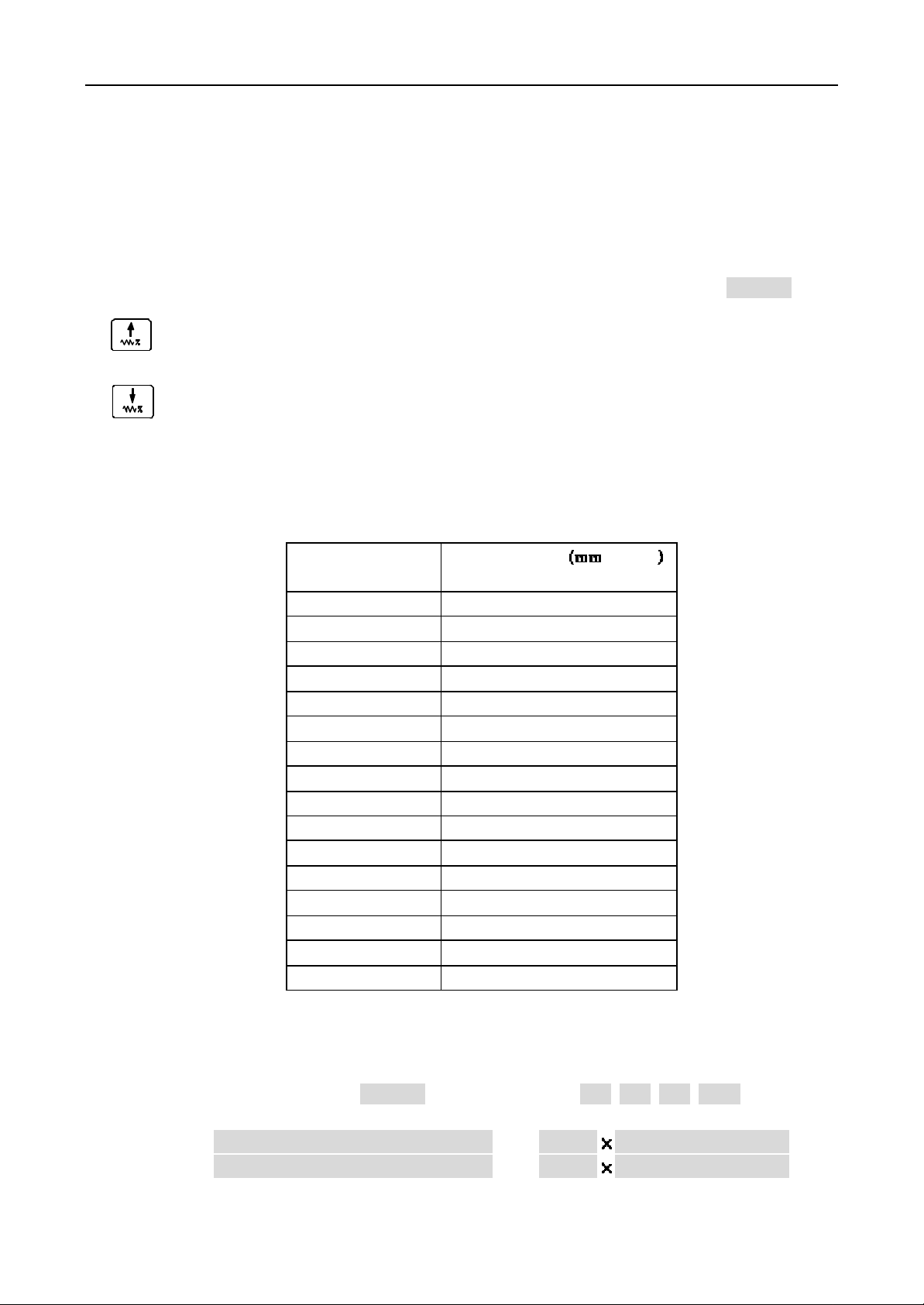
The manual feedspeed multiple is 16 grades from 0% to 150% as follows:
F eed multiple
(FEEDRATE)
0 0
10 4.3
20 12.6
30 20
40 32
50 50
60 79
70 123
80 200
90 312
100 420
110 530
120 600
130 850
140 1000
150 1262
Feedspeed /
min
4.4.5 Manual quick move speed selection
In manual feed, the slider can be moved quickly. The quick move speed can be seted by quick
move multiple (It is displayed as FESTRATE) with four grades
25%,50%,75%,100%
.
The actual move speed is defined by quick feed move and quick multiple.
X axis actual move speed = P06 quick multiple
Z axis actual move speed = P05 quick multiple
16 GSK CNC Equipment Company
Page 17
Operation GSK928TC Turning CNC System
X 0090. 000
Z 0125. 000
The slection of the Manual quick move and quick multiple are as follows:
Switch between manual feed and manual quick move.
Push this button to increase the multiple one grade.
Push this button to reduce the multiple one grade.
In Manual Feed, push button to switch to quick manual move, and the quick indicator lights,
the quick multiple and feed multiple indicate as highlight square. Push this button again to return
to the manual feed.
The PICTURE 14 is in manual feed.
Note 1: In Manual Jog, the quick multiple must be defined before operation.
Note 2: In Manual Step, the quick multiple can be defined in operation.
FEEDRATE 100% SPINDLE STOP
FASTRATE 100% SPDL REV 0000
COOLANT OFF TOOL 1 OFFSET 0
EDIT MANU AUTO PARA OFFT DIAG
P icture 14 MANUAL FEED
MANUAL JOG
4.4.6 Define the workpiece coordinate
This
GSK928TC
benchmark of the tool regulation and correlative dimension. As soon as the system is assemblied,
the workpiece coordinate must be defined first. And when the loss of synchronism or the other
unapt coordinate position, it is necessary to define the coordinate again.
Define the workpiece coordinate as follows:
1 Install the trial workpiece reliably on the machine, and select any one of the tools (usually
the earlier using tool is selected)
2 Select the seemly spindle speed, then start spindle, move the tool in manual feed, cut
a little shoulder on the workpiece.
3 Under the tool hasn’t move on the X axis direction, the tool moves to the safe position
along the Z axis direction. Stop the spindle.
4 Measure the diameter of the shoulder, push the button ,the
push the button X , the system displays
the button
button
5 Start the spindle again, move the tool in manual feed, cut an end on the workpiece.
6 Under the tool hasn’t move on the Z axis direction, the tool moves to the safe position
along the X axis direction. Stop the spindle.
system adopts the floating point scale. The workpiece coordinate is the
Enter
, the X axis coordinate is defined automatically. Otherwise, Push the
ESC
to cancel the X axis coordinate.
SETUP X
输入
Input
, input the metrical diameter and push
SETUP
is displayed,then
7 Select a datum mark (a fixure on the machine, such as chuck end,frock datum plane),measure
GSK CNC Equipment Company 17
Page 18
Operation GSK928TC Turning CNC System
the distance from the datum mark to the machined end on the Z axis direction. push the
button , the
Z
, input the metrical diameter and push the button
输入
Input
SETUP
is displayed,then push the button Z , the system displays
Enter
, the Z axis coordinate is defined
SETUP
automatically. Otherwise, Push the button
After establish the workpiece coordinate, all the system offsets are cleanned out. If the
workpiece coordinate isn’t defined, there have warp between displayed scale and the actual
dimensions in the X, Z axis. Before define the workpiece coordinate, please initialize the system.
4.4.7 Define the program reference point
The program reference point can be the any position on the machine. Once the program reference
point is defined, the machine will return to this point by running G26, G27, G29 dictates or pushing
the return buttons and quash the tool compensation and system offset, except for defining the
coordinate again.
Push the button
ZERO .Push the button
After define the workpiece coordinate again, the primary scales are kept in the new coordinate.
So the program reference point needs to be defined again. The initial value of the reference
point in this system is X=150, Z=150
INPUT
to display SETUP.Then push the button 0 to display PROGRAM
Enter
again to confirm or push the button
4.4.8 The relative coordinate move of the axis
In Manual Jog mode, the slider can move with the input stage and direction or with the system
setting step.
1. select the axis to move, push the button U to move the X axis, then display
push the button U to move the Z axis, then display
2. Input the move stage by keyboard (negative value for axis negative direction), the value
of X axis is Diameter. Push the button to delete the wrong input. Push the button
ESC
to cancel the input and return to the Manual Jog mode.
3. Push the button Enter after finish the input to display RUN ,push the button to
move the input stage along the setting direction. Push the button
move and return to Manual jog mode.
4. The move speed is the current seting speed.
For example: If the slider of the machine moves 15.8 mmm in the negative direction of the
X axis.
Push U – 1 5 . 8 Enter to display RUN , push the button to move
15.8mm in the negative direction og the X axis.
ESC
to cancel the Z axis coordinate.
ESC
to cancel.
MOVE W
.
ESC
MOVE U
to cancel the
,
4.4.9 The absolute coordinate move of the axis
In Manual Jog mode, any axis can move from the current position to the appointed position
directly.
1. Select the axis to move, push the button X to move the X axis, and display
the button Z to move the Z axis, and display
2. Input the axis coordinate (diameter in X axis) of the destination by keyboard, the wrong
input can be deleted bu pushing the button . Push the button ESC to cancel the input
and return to Manual Jog mode.
3. After input, push the button
18 GSK CNC Equipment Company
Enter
MOVE X
MOVE Z
to let the system cacaulate the move distance and
.
, push
Page 19
Operation GSK928TC Turning CNC System
direction, then display RUN . Push the button to move to the appointed position. Push
ESC to stop and return to the Manual Jog mode.
4. It moves with the current defined speed.
For example: the Z axis scale is 50, need to move to 85.
Push the buttons Z 8 5 Enter to display RUN? , push the button to move
the Z axis to the postion of Z85.
Note: In Manual Jog mode, only one axis can move with the prearanged speed at one time.
4.4.10 Manual Input and M functions
In Manual Jog mode, The M functions can be run by inputing the M functions’ code. Push the
button M to display M, input one or two bit figure, and push the button
corresponding M function, or push the button ESC to cancel.
Push the buttons M,0,3 and Enter to start the spindle to run forwards.
The following M functions can be run:
M03 M04 M05 M08 M09 M10 M11 M32 M33 M21 M22 M23 M24
If the left digit is zero, it can be omitted.
4.4.11 Manual Spindle Control
In Manual Jog mode, the positive/reverse turn and stop of the spindle spindle can be controlled
by the keyboard.(pls reference to the operation manual of the machine, If the external Emergency
button or Feed/spindle hold button is set on the prohibited state, the machine doesn’t run even
if the run buttons are pushed) .
Spindle positive rotation button The spindle rotates counter -clockwise (watch from the motor shaft)
by pushing this button. Display SPINDLE CW
Spindle stop button The spindle stops running when push this button. Display SPINDLE STOP
Spindle negative rotation button The spindle rotates clockwise (watch from the motor shaft) by
pushing this button. Display SPINDLE CCW
Note: With the MSP bit of the paramtere P12, define if there has the signal output of the spindle control
when the spindle stops. If the MSP is 1, there has the signal output of the spindle control when the spindle
stops. I f the MSP is 0, there hasn’t the signal output of the spindle control when the spindle stops.
Enter
to run the
4.4.12 Manual spindle rev control
For machine with the motor of the multilevel speed, in Manual Jog mode, Push the button or
input the rev code directly to define the spindle speed.
l When the MDSP of the parameter P12 is zero ( the spindle rev control is the multilevel
rev), Select the multilevel rev control by the SCOD bit of the parameter P11.When the
MDSP is 1, the SCOD bit is of no effect.
SCOD=0,output the signal with the bit directly, each bit corresponds to a speed. There have
4 bits from S0 to S4 , the output signal is ineffective.
SCOD=1,output the signal with the code, the code must be translated into the spindle speed
with the outer circuitry. The scope is from S00 to S15 as follows:
GSK CNC Equipment Company 19
Page 20
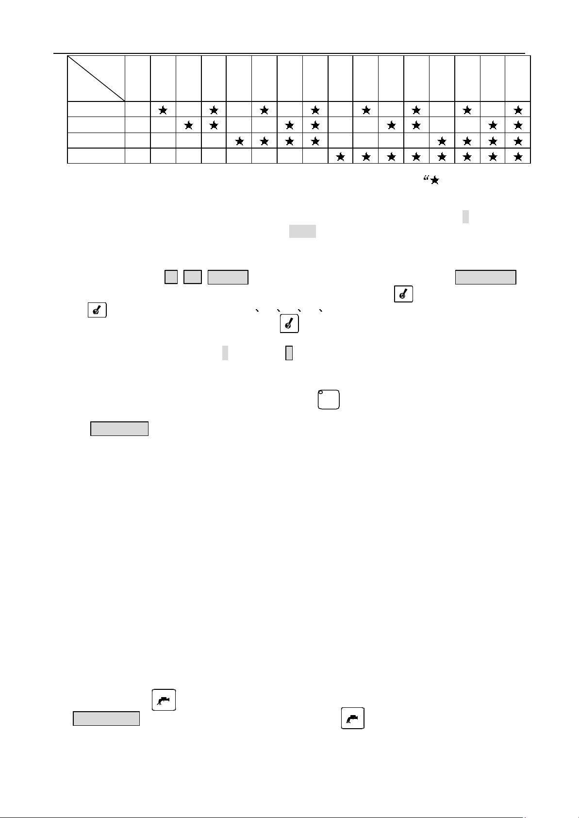
Operation GSK928TC Turning CNC System
code
output
bit
S1
S2
S3
S4
The output signal is valid to correspond to the bit with the symbol ”.
l Input the S code with keyboard to control the spindle rev. Push the button S, input the
required rev code, and push the button
with the defined code.
For example: Select the No.8 step spindle rev.
Orderly input S 8
In addition, switch the spindle rev by pushing the button too. By pushing this
button , the spindle rev changes in S1 S2 S3 S4 (P11,SCOD=0) or S0~S15(P11,SCOD=1). The
spindle rev switch from S2 to S1 by pushing the button trice when the spindle rev only has two steps.
l If the frequency conversion motor drives, input the the rev to control the spindle rev
directly. Push the button S to display S, then input the rev, and push the button Enter
to output the 0 ̄10V simulate voltage to the frequency invertor.
l Check the encoder lines. In Manual Jog mode, the pulse numbers per rotate can be checked
directly. Start the spindle, push the button , and then display the pulse number
per rotate. If the encoder isn’t assemblied exactly or the spindle isn’t started,
编码器信号错
l To increase the torque at the low frequency, some machine adopts teo steps gearshift.
This sytem offers a input signal SHL and the parameter P09, P10. The input signal SHL
is used to check the gearshift step. The parameter P09 is used to define the biggest rev
in the low gearshift step. The parameter P10 is used to define the biggest rev in the
high gearshift step. After input the rev directly, the rev will be translated into the
simulate voltage to control the frequency invertor.
l If the CHCD bit of the parameter P11 is 0, display the seting spindle rev. If the CHCD
bit of the parameter P11 is 1, display the actual spindle rev.
Note 1: The spindle rev control mode can be set by the MDSP bit of the parameter P12. MDSP=0, multilevel
Note 2: If the MDSP bit of the parameter P12 is 1, the SCOD bit of the parameter is invalid, the spindle
S00 S01 S02 S03 S04 S05 S06 S07 S08 S09 S10 S11 S12 S13 S14 S15
Enter
, then the rev control signal is exported
E nter
to output the S8 rev signal and display 编程转速 S08.
空运行
Dry
is displayed,push any button to return to the Manual Jog mode.
control; MDSP=1, 0 ̄10V simulate voltage control.
control is only frequency conversion control, and the outputs S1,S2,S3,S4 ,S0 ̄S15 and the s pindle
shift button are ineffective.
4.4.13 Manual coolant control
In manual Jog mode, start/stop the coolant
Push the button to start/stop the coolant. When the coolant is working, display
COOLANT ON
, at the same tome, the LED on the button is lightened.
20 GSK CNC Equipment Company
Page 21

Operation GSK928TC Turning CNC System
4.4.14 Manual Tool-exchange Control
Usually, this system can control the 4 position electric toolpost. By coding the tool number
T1 T4, it can control the 8 postion toolpost.
Three kinds of toolexchange methods:
Method 1. If set the MODT of the parameter P12 as 0, Push the button once, the toolpost
switches to the next postion, and display the next tool number.
Method 2. If set the MODT of the parameter P12 as 1, Push the buttons ,
switches to the next postion, and display the next tool number. After push the
button , push any other button except the button
Method 3. Input T * 0 directly by keyboard (* is the tool number to be employed), and push
the button
Note 1: In method 1 and 2, the tools can be exchanged, but it can
3, input the compensation number following the tool number *, the tool compensation can be executed.
For example:
Input T22, switch the No.2 tool and apply the No.2 tool compensation
Input T31, switch the No.3 tool and apply the No.1 tool compensation
Input T40, switch the No.4 tool and cancel the tool compe nsation
Input T00, escape the toolexchange and cancel the tool compensation
Note 2: If the electric toolpost is failure, display 刀位号报警 .
Note 3: This system adopts the absolute tool exchange, so every tool number is immovable on the toolpost.
When install the tool, the actual tool position must be accordant with the displayed tool number.
Note 4: When the TCON of the parameter P11 is 1, the lineup tool is choosed, there is not the signal output
when the tool exchanges.
Note 5: In method 3, the tool compensation can be realized by moving the slider of the machine or amendingthe
coordinate. It is defined with the PTSR of the paramete r P11.
PTSR=0 Move the slider to realize the tool compensation.
PTSR=1 Amend the coordinate to realize the tool compensation.
Enter
to switch to the
Enter
,the toolpost
Enter
, the tool will not exchange.
*
tool.
’
t realize the tool compensation. In Method
4.4.15 Manual Tool Regulate
Usually, many different tools are adopted in cutting one workpiece. The tools’ point can not
coincide due to install warp and different abrasion. To avoid the tool compensation at programming,
this system set the tool regulation that the tool offset can be created by this system automatically.
When user edits the user program according to the workpiece drawing and the cutting art, the tool
offset isn’t considered. In user program, transfer the corresponding tool compensation with
toolexchange dictate.
Here are the two methods in this system:
Trial cutting tool regulation:
(The workpiece coordinate must be defined first. The regulattion method is same as to define
the workpiece coordinate)
1. Install the trial workpiece reliably on the machine, and select any one of the tools
(usually the earlier using tool is selected)
2. Select the seemly spindle speed, then start spindle, move the tool in manual feed, cut
a little shoulder on the workpiece.
GSK CNC Equipment Company 21
Page 22

Operation GSK928TC Turning CNC System
3. Under the tool hasn’t any move on the X axis direction, the tool moves to the safe position
along the Z axis direction. Stop the spindle.
4. Measure the diameter of the shoulder, push the button I , the
input the metrical diameter then push the button
is the tool number), and push the button
Enter
Enter
, the system displays
, the tool offset in X axis is figured out
automatically, the system deposits the offset in the corresponding offset parameter
storage.
In the OFFSET mode, it can be amended or viewed. When display
of 1 ̄8,and push the button
Enter
,then the tool offset in X axis is figured out
automatically, the system deposits the offset in the corresponding offset parameter
storage. Otherwise push the button ESC to cancel the figuring and depositing the offset
in the X axis.
5. Start the spindle again, move the tool in manual feed, cut an end on the workpiece.
6. Under the t ool hasn’t any move on the Z axis direction, the tool moves to the safe position
along the X axis direction. Stop the spindle.
Select a datum mark (a fixure on the machine, such as chuck end, frock datum plane), measure
the distance from the datum mark to the machined end in the Z axis. Push the button K,
OFFSET X
T * X
is displayed,
T * X
(*
,input the a figure
the
OFFSET Z
display
is displayed,then input the metrical diameter and push the button
T * Z ( *
is the tool number), and push the button
Enter
, the tool offset in Z
Enter
,
axis is figured out automatically, the system deposits the offset in the corresponding
offset parameter storage.
In the OFFSET mode, it can be amended or viewed. When display
of 1 8,and push the button
Enter
,then the tool offset in Z axis is figured out
T * Z
,input the a figure
automatically, the system deposits the offset in the corresponding offset parameter
storage. Otherwise push the button
ESC
to cancel the figuring and depositing the offset
in the Z axis.
7. Change the next tool, Repeat the above approaches to seting this tool.
8. If the workpiece coordinate hasn’t any change, All tools can be regulated such this.
Pointing tool regulation
1. Install the trial workpiece reliably on the machine, and select any one of the tools
(usually the earlier using tool is selected) as a reference tool.
2. Select the seemly spindle speed and start the spindle.
3. Select the seemly manual feed speed. In Manual Jog mode, move the tool to close to the selected point
on the workpiece. After confirm the tool point coincides with the selected point on the workpiece, stop
moving the tool.
4. Push the button Enter, the tool number and tool offset are displayed with highlight, push the
button twice continuously. The display of the tool number and tool offset is in normal again,
now the tool coordinate is deposited, and this tool coordinate goes into the benchmark to regulate the
other tools. (Except the reference tool, the other tool can’t be operated with this approach).
5. Push the button Enter, and the button to confirm, (if regulate the tool again for the damage of the
primary tool, please push the button ), the display of the tool number and the tool offset is in
输入
改写
normal, the tool number and the tool offset are figured out and deposited the current tool parameter
storage. In the OFFSET mode, the tool offset can be amended or viewed.
22 GSK CNC Equipment Company
Page 23

Operation GSK928TC Turning CNC System
6. In Manual Jog mode, Move out the toolpost to the position where the tool can be exchanged safely.
Exchange the regulating tool to the working position.
7. Repeat the above approach 2, 3, 5 up to finished the all tool regulations.
Note 1: With tool regulator, the regulate point should be set at the cross point of the tool regulator
when the spindle stops.
Note 2: In the OFFSET mode, the created tool offset can be amended and viewed. C onsult the description
on the OFFSET mode.
Note 3: If the tool is damaged or replaced, select any other tool as the reference tool. Fisrt, regulate
the reference tool to the selected pointg on the workpiece and confirm the oofset as reference
tool such as above approach 4, but refuse above approach 5. Escape to the safe positon to exchange
the new tool, and then repeat above approaches 2, 3, 5 to regulate the non-reference tools. (The
offset of the primary tool isnot always zero)
Note 4: If there are the lineup tools in use, the metrical offset is negative in trial cutting tool regulation
when the regulating tool is on the other side of the workpiece. Rewrite the sign of the offset
by pushing the button +/ - in the pointing tool regulation.
4.4.16 Manually return to the program reference point.
After defined the program reference point (program origin), push this button to return to
this point at any moment.
X
X axis returnning to program reference point Button : It is valid only on the JOG/AUTO mode.
Push this button to return from the current positon to the program reference point in x axis with the current quick
move speed.
Z
Z axis returnning to program reference point Button: It is valid only on the JOG/AUTO mode.
Push this button to return from the current positon to the program reference point in z axis with the current quick
move speed.
Note: After return to the program reference point in X axis and Z axis, all tool offset and system offset are cancelled,
and display T * 0 ( the * is the current tool number).
4.4.17 Manually return to the machine reference point (mechanic origin)
Fix a machine reference point on the machine. After return to the machine reference point,
go back to the start position (the start position must be set first) to delete cumulation error
or to avoid the accident.
Note: to cancel the function to return to the machine reference point, set the MZRO bit
of the parameter P12 on 0.
X axis returnning to machine reference point Button: It is valid only on the JOG mode. By
X
pushing this button, move the tool to the machine reference point in X axis with the current quick move speed.
Z
Z axis returnning to machine reference point Button: It is valid only on the JOG mode. By
pushing this button, move the tool to the machine reference point in X axis with the current quick move speed.
If the MZRM bit of the parameter P12 is 0, the reset process is as follows:
1 The slider moves along the positive direction of the appointed axis. After the block on the
GSK CNC Equipment Company 23
Page 24

Operation GSK928TC Turning CNC System
X 0090. 000
Z 0125. 000
自动
slider pushes down the reset deceleration switch, the slider begin to decelerate to the lowest
speed (it is defined by the parameters P17 or P18), and keep moving with this speed until
the block disengages from the reset deceleration switch.
2 When this system receive the encode signal (or the zero signal of the proximity switch),
the slider arrive at the coordinate origin, the slider stops to finish the reset.
If the MZRM bit of the parameter P12 is 1, the reset process is as follows:
1 The slider moves along the positive direction of the appointed axis. After the block on the
slider pushes down the reset deceleration switch, the slider begin to decelerate to the lowest
speed (it is defined by the parameters P17 or P18), and keep moving with this speed to reset
the coordinate.
2 When the block disengages from the reset deceleration switch, the reset finishes.
Note 1: Returnning to the machine reference point is positive, so confirm that the toolpost i s in the negative
direction of the machine reference point before returning to the machine reference point.
Note 2: To avoid the accident, the MZRO bit of the parameter P12 must be defined in 0, if there has n ot
the reset deceleration switch on the machine .
4.5 AUTO mode
In AUTO mode, this system runs according to the user program step by step.
Push the button to enter AUTO mode. There have try run, machining run, single segment
run and continuous machining run in AUTO mode.
AUTO
AUTOCONTINUE %00
*N0000 G50 X100 Z100
N0010 M3 S2
FEEDRATE 100% SPINDLE STOP
FASTRATE 100% SPDL REV 0000
COOLANT OFF TOOL 1 OFFSET 0
EDIT MANU AUTO PARA OFFT DIAG
PICTURE 15 AUTO mode
4.5.1 Fuction buttons in AUTO mode
单段
Single
Change the run mode between AUTO SINGLE and AUTO CONTINUE by pushing the button , the
corresponding run mode is displayed as
mode. When the program is running in Auto Continue mode, it can pause after the current segment
24 GSK CNC Equipment Company
Switch between AUTO SINGLE mode and AUTO CONTINUE mode.
AUTO SINGLE
in singlo mode or
AUTO CONTINUE
单段
Single
in continue
Page 25
Operation GSK928TC Turning CNC System
Input
by pushing this button. Run the next segments by pushing the RUN button .
空运行
Dry
Change the run mode between dry running mode and machining mode by pushing this button .
In dry running mode, the LED on the button is light, the sliders of the machine are actionless
and the other assistant functions are invalid. In machining mode, the LED on the button is
lightless.
Push this button to select the segment to be run, then push then button to
start from this segment.
In AUTO SINGLE mode, push this button to run one segment. In loop dictate, an action
will be carried out by pushing this button.
In AUTO continue mode, push this button to run the all program once from cover to cover.
When the program is running, push this button to speed-down and stop, then it displays
Switch between dry running mode and machining mode
空运行
Dry
输入
Select the segment number
Input
输入
Input
Run button
Feed hold button
空运行
Dry
PAUSE!
with highlight. Push the run button to next program, otherwise, push the button
ESC
to
escape from the current program running.
4.5.2 Run the program automatically
Enter the Auto mode after all are ready, run the selected program orderly to machine the
workpiece automatically.
4.5.2.1 Run from the first row of the program
After enter the AUTO mode, the two segment to be run are displayed, and the sign * is displayed
in front of the current segment. Push the Run button to start running automatically.The
running segment is displayed on top, the second row is the segment to be run.
4.5.2.2 Run from the appointed row in the program
In some special conditions, it is necessary to run from the appointed segment in the program.
This system allows to start the current program from any segment in this program and to park the
toolpost on the corresponding position.
1. Select the appointed row in the program to be run.
a) Push the button to display the first row in the current program.
输入
b) Push the buttons to page up/down the displayed segments. Push ESC to return
to the former displayed segment.
2. When the appointed segment is displayed on top, push the button
prompts
RUN?
to wait for the next operation.
Enter
, then the system
GSK CNC Equipment Company 25
Page 26
Operation GSK928TC Turning CNC System
3. When the system prompts RUN? , push the Run button to move to the corresponding
coordinates automatically as same as G00 mode. Otherwise, push the button ESC to return
to the former displayed segment.
4. Push the button again to run from the appointed segment automatically.
Note 1: The appoint segment can’t be in any fixed loop or compound loop, otherwise the result must be out of
expectation.
4.5.2.3 Single segment run and continue run
Validate the new program with Single mode. Run one segment by pushing the Run button
once.After confirm the action of the machine is exact, push the Run button to run the
next segment, repeat above operation up to the end of the program. Otherwise, if there has any
segment unsuitable for the expectant action, stop running to return to the program reference point.
Correct the program thouroughly, then can run the program in Auto continue mode.
Switch between SINGLE mode and CONTINUE mode by pushing the button .
单段
Single
1. Push the button when there has not the program that it is running, switch between
SINGLE mode and CONTINUE mode, and display the corresponding mode. Display
segment running mode, display
2. When there has a program that it is running, push this button to pause after finish
the current segment, and display
单段
Single
AUTOCONTINUE
SINGLE STOP
in continue running mode.
with highlight as PICTURE 16. Push the Run button
单段
Single
AUTO SINGLE
in single
to continue running the next segments in AUTOCONTINUE mode. Only after finish the current
program, can switch to the SINGLE mode by pushing the button . Single Stop can be repeated
单段
Single
in running one program continuously.
3. The button is invalid in running the program with SINGLE mode.
单段
Single
Note: The initial state is AUTOCONTINUE mode.
4.5.2.4 Dry run and machining
Validate the new program with dry run mode before machining with the program. This system
can display the coordinates in dry run mode, so can check if the coordinates agree with the actual
demand, if the relations between segments are exactly to avoild the accident of error data input.
Switch Dry run mode and machining mode bu pushing the button . The led on the button is
空运行
Dry
空运行
Dry
lighting in Dry run mode.
N ote 1 . In Dry run mode, the coordinates don
Note 2. The initial state is Machining mode when enter AUTO mode.
’
t move, the assistant functions are invalid.
26 GSK CNC Equipment Company
Page 27

Operation GSK928TC Turning CNC System
X 0090. 000
Z 0125. 000
X 0090. 000
Z 0125. 000
PICTURE 17 DISPLAY IN PROGRAM RUNNING
AUTOCONTINUE %00 SINGLE STOP
*N0000 G50 X100 Z100
N0010 M3 S2
FEEDRATE 100% SPINDLE STOP
FASTRATE 100% SPDL REV 0000
COOLANT OFF TOOL 1 OFFSET 0
EDIT MANU AUTO PARA OFFT DIAG
PICTURE 16 SINGLE STOP
4.5.3 Display in program running
In program running, this system can display the running states, coordinates, workpiece planar
skeleton map, and trail of tool point and so on. It is very convenient to monitor and control
the system and the machine.
Display contents:
1. The dynamical coordinates, the dynamical planer outline or the trail of tool point
2. The contents of the current running segment
3. The states of spindle, coolant, rev, tool and other assistant functions
4. Feed and quickmove speed multiple
4.5.3.1 Coordinates display in program running
The initial display mode is the coordinates display when enter the AUTO mode as PICTURE17.
Push the button
change from the coordinates display into trace display, only can display the trail of the tool
point after switch, the trail of the tool point can’t be displayed before switch.
T
N0010 M3 S2
to switch between the coordinates display and the trail display. When
AUTOCONTINUE %00
*N0000 G50 X100 Z100
FEEDRATE 100% SPINDLE STOP
FASTRATE 100% SPDL REV 0000
COOLANT OFF TOOL 1 OFFSET 0
EDIT MANU AUTO PARA OFFT DIAG
4.5.3.2 Figure display in program running
When there has not the program that is running in AUTO mode, push the button
GSK CNC Equipment Company 27
T
to display the
Page 28
Operation GSK928TC Turning CNC System
PARA OFFT DIAG
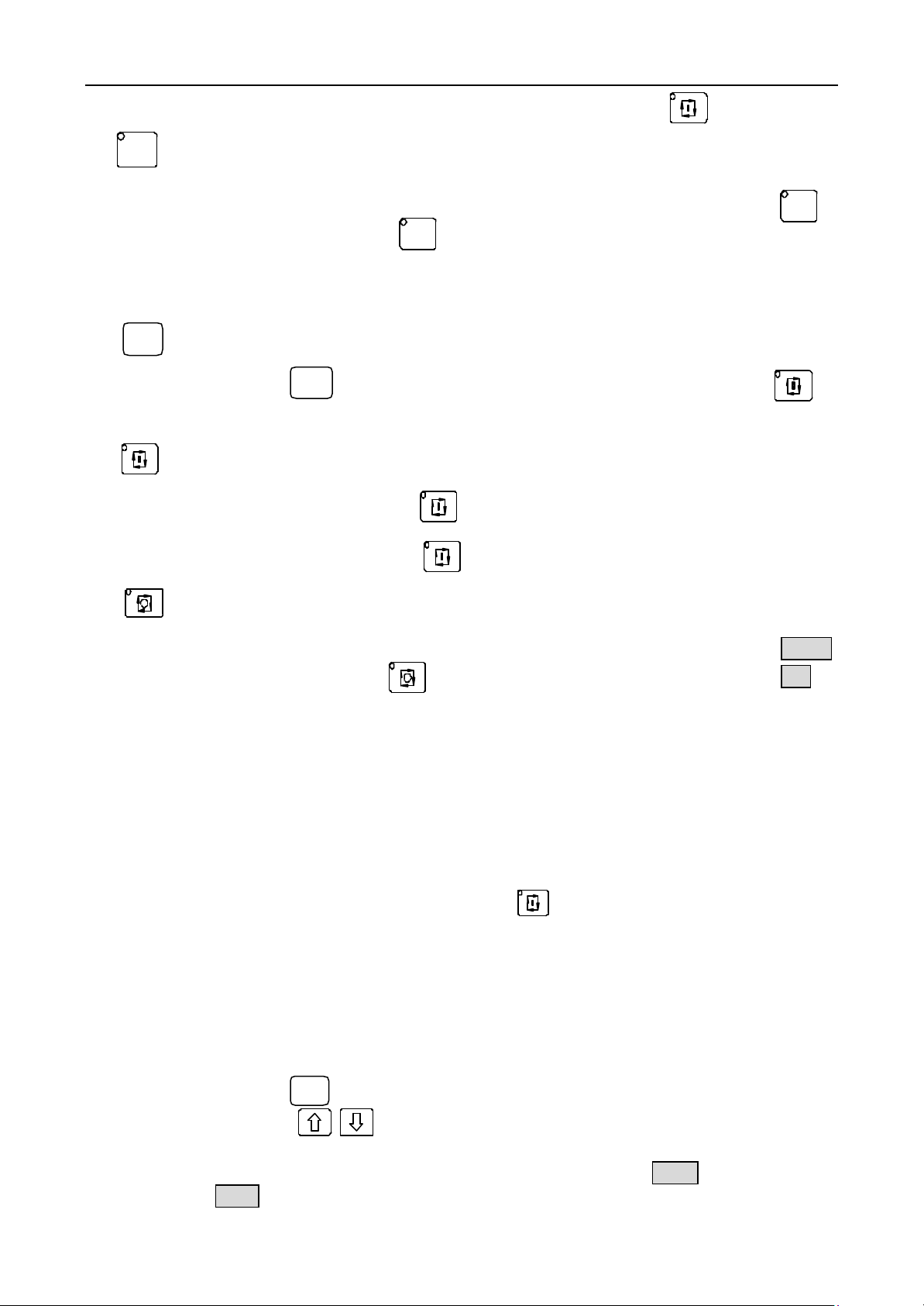
workblank outline with actual planar dimensions and the simulated tool shape as PICTURE 18.
Switch between the actual planar outline display and the trail display of the tool point
by pushing the button
PICTURE 18 ACTUAL PLANAR OUTLINE DISPLAY IN AUTO MODE
N0000 G50 X100 Z100
EDIT MANU AUTO PARA OFFT DIAG
Z
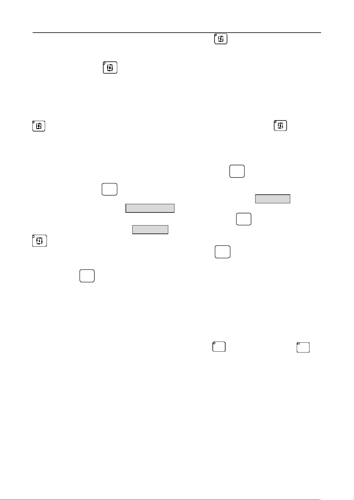
when there has not program that is running in AUTO mode as PICTURE19.
N0000 G50 X100 Z100
PICTURE 19 THE TRAIL DISPLAY OF THE TOOL POINT
AUTO CONTINUE %00
Z
X
FEEDRATE 100% SPINDLE STOP
FASTRATE 100% SPDL REV 0000
COOLANT OFF TOOL 1 OFFSET 0
AUTO CONTINUE %00
Z
X
FEEDRATE 100% SPINDLE STOP
FASTRATE 100% SPDL REV 0000
COOLANT OFF TOOL 1 OFFSET 0
EDIT MANU AUTO
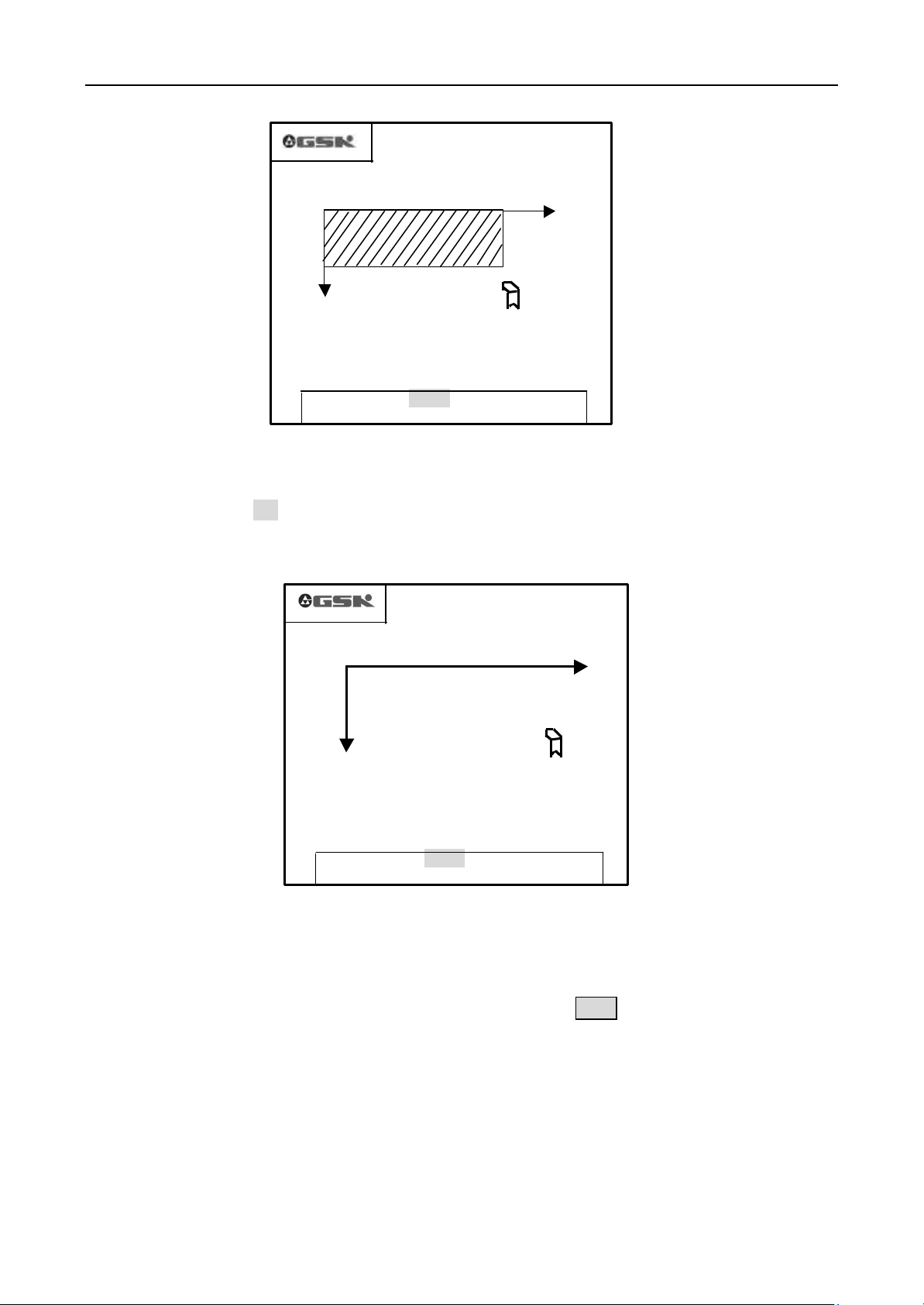
4.5.3.3 Define the data of the figure display
The screen area of this system is limited, so the figure display can be defined in this system with workblank
length and diameter, tool initial offset and display scale. Push the button Enter to set the workblank length and
diameter, tool initial offset and display scale in the actual planar outline display or the trail display of
the tool point as PICTURE 20.
28 GSK CNC Equipment Company
Page 29
Operation GSK928TC Turning CNC System
Z
PICTURE 20 DEFINE THE DATA OF THE FIGURE
Length: Total length of the workblank, unit : mm
Diameter: Max. Diameter of the workblank, unit : mm
Offset: The distance in Z axis from the program reference point to the machining start on the workblank (the
program reference point in X axis is the center of the workblank), unit: mm
N0000 G50 X100 Z100
长度
FEEDRATE 100% SPINDLE STOP
FASTRATE 100% SPDL REV 0000
COOLANT OFF TOOL 1 OFFSET 0
EDIT MANU AUTO PARA OFFT DIAG
AUTO CONTINUE %00
Z
X
100
直径
80
偏移
0
比例
2:1
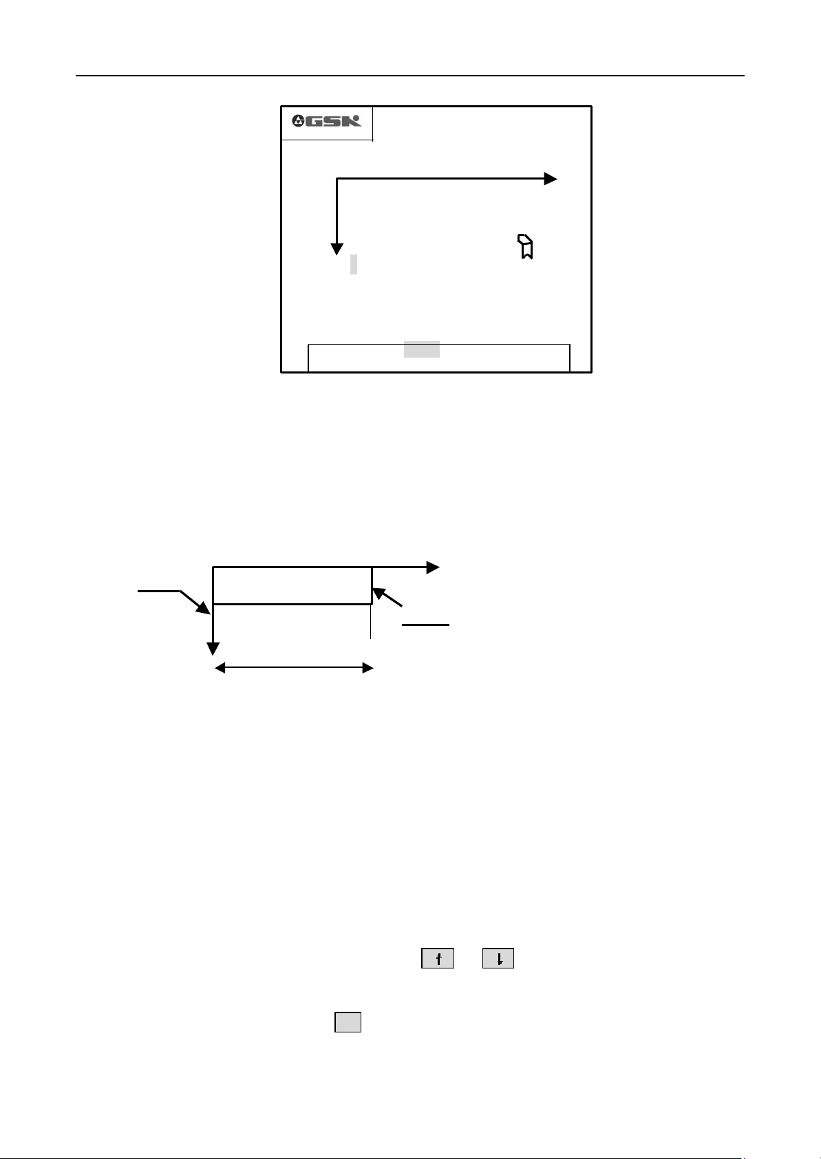
e.g. Workblank length: 100mm
Endface1
Endface 2
If the program reference point is at the endface 1, the offset is 0.
If the program reference point is at the endface 2, the offset is 100.
Display scale: It ensures the display size but it doesn’t change the actual machining dimensions. If the
dimension of the workblank isnot suitable for the screen size, the display scale can be adjusted to display the
workblank properly.
X
4.5.3.4 Input the data of figure display
When there has no program that is running or that pauses in AUTO mode, push the button Enter
to display the current data as PICTURE 18, and the cursor points to the first figure of the
length.Input the data, push the button Enter to confirm and input the next group of data. Recycle
in the 4 group of data by pushing the button Enter.
Adjust the display scale by pushing the button
scale.The display scale has 7 steps as 4:1 3:1 2:1 1:1 1:2 1:3 1:4. It can be adjusted to
realize the best display effect.
After adjustment, push the button
the figure dimensions are amended according to the new display scale and the other new data
automatically.
ESC
to return to the Auto mode. If it is the figure display,
or
when the cursor is at the display
GSK CNC Equipment Company 29
Page 30
Operation GSK928TC Turning CNC System
When the display data overrun the screen. The system prompts XZ overlimit, the display data
must be modified again.
Note 1: The start position of the tool must be out of the workblank outline, otherwise, the machining processs
can’t be displayed exactly.
Note 2: Switch from coordinates display to figure display in machining, only the part of next machining
trail can be displayed, but the part of former machining trail can’t be displayed. Especially switch
to the actual planar outlind display, the workpiece outline can
new loop.
’
t be displayed normally before a
4.5.4 Operation of the assistant functions
In Auto mode, all the machine assistant functions such as spindle, coolant, speed and other controls can be
operated by pushing corresponding buttons manually without the program in running. The coolant can be
controlled in running.
Spindle positive rotation button The spindle rotates counter-clockwise (watch from the motor
shaft) and the Led on this button is lighted by pushing this button.
Spindle stop button The spindle stops running and the Led on the button or is
extinguished when push this button.
Spindle negative rotation button The spindle rotates clockwise (watch from the motor shaft)
and the Led on this button is lighted by pushing this button.
Coolant button Switch the coolant on/off. When start the coolant, display COOLANT ON on
the secreen and the Led on this button is lighted. When stop the coolant, display COOLANT OFF on the screen
and the Led on this button is extinguished.
Spindle shift button Select the spindle speed when the main spindle motor has more then one
step speed (not more then 16 steps) and the machine has the control loop.
Note 1: The toolchange fuction can
’
t be operated in Auto mode.
4.5.5 Adjustment of the speed mutiple
In Auto mode, the speeds can be adjusted by the speed multiple, but the program or the
parameter hasn’t to be amended.
Feed speed multiple
It is displayed as
Actual feed speed
FEEDRATE
: adjust the feed speed defined by F dictate.
=
F * feed speed multiple
.It has 16 steps from 0% ̄150% (distance 10%). All the feed speed
dictates are restricted by the f eed speed multiple. When the multiple is 0, the running stops.
By pushing the button , increase the feed speed multiple up to 150%
By pushing the button , reduce the feed speed multiple up to 0%.
Fast move speed multiple
X axie actual fast move speed
Z axie actual fast move speed
: adjust the fast move speed defined in
=
Parameter P05 * fast move speed multiple
=
Parameter P06 * fast move speed multiple
G00
and other dictates.
30 GSK CNC Equipment Company
Page 31

Operation GSK928TC Turning CNC System
It is displayed as fastrate. It has 4 steps 25%, 50%, 75%, 100%. All the fast move dictates
and the actions are restricted by the fast move speed multiple.
By pushing the button , increase the fast move speed multiple up to 100%
By pushing the button , reduce the fast move speed multiple up to 25%.
Note 1: whether there has the program in running, the feed speed multiple and the fase move speed multiple
can be adjusted by push the corresponding buttons. And the speed will be changed in running with the
corresponding multiple.
4.5.6 Some operations in running
Feed hold
Push the button , the tool speeds down and stop, display
PAUSE!
on the screen.
For run the next segments, push the button . For escape from feedhold, stop running the
next segments, and switch to AUTO SINGLE mode, push the button .
退出
Esc
Single stop
Push the button , the running pauses after finish the current segment running, and
display
SINGLE STOP
from SINGLE stop to AUTO mode, and stop the running, push the button .
单段
Single
on the screen. For run the next segments, push the button .For escape
退出
Esc
Note 1: The single stop is valid in AUTOCONTINUE mode. It is invalid in AUTO SINGLE mode. In running
the fixed loop dictates, it is valid after finish once of this loop.
Coolant start/stop
Push the button , start or stop the coolant. When it switches on, the Led on
the button is lighted. When it switches off, the Led on the Button is extinguished.
Speed multiple adjustment
Both feed speed multiple and fast move speed multiple can be amended in running, and it is invalid
immediately as soon as it is amended. The multiple adjustment is as chapter 4.5.5 Adjustment of the
speed multiple .
If the feed speed multiple is 0 before running, the system prompts FEEDRATE 0%. When adjust the
feed speed multiple to 0% in running, the running stops without prompt. If adjust the feed speed multiple
isnot 0, the running carrys on.
4.5.7 Return to the program reference point in AUTO mode
For simplify the operation, the program can be started anywhere the tool stays after the workpiece coordinates
and the program reference point are defined. But the first dictate must be G00, and the X and Z axes cooedinates
must be defined with absolute coordinates. All resets by the reset button, and G26/G27/G29 dictates are returning
to the program reference point. After G26/G27/G29, the two axes absolute coordintes must be positioned with
G00 at the same time to ensure that the current workpiece keeps on being machined exactly. After reset by the
reset button, the system returns to the first segment of the program automatically. If push the run button ,
then the system runs from the first segment.
GSK CNC Equipment Company 31
Page 32

Operation GSK928TC Turning CNC System
on the
different machine. Please refer to the operation manual of the
4.5.8 Feedhold knob in running automatically
There has an interface to the external feed/spindl hold knob, It can control the spindle rotation and slider
move.this knob is very convenient to debug a new program by controlling the spindle and the slider. This knob has
three positions corresponding to three kinds controls as follows:
Position 1: Permit the spindle rotation and the slider move.
Position 2: Permit the spindle rotation, prohibit the slider move.
Position 3: Prohibit the spindle rotation and the slider move.
Note: The identifier of the feedhold knob may be different
machine.
Feedhold knob
4.5.8.1 Application of the feedhold knob
In front of running program:
The spindle can start or stop with the spindle control buttons when the knob at position 1 or position2. but the
spindle can’t start or stop with the spindle control buttons when the knob at position 3.
In Auto single mode
When the knob at position 1, all dictates run as normal. When the knob at position 2, spindle dictates run as
normal but the X,Z axis move dictates don’t run. When the knob at position 3, any dictate can’t run.
In Auto continue mode
After start the program, the knob can be adjustable at any moment to control the spindle and the move.
When the knob at position 1, the program runs as normal.
When the knob from position 1 to position 2, the slider move pauses, but the spindle keeps the previous
condition.
When the knob from position 2 to position 3, the spindle stops.
When the knob from position 3 to positon 2, the spindle resumes the previous condition.
When the knob from position 2 to position 1, the slider mover resumes the previous condition.
When the feed holds and spindle stops, push the button ESC or reset button, this system escapes from auto
running. The non-execution dictates and the spindle can’t be held. If keep on machining, only start the program
again.
4.6 Parameter setup
There have 23 group parameters numbered from P01 to P23 in this system. Each parameter is defined to
confirm a certain function of this system and the machine, so the parameters must be defined again when
installation and adjustment of the machine and the CNC system.
Push the button PAR to enter the parameter setuo mode. The first screen is from P01 to P09 as follows:
32 GSK CNC Equipment Company
Page 33

Operation GSK928TC Turning CNC System
P01 8000.000
P02 -8000.000
P03 8000.000
P04 -8000.000
P05 06000
P06 06000
P07 00.000
P08 00.000
P09 0000
Z AXIS OBVERSE LIMIT
EDIT MANU AUTO PARA OFFT DIAG
PARAMETER
PICTURE 21 PARAMETER SETUP
Push the button or to page up/down the screen to display the other parameters (9
parameters in one screen). And push the button
the next one and its definition.
4.6.1 Parameter instruction
When the parameter number is choiced, the parameter is displayed as highlight, and its definition is displayed
under it.
4.6.1.1 Parameter P01, P02--Z axis positive,negative overtravel limit
Parameters P01, P02 define the Max. travels in Z axie positive, negative directions separately. If the Z axis
coordinate isnot less then that defined by the parameter P01 (positive limit), the slider can’t move along positive
direction, but it can move along negative direction. If the Z axis coordinate isnot bigger then that defined by the
parameter P02 (negative limit), the slider can’t move along the negative direction, but it can move along the
positive direction. Unit: mm
4.6.1.2 Parameter P03, P04—X axis positive, negative overtravel limit
Parameters P03, P04 define the Max. travels in X axis positive, negative directions separately. If the X axis
coordinate isnot less then that defined by the parameter P03 (positive limit), the slider can’t move along positive
direction, but it can move along negative direction. If the X axis coordinate isnot bigger then that defined by the
parameter P04 (negative limit), the slider can’t move along the negative direction, but it can move along the
positive direction. Unit: mm
or
to display the front parameter or
Note 1: Though the coordinates scale is 16000 ( 8000) but the absolute move can’t be bigger then 8000.
4.6.1.3 Parameter P05—Z axis fast move speed
Parameter P05 defines the Z axis fast move speed in manual move and in G00. The actual fast move speed in
Z axis is restricted by the fast move speed multiple, too. Z axis actual fast move speed=P05* fast move speed
multiple. Unit: mm/min
GSK CNC Equipment Company 33
Page 34

Operation GSK928TC Turning CNC System
4.6.1.4 Parameter P06—X axis fast move speed
Parameter P06 defines the X axis fast move speed in manual move and in G00. The actual fast move speed in
X axis is restricted by the fast move speed multiple, too. X axis actual fast move speed=P06* fast move speed
multiple. Unit: mm/min
4.6.1.5 Parameters P07 P08—Compensations of the reverse clearances in Z, X axie
Parameters P07, P08 define the compensations the mechanical reverse clearance in Z, X axis separately. Unit:
mm
There have clearances in the thread, the reducer, and the other transmissions of the machine, so the errors
must happen in the reciprocating movement. After set the parameters P07, P08, this system can compensate the
errors when the movement changes the direction.
Measurement of the mechanical reverse clearances: (Example for Z axis):
1. Select the JOG mode and the proper feed speed.
2. Assembly the dial indicator on the proper position on the machine, Move the tool to touch the probe of the
dial indicator and adjust the finger of the dial indicator at zero.
3. Select the JOG Single feed mode with the step 1.0mm.
4. Push the button or to move the toolpost to the dial indicator, let the finger of the dial indicator
run one circuit and point to the zero again.
5. Push the button or to move the toolpost away from the dial indicator for the same distance,
let the finger of the dial indicator run back, but it can’t return to the 0 for the clearance. Then the distance from
reading to the zero is the Z axis reverse clearance.
Note 1: Repeat above approaches some times to obtain the exact value.
Note 2: Measurement of the X axis reverse clearance is same as above approaches. But the observed result must time 2
to change into the diameter value.
Note 3: Compensate the reverse clearances in X, Z axis with the start speed (defined by P17, P18) .
4.6.1.6 Parameter P09 – Low spindle speed
Parameter P09 deifnes the spindle convertor control with low gear speed, and then the syetem output 10V
DC signal corresponding to the Max. speed. The parameter P09 is invalid when control the spindle speed with S
progression. Unit: rev/min.
4.6.1.7 Parameter P10 High spindle speed
Parameter P10 deifnes the spindle convertor control with high gear speed, and then the syetem output 10V
DC signal corresponding to the Max. speed. The parameter P10 is invalid when control the spindle speed with S
progression. Unit: rev/min.
Note 1: When there haven’t the high/low parts of the spindle speed control, define the max speed with parameter
P10. then the parameter P09 is invalid.
4.6.1.8 Parameters P11, P12—bit parameter 1, bit parameter 2
For the different requirements of the different machine, some control functions of this system can realize the
different functions by defining the corresponding bit in the parameters P11 , P12 with 0 or 1.
The 8 bits named as D7~D0 from left to right. Each bit can be set as 0or 1.
34 GSK CNC Equipment Company
Page 35

Operation GSK928TC Turning CNC System
Bits of parameter P11 instructions
D7
WHLA PTRS TCON SCOD CHCD LINE DIRZ DIRX
DIRX
X axis rotation direction
DIRZ
Z axis rotation direction
CHCD CHCD=0
CHCD=1
LINE LINE=0
LINE=1
SCOD SCOD=0
SCOD=1
TCON TCON=0
TCON=1
PTSR PTSR=0
PTSR=1
WHLA WHLA=0
WHLA=1
D6
D5
D4
D3
D2
D1
D0
Don’t check the encoder lines in diagnose mode or JOG mode, but the spindle
setting rev is displayed in JOG mode.
Check the encoder lines in diagnose mode or JOG mode, but the actual spindle rev is
displayed.
The spindle encoder pulse number per rotation:1200pulse/rev
The spindle encoder pulse number per rotation:1024pulse/rev
S1 S4, 4 steps spindle rev direct output
S0 S15, 16 step spindle rev coding output
Electric turret toolpost
lineup tool
Move the slider to run the tool compensation
Amend the coordinates to run the tool compensation
The multiple 0.1mm is valid with handwheel
The multiple 0.1mm is invalid with handwheel
When the bit SCOD of parameter P11 is 1, the coding list of the S codes:
code
output
S1
S00 S01 S02 S03 S04 S05 S06 S07 S08 S09 S10 S11 S12 S13 S14 S15
S2
S3
S4
The outputs with are valid in above table.
Note 1: By seting the DIRX and DIRZ as 0 or 1, the X, Z axis motors
without any external adjustment. So let the slider move direction consists with the defined
direction. Power on again or push the button to make the adjustment valid after adjustment.
Note 2: D7,D6 are standby .
’
rotation direction can be changed
Bits of parameter P12 instructions P12
D07
D06
D05
D04 D03 D02
D01
D0
MZRO DLMZ DLMX MZRM MSP MODM MODT MDSP
MDSP 0 Spindle rev progression control
1 Spindle rev analog control (0~10VDC) (frequency conversion spindle)
MODT 0 Push the tool change button to change the tool directly
1 Push the button Enter to change the tool after push the tool change button .
GSK CNC Equipment Company 35
Page 36

Operation GSK928TC Turning CNC System
MODM 0 Start/stop of the spindle and the coolant are controlled with power level (only M03/04/05,
M08/09 are controlled)
1 Start/stop of the spindle and the coolant are controlled with pulse (the other M signals are
power level )
MSP 0 Stop the spindle without brake signal output
1 Stop the spindle with brake signal output (the brake time is defined by the parameter P16)
MZRM 0 Return to the mechanical point with checking one rotation signal
1 Return ot the mechanincal point without checking one rotation signal
DAMX 0 Display X AXIS DRIVER ALARM when the driver alarm input signal in X axis is high
level.
1 Display X AXIS DRIVER ALARM when the driver alarm input signal in X axis is low
level.
DAMZ 0 Display Z AXIS DRIVER ALARM when the driver alarm input signal in X axis is high
level.
1 Display Z AXIS DRIVER ALARM when the driver alarm input signal in X axis is low
level.
MZRO 0 The function to return to the mechanical point is invalid.
1 The function to return to the mechanical point is valid.
4.6.1.9 Parameter P13—the most tool positions
Parameter P13 sets the most tool positions on the machine. This system defaults 4 positions. When it can
expand 6~8 positions with coding the position signals.
4.6.1.10 Parameter P14—Toolpost reverse time
Parameter P14 sets the retentive signal time of reverse to lock the toolpost. Unit: 0.1 second
Note 1: The value of the parameter P14 must be adjusted to fit for the assemblied toolpost. If the value of the parameter
P14 is too big, the motor of the toolpost may be damaged. If the value of the parameter P14 is too small, the toolpost
can’t be locked.
4.6.1.11 Parameter P15— The pulse time of the M code
Parameter P15 sets the pulse time when the spindle and coolant control with pulse mode. U nit: 0.1second.
4.6.1.12 Parameter P16—The signal time of the spindle brake
Parameter P16 sets the signal time of the spindle brake. Unit: 0.1second.
4.6.1.13 Parameter P17—The lowest start speed in Z axis
Parameter P17 sets the lowest start speed in Z axis with G00 dictate or in JOG mode. Unit: mm/min
When the actual Z axie speed is lower then the value of the parameter P17, there has not the speed up/down
process in Z axis. The value of the parameter P17 must be adjusted to fit for the machine.
4.6.1.14 Parameter P18—The lowest start speed in X axis
Parameter P18 sets the lowest start speed in X axis with G00 dictate or in JOG mode. U nit: mm/min
When the actual X axie speed is lower then the value of the parameter P18, there has not the speed up/down
process in X axis. The value of the parameter P18 must be adjusted to fit for the machine.
4.6.1.15 Parameter P19—The speed up/down time in Z axis
Parameter P19 sets the speed up/down time in Z axis from the lowest start speed (P17) to the higest speed (P5)
linearly with G00 dictate or in Jog mode. Unit: millisecond.
The speed up/down time in Z axis increase with the value of the parameter P19. So the value of the parameter
36 GSK CNC Equipment Company
Page 37

Operation GSK928TC Turning CNC System
should be shorter as soon as possible based on satisfying the load characteristic.
4.6.1.16 Parameter P20—The speed up/down time in X axis
Parameter P20 sets the speed up/down time in X axis from the lowest start speed (P18) to the higest speed
(P6) linearly with G00 dictate or in Jog mode. Unit: millisecond.
The speed up/down time in X axis increase with the value of the parameter P20. So the value of the
parameter should be shorter as soon as possible based on satisfying the load characteristic.
4.6.1.17 Parameter P21—The feed start speed
Parameter P21 sets the start speed of the G01, G02, G03 and other feed dictates in Auto mode. Unit: mm/min.
There has not the speed up/down procees when the speed defined with F is lower then the value of the parameter
P21.
4.6.1.18 Parameter P22—the feed speed up/down time
Parameter P22 sets the time to increase/reduce the speed of G01, G02, G03 and other feed dictates in Auto
mode from the speed appointed by the parameter P21 to 6000mm/min. Unit: millisecond
By adjusting the parameters P5, P6, P17~P22, this system can fit for the different motors or the machines with different
loads to increase the machining efficiency.
4.6.1.19 Parameter P23 The space between two sequence numbers of the program
Parameter P23 sets the increment of the sequence number in Edit mode, the space between teo sequence
numbers.
Parameters list in this GSK928TC system:
Parameters
number
P01 Z axis positive limit mm 8000.000 0~8000.000
P02 Z axis negative limit mm -8000.000 -8000.000~0
P03 X axis positive limit mm 8000.000 0~8000.000
P04 X axis negative limit mm -8000.000 -8000.000~0
P05 Z axis max. speed mm 6000 0~15000
P06 X axis max. speed mm 6000 0~15000
P07 Z axis reverse clearance mm 00.000 0~65.535
P08 X axis reverse clearance mm 00.000 0~65.535
P09 Spindle low rev rpm 1500 0~6000
P10 Spindle hig rev rpm 3000 0~6000
P11 Bit parameter 1 00000000 0~11111111
P12 Bit parameter 2 00000000 0~11111111
P13 Tool positions 4 1~8
P14 Toolpost reverse time 0.1second 10 0.1~99.9
P15 M code time 0.1second 10 0.1~99.9
P16 Spindle brake time 0.1second 10 0.1~99.9
P17 Z axis lowest start speed mm/min 50 8~1000
P18 X axis lowest start speed mm/min 50 8~1000
P19 Z axis speedup time millisecond 600 8~9999
P20 X axisspeedup time millisecond 600 8~9999
Definition Unit Initial value Scale
GSK CNC Equipment Company 37
Page 38

Operation GSK928TC Turning CNC System
P21 Feed start speed mm/min 50 8~6000
P22 Feed speed up/down time millisecond 600 8~9999
P23 The space between two
sequence numbers
10 1~255
4.6.2 Parameters input
All the parameters of this system are initialled before it leaves factory. When it is assemblied on the machine,
it is necessary to adjust the parameters according to the actual conditions.
Approaches of parameter input:
1. Enter the Parameter mode.
2. Move the cursor to the parameter to be amended with highlight by pushing the button or
(display the corresponding definition of the parameter at the bottom of the sreen), then push the
button
输入
Input
to display a highlight square that can be amended.
3. Input the parameter value by keyboard. Push the button to delete the wrong input.
4. Push the button Enter to confirm.
e.g. Adjust the parameter P05 to 4500 as PICTURE 22
P01 8000.000
P02 -8000.000
P03 8000.000
P04 -8000.000
P05 06000
P06 06000
P07 00.000
P08 00.000
P09 0000
Z AXIS FAST MOVE SPEED 4500 Enter
EDIT MANU AUTO PARA OFFT DIAG
PARAMETER
PICTURE 22 INPUT THE PARAMETER VALUE
Push the button or to move the cursor to the P05 with highlight.
Push the button to display a highlight square at the postion to be amended.
Input
4
,
Push the button
Note 1: The wrong input can be deleted by pushing the button .
Note 2: If the input value is over t he limited scale, the iuput is invalid, and the parameter can
changed.
Note 3: After input the value, the input is invalid to push the button ESC.
输入
Input
5 , 0 , 0
Enter
to finish the amendment of the parameter P05.
by keyboard.
’
t be
38 GSK CNC Equipment Company
Page 39

Operation GSK928TC Turning CNC System
EDIT MANU AUTO PARA OFFT DIAG
刀补
4.6.3 Parameter initialization
When this system powers on for the first time or the parameters are disordered, the parameters
must be initialized and the storage must be formatted.
Approaches to initialize the parameters:
1. Push the buttons and .
2. Release the button first.
删除
Del
3. Then release the button to finish the initialization.
4.6.4 Searches and amendment of the bit parameter definition
删除
Del
The difinitons of the bit parameters are described under the parameter on the screen.the
contents of the parameter can be amended directly.
1. Push the button or to move the cursor to the bit parameter to be amended.
2. Push the button to display the highest bit with highlight, and display the
corresponding definition under it.
3. Push the button or to move the cursor left or right to select the bit, and the
corresponding definition are displayed under it.
4. Push the button 0 or 1 to set the bit value as 0 or 1 directly.
5. Push the button
Enter
to confirm, otherwise, push the button
ESC
to escape the searches,
the cursor return to the former bit parameter. Or push the button or to escape
the current searches and the cursor points to the front bit parameter or the next bit
parameter.
4.7 Compensation of the tool offset
his system can define 9 groups too offset from T1 to T9. Each group offset consists of the
data in X axis and Z axis. The offset corresponding to the tool can be created automatically by
tool regulation. The other offset must be inputed by keyboard. Push the button to enter
OFT
the tool offset mode as PICTURE 23.
T1Z 0000.000
T 1X 0000.000
T 2Z 0000.000
T 2X 0000.000
T 3Z 0000.000
T 3X 0000.000
T 4Z 0000.000
T 4X 0000.000
T5Z 0000.000
No. 1 Tool offset Z
TOOL OFFSET
PICTURE 23 TOOL OFFSET
GSK CNC Equipment Company 39
Page 40

Operation GSK928TC Turning CNC System
诊断
刀补
刀补
4.7.1 Tool offset searches
In tool offset mode, the contents of every offset can be viewed. Push the button or to search the
front offset or the next offset. Push the button or to search theoffset on the front page or the next
page. 9 rows can be displayed in screen.
4.7.2 Input the tool offset by keyboard
Input the tool offset by keyboard: absolute input and relative input
Absolute input the tool offset:
1. Push the button to enter the tool offset mode.
OFT
2. Push the button or to move the cursor to the offset to be amended (the tool offset number is
displayed under it when move the cursor)
3. Push the button to display a highlight square after the tool offset number.
输入
Input
4. Input the tool offset value by keyboard. The wrong input can be deleted by pushing the button and
input the new value again.
5. Push the button
E nter
to confirm, and store the tool offsets in the parameter storage.
R elative input the tool offset
1. Push the button to enter the tool offset mode.
OFT
2. Push the button or to move the cursor to the offset to be amended (the tool offset number is
displayed under it when move the cursor)
3. Push the button to display a highlight square after the tool offset number.
输入
Input
4. Input the offset value by keyboard. The wrong input can be deleted by pushing the button and input
the new value again. Push the button to cumulate the input value and the former value. If the input value is
改写
positive, add the input value to the former value, and store the result automatically. If the input value is negative,
reduce the input value from the former value and store the result automatically.
4.8 Diagnosis
This system has the self-diagnosis function. It can display the external input/output
interface signal, the spindle rev and so on. Push the button to enter the diagnosis mode
DGN
as PICTURE 24.
40 GSK CNC Equipment Company
Page 41

Operation GSK928TC Turning CNC System
M03 M04 M05 M08 M09 MSP
DIAGNOSIS
Note 1: If the CHCD bit of the parameter P11 is 0 (don’t check the encoder), the encoder lines will not
be displayed. When thare has not the encoder assemblied on the machine or spindle stops, display
ENCODER ERR. Push the other mode button to escape
1 DEZ DEX SHL TPS T4 T3 T2 T1
OUTPUT 1 1 1 1 1 1 1 1
2 ALZ ALX UI2 UI1 -LT TL PCZ PCX
1 1 1 1 1 1 1 1
1 TZL TFL-
INPUT 0 0 0 0 1 0 1 0
2 M10 S04 M32 S03 U02 S02 U01 S01
0 0 0 0 0 0 0 1
SPINDLE 0350 ENCODER 1200
EDIT MANU AUTO PARA OFFT DIAG
PICTURE 24 DIAGNOSI S
4.8.1 Input interface diagnosis instruction
Input 1
Input 2
D
EZ
LZ
D E X
SHL
T PS
T ool arrived
S pindle highspeed
X axis speeddown zero
axis speeddown zero
L
UI2
UI1
- LT
No.1 user input
T4
T3
No. 4 Tool
T2
No. 3 Tool
No. 2 Tool
LT
X Z axes negative limit
PCZ
PCX
X axis zero
Zaxis zero
X Z axes positive limit
T1
No. 1 Tool
axis driver alarm
axis driver alarm
No.2 user input
GSK CNC Equipment Company 41
Page 42

Operation GSK928TC Turning CNC System
S04
S03
S02
U01
01
No. 1 user output
Spindle low speed
Note 1: In the
Note 2: Push any other mode button to escape.
Note 3: This GSK928TC can control 4 positions toolpos t in normal. If the special coding is adopted, it
can control 6 or 8 positions toolpost. The
3 4
display
is 0. The bit
of the input interface disgnosis, the bit corresponding to the valid the signal
corresponding
to the invalid signal is 1.
T5 T8
code:
4.8.2 Input/output interface diagnosis display
The definition of the input/output diagnosis bit (D7 ̄D0 from left to right)
Output 1
Output 2
Note 1: If the bit of the output interface diagnosis is 1, the cor responding function is
Note 2: The displayed state of the output interface diagnosis is the current state. If the
Note 3: Push the other mode button to escape.
TZL TFL
7 6 5 4 3 2 1 0
Spindle brake
Coolant stop
S pindle stop
S pindle negative rotation
S pindle
T oolpost
T oolpost negative rotation
positive rotation
positive rotation
Coolant start
Second step spindle speed
No. 2 user output
T hird step spindle speed
Coolant start/stop
W orkpiece lock/unlock
valid.If it is 0, the corresponding function is invalid.
signal is with pulse mode, then this output is valid, but the bit is displayed as
0.
Fourth step spindle speed
4.8.3 Encoder Spindle encoder and spindle rev test
If the CHCD bit of the parameter P11 is 1, this system will test the pulse of the spindle
encoder per rotation when enter the diagnosis mode.
In PICTURE 24, display the current actual spindle rev. Unit: rpm. The encoder lines are the
pulse numbers per rotation.
1.The CHCD bit of the parameter P11 defines whether the system checks the spindle encoder
lines.
2.The encoder diagnosis can displays the actual value only when the spindle encoder is
42 GSK CNC Equipment Company
Page 43

Operation GSK928TC Turning CNC System
assemblied and spindle is on. Otherwise, this system prompts
3.The spindle encoder should be sync rotation with ths spindle. When the spindle rotates one
circle, the encoder must rotate one circle. Otherwise, the tested spindle falls short of the fact.
The spindle encoder lines can be tested in JOG mode. Push the button in JOG mode to test
the encoder lines. Moreover, the testing loop process will be keeping before push any button to
escape the testing.
ENOCDER ERR.
空运行
Dry
4.8.4 Machine assistant functions control
In diagnosis mode, the system can run the assistant functions by pushing the corresponding button directly,
but it cannot run the assistant functions by inputing the dictate.
Push the button , the spindle rotates ahead, Led on the button lights, the corresponding bit of M3 in
output 1 is 1, and the corresponding bit of M5 in output 1 is 0.
Push the button , the spindle stops, Led on the buttons blacks out, the corresponding bits of M3/M4
in output 1 are 0, and the corresponding bit of M5 in output 1 is 1.
Push the button , the spindle reverses, Led on the button lights, the corresponding bit of M4 in output 1
is 1, and the corresponding bit of M5 in output 1 is 0.
Push the button , the coolant switches on/off. When the coolant starts, Led on the button
lights, the corresponding bit of the M8 in output 1 is 1, the corresponding bit of the M9 in output
1 is 0. When the coolant starts, Led on the button blacks out, the corresponding bit of the M8
in output 1 is 0, the corresponding bit of the M9 in output 1 is 1.
Push the button , the spindle speed switches from S1 to S4 or from S0 to S16 (defined
by the SCOD bit of the parameter P11). The corresponding bits of S01  ̄S04 in output 2 are displayed
with the corresponding value.
Push the button , the toolpost changes the position once. The corresponding bits of the
T4 T1 in input 1 are displayed with the corresponding value.
4.9 Emergency stop, overtravel limit and other alarms
There has an integrated safeguard in this GSK928TC system to protect the operater and the
machine.
4.9.1 Emergency stop
There has an external emergency stop terminal in input interface. The normal close contact
of the red mushroom emergency button should be connected to the terminal. Push the emergency button
in emergency to stop the all moves, spindle and others as PICTURE 25.
EMERGENCY
PICTURE 25 EMERGENCY ALARM
GSK CNC Equipment Company 43
Page 44

Operation GSK928TC Turning CNC System
Del
Turn the emergency button along the arrow, it releases, then push any button on the panel
of this system to return the normal state.
If there hasnot the Emergency button assemblied on the machine, the emergency input terminal
in input interface should be connected with GND terminal, otherwise, this system can
normal.
’
t run in
4.9.2 Overtravel limit alarm
There has the overtravel limit switches on the machine, this system can check the switches
signals. When the block on the slider presses the switch to stop the feed, the program stops running.
But the other assistant function can ’t stop. The orvertravel alarm corresponding to the axis is
displayed on the top right corner of the screen.
To cencel the overtravel limit, push the feed button to move the slider reversely in JOG mode.
Then the display is renewed.
4.9.3 Driver alarm
When the driver alarm signal sends to this system, this system stops the all feed stop, and
displays
output signals. Before start this system again, please confirm that the all failures are removed.
X AXIS DRIVER ALARM
4.9.4 Other alarm
When the other alarm happens, this system prompts the corresponding words, please
removethefailurs referring to the appendix
or
Z AXIS DRIVER ALARM
. Program stops running, and closes all
Alarm List
.
4.10 LCD brightness adjustment
The LCD brightness of this system can be adjusted acoording to the locale conditions. In JOG
mode, AUTO mode, or DIAG mode, push the button or to adjust the brightness and keep
the adjustment automatically. This system can keep the former brightness after power off. (The
brightness can be adjusted in running)
4.11 Driver switch control
In non running state, continue to push the button twice, the driver closed, and the
motor is at liberty.In When the driver is being closed, push the button to start the
driveragain to control the motor.( the driver switch is invalid in editing the program).
删除
Del
删除
44 GSK CNC Equipment Company
Page 45

Programming GSK928TC Turning CNC System
X
PROGRAMMING
I. Introduction
Machining automatically is according to the user program that was edited in advance. The
programming is editing the user program based on the workpiece drawing and machining art with
the CNC language.
Here describes the concepts of the dictates and data of this system and the edit regime. Please
completely understand these contents before programming
1 .1 C oordinate axis and axis direction
This system accords with the ISO standard. The two coordinate axes are named with X, Z axis.
An
X Z
plane is established with the intersectant and vertical axes.
X axis: the X axis is perpendicular with the the spindle rotate center line. The positive
Z axis: the Z axis is the spindle rotate center line. The positive direction of the Z axis
Spindle
PICTURE 1. X Z rectangular coordinates
direction of the X axis is the direction that the tool leaves from the spindle
center.
is the direction that the tool leaves from the headstock.
Z
1 .2 Mechanic origin
The mechanic origin is a settled point on the machine. Usually the mechanic origin is set
at the position of the most travel in X axis and Z axis, the rest deceleration switch and block
are assemblied at here. If the rest deceleration switch and block aren’t assemblied, Please don ’t
use this function, or lock this function by seting the MZRO bit of the parameter P12 at 0.
1 .3 Prgoramming coordinates
All the absolute coordinates (X, Z fields), relative coordinates (U, W fields) and mix
coordinates(X/W, U/Z fields) can be applied in the system. Program with diameter in X axis (all
the dimensions and parameters in X axis are described with diameter).
1 .3.1 Absolute coordinates
The coordinate value is the distance to the coordinate origin,the coordinate of the tool
destination.
GSK CNC Equipment Company 45
Page 46

Programming GSK928TC Turning CNC System
X
Ф
80
Z
The coordinate value of the point B is used for describing that the tool moves from A to
B.
Dictate:
X
Z
Ф50
B
70
A
PICTURE 2 ABSOLUTE COORDINATES
1 .3.2 Relative coordinates
The relative coordinate value is the distance from the primary position to the destination,
the actual travel of the tool.
Moving from point A to point B is described with relative coordinates.
Dictate:
X
70
PICTURE 3 RELATIVE COORDINATES
B
110
0
Z
1.3.3 Mix coordinates
The relative coordinates and the absolute coordinates are applied at same moment, but only
one kind of coordinate can be applied to one axis in one segment. X W or U Z can be applied,
but the X U or Z W can’t be applied. For example, Moving from the point A to the point B
in PICTURE 3 can be described with X 0 W— 0.
1.4 Workpiece coordinates
The origin of the workpiece coordinates is a settled position on the workpiece. And the axes
of the workpiece coordinates are same as X axis, Z axis.
After the workpiece coordinates is established. All absolute coordinate value in programming
is the position value in the workpiece coordinates. Generally the Z axis of the workpiece
coordinates is set on the rotate center line of the workpiece.
Considering the actual conditions, the origin of the workpiece coordinates superposes with
the programming origin in the workpiece drawing and the origin of the system dictate.
1.5 Reference point
The reference point is set at a safe and convenient position, even if it can be set at any
position on the machine.
After the reference point is set, the tool can return to the reference point in JOG mode and
Auto mode. Even if the system powers off, the reference point is held. But if the step motor is
46 GSK CNC Equipment Company
Page 47

Programming GSK928TC Turning CNC System
Address
he program number of the
The serial number of the
multispeed
conversion
axis absolute coordinate
axis relative coordinates
coordinates
axis coordinate value
om the circle center to the
employed, a little error may bring when the system powers on again.
If the system powers on after initialization, the default reference point is X=150,Z=150
II. PROGRAM STRUCTURE
The edited collection of the CNC dictate is called as program. According to the sequence of
the dictate, the tool moves along beeline, arc or the spindle startsor stops, coolant powers on/off.
The sequence of the dictates is edited in the light of the machining art.
2.1 Character
The character is the basicest unit in the program. They are some letters, figures and symbol.
l Letter: address sign of the dictate or data, total 17 letters:
P R S T U W X Z
l Figure: the data foloowing the address sign
l Symbol
%
.
The specification of the address sign and the scale of data
symbol
% .
Start sign of program number
Negative datum
Decimal
% Program No.
S erial No.
Function specification unit D ata scale
P repare
function
Assistant
function
T ool
function
T
workpiece
program segment
R unning dictate mode
Assistant dictate mode
Tool number and compensation
number dictates
D E F G I K L M N
00~99 integer
0000~9999 integer
00~99 integer
00~99 integer
00~9 integer
I
S pindle
function
S peed
function
Absolute
coordinates
R elative
coordinates
T he
GSK CNC Equipment Company 47
S pindle rotate dictates
F eed speed function
X Z
value
X Z
value
X Z
fr
mm
in
0~4
motor
0~15
0~P11/12
motor
/
0~9999 integer
-8000.000~+8000.000
-8000.000~+8000.000
-8000.000~+8000.000
Page 48

Programming GSK928TC Turning CNC System
Arc radius
loop taper
Metric thread pitch and arc
Thread pitch or transfer jump
of the
circle
center
arc
2.2 Field
A field consists of a address sign and the following figures. For example:
. .
l Each field must have an address sign (letter) and the following figure character string.
l The zero figure character string can be left out.
l The zero dictate precursor can be left out. For example: G00 can be written as G0.
l The positive symbol can be left out, but the negative symbol must be written down.
or fixed
D elay time D elay dictate 0.001
Thread
pitch
Thread
pitch,
segment
entry
C ompound
address
Inch thread pitch
dictae entry
L oop degree, thread
leads,loop outlines
and so on.
radius
T ooth
/inch
radius 0~8000.000
100~0.25 Tooth/inch
0.01~99.999
0000~9999(integer)
0.25~100(thread
pitch)
1~99
2.3 Serial number
A serial number consists of the letter N and the following 4 bits integer. It can be created
automatically in editing, but it can be amended. The scale is 0000 ̄9999.
2.4 Program Segment
A program segment consists of a serial number and some fields. One segment can contain 255
characters at best (including space). The serial number of the segment is necessary.
l Serial number
l
l
l
l
Note 1: The fields are separated by space in the segment. The spaces are created automatically in inputting,
but it is necessary inputting the space manually when this system can
Note 2: The fields can exchange their positions in one segment.
Prepare function
Running speed
E
nter Segment end (No display). Push the button
2.5 Program structure
Running data
E
nter
Enter
to end the segment.
’
t distinguish the fields.
The program segment consists of the dictates to realize one or more art action. The program
consists of some segments to transact the machine art orderly. The serial number(row number)is
for identificating the different segment.the program number( program name) is for identificating
48 GSK CNC Equipment Company
Page 49

Programming GSK928TC Turning CNC System
initial
column machining
Thread machining
I K
and inner taper
End drilling loop
axis return to
the reference point
axis return to the
the different program.
Each program consists of one serial number and some segments. One program can contain 9999
segments at best. The serial number is letter N and following 4 bite integer. The program number
is % and following 2 bits integer.
III. DICTATE CODES AND FUNCTIONS
Detailedly introduce the dictate codes, their functions and usages in this chapter.
3.1
G functions define the running wise of the machine. It consists of a character G and the
following 2 bits figure.
D ictate function modality F ormat R emarks
GSK CNC Equipment Company 49
functions
G00 Quick positionning
G01
G02
G03
G33 Thread machining * G33 X(U) Z( ) P (E) I K
G32 T ap loop G32 Z P(E) L
outer and inner
G90
G92
G94
G74
G75
G71
G72
G22 P rogram loop start G22 L
G80 Program loop end G80
G50 Absolute coordinates G50 X Z
G26
G27
Outer
Outer and inner
column slot loop
Excircle primary
X Z
X
reference point
B e eline
interpolation
S uitable arc
interpolation
Contrary arc
interpolation
loop
loop
loop
machining loop
End primary
machining loop
prepare functions
state
* G01 X(U) Z F F:5 - 6000 /
*
*
* G90 X(U) Z( ) R F
*
* G94 X(U) Z( ) R F
G74 X(U) Z( ) I K E F
G75 X(U) Z( ) I K E F
G71 X I K F L
G72 Z I K F L
G26
G27
G00 X(U)Z( )
G02 X(U) Z( ) R F
G02 X(U) Z( )I K F
G03 X(U) Z( )R F
G03 X(U) Z( )I K F
G92 X(U) Z( ) P(E) L
R
F:5-3000 /
F:5-3000 /
With the speed set
by G00
Page 50

Programming GSK928TC Turning CNC System
axis return to the
X
B
G29
G04 T iming and delay G04 D
G93 System offset G93 X U Z W
Note 1: The dictates with * in this table are in the continual
the other G dictates run.
Note 2: Each sengment can have only one G code exepting for G04. Only the G04 code can be applied with
the other G cod e in one segment.
Note 3: when power on or reset, the system is in G00 state.
Z
reference point
G29
modality
, it keeps availability until
3.1.1
Dictate format ;
G00 dictate moves the tool to the pointed position with the quick move speed.
Quick positionning
, is the pointed coordinate value
Z
A
PICTURE 4 G00 QUICK POSITIONNING
For example: Move from A to B with G00.
When G00 function dictate the x axis and Z axis at the same time, X, Z axis move solely with the
fastest speed and acceleration. If one axis stops arrived at the appointed position first, the
other will go on till the appointed position. If the toolchange dictate, tool compensation dictate
and G00 are in one program segment, they can be merged before running, so it can shorten running
time to advance the work efficiency. When there have the toolchange dictate, tool compensation
dictate and G00, it is better to put them in one segment.
G00 can define the x axis or z axis individually.
The running speed in G00 is defines by the parameters P05, P06, and it relates to quick move speed
multiple.
Z axis actual quick move speed
X axis actual quick move speed
=
P 05 quick move speed multiple
=
P 06 quick move speed multiple
G00 is in the continual modality, so it can be omitted in the next segment.
G00 is equivalent to G0.
Note: Before the tool moves in X, Z axis at the same time, the tool must be confirmed in safe
position.
50 GSK CNC Equipment Company
Page 51

Programming GSK928TC Turning CNC System
35
Z
3.1.2
Dictate format:
G01 dictate define that the tool arrives at the appointed position in X axis and Z axis
synchronously.
In G01, The tool moves from A to B with the speed 150 mm/min. (PICTURE 5)
G01 dictate can define X axis or Z axis individually.
The move speed in G01 is defined by the F, and it relates to feed speed multiple.
G01 is in the continual modality, so it can be omitted in the next segment.
Actual move speed
G01 is equivalent to G1.
, is the destination coordinate.
F-feed speed Unit
Beeline interpolation
PICTURE 5 G01 BEELINE INTERPOLATION
=
Ф45
50
F ×
feed speed multpile
Ф20
3.1.3
Dictate format:
or
Fields in segment:
F ield
In G02, G03 dictate, the tool moves along arc with the appointed speed, G02 is clockwise, G03
is anticlockwise. The arc direction is confirmed refering to the circle center.
G02 Arc rotate direction C lockwise CW
G03 Arc rotate direction A nticlockwise CCW
X,Z Absolute coordinates Arc endpoint coordinates
U,W Relative coordinates Distance from arc startpoint to arc endpoint
I.K Circle center coordinates Distance from circle center to arc startpoint
C ontents S pecification
R Arc radius
F Feed speed T he speed along the arc
Arc interpolation
;
; Radius programming
; Circle center coordinates
GSK CNC Equipment Company 51
Page 52

Programming GSK928TC Turning CNC System
Startpoint
K
I 0'X Z Z X Startpoint
I
Z
Z
G02
X
G2/G03 Z axis positive direction G02/G03 Z axis negative direction
G03
X
PICTURE 6a PICTURE 6b
X, Z or U, W is the position of the Arc endpoint. It can be described with absolute coordinates
or relative coordinates. It is the distance from the arc startpoint to the arc endpoint in relative
coordinates. I, K is the position of the circle center, I is the component from arc startpoint
to circle center in X axis, K is the component from arc startpoint to circle center in Z axis.
When the directions of I, K is same as X, Z axis, it is positive, otherwise, it is negative.
Endpoint
The value of I is diameter, but usually, the result of drawing is radius, so the result
I > 0 K > 0
PICTURE 7 CIRCLE CENTER COORDINATES
times 2 in peogramming.
The radius can be applied directly in programming without I, K.
Ф60
A
Ф20
40
B
R20
X
60
PICTURE 8 ARC INTERPOLATION
Anticlockwise arc interpolation from A to B, feed speed is 100mm/min (PICTURE 8).
or
6 4 0 0
6 4 0
Radius programming
4 2 0 0
Circle center programming
4 2 0
Clockwise arc interpolation from A to B
6 4 0 0
52 GSK CNC Equipment Company
G03
G02
Endpoint
I < 0 K < 0
Z
Circle center programming
Page 53

Programming GSK928TC Turning CNC System
20
50
X
or
6 4 0
;
4 2 0 0
4 2 0
Radius programming
;
;
3 .1.4 Thread machining
Dictate Format : P K I;
The absolute/relative coordinates of the thread end. (It is straight
thread when the x is omitted)
P
Metric thread pitch, unit: mm, scale: 0.25 ̄100mm
Inch thread pitcn, unit: tooth/inch, scale:100 ̄0.25tooth/inch
K
The distance from the start to the end of the exit-tooltrail in thread machining.
Unit:mm, thread has not exit-tooltrail when K is omitted.
In straight thread machining, the tool exits with exit-trail in positive direction of
X axis when K>0; the tool exits with exit-trail in negative direction of X axis when K<0.
In taper thread machining, the tool must exit along the x axis.
I
The travel of exit-tooltrail in X axis(diameter), unit:mm. When K is omitted, the
default is I=2 K (45 exit-tooltrail).
The straight thread, taper thread, internal thread, external thread and other common threads
cab be machined with dictate G33
Z
1.5
PICTURE 9, THREAD MACHINING
If the X(U) is not zero in dictate G33, the taper thread is machined. When the spindle runs
forward, the dextrorotary thread is machined forward; When the spindle runs backward, the
levorotatory thread is machined backward.
To finish a thread machining, repeat the the machining course many times from rough machining
to finish machining. The thread machining starts when the first signal is received from the spindle
encoder, so the cutting trail is same in repearting thread machinings, but the spindle rev must
be invariable, otherwise, a few errors may happen.
The spindle rev must be apropos in the thread machining. If the spindle rev is too high,
the system can’t respond in time, the thread can be damaged.
The recommended spindle rev:
N spindle rev unit:rpm the max rev<2000rpm
R thread pitch unit:mm
≦ 3 0 0 0
Inch thread must be changed into metric unit.
The thread picth in the start and end is not unprecise due to the rev shift, so the setting
length is longer then the actual thread length of the thread. Usually, the length at the start is longer
then 1.3mm
GSK CNC Equipment Company 53
Page 54

Programming GSK928TC Turning CNC System
Ф15
X
2
PICTUR 10 THREAD MACHINING
For example: thread pitch 4 mm, cutting depth 2 mm (twice machining). Re. PICUTRE 10:
Cutting feed 1mm, (diameter programming)
P First thread machining
Tool exits 2mm
Return to the start
Second cutting feed 1mm
P Second thread machining
Tool exits in X axis
Tool exits in Z axis
Note 1: In thread machining, the feed hold button and the feed multiple are ineffective.
Note 2: In thread machining, the feed stops as soon as the spindle stops.
Note 3: The photoel ectricity encoder with 1200 lines or 1024 lines must be installed and it rotates
synchronistically with the spindle. When the encoder with 1200 lines is installed, the SCOD bit of the parameter
P11 should be set at 0; when the encoder with 1024 lines in installed, the SCOD bit of the parameter P11 shold
be set at 1. Otherwise, the thread pitch is incorrect.
Note 4: To machine the thread with exit-tool trail, all the spindle rev, thread pitch, speedup time in
X axis and ratio of I/K affect theexit- tool trail length.
Note 5: If the front segment is thread machining segment, and the current segment is tread machining segment
too, when start the current segment. T he signal of the thread ends isn
e.g. G33 W - 20 P3: Check the signal of one rotate when start thread machining
G33 W - 30 P2: Don’t check the signal of one rotate when start thread machining
Z
’
t checked.
3.1.5 Z axis tap loop
Dictate format
Thread pitch of metric thread
Thread pitch of inch thread
ends of the thread, scale:1 ̄99 ends
32 Z axis tap loop process:
1 Z axis feed tapping
2 Spindle stops
3 Wait for the spindle rest
4 Spindle reverses
5 Return tool in Z axis
6 Spindle stops
54 GSK CNC Equipment Company
The coordinates of the endpoint or the tooth length
Page 55

Programming GSK928TC Turning CNC System
s depth should be defined by the spindle rev and spindle brake.
0 XX
Z
X
30
10
PICTURE 11 G32 TAP LOOP
e.g. singleend thread with the lead 2 mm
Start spindle
Tap loop
Start spindle again
Continue to machine
Note 1: before tapping, the spindle rotation direction should be confirmed with the tap
rotation direction. After finishing the machining, the spindle stops. If is is necessary to
be continuous to tap, the spindle must be started again.
Note 2: this is rigid tapping segment.After the signal of stopping spindle is sent out,
the spindle needs a moment to speed down. Then the Z axis will moves with the spindle rotation
for a moment. So the actual basic hole of the thread should be deeper then the needed hole.
T he actual hole
Note 3: the other caution is sams as the G33.
’
Z
3.1.6 Workpiece coordinates setup
Dictate format:
Define a workpiece coordinates and confirm the tool position in this coordintes. As
soon as the coordinates is established, all the positions of the absolute coornidates in the
following dictates are belong to this coordinates.
The origin in Z axis is defined on the rotation center of the workpiece, the origin in X
axis can be defined at the end of the chuck or the end of the workpieces as PICTURE 12.
0
Z
150
50
Ф100
Ф100
Dictate in PICTURE 12a
Dictate in PICTURE 12b
(a)
PICTURE 12 G50 WORKPIECE COORDINATES SETUP
:The Z axis is positive in machining.
:The Z axis is negative in machining.
(b)
Note: When G50 is running, the current coordinate is check if it is same as the defined coordinate with
GSK CNC Equipment Company 55
Page 56

Programming GSK928TC Turning CNC System
X
A
G50. If they are same, the next segment will be run. If they ar not same, display return to the program
point? Push the button Enter to return to start point of the program then run the next segment, or
push the button RUN to reset the current coordinates as the workpiece coordinates and run the next
segment without returning to the start point og the program, or push the button ESC to cancel thei
dictate and return to the G00 state.
3.1.7 Deturn to the reference point
Dictate format:
The tool returns to the reference point (machining start point) with dictate. The
G26’s execution mode is same as G00’s.
Z
B
PICTURE 13 G26 RETURN TO THE REFE RENCE POINT
Reference point
The process to return to the reference point:
The tool returns to the reference point in X Z axes from A to B with their respective speed defined by
the quick move speed and the quick move speed multpile .
Note 1: After return to the refer ence point by G26, the tool can moves correctly only by defining the
X,Z axis absolute coordinates by G00.
Note 2: Return to the reference point by G26 with the G00
move speed multiple.
Note 3: After return to the reference point by G26, the tool offset and the system offset are deleted.
’
s speed, and the speed is related to the quick
3.1.8 Return to the reference point in X axis
Dictate format:
Return to the reference point in X axis by G27 with the speed defined by the Max rev and the quick
move speed multiple, and delete the tool offset and the system offset in X axis. When the tool offset is 0 in Z axis,
display the tool offset 0.
3.1.9 Return to the reference point in Z axis
Dictate format:
Return to the reference point in Z axis by G29 with the speed defined by the Max rev and the quick move
speed multiple, and delete the tool offset and the system offset in Z axis. When the tool offset is 0 in X axis,
display the tool offset 0.
Note : The cautions of G27 and G29 are same as G26
’
s.
3.1.10 Timing and delay
Dictate format:
D Delay time Unit: second Scale:0.001 ̄99.999 second
G04 dictate defines the space time between two segments
e.g. G04 D2.5 delay 2.5seconds
3.1.11 Invariable linear velocity setup G96 Invariable linear velocity cancel G97
Dictate format:
56 GSK CNC Equipment Company
Page 57

Programming GSK928TC Turning CNC System
R/2
Feed speed
S is the appointed invariable linear velocity in G96. Unit: M/min
S is the spindle speed after cancel the invariable linear velocity in G97. Unit: rpm
Note 1: The i nvariable linear velocity can be adopted only with the plural spindle when the MDSP bit of the
parameter P12. If there is the step spindle, the i nvariable linear velocity is ineffective.
Note 2: The invariable liner velocity function is valid in AUTO mode, escape from the AUTO mode or reset the
system. T he invariable liner velocity funct ion is cancelled.
Note 3: In G00 dictate, the invariable liner velocity function is valid before the end of G00. In G01, G02,
G03 dictates, the invariable liner velocity function can be adopted at any moment.
Note 4: the max speed of the invariable liner v elocity function is defined by P09, P10. The min. speed is 25rpm
confirm by this system.
Note 5: the liner velocity S appointed in the invariable liner velocity function is relatives to program track.
It isn’t the the liner velocity after tool compensation and offset.
Note 6: the rotation axis of the invariable liner velocity function must be on the Z axis (X=0).
Note 7: G96 is modular dictate. When G96 is invalid, the single S is the new liner velocity.
Note 8: In Dry mode, the invariable liner velocity fu nction is in effect. But the liner velocity can
by single S.
Note 9: In thread machining, the invariable liner velocity function is in effect. But In thread machining,
the invariable liner velocity function is invalid in G97, the spindle keeps t he invariable rev.
’
t be reset
3.1.12 Simplex settled loop
In some special rough machining, the feed is big, and the same process repeats many times.
For simplify the programming, increase the efficiency of programming and machining, the simplex
settled loop can be applied expediently. After finish this loop, the tool returns to the start
of this dictate automatically. If repeat this loop, the data of the feed can be set. The programming
same segment is no need to repeat again. After finish the loop, the ool return to the next position.
If there have the G, M, S, T and other dictates, the loop is over.
3.1.12.1
Dictate format:
X U Z W The end pint of the cylinder (cone). The two axes must be given and the
relative coordinates can’t be zero.
R The diameter balance between the start point and the end point of the loop. It’s
the axis face machining if R is omitted.
F Machine speed
X/2
Inner and outer cylinder machining loop
Z
W
Quick move speed
U/2
C
B
A
D
PICTURE 14 INER AND OUTER CYLINDER MACHINING LOOP
The process of G90 loop:
GSK CNC Equipment Company 57
Page 58

Programming GSK928TC Turning CNC System
R/2
R/2
D
R/2
R/2
30
1. The tool moves from A to B along X axis quickly.
2. The tool feed from B to C along X and Z axis with the speed F(The tool doesn’t
move along X axis when R defaults).
3. The tool feeds from C to D in X axis with the speed F.
4. The tool returns from D to A quickly.
After finish the G90 loop, the tool is at the start point of this dictate. When the X axis (or relative coordinate
U) of the end point is defined again, the loop runs with the new X (U) axis.
In relative coordinates, U is defined from A to B. W is defined from B to C.
In cone machining loop, R is from C to B.
The data followin g the U W R are as follows:
1 U 0 W 0 R 0 2 U 0 W 0 R 0
C
D
W
B
U/2
A
C
B
U/2
A
W
3 U 0 W 0 R 0 4 U 0 W 0 R 0
D
U/2
C
W
B
A
U/2
D
C
W
A
B
40
C2
C1
B2
B1
B
D
A
First feed 5 Second feed 2 Feedspeed F= /
loop once A D C D
X3 5
first feed and loop A B1 C1 D
X3 3 second feed and loop A B2 C2 D
After finish the above loop, the tool stays at A.
Note 1: Inner and outer cylinder machining and feed direction are defined from the start point to the X,Z
axes coordinates in the G90 dictate.
Note 2: In AUTO BLOCK mode, push the button once to run one loop and stay at the end point of the segment.
58 GSK CNC Equipment Company
Page 59

Programming GSK928TC Turning CNC System
R/2
Note 3: After end the loop, the feed dictate must be defined as relative coordinates.
Note 4: If the next dictate isn’t the single move dictate in X axis or Z axis but the other G, M dictate,
the loop is finished automatically.
Note 5: The other S implex settled loops are same as G90 loop.
3.1.12.2
Dictate format:
X(U) Z(W) The coordinates of the end point of the thread
P Pitch of the metric thread scale: 0.25~100mm
E Lead of the inch thread scale: 100~0.25teeth/inch
I Travel of the thread toolexit trial in X axis. If K 0, the default I is twice of K,
45 .
K Balance from the start point to the end point of the thread toolexit trail Z axis.
R Diameter Balance from the start point to the end point of the thread (Thread taper R
defaults when it is straight thread)
L Ends of the multiplex thread( L defaults when it is single end thread) scale:1 ̄99.
When R<0, the toolexit is poistive (Positive X axis). When R>0, the Toolexit is negative
(negative X axis).
When R=0 but K 0, the direction of the toolexit is decided by the positivenegative of K. If
K>0, the toolexit is positive (positive of X axis).If K<0, the toolexit is negative (Negative
X axis).
Thread machining loop
X/2
W
切削进给
U/2
C
D
K
I/2
B
快速进给
A
PICTURE 15 G92 THREAD MACHINING LOOP
Process of G92 thread loop:
1. The tool moves from A to B in X axis with quick move speed.
2. Machine the thread to C (Inc. the toolexit trail) in x and Z axes.
3. Tool returns to D in X axis with quick move speed.
4. Tool returns to A (start point) in Z axis with quick move speed.
5. If the multiplex thread is machined, repeat above steps from 1 to 4.
Feeding many times is nessary to machine thread. Just need to amend the X axis of the end
point (or the increment relative to the start point). After finish the thread machining, the tool
is at the start point.
The relations between the the positivenegative of R, K and the tool trail are as follows:
GSK CNC Equipment Company 59
Page 60

Programming GSK928TC Turning CNC System
R/2
D
R/2
D
1 R 0 2 R 0
C
3 R=0 K 0 4 R=0 K 0
C
D
A
B
B
A
C
B
A
D
A
C
B
PICTURE 16 THE RELATIONS BETWEEN THE THE POSITIVENEGATIVE OF R, K AND THE TOOL TRAIL IN G92
LOOP
3.1.12.3
Dictate format:
X U Z W The coordinates of the end point. The two axes must be defined. And
the relative coordinates can’t be zero.
R The balance between the start point and the end point of the taper in Z axis.it
is the endface machining when R defaults.
F Feed speed
Endface of inner/outer column (taper) machining loop
R W
C
X/2
D
U/2
Feed
Quick move
A
B
PICTURE 17 G94 ENDFACE MACHINING LOOP
The Process of the G94 loop:
1 The tool quickly moves from A to B.
2 Feed from B to C with the speed F in X and Z axes ( when R defaults, the tool hasn’e
move in Z axis)
3 Feed from C to D in Z axis with the speed F.
4 The tool quickly moves from D to A.
After finish the G94 loop, the tool is at the start point. If only Z axis (or the relative
coordinate W) of the end point is defined again, the new loop with the new coordinate will be
60 GSK CNC Equipment Company
Page 61

Programming GSK928TC Turning CNC System
R
D
R
D
R
A
R
A
25
run.
In relative coordinate, the positivenegative of U is defined from B to C in axis. the
positivenegative of W is defined from A to B in Z axis.
In tapper loop, the positivenegative of R is defined from C to B in Z axis.
C1
PICTURE 18 G94 LOOP
e.g. Above endface machining loop:
The first feed is 5 mm, the second feed is 1.5mm, feed speed is 80mm/min
The relations between the data following U W R and the tool trail are as follows:
1 U 0 W 0 R 0 2 U 0 W 0 R 0
B
C2
40
.
C
B1 B2
B
D
A
The first loop from A to D by B and C
The second loop from A to D by B1 and C1
The first loop from A to D by B2 and C2
C
U/2
W
A
B
A
W
U/2
3 U 0 W 0 R 0 4 U 0 W 0 R 0
PICTURE 19 The relations between the data following U W R and the tool trail
3.1.12.4 The deep hole machining loop on the endface
Dictate format:
hole drilling loop
I the feed in Z axis each time
GSK CNC Equipment Company 61
C
B
W
U/2
D
B
C
D
W
X U Z W the coordinates of the hole bottom. When X defaults, it is the deep
U/2
Page 62

Programming GSK928TC Turning CNC System
B
C
15
K the travel of toolexit in Z axis
R switch between the peck machining loop and deep hole machining loop. When R
defaults or R is zero, the travel of tooexit is only K, it is the peck machining.
When R 0, the tool returns to the start point of the first machining, it is
the deep hole machining.
E each offset in x axis (diameter)
F feed speed
K
I
E
X/2
PICTURE 20 G74 PECK DRILLING LOOP
The process of the deep hole machining loop on the endface G74:
1 Feed for the distance I in Z axis with the speed F.
2 Escape for the distance K quickly in Z axis.
3 Feed for the distance I+K with the speed F in Z axis
4 Repeat above steps 2, 3 to B in Z axis.
5 The quick excursion in X axis is E if X isn’t zero.
6 Repeat above steps 1~4 to C in X axis, to B in Z axis.
7 Return to C quickly in Z axis, to A in X axis.
The tool returns to the start point after finish the G74 loop.
Note: The width of the tool is ignored in the dictate, so the end point in X axis should be the balance between
the actual coordinate and the tool width (decided by the feed direction).
In PICTURE 20 The deep hole machining loop on the endface, tool width is 5mm, once feed is 6mm,once
escape is 2mm, once excursion is 5mm, feed speed is 100mm/min.
PICTURE 21 The deep hole machining loop on the endface
N0050 G0 X5 Z40 Define the start point
N0060 G74 X50 Z20 I6 K2 E5 F100 Endface machining loop. The program end point is X+Tool
width.
20
X
50
Z
62 GSK CNC Equipment Company
Page 63

Programming GSK928TC Turning CNC System
K
E
A
C
I
D EF
H
When R 0 the process of G74 loop:
Feed from A to B in Z axis with speed F.
Escape quickly to A in Z axis with quick move speed.
Move quickly to C in Z axis with quick move speed.
Feed from C to D in Z axis with speed F.
Escape quickly to A in Z axis with quick move speed.
Move quickly to E in Z axis with quick move speed.
Feed from E to F in Z axis with speed F.
Escape quickly to A in Z axis with quick move speed.
Move quickly to G in Z axis with quick move speed.
Feed from G to H in Z axis with speed F.
Escape quickly to A in Z axis with quick move speed.
PICTURE 22 G74 DEEPHOLE MACHINING LOOP
G
F feed speed
A
Quick move speed
3.1.12.5
Dictate format:
I feed in X axis at a time
K escape in X axis at a time
E excursion in Z axis at a time
F feed speed
X U Z W the coordinates of the slot endpoint. When Z defaults, it is cutoff loop.
Sloting loop
I
W
PICTURE 23 G75 SLOTING LOOP
GSK CNC Equipment Company 63
Page 64

Programming GSK928TC Turning CNC System
70
I
Start
X U
Z
The process of G75 sloting loop:
1. Feed for the distance I in X axis with speed F.
2. Escape for K in X axis with quick move speed.
3. Feed for the distance I+K in X axis with speed F.
4. Repeat above steps 2, 3 to B in X axis.
5. If Z is not zero, then the tool moves quickly for excursion E in Z axis with the quick move speed.
6. Repeat above steps 1~4 to C in Z axis, B in X axis.
7. Return quickly to C in X axis, and return quickly to A in Z axis.
After G75 loop, the tool returns to the start point.
Note: The width of the tool is ignored in the dictate, so the end point in X axis should be the balance between
the actual coordinate and the tool width (decided by the feed direction). I, K, E are without
positivenegative.
PICTURE 23 sloting loop, tool width 5mm, once feed 6mm, once escape 2mm, once excursion
5mm, feed speed 150mm/minm.
PICTUR 24 SLOTING LOOP
N0030 G0 X60 Z100 Define the start point
N0040 G75 X20 Z35 I6 K2 E F150 Sloting loop, the end coordinates plus the toolwidth.
30
X
20
60
3.1.13 Compound loop
For simplifying the programming and reducing the calculation, the compound loop function
is applied. If the shape trail is confirmed in programming, the tool path of the finish machining
can be confirmed automatically.
3.1.13.1
Dictate format:
X U X axis of start point of finish machining
I – Once feed in X axis (diameter)
K Once escape in X axis (diameter)
L Numbers of Segments to define the coordinates of the last trail ( without itself).
Scale: 1 ̄99.
F Feed speed
Z
Outer column rough machining loop
K
Feed speed
Quick move speed
PICTURE 25 OUTER COLUMN ROUGH MACHINING LOOP
64 GSK CNC Equipment Company
Page 65

Programming GSK928TC Turning CNC System
A
P rocess of G72 loop:
Move quickly for I in X axis with quick move speed.
Feed in Z axis, the feed is defined automatically.
Escape for K in X axis with speed K.
Return to the start point with quick move speed.
Feed for I+K in X axis.
Repeat above steps 2 ̄5 to the appointed position in X axis.
Run along the last trail to finish the machining.
Note 1: Thare have four kind of shapes with G71 Loop as PICTURE26. And all are feeded along Z axis as
PICTURE25.
PICTURE 26 THE SHAPES OF G71 LOOP
Note 2: In the segment deifined from A to B, the G01, G02, G03 dictates cab be adopted, but the dimensions
of X, Z axes must be kept with the simplex increment o r reduction
Note 3: In the segment deifined from A to B, the subprogram can
Note 4: After G72 loop, the tool stays at the end point.
Note 5: The start point should be defined out of the trail rectangle, and move to the start point of the
end trail by programming.
Note 6: The rough machining loop dictate must follow this G71 dictate.
Note 7: I, K in dictate are without positivnegative, the direction of feed and escape are defined
automatically.
80
15
55
’
t be transferred.
PICTURE 27 G71 LOOP
Machine the workpiece as PICTURE 20, rod 82, once feed 4mm, escape 2.5mm, feed speed
60mm/min
Define the start point
Start spindle, highspeed
Start coolant
Tool closes to workpiece in x axis
GSK CNC Equipment Company 65
Page 66

Programming GSK928TC Turning CNC System
Quick move speed
K Z X
. Define the parameter of rough
machining loop
Close to workpiece
Return to the start point
Stop spindle
Stop coolant
End
~
Deinf the last tool trail
3.1.13.2
Endface rough machining loop
Dictate format:
Z W The Z axis coordinate of finish machining
I Once feed in Z axis
K Once escape in Z axis
L The numbers of segment to define the last trail( without itself). Scale 1 ̄99
F Feed speed
Feed speed
PICTURE 28 G72 ENDFACE ROUGH MACHINING LOOP
Z(W)
The process of G72 loop:
Tool quickly moves for distance I in Z axis.
Feed in x axis with speed F. The end point is defined automatically.
Escape for K in Z axis with speed F
Return to the start point in X axis.
Tool moves quickly for I+K in Z axis.
Repeat above steps 2 ̄5 to the appointed position in Z axis.
Moves along the last trail and finish the machining.
66 GSK CNC Equipment Company
Note 1: In G72 dictate, feed along X axis.
Note 2: In the segment to define the last trail, the dimensions of X , Z axes must be kept with the simplex
increment or reduction.
Note 3: the other cautions are same as G71.
Page 67

Programming GSK928TC Turning CNC System
20
15
20
160 80 180
30
X
Z
PICTURE 29 G72 LOOP
Machine the workpiece as PICTURE 28, rod 160, once feed 5mm, escape 3mm, feed speed 80mm/min.
Define the start point
Start spindle, speed S02
Start coolant
Close to workpiece
Define the parameter of rough
machining loop
: Define the last trail
Return to the start point in Z axis
Return to the start point in X axis
Stop spindle
Stop coolant
End
20
3 .1.14 Program part loop
In actual machining, to some parts need to repeat machining or workpiece nto be shaped, the
program part loop can be adopted to simplify the programming. The process of the program part
loop is set by programming. The coordinates of the end point can be defined after finish this
loop.
Dictates G22 and G80 must be adopted in couples. In one program part loop, dictate G22 can ’t
repeat.
Dictate format:
:
L
Times of loop, scale: 1 ̄99. It can’t default when L=1.
Process of program part loop
Define the start of the program part loop and the times of loop with L.
The parts of program for loop
After the times (L-1) loop, G80 stops the loop. If L-1 0, the loop will go on. If L -1=0,
the loop ends to go to run the next program.
For the shaped workpiece to be finish machining, it is very convenient and high efficient
to program with G22 and G80,
GSK CNC Equipment Company 67
Page 68

Programming GSK928TC Turning CNC System
20
30
30
The workblank in PICTURE29, once feed in X axis is 3mm, once feed in Z axis 2.5mm.
Note: It is programming with the actual dimensions of the workpiece in above program, so the allowance
must be ensured with 6mm in X axis, 5mm in Z axis by Manual Block mode after the start point according
to the actual dimensions.
X
PICTURE 30 MACHINING WITH G22 AND G80
: define the start of the program part loop
: Start the spindle with low speed
: Start coolant
: Close to the workpiece
: Second loop start
: Feed in X and Z axis
: Cut the endface wieh speed F,50mm/min
: Leave from the endface
: Escape in X axis
: Close to the workpiece
: Cut the taper with speed F, 40mm/min
: Machine the Ф30 column with speed F, 60mm/min
: Cut the taper with speed F, 40mm/min
: Machine theФ30 column
: Escape to the start point
: Return to the last machining start point
: End
: Return to the start point
: Spindle stop
: Coolant stop
: End
50
66
15
20
70
15
Z
3 .1.15 System offset
Dictate format:
System offset in X axis ( U is the same as X, it hasn’t the difference
between relative and absolute coordinates).
between relative and absolute coordinates).
be put apart first, then program with the actual dimensions in drawing. After rough machining,
68 GSK CNC Equipment Company
System offset in Z axis ( W is the same as Z, it hasn’t the difference
Move quickly for offset by G93 to put apart the allowance but the coordinates is hold.
For the workpiece to be rough machined and to put apart the allowance, the allowance can
Page 69

Programming GSK928TC Turning CNC System
tart again by pushing the
End program and return to the reference point
the effective signal when No.1 user
No.2 user
the system offset can be cancel by G93 X0 Z0, and then start the finish machining.
After run the dictates or push the reset button, the system offset
is cancelled in X and Z axes. Repeat the dictate G93, the erery allowances are added up, and
all will be cancelled by reset.
3.2
sequence. M dictates are consists of address code and the following two bits integer. All the
M functions of this GSK928TC are as follows:
Dictate Functions Format R emarks
Functions
The M functions are used for the start/stop of the actions of the machine and the machining
M00 Pause to wait start M00
M02
M20
M30
M03 Spindle rotate deasil M03
M04 Spindle rotate widdershins M04
M05 Spindle stop M05
M08 Coolant start M08
M09 Coolant stop M09
M10 Workpiece clamp M10
M11 Workpiece unclamp M11
M32 Lubrication start M32
M33 Lubrication stop M33
M97 Prgram transfer M97 P
M98 Subprogram transfer M98 P L
M99 Return from the subprogram M99
M21 The No.1 user output in effect M21
M22 The No.1 user output of no effect M22
M23 The No.2 user output in effect M23
M24 The No.2 user output of no effect M24
M91
M92
M93
M94
End program, return to the reference point
and return to run from the first loop
End program, return to the reference point
and stop spindle and coolant
Wait for the invalid signal when the No. 1
Wait for
Wait for the invalid signal when the No. 2
Wait for the effective signal when
Assistant functions
user input in effect
input of no effect
user input in effect
input of no effect
S
run button
M02
M20
M30
Define the first segment
No. to go by P
Define the first segment
No. to go by P and the
transfer times by L
M91 P
M92 P
M93 P
M94 P
Define the first segment
No. to go by P
Define the first segment
No. to go by P
Define the first segment
No. to go by P
Define the first segment
No. to go by P
GSK CNC Equipment Company 69
Page 70

Programming GSK928TC Turning CNC System
Note 1: There has only one M code in a segment, the following precursor can defaults if it is zero.
Note 2: When the M dictate and G dictate are in one segment, the run sequence is as follows:
take precedence of dictates
trail dictates
Any two dictates of
or G dictates can’t be in one segment.
Note 3: P can default in Dictates M91 M92 M93 M94.
3.2.1
Dictate format:
Pause the running by dictate , so that the other things can treated. Push the run button
to continue running the next program.
The function of the dictate is different from the one’s of the feefhold button. it
pauses in front of the appointed segment by Dictate M00. but it pauses in the running segment
when push the feedhold button.
3.2.2
Dictate format:
End the program and return to the first segment to wait by dictate .
3.2.3
Dictate format :
End the program and return to the first segment to repeat running. Usually, it is used for
checking the system and the machine.
Pause
Program end
Machining loop end
3.2.4
Dictate format:
End the program and stop the spindle and the coolant, then return to the first segment to
wait by dictate .
3.2.5
Dictate format:
The dictates can be defined as pulse mode or power levelmode by the
MODM bit of the parameter P12.
corresponding to M05 in effect.
It can be defined whether the spindle brake signal is sent out when dictate M05 runs. When
70 GSK CNC Equipment Company
Program end, spindle and coolant stop
Spindle rotate deasil
Spindle rotate widdershins
Spindle stop
Power level mode, M05 output in effect, the corresponding output of no effect.
Pulse mode, the pulse time can be deifne by the parameter P15, the output
Spindle control
Page 71

Programming GSK928TC Turning CNC System
P15
0.2S
the MDSP bit of the parameter P12 is 1, the spindle brake signal is sent out at 0.2 second
after the dictate M05 ends. After delay the time defined by parameter P16, cancel the spindle
brake signle. When the MDSP bit of the parameter P12 is 0, no spindle brake signal is snet
out when the dictate M05 runs.
P16
3.2.6
Dictate format:
The dictates 8 9 can be defined as pulse mode or power level mode by the MODM
bit of the parameter P12. In power level mode, the output corresponding to M09 is of no effect.
3.2.7
Dictate format:
The dictates can put out only with the power level mode.
3.2.8
Dictate format:
— Start coolant
—Stop coolant
— Workpiece clamp
— Workpiece unclamp
— Start lubrication
— Stop lubrication
can put out only with the power level mode.
Coolant control
Workpiece clamp/unclamp control
Lubrication control
3.2.9
Dictate format:
With dictate M97, transfer to the appointed segment by P to continue running.
The segment appointed by must be in this program, otherwise, it enters the infinite loop.
e.g.
Prgram transfer
The segment number to be transferred to. It must be a four bits integer.
GSK CNC Equipment Company 71
Page 72

Programming GSK928TC Turning CNC System
After run the N0040 segment, run the segment N0070 directly without running the segments N0050
or N0060.
3.2.10
Dictate format:
transfered once. Scale: 1 ̄99.
If some sequent segments repeat appearing in one program, they can be treated as
subprogram.They cann’t be written once again just by M98, M99.
e.g.
Subprogram transfer
Subprogram transfer
Subprogram
Subprogram return
Run from to
Transfer to run after
Repeat running from
return to run the
The number of subprogram. It must be 4 bits integer
L
The times of subprogram transfer. L defaults or is 0 or 1, the subprogram is
N0100
Subprogram transfer and return
P L
and transfer to
after .
to
N0140
to end running.
three times after run . Then
3.2.1 1
Dictate format:
can be defined with two corresponding output points, and the output mode can be switched
with the corresponding dictate.
Note: Any one of dictate can be in one segment independently, and thare
has n’t any other dictate in this segment.
72 GSK CNC Equipment Company
can be defined the actual function allodially by user. They
No.1 user output valid (Low leveloutput
No.1 user output invalid (stop output)
No.2 user output valid Low leveloutput
No.2 user output invalid (stop output)
User output control
Page 73

Programming GSK928TC Turning CNC System
3.2.12
Dictate format:
the state of input point is suitable for the requirement of dictate when P defaults, the
next segment is run orderly, otherwise, it waits for the next dictate. If the state of
input point is suitable for the requirement of dictate when ,transfer to the segment
appointted by P, otherwise, it waits for the next dictate.
When P defaults:
to 0V) up to input invalid signal
disconnecected to 0V) up to input valid signal
to 0V) up to input invalid sig nal
disconnecected to 0V) up to input valid signal
When :
to 0V), transfer to the segment appointed by P, otherwise, run the next segment.
disconnecected to 0V), transfer to the segment appointed by P, otherwise, run the next
segment.
to 0V), transfer to the segment appointed by P, otherwise, run the next segment.
disconnecected to 0V), transfer to the segment appointed by P, otherwise, run the next
segment.
has n’t any other dictate in this segment.
The numbers of object segment. When P defaults, there is no transfer. P must be
4 bits integer.
checks the state of No.1 user input, If it keeps valid (input point connected
checks the state of No.1 user input, If it keeps invalid (input point
checks the state of No.2 user input, If it keeps valid (input point connected
checks the state of No.2 user input, If it keeps invalid (input point
checks the state of No.1 user input, If it keeps valid (input point connected
checks the state of No.1 user input, If it keeps invalid (input point
checks the state of No.2 user input , If it keeps valid (input point connected
checks the state of No.2 user input, If it keeps invalid (input point
Note: Any one of dictate 9 9 9 9 can be in one segment independently, and thare
can be defined the actual function allodially by user.
can be defined with two corresponding output points. If
User input control
3.3 Fuctions
It consistes of address sign S and the lollowing data to control the spindle speed.
Select this function by MODS bit of the parameter P12 according to the assemblied motor
on the machine.
Spindle functions
GSK CNC Equipment Company 73
Page 74

Programming GSK928TC Turning CNC System
3.3.1 Mu ltilevel spindle motor control
When the MODS bit of the parameter P12 is zero, the multilevel spindle motor can be controlled.
Then the 4 steps speed control output or 16 steps BCD coding signal output can be selected. When
the CHCD bit of the parameter P11 is 1, the actual speed is displayed. When run the S dictate,
it is necessary to wait a moment for leveling the speed off, so the G04 dictate must be added
to display the actual speed well and truly after the speed is leveled off. When the CHCD bit of
the parameter P11 is 0, the programming speed is displayed.
Select the output mode of the multilevel control by the SCOD bit of the parameter P11. When
SCOD=0, it is 4 steps direct output control from S0 to S4, one step corresponds to one output
point; When SCOD=1, it is 16 steps BCD coding output from S0 ̄S15.
Dictate format:
or
BCD coding output list:
code
output
S1
S2
S3
S4
S00 S01 S02 S03 S04 S05 S06 S07 S08 S09 S10 S11 S12 S13 S14 S15
S0~S4 SCOD=0
S0~S15 SCOD=1
Note: The outputs with are valid.
3.3.2 Frequency conversion motor control
When the MODS bit os the parameter P12 is 1, the frequency conversion motor can be controlled
by S function. Output the 0 ̄10 V DC signal to the transducer to control the motor.
Dictate format: S
It consists of the address sign S and the following data (speed).The max speed corresponding
to the 10V dc output is defined by the parameter P09/P10 and input signal SHL. When SHL=0 (low
speed step), the max speed corresponding to the 10V DC signal is set by parameter P09; When SHL=1
(high speed step), the max speed corresponding to the 10V DC signal is set by parameter P10. When
it is one step, the max speed corresponding to the 10V DC signal is set by parameter P10.
3.4 Function
Usually, several different tools are necessary in machining one workpiece. The 4~8 position toolpost can be
controlled (the direct signal iuput is for 1~4 tools, the sign coding input is for 5~8 tools). For avoid the different
positions and wears of the tools, the tool compensation can be adopted.
Dictate format:
a—Tool number, scale: 0 ̄4. If a=0, it just runs the compensation without toolchange.
It corresponds to the tool on the toolpost (the tool number 1 ̄6 or 1 ̄8 correspond
to the tool number of the 6 or 8 position toolpost).
b
—Tool compensation number, scale:1 ̄9. They correspond to the 9 group compensations
data respectively.
The most 8 tools and 9 group compensations can be selected. Usually the compensation number
sould be used with the same number of tool in the mean time such as
Tool function
T11, T22, T33,… T88
to
74 GSK CNC Equipment Company
Page 75

Programming GSK928TC Turning CNC System
ensure the correct compensation, except for the special conditions or a little adjustment.
In pointing tool regulation, the tool compensation can be created automatically when the
groups of the compensation are not more then the tool numbers. The compensations over the tools
must be inputed manually (it has not the corresponding tool number). In trial cutting tool
regulation, the number of comoensation can be imputed manually, so it isn’t limited.
If b=0 in T dictate, the compensation is cancelled.
When the compensations are applying, them will be cancelled with returning to the reference
point or running G26, G27, G29 dictates.
When the lineup tool is in use, the TCOD bit of the parameter P11 is 1, push the toolchange
button to reset the new tool number without the positive/negative rotation signal output, then
the compensations can be created automatically by trial cutting tool regulation or pointing tool
regulation.
3.4.1 Tool offset mode
If the PTSR bit of the parameter P11 is zero, compensate the tool offset with moving the
slider.
l In JOG mode, run dictate
run the compensation b, the slider moves quickly to the position with the quick move
speed after compensation.but the display of the coordinates doesn’t change.
l IF the dictate
the No. a tool to the current position, then run the compensation b, the slider moves
quickly to the position with the quick move speed after compensation.but the display
of the coordinates doesn’t change. Quickly moves in X, Z axes at the same time.
l If the dictate
a
tool to the current positon, then the compensation b will be performed with the
X,Z axis coordinate at the same time after cumulation. In G00, it is the quick move
speed. In G01, it is the appointed speed F.
When only one axis is defined in G00 or G01, the compensation in the other axis will
be performed at the same time. So the compensation dictate should be programmed in one segment
with G00 or G01 dictate to improve the efficiency. E.g.
T a b
T a b
The slider move
T a b
is a separate segment in AUTO mode, run dictate
is in one segment with G00 or G01 in AUTO mode, switch the No.
, switch the No.a tool to the current position, then
T a b
G0 X100 Z30 T22
.
, switch
3.4.2 Tool offset mode
If the PTSR bit of the parameter P11 is 1, compensate the tool offset with redefining the
coordinates.
l When run the dictate
position (a=0, no toolchange), then the compensation b is cumulated on the coordinates
and displayed, but the slider is immobile.
l If the dictate T a b is a separate segment in AUTO mode, run the dictate
switch the No.a tool to the current position (a=0, no toolchange), then the
compensation b is cumulated on the coordinates and displayed, but the slider is
immobile.
l If the dictate
the No. a tool to the current positon, then the compensation b will be performed
with the X,Z axis coordinate at the same time after cumulation.
Note: With one of the slider move and coordinates redefinition, the compensations and the G01/G00 in
T a b
The coordinates r edefination
T a b
is in one segment with G00 or G01 in AUTO mode,first switch
in JOG mode, first switch the No.a tool to the current
T a b
, first
GSK CNC Equipment Company 75
Page 76

Programming GSK928TC Turning CNC System
one segment can be cumulated before performance. Any other dictate can’t be cumulated on the
compensation.
3.5 F function
Dictate format: F ****
This dictate defines the feed speed with the address sign F and the following 4 bits integer.
Scale: 0 ̄9999 Unit: mm/min
It is in modular. It doesn’t change before redefinition. The actual speed is defined by
the set speed F and the feed multiple
Because the feed per rotation isn’t defined in this system, the feed per rotation can be
obtained with the following formula
or feed per rotation rotation min spindle rev (rpm)
The tool actual feed speed
F = Feed per rotation / rotation spindle rev rpm
Feed speed function
:
=
multiple
IV Common Programming Rules
4.1 Some dictates in one segment
Only the following dictates can be in one segment at the same time.
4.1.1
Only the dictate G04 (delay) can be appeared in one segment with other G code. The any
other two G codes can’t be appeared in one segment.
4.1.2
The running sequence of some dictates in one segment (if there have the functions in this
segment):
1
Run the
2
Run the T function
3
Run the functions
4
Run the delay function
5
Run the function G
6
Run the functions
7
Then run the functions
4.1.3
If thare have the dictates controlling the incompatible actions or there have the same
data, this segment can be performed. To avoid it, the incompatible dictates cab be divided
into groups, the dictate in the same group can be in one segment once. Only the dictates
in different groups can be in one segment. The dictates
1 group: The G codes except
2 group:
3 group:
4 group:
5 group:
6 group:
7 group:
76 GSK CNC Equipment Company
S, F
function first
must be in a separate segment.
an so on.
Page 77

Programming GSK928TC Turning CNC System
ol No. 2 tool No. 3 tool No. 4 tool
38
105
Ф
64
5
Z
4.2 The modular state and the initial state of the dictate
The dictates in modular can be keeping in effect in the following segments until redefinition. It can
simplify the repeated segments in onethe program, save the storage, improve the efficiency.
The modular dictates:
dictates dictates dictates
* The initial dictates will be performed when power on.
The initial dictates:
* the other dictates
These dictates must be defined when they are applied. They are in effect in the current segment.
4.3 The other rules
* The dictates are unallowed repeat in one segment.
* The required data can’t default.
* The outlying data can’t appear in the
segment.
* If the first bit of data is 0, it can
default.
:
and so on.
No. 1 to
PITCURE 31 TOOL SHAPE OF PROGRAMMING INSTANCE
3
4.4 Programming instance
The tools in PICTURE 31 are adopted in the following programming instance.
4.4.1 Outer cylinder machining
Instance 1
Machine the workpiece in PICTURE 32. Rod: 64 105 mm. No.1 tool for rough machining
No.2 tool for finish machining. The distances form the tool point to the rod endface
and outer column are 5mm.
35
Ф60
30
Ф30
Ф45
1.5*45
X
PICTURE 32 INSTANCE 1
Define the start point
GSK CNC Equipment Company 77
Page 78

Programming GSK928TC Turning CNC System
.
2
.
X52.5
X48.5
X45.5
G0 X45.5
X35.5
X30.5
.
.
Start the spindle with the No.1 grade
speed
Start coolant
T ransfer No.1 tool with No.1
compensation
No. 1 tool closes to the workpiece
Cut the endface with the speed
60mm/min
No. 1 tool leaves the endface
Position tool, and keep 0.5mm
allowance
Cut the outer column Ö60.5
The tool leaves the workpiece
Position the tool near the workpiece
Cut the outer column Ö45mm with
the outer cylinder machining loop
Feed 4mm, repeat again
Feed 4mm, repeat again
Feed 3mm, repeat again
Cut the outer column Ö30mm with
the outer cylinder machining loop
Feed 5mm, repeat again
Feed 5mm, re peat again
Tool escapes to the safe position
Transfer No.2 tool
Spindle No.2 speed
T he tool closes to the workpiece
T he tool moves to the start points of
obtuse
Finish machine the obtuse 1.5mm
Finish machine the outr cylinder
Ö30mm
Finish machine the outr cylinder
Ö40mm
Finish machine the outr cylinder
Ö60mm
T he tool return to the start point
Stop spindle
Stop coolant
E nd
78 GSK CNC Equipment Company
Page 79

Programming GSK928TC Turning CNC System
Z
10
4.4.2 Thread machining instance
Instance 2:
Machine the workpiece in PICTURE 32. Rod: 64 105 mm, No.1 tool for rough machining,
No.4 tool for 60 thread machining, No.3 for cutting off
25
24
X
PICTURE 33 THREAD MACHINING INSTANCE
6
; Positon the start point of the first
50
76
P
28
M16*1.5
10
Define the start point
Start spindle with No.2 grade speed
Start coolant
Transfer No.1 with No.1 compensation
T he tool closes to the workpiece
Cut endface with speed 60mm/min
T he tool leaves the workpiece
T he tool closes to workpiece
Cut the outer cylinder 24, keep the
tool width
T he tool leaves the workpiece
T he tool closes to the workpiece
Cut the outer cylinder 16 with
column machining loop
Feed 3mm, repeat again
Feed 2.1mm.repeat again (smaller
0.1mm then outer cylinder)
; T he tool moves to obtuse
; Obtuse
T he tool escapes to safe position
; T ransfer No.4 tool with No.4
compensation
; No. 2 grade spindle speed
thread machining
M achine the thread. Toolexit trail
length 2mm
Feed 0.8mm, second machining thread
Feed 0.4mm, third machining thread
GSK CNC Equipment Company 79
Page 80

Programming GSK928TC Turning CNC System
20
40
10
150
Z
Feed 0.2mm, fourth machining thread
T he tool escapes to the safe position
Transfer the No. 3 tool
T he tool closea to the cutting point
cut
Return to the start point of machining
in X,Z axes
Stop coolant
Stop spindle
E nd
4.4.3 Compund machining instance
Instance 3: Machine the workpiece in PICTURE 34. Rod: 135 178 mm, No.1 tool for rough machining
the outer cylinder, No.2 tool for finish machining the outer cylinder,No.3 for cutting off, No.4
tool for 60 thread machining, the allowance at rough machining should be set in the tool offset
parameter T9.
25
5
130
120
40 30
R20
R20
Rod outline
30
3
2-1.5*45’
185
PICTURE 34 COMPOUND MACHINING INSTANCE
1
R 2 0
R 2 0
30 3
Reference point
20
1*45’
16
135
Define the start po int
Start the spindle with
No.1grade speed
Start coolant
Compensate and keep the
allowence
T he tool closes to the
workpiece
Outer cylinder compound loop
T he tool closes to the endface
Cut the endface
Cut the outer cylinder 16
Cut the endface
Cut the outer cylinder 40
Cut the convex arc
Cut the concave arc
Cut the outer cylinder 120
80 GSK CNC Equipment Company
Page 81

Programming GSK928TC Turning CNC System
P
Cut the taper
Cut the outer cylinder 130
Finish the rough machining,
return to the start point
Cancel the tool compensation
and the allowence
Transfer No.2 tool to finish
machine outer cylinder.
Spindle high speed
Close to workpiece
Cut 16 endface
Return
Chamfer 1 45
Finish machine outer cylinder
16
Finish machine endface 40
Chamfer 1 45
Finish machine outer cylinder
40
Finish machine convex arc
Finish machine concave arc
Cut outer cylinder 120
Finish machine taper
Finish machine outer cylinder
130
Return start point
Transfer No.3 tool to slot
Close to workpiece
Cut slot 30
Return
Chamfer
E scape for tool width
Cut slot 10
Return
Return start point
Transfer No.4 tool to cut
thread with low spindle speed
Close to workpiece
T hread machining loop
Feed 0.8mm, second machining
Feed 0.5mm, third machining
Return start point
Transfer No.1 tool
Stop spindle
Stop coolant
E nd
GSK CNC Equipment Company 81
Page 82

Connection GSK928TC Turning CNC System
Connection
I. Interface summary
1. Interface layout
GND
VCC
AC220V
AC220V
pin
131211109
2524232221
87654321
20191817161514
X6 Input
GND
0V
+
24V
AC220V
SWITCH POWER
AC220V
slot
12345678
14151617181920
12
3
4
X7 Output
2425 23 22 21
X8 power
input terminal
power filter
dutput terminal
AC220V
FN2060-6-06
AC220V
pin
67
5
pin
54321
9876
slot
1
6
2
7
3
8
4
9
5
X2 Handwheel
X1 communication
13 12 11 10 9
pin
5
4
8 9
3
7
2
6
X3 Thread
1
pin
X4 Toolpost
9 10 11 12 13 14 15
1 2 3 4 5 6 7 8
slot
12345678
9101112131415
X5 motor
doesn't puts through, this system prompts Emergency.
It should be connected to 0V pin as a rule.
!CAUTION: No. 15 pin of X6 is used for the external emergency stop button. When it
Assemtly hole*4
82 GSK CNC Equipment Company
Page 83

Connection GSK928TC Turning CNC System
GSK928T
2. Sockets instruction
1. X8 core aerial slot, power socket (VCC GND +24V 0V)
2. X1 RS232 interface, DB9 pins
3. X2 handwheel interface, DB9 slots
4. X3 thread interface, DB9 pins
5. X4 toolpost interface, DB15 pins
6. X5 driver interface, DB15slots
7. X6 input interface, DB25 pins
8. X7 output interface, DB25 slots
9. GND
3 Inset sketch map
X driver Z driver
X5
X2
Handwheel
X3
Encoder
X4 X6
Toolpost
C
Input signal
Convertor
X7
Output signal PC
X1
X8
PC power
GSK CNC Equipment Company 83
Page 84

Connection GSK928TC Turning CNC System
4 Interface tables
RTS
CTS
X2 handwheel
+5V
handwheel A pulse (MUA)
X3 thread
Thread head pulse (PZ)
0V
Toolpost Negative Signal (TL-)
0V
No.2 Tool (T2)
No.4 Tool (T4)
Z axis zero point (Z0)
X1 RS232
pin
1 2 3 4 5
6 7 8 9
slot
1 2 3 4 5
6 7 8 9
pin
1 2 3 4 5
6 7 8 9
X4 Toolpost
pin
1 2 3 4 5 6 7 8
9 10 11 12 13 14 15
Data Receive(RXD)
Data Send(TXD)
GND
0V
hardwheel B pulse (MUB)
thread pulse (PA)
0V
+5V
Toolpost Postive Signal(TL+)
+24V
No.1 Tool (T1)
No.3 Tool (T3)
X axis zero point (X0)
loop start(ST)
Emergency stap(ESP)
0V
X axis return to zero (Decx)
+24
+24
0V
X/Z axis postive limit (+XZL)
X/Z axis postive limit (+XZL)
No.1 User input (M91/M92)
Spindle/feedhold signal (M3XZ2)
0V
+24
+24
Spindle speed 1(S01)
Spindle speed 2(S02)
Spindle speed 3(S03)
Spindle speed 4(S04)
Spindle brake(MSP)
Coolant On(M8)
Spindle backward(M4)
X6 Input
pin
14 15 16 17 18 19 20
21 22 23 24 25
X7 Output
+24
1 2 3 4 5 6 7 8
Pause(SP)
0V
The feedback signal H/L of convertible spindle (SHL)
Z axis return to zero
+24
0V
0V
X/Z axis negative limit (-XZL)
9 10 11 12 13
X/Z axis negative limit (-XZL)
No.2 User input (M93/M94)
Feedhold signal (M3XZ1)
0V
slot
1 2 3 4 5 6 7 8
14 15 16 17 18 19 20
+24
0V
Coolant switch (M32/M33)
unlock (M10/M11)
coolant off (M9)
Spindle stop (M5)
21 22 23 24
9 10 11 12
Spindle forward(M3)
Frequenay convertor 0V
control voltage (SVC)
25
13
X5 motor
X axis driver alarm (Xalm)
+24V
X axis pulse negative (Xpu-)
Z axis pulse negative (Zpu-)
X axis direction postive (Xdir+)
Z axis direction postive (Zdir+)
X axis enable (Xen)
+5V
slot
1 2 3 4 5 6 7 8
Z axis driver alarm (Zalm)
9 10 11 12 13 14 15
0V
X axis pulse postive (Xpu+)
Z axis pulse postive (Zpu+)
X axis direction negative (Xdir-)
Z axis direction negative (Zdir-)
Z axis enable (Zen)
X8 power
pin
VCCVCC
12
4
3
+
24V
5
67
GND
+
24V
GND0V
84 GSK CNC Equipment Company
Page 85

Connection GSK928TC Turning CNC System
+
. Interface instruction
1 Handwheel interface
1. Select the handwheel to move the X, Z axis.
1 +5V
2 MUA
3
4
5
2. Signal:
MUA Handwheel A pulse
MUB Handwheel B pulse
3. Interface illustrative diagram
4. Connection
Handwheel
+5V
0V
A
B
6 0V
7 MUB
8
_
+5V
220
GSK 928TC
1(+5V)
6(0V)
2(MUA)
7(MUB)
Handwheel GSK928TC
GSK CNC Equipment Company 85
Page 86

Connection GSK928TC Turning CNC System
+
2. Thread interface
1 PA
2 0V
3 +5V
4
5
1. When cut the thread, the spindle encoder is necessary. Both 1200 lines and 1024 lines
encoder are suitable for this system.
2. Signal:
PA: encoder A pulse (thread pulse), 1200 pulse/rotation or 1024 pulse/rotation
PZ: encoder Z pulse (thread lines signal), 1pulse/rotation
3. Interface illustrative diagram
4. Connection
+5V
0V
A
Z
6 PZ
7 0V
8
9
_
Ecoder
+5V
220
GSK928TC
3(+5V)
2(0V)
1(PA)
6(PZ)
Encoder GSK928TC
86 GSK CNC Equipment Company
Page 87

RXD 2
TXD 3
5
Connection GSK928TC Turning CNC System
3 RS232 interface
1
2 RXD
3 TXD
4
5 GND
This system can communicate with PC.
RXD Data receive
TXD Data send
RTS Standby
CTS Standby
GDN
6
7 RTS
8 CTS
9
3 TXD
2 RXD
5 GDN
PC GSK928TC
4 Driver interface
1 Xalm
2 +24V
3 Xpu4 Zpu5 Xdir+
6 Zdir+
7 Xen
8 +5V
1. The response step driver, the compound step driver and the servo driver are suitable for this
system by this interface.
Xalm X axis driver alarm input terminal , Signal from driver to GSK928TC
Xpu+ X axis driver pulse positive terminal , signal from GSK928TC to driver
Xpu - X axis driver pulse negative terminal, signal from GSK928TC to driver
Xdir+ X axis driver direction positive terminal , signal from GSK928TC to driver
Xdir- X axis driver direction negative terminal , signal from GSK928TC to driver
Xen X axis enable (amplifier), signal from GSK928TC to driver
Zalm Z axis driver alarm input terminal , Signal from driver to GSK928TC
Zpu+ Z axis driver pulse positive terminal , signal from GSK928TC to driver
Zpu- Z axis driver pulse negative terminal , signal from GSK928TC to driver
Zdir+ Z axis driver direction positive terminal , signal from GSK928TC to driver
Zdir- Z axis driver direction negative terminal , signal from GSK928TC to driver
Zen Z axis enable (amplifier), signal from GSK928TC to driver
9 Zalm
10 0V
11 Xpu+
12 Zpu+
13 Xdir14 Zdir15 Zen
GSK CNC Equipment Company 87
Page 88

Connection GSK928TC Turning CNC System
+5V
2. Xalm Zalm Interface illustrative diagram
+24
3.1k
Driver
TLP5
0V
GSK928TC
3. Xen Zen Interface illustrative diagram
4. Xpu+ Xpu- Xdir+ Xdir-;Zpu+ Zpu- Zdir+ Zdir- Interface illustrative diagram
88 GSK CNC Equipment Company
TLP5
GSK928TC
26LS3
GSK928TC
0V
Driver
300
Driver
Page 89

Connection GSK928TC Turning CNC System
5. The connection between GSK928TC and Drivers (Hardware version V2.0)
Conection between GSK928TC and DY3 Driver
GSK928TC(X axis) DY3 drivers
11 Xpu+
3 Xpu5 Xdir+
13 Xdir8 +5V
7 Xen
1 Xalm
10 OV
shell
Conection between GSK928TC and DA98 driver
GSK928TC(X axis ) DA98 dirver
11 Xpu+
3 Xpu5 Xdir+
13 Xdir7 Xen
2 +24V
1 Xalm
10 OV
shell
21 X0 19 Z0
928TC Input socket
X axis pulse+
X axis pulse X axis direction +
X axis direction +5V
X axis enable
X axis alarm
X axis pulse +
X axis pulse X axis direction +
X axis direction X axis enable
+
24V
X axis alarm
conection signal
1 CP+
9 CP2 Dir+
10 Dir3 Dv+
11 Dv6 Alm
14 COM
shell shell
18 PULS
6 /PULS
19 SIGN
7 /SIGN
21 SON
8 COM+
1 ALM
3 COM
5 COM
10 RSTP
4 DG
17 DG
22 FSTP
shell
GSK928TC(Z axis) DY3 drivers
12
4
6
14
8
15
9
10
GSK928TC(Z axis ) DA98 driver
928TC Input socket
ZPU+
ZPUZdir+
Zdir+5V
Zen
Zalm
OV
shell
12 ZPU+
4 ZPU6 Zdir+
14 Zdir15 Zen
2 +24V
9 Zalm
10 OV
shell
Z axis pulse +
Z axis pulse Z axis direction+
Z axis direction +5V
Z axis enable
Z axis alarm
Z axis pulse +
Z axis pulse Z axis direction +
Z axis direction
Z axis enable
+
24V
Z axis alarm
conection signal
1
CP+
9
CP-
2
Dir+
10
Dir-
3
DV+
11
DV-
6
Alm
14
COM
18 PULS
6 /PULS
19 SIGN
7 /SIGN
21 SON
8 COM
1 ALM
3 COM
5 COM
2 Zero2 Zero
10 RSTP
4 DG
17 DG
22 FSTP
shell
+
Conection between GSK928TC and DF3 driver
GSK928TC(X axis )
X5:
11 Xpu+
3 Xpu5 Xdir+
13 Xdir8 +5V
7 Xen
1 Xalm
10 OV
shell
X axis pulse +
X axis pulse X axis direction +
X axis direction -
+
X axis enable
X axis alarm
5V
DF3 direction
conection signal
1 CP
2 /CP
3 DIR
4 /DIR
8 FRE
5 /FRE
7 ALM
9 COM
shell
GSK928TC(Z axis ) DF3 direction
conection Signal
1 CP
2 /CP
3 DIR
4 /DIR
8 FRE
5 /FRE
7 Alm
9 COM
shell
12 Zpu+
4 Zpu6 Zdir+
14 Zdir8 +5V
15 Zen
9 Zalm
10 OV
shell
Z axis pulse +
Z axis pulse Z axis direction +
Z axis direction -
+
5V
Z axis enable
Z axis alarm
GSK CNC Equipment Company 89
Page 90

Connection GSK928TC Turning CNC System
+2
V
5. Toolpost interface
1 TL+
2 +24V
3 T1
4 T3
5
6
7
8
9 TL10 0V
11 T2
12 T4
13
14
15
1. This system can control 4~8 position toolpost. If there has more then 4 positions on the
toolpost, the T1~T4 coding input is adopted in this system ( refer to the GSK TC toolpost
controller illustrative diagram).
TL+ Drive toolpost forward, signal from GSK928TC to toolpost.
TL- Drive toolpost backward, signal from GSK928TC to toolpost.
T1 No.1 tool arrived. Signal from toolpost to GSK928TC
T2 No.2 tool arrived. Signal from toolpost to GSK928TC
T3 No.3 tool arrived. Signal from toolpost to GSK928TC
T4 No.4 tool arrived. Signal from toolpost to GSK928TC
2. TL+ TL- illustrative diagram
ULN2803
0V
GSK928TC
Toolpost
3. T1 T2 T3 T4 illustrative diagram
4.7K
Toolpost
VT
0
Relay
+24
3K
GSK928TC
90 GSK CNC Equipment Company
Page 91

Connection GSK928TC Turning CNC System
Remarks: the valid level, VT (from toolpost to GSK928TC when the tool arrived) is determined by the bit parameter
P12.
4. Connection example:
+24V
0V
TL+
TL-
T1
T2
T3
T4
2
10
1
9
3
11
4
12
4
11
10
12
13
1
2
3
+24V
0V
JZ
JF
T1
T2
T3
T4
GSK TC
Toolpost
Controller
GSK928TC
Toolpost
6 Input interface
1 +24
2 SP
3 0V
4 SHL
5 DecZ
6 +24
7 0V
8 0V
9 Z0
10 -XZL
11 M93/M94
12 M3XZ2
13 0V
1. Signal definition:
All the input signal are valid with low level, signal from toolpost to GSK928TC.
SP External pause button signal
ST External loop start button signal.
ESP External emergency button signal.
SHL Frequency convertor spindle low speed feedback signal. To avoid the weakness of the
defective torque in low speed, keep the motor running with high speed by changing the
mechanical drive ratio, then the signal is feeded back to GSK928TC by SHL.
DecX the signal of X axis speed down and return to point.
DecZ the signal of Z axis speed down and return to point.
-XZL X Z axis negative limit signal.
+XZL X Z axis negative limit signal.
X0 X axis point input signal.
Z0 Z axis point input signal.
14 ST
15 ESP
16 0V
17 DecX
18 +24
19 +24
20 0V
21 X0
22 +XZL
23 M91/M92
24 M3XZ1
25 0V
GSK CNC Equipment Company 91
Page 92

Connection GSK928TC Turning CNC System
The valid signal puts through
M3XZ1 Feedhold signal. When this signal is valid (the switch contact puts through), the feeds
in X, Z axis are locked (pause in X, Z axis).
M3XZ2 Spindle/feedhold signal. When this signal is valid (the switch contact puts through),the
feeds in X, Z axis and the spindle are locked (pause in X, z axis, and the spindle stops)
Note: When M3XZ2 is valid, the M3XZ1 is insignificant.
M91/M92 No. 1 user input signal
M93/M94 No. 2 user input signal
2. Interface elements
SP ST signals adopt the normal open contact of the mechanical contact switch. ESP
signal adopts the normal close contact of the mechanical contact switch.
Connection illustrative diagram:
+24
2K
Machine
0
GSK928TC
Connection example:
Switch with lock
Switch without lock
3
0V
1
ST
2
SP
15
ESP
GSK928TC
DecX DecZ -XZL +XZL X0 Z0 M91 M93 SHL M3XZ1 M3XZ2 can adopts the normal
open contact or normal close contact of the mechanical contact switch.
Connection illustrative diagram:
92 GSK CNC Equipment Company
4.7K
achine
0V
+24V
3K
GSK928TC
Page 93

Connection GSK928TC Turning CNC System
+24V
or
+24V
4.7K
3K
The valid signal puts through
0V
GSK928TC
Or
+24V
3K
M achine
0V
GSK928TC
Note 1: If the signal is valid, arrived the point or press the limit switch.
Note 2: When the transistor of the electronic switch puts through, the output voltage should
be lower then 1V. When the transistor of the electronic switch cuts off, the output
voltage should be higher then 23V.
GSK CNC Equipment Company 93
Page 94

Connection GSK928TC Turning CNC System
7 Output interface
1 +24
14 +24
2 +24
15 0V
3 S1(No.1 step spindle rev)
16 M21/M22(No.1 user output)
4 S2(No.2 step spindle rev)
17 M23/M24(No.2 user output)
5 S3(No.3 step spindle rev)
18 M32/M33(Lubrication on/off)
6 S4(No.4 step spindle rev)
19 M10/M11(Chuck lock/unlock)
7 MSP(Spindle brake)
20 M9(Coolant stop)
8 M8(Coolant start)
21 M5(spindle stop)
9 M4(Spindle turn backward)
22 M3(spindle turn forward)
10
23
11
24
12
25 0V(Analog output)
13 0~10V(Analog output)
1. GSK928TC sends out the signal to the machine.
2. Except for the SVC signal, the other signals are driven by transistor ULN2803. The max. load
current is 200mA. When the signal is valid, the transistor puts through. The public terminal
voltage is +24V.
3. When there has the inductance load such as the relay on the machine, the spark controller
must be adopted, and it should be closes to the load (within 20cm). When there has the
capacitance load on the machine, the current limiting resistor must be connected in series.
4. Signal definition:
When the spindle motor has many kinds of speed, the S01 S02 S03 S04 bits are adopted.
By coding the S01 S02 S03 S04 bits, it can control the motor with the most 16 kinds of speed.
M21/M22: No.1 user output
M23/M24: No.1 user output
M32/M33: Lubrication on/off
M10/M11: Chuck lock/unlock
M8: Coolant start
M9: Coolant stop
M3: Spindle turn forward
M4: Spindle turn backward
M5: Spindle stop
MSP: Spindle brake
SVC: Analog signal (0~10VDC) to control the spindle rev when the frequency converter motor is
adopted on the machin
94 GSK CNC Equipment Company
Page 95

Connection GSK928TC Turning CNC System
+
uput interface of
T3
5. Connection elements
Output interface:
+24V
ULN2803
0V
GSK928TC
Relay
Machine
6. M8 M9 M3 M4 M5 can be set as level control or pulse control by the bit MODM of the
parameter P12. When it is the pulse control, the time of M code (the time that the
corresponding transistor puts through) is defined by parameter .
7. S01 S02 S03 S04 M21/M22 M23/M24 M32/M33 M10/M11 MSP are only the
level control
8. MSP spindle brake scheduling:
M3 or M4
M5
MSP
T1
T2
T1 The valid time of M5 (with the pulse control) is defined by the parameter P15.
T2 The delay time from M5 signal cancel to MSP signal sendout, it is 0.2second in.
T3 the Spndle brake time is defined by the parameter P16.
9. With the level control, M10/M11( unlock), M32/M33(Lubrication off) M9 M5 are not
output.
10. SVC signal: 0~10V DC, control the output rev of the frequency convertor.
LM358
_
GSK928TC
10
0V
13
25
convertor
Frequency
I
the control voltage
Machine
GSK CNC Equipment Company 95
Page 96

Connection GSK928TC Turning CNC System
the speeddown and reset interface
Return to the mechanical point 1
+24
DecX or DecZ
+24
X0 or Z0
GSK928T
Machine
Signal
Proximity Switch
It's low level at T1,T3
(Xdec or Zdec) of GSK928TC
Switch
NPN Proximity
Connect the proximity switch to
T3 T2 T1
Direction to return to the mechanical point
machine
Block on the
slider moves positively, the T1 part of the block
Remarks: When return to the mechanical point, the
presses the proximity switch, then the slider speeds
mechanical point when it is in T2 part (the slider
down. The width of the Ti part must be enough to
moves with the appointed lowest speed). The T2
finish speeddown (not short then 25mm). Test the
point when it is in T3 part (the front side of T3 in
width must bigger then the testing diameter of the
proximity switch. Finish returning to the mechanical
cuts off. Define if the returning to the mechanical
NPN, it puts through at T1, T3 parts. Otherwise, it
effect). The proximity switch is the normal open of
point is valid by the bit MZRO of the parameter P12.
96 GSK CNC Equipment Company
Page 97

Connection GSK928TC Turning CNC System
C
speeddown, this system begins to test the point signal.
e point signal, finish returning to
set interface
Return to the mechanical point 2
+24
GSK928T
Machine
+24
DecX or DecZ
X0 or Z0
Point signal
Signal
Switch
Or Contact
It's low level at T1,
Proximity Switch
Code wheel
Sewo motor
GSK CNC Equipment Company 97
Direction to return to the mechanical point
machine
Block on the
Switch
NPN Proximity
T1
(Xdec or Zdec) of GSK928TC
Connect the proximity switch to
the speeddown and re
parameter P12.
slider moves positiv ely, the T1 part of the block
Remarks: When return to the mechanical point, the
finish speeddown (not short then 25mm). After
down. The width of the Ti part must be enough to
presses the proximity switch, then the slider speeds
mechanical point is valid by the bit MZRO of the
the mechanical point. Define if the returning to the
As soon as it finds th
Page 98

Connection GSK928TC Turning CNC System
GSK TC Toolpost Coutroller illustrative diagram
TK4TK3TK2TK1
1
2
3
456
T1T2T3T4T5T6T7
TK8TK7TK6TK5
7
8
T8
9
GND
10
24V
+
Toolpost Signaling
Signaling Interface
C3
Toolpost Motor
AC 50Hz 60/120W
4
3
2
1
Toolpost Motor Interface
U
V
W
PE
R3
C2
R2
C1
630V/0.1uFX3
1N4148X8
D1 D2 D3 D4 D5 D6 D7 D8
JF
JZ
1
2
3
4
101112
13
GSK928TC Interface
R1
RJ-2W-100HOWX3
GSK TC Toolpost controller
U
V
W
PE
4
3
2
1
Toolpost power Interface
98 GSK CNC Equipment Company
Page 99

Connection GSK928TC Turning CNC System
928TC(Hardware V2.0) I/O Interface Test illustrative diagram
ST
SP
R29
4.7K
BG1
8050
ESP
D4
SHL
DECX
DECZ
4.7K
4.7K
X0
Z0
+XZL
_XZL
M91
L4
L3
R6
R5
1
14
2
15
3
16
4
17
5
18
6
19
7
20
8
21
9
22
10
23
11
24
12
25
13
DB25z in
J2
XALM
ZALM
R22
R23 100
R24 100
R25 100
R26 1K
R27
100
1K
BG3
8050
BG2
8050
XPU
ZPU
XDIR
ZDIR
XEN
ZEN
R31
4.7K
R30
4.7K
1
9
2
10
3
11
4
12
5
13
6
14
7
15
8
DB15z-XZ
J4
M93
M3XZ1
M3XZ2
4.7K
R2
T1
T2
T3
T4
T5
4.7K
L1
TL+
TL_
R21 4.7K
R7 4.7K
4.7K
R8
R9
4.7K M21
R10 4.7K
4.7K
R11
4.7K
4.7K
R13
1
9
2
10
3
11
4
12
5
13
6
14
7
15
8
DB15z-dj
J1
4.7K
R14
4.7K
R15
4.7K
R18 4.7K
4.7K
R20 4.7K
SVC
L5
S01
S02
M23
M33
M32R12
M11
M10
MSP
M9R16 4.7K
M8R17
M5
M4R19
M3
2
1
1
14
2
15
3
16
4
17
5
18
6
19
7
20
8
21
9
22
10
23
11
24
12
25
13
J3 DB25k out
R3
4.7K
R1
GSK CNC Equipment Company 99
Page 100

Connection GSK928TC Turning CNC System
DB15Z
GSK928TC I/O Interface illustrative diagram 1
24
22
20
18
+24
16
M3XZ1
+24
M3XZ2
R13
R39
3K
C124
104
3K
C118
104
D2.+XZL
D4.M91/M92
M3XZ1
0V
25
0V
D0.X0
2
9 TL-
2468101214
8
6
4
ESP KEY
D3.T4
0V
D1.T2
15
14
13
12
11
10
ST KEY
DB25Z
1415161718192021222324
D4
+24
D6.DecX
J10
10PIN
1
TL+
TL+
1
1
234
TL-
+24
+24
2
3
D0.T1
3
5
5
0V
AGND
D0.T1
D2.T3
4
7
6
D1.T2
D4.T5
5
9
789
D2.T3
6
D3.T4
7
10
D4.T5
O15
0V
+24
8
+24
R34
3K
C60
104
O17
KI7
SP KEY
123456789
135791113
SP
ST
ST
SP
R32
3K
C61
104
O16
KI8
KO13
VCC+24
R33
3K
C62
104
D5.SHL
+24
ESP
/INT0
+24
D7.DecZ
STSPESP
521
O19
R31
1K
D1.Z0
0V
0V
17
15
J9
26PIN
6
54321
7
D4
D5.SHL
D3.-XZL
D5.M93/M94
101112
21
19
8
9
D7.DecZ
D6.DecX
M3XZ2
23
121110
+24
0V
13
25
VCC
151413
0V
AGND
R2
R3
1K
1K
M3XZA
1617181920
D1.Z0
D0.X0
D2.+XZL
M3XZB
D3.-XZL
D4.M91/M92
O21
22
23
21
D5.M93/M94
D6.AlmX
ALMX
AGND
2524
D7.AlmZ
ALMZ
2
2
3
3
4
D0.T1
D1.T2
D2.T3
D3.T4
C19 DS104
23
9
11
D0
D4.T5
C21 DS104
C20 DS104
1
23
4O3
521
C23 DS104
C22 DS104
C24 DS104
C25 DS104
1
1
23
9
4
O4
521
215345678
16
1413121110
1
A02A13A24A35A46A57A68A7
DIR
B018B117B216B315B414B513B612B7
D7D6D5D4D3D2D1
2
2
3
3
4
4
5
5
6
6
7
7
8
8
9
9
1
1
C78 DS104
6.2K
6.2K
RP16
RP18
VCC
1
2
3
4
5
6
7
8
9
RP6
1K
1
1
23
O20
521
4
4
521
O18
U13
74HC245
4
5
5
6
6
7
7
8
8
9
9
1
1
DS104
6.2K
RP15
RP17
6.2K
+24
O6
521-4
O5
521-4
1K
RP7
2
3
4
5
6
7
8
9
1
VCC
C26
C27 DS104
9
U17
74AHC245
D0D1D2D3D4D5D6
C28 DS104
C29 DS104
1
215345678
16
1413121110
9
11
DS104
C33 DS104
C32
C31 DS104
C30 DS104
1
215345678
O7
521-4
9
16
1413121110
VCCVCC
1
A02A13A24A35A46A57A68A7
DIR
B018B117B216B315B414B513B612B7
D7
100 GSK CNC Equipment Company
 Loading...