

Page 1
Page 2

In this manual, we have tried as much as possible to describe all
the various matters about the system. However, we can not describe
all the matters which must not be done or which can not be done
because there are so many possibilities. Therefore, matters which are
not especially described in this manual should be regarded as
“impossible” or “forbidden”.
The copyright of the user manual is owned by GSK CNC
Equipment Co., Ltd (Hereinafter referred to as GSK).It is against the
law for any organization or individual to reproduce this manual in any
form without the permission of GSK and GSK reserves the right to
investigate its law duty.
Page 3

PREFACE
Dear user:
It’s our great pleasure that you select GSK928GA/GE surface/cylindrical
grinding machine CNC system (hereinafter referred to as system).
This manual is divided as three parts: the operation, the programming and
PLC programming chapters, which introduces CNC basic operation,
programming and the installation, connection and setting of the system,
and also lists some examples, which can be taken as the reference for the
programmer.
This manual applies to the software (V3.1 or the above version) of
GSK928GA/GE surface/
cylindrical grinding machine CNC system. Before
programming, please read the manual carefully.
This manual covers the content of using the system and the precautions.
Page 4

SAFETY PRECAUTIONS
The incorrect operation may cause the accident, so before using the
system, please read the manual carefully!
Before using the system, please pay attention to the following matters.
● Connect the emergency button of the system. Because the emergence
stop input is the normally closed contact, if the button isn’t connected or
it’s the normally open contact, the system will alarm and not work after
the system is turned on. Note: It’s not the system malfunction.
● Set the reference position based on the tool actual installed position.
The accidence may happen if the reference position return function is
used without setting the reference position.
Note: The system power supply installed on/in the cabinet is
dedicated for GSK CNC system.
It’s forbidden that the user uses the power supply as the other
purpose, otherwise, it may cause the great hazard.
Page 5

RESPONSIBILITY
Responsibility of the manufacturer
——The manufacturer should be in charge of the design and the structure of CNC
system and the its accessories.
——The manufacturer should be responsible for the safety of CNC system and its
accessories.
——The manufacturer should be in charge of the information and suggestion
providing for the user.
Responsibility of the end user
——The user should be very familiar with the safety operation through learning CNC
system or participating in the training session.
——The user should be responsible for the safety after adding, changing or modifying
the original CNC system or its accessories.
——The user should be in charge of the danger resulted from the operation, adjusting,
maintenance, installation and storage which are not complied with the manual
stipulation.
All specifications and designs are subject to change without notice.
The manual is kept by the end user.
Thank you for your friendly support during using GSK product.
Page 6

GSK928GA/GE Grinding Machine CNC System Operator’s Manual
CONTENTS
CONTENTS...................................................................................................I
SECTION Ⅰ OPERATION .........................................................................1
CHAPTER 1 SYSTEM OVERVIEW ...........................................................2
1.1 Introduction of the system.................................................................................2
1.1.1 Introduction of GSK928GA/GE system .......................................................................... 2
1.1.2 Main function and performance ....................................................................................... 2
1.1.3 The differences between GSK928GA and GSK928GE...............................................3
1.2 Introduction of system operation panels ...........................................................4
1.2.1 Introduction of the address keypad panel ...................................................................... 5
1.2.2 Introduction of the panel with function keys................................................................... 7
1.2.3 Introduction of the machine operation panel .................................................................8
CHAPTER 2 SYSTEM BASIC OPERATION .............................................9
2.1 System power on/off .........................................................................................9
2.1.1 Power on ............................................................................................................................. 9
2.1.2 Debugging mode.............................................................................................................. 10
2.1.3 Power off ............................................................................................................................11
2.1.4 Initializing CNC system....................................................................................................11
2.2 Machine zero return (HOME).......................................................................... 11
2.3 Emergency stop..............................................................................................12
2.4 Alarm ..............................................................................................................13
2.4.1 Limit switch alarm ............................................................................................................ 13
2.4.2 Software limit alarm......................................................................................................... 13
2.4.4 Drive unit alarm...................................................................................................................... 13
2.4.5 Other alarms...........................................................................................................................13
2.5 LCD brightness adjustment.............................................................................14
CHAPTER 3 EDIT MODE ........................................................................15
3.1 Edit mode........................................................................................................15
3.2 Part program directory search ........................................................................17
3.3 Part program management.............................................................................17
3.3.1 Creating a new part program ......................................................................................... 17
3.3.2 Selecting a part program ................................................................................................ 18
3.3.3 Copying a part program .................................................................................................. 19
3.3.4 Renaming a part program............................................................................................... 19
3.3.5 Deleting a part program .................................................................................................. 19
I
Page 7

GSK928GA/GE Grinding Machine CNC System Operator’s Manual
3.4 Inputting and editing a part program ...............................................................21
3.4.1 Automatic generating the serial number ......................................................................21
3.4.2 Inputting the program content........................................................................................ 21
3.4.3 Inserting a program line .................................................................................................. 22
3.4.4 Deleting a character or a block...................................................................................... 23
3.4.5 Inputting a field in a block............................................................................................... 24
3.4.6 Rewriting the content of a block .................................................................................... 25
3.4.7 Skipping a block...............................................................................................................26
3.5 External inputting a part program....................................................................27
3.6 External outputting a part program .................................................................27
3.7 Deleting all part programs............................................................................... 28
CHAPTER 4 JOG MODE.........................................................................29
4.1 Overview of Jog mode ....................................................................................29
4.1.1 Manual operation ............................................................................................................. 29
4.1.2 Manual step operation ....................................................................................................30
4.1.3 MPG operation ................................................................................................................. 31
4.2 Selecting the manual feedrate ........................................................................31
4.2.1 Selecting manual feedrate overrides ............................................................................ 32
4.2.2 Selecting manual rapid feedrate overrides .................................................................. 32
4.2.3 Manual setting feedrate F...............................................................................................33
4.3 Setting a workpiece coordinate system ..........................................................33
4.4 Manual input movement control......................................................................35
4.5 Manual measuring instrument control.............................................................35
4.6 Manual grinding wheel spindle control............................................................35
4.7 Manual machine-head control.........................................................................36
4.8 Manual hydraulic pressure control ..................................................................36
4.9 Manual cooling control....................................................................................36
4.10 Manual spindle control....................................................................................36
4.11 Manual inputting and executing M function..................................................... 36
4.12 Manual inputting and switching into G state....................................................37
4.13 System angular axis function in Jog mode .....................................................38
CHAPTER 5 AUTO MODE ......................................................................40
5.1 Function key in Auto mode..............................................................................40
5.2 Automatic running a machining program ........................................................41
5.2.1 Starting from the first line of a machining program ..................................................... 41
5.2.2 Starting from the specified line of a machining program............................................42
5.2.3 A machining program running in single block or continuous running ...................... 42
5.3 Dry run (machine lock)....................................................................................43
II
Page 8

GSK928GA/GE Grinding Machine CNC System Operator’s Manual
5.4 Checking the macro variable in Auto mode ....................................................44
5.5 Manual operating the machine miscellaneous function ..................................44
5.6 Adjusting speed overrides...............................................................................45
CHAPTER 6 SETTING SYSTEM PARAMETERS ...................................46
6.1 Introduction of parameters..............................................................................47
6.1.1 User passwords ............................................................................................................... 47
6.1.2 Movement parameters .................................................................................................... 48
6.1.3 Drive parameters .............................................................................................................50
6.1.4 Servo parameters ............................................................................................................ 52
6.1.5 Other parameters............................................................................................................. 54
6.1.6 X axis pitch error compensation .................................................................................... 65
6.1.7 Z axis pitch error compensation .................................................................................... 65
6.1.8 Macro variable in floating-point type ............................................................................. 65
6.1.9 Macro variables in integral type.....................................................................................65
6.2 Inputting parameters.......................................................................................69
6.3 Initializing parameters.....................................................................................69
6.4 Rewriting bit parameters.................................................................................70
6.5 Method of inputting parameters ......................................................................70
6.6 Backup and restoring parameters...................................................................71
CHAPTER 7 GRINDING WHEEL DRESSING.........................................72
7.1 Overview of grinding wheel dressing ..............................................................72
7.2 Dressing point return ......................................................................................73
7.3 Manual dressing .............................................................................................73
7.4 Automatic dressing .........................................................................................74
CHAPTER 8 SYSTEM DIAGNOSIS AND SOFTWARE PLC ..................75
8.1 System diagnosis............................................................................................75
8.1.1 Introduction of diagnosis PLC input signals................................................................. 75
8.1.2 Introduction of diagnosis PLC output signals .............................................................. 80
8.1.3 Other signals of system and alarm record inquiry ...................................................... 83
8.2 System software PLC .....................................................................................85
8.2.1 Initializing PLC.................................................................................................................. 86
8.2.2 PLC programming............................................................................................................ 87
8.3 Detecting the system keyboard.......................................................................87
CHAPTER 9 ADDITIONAL AXIS CONTROL FUNCTION.......................89
9.1 Spindle control ................................................................................................89
9.1.1 Spindle switch control......................................................................................................89
9.1.2 Analog voltage control of servo spindle........................................................................ 89
9.1.3 Spindle trial running speed.............................................................................................90
III
Page 9

GSK928GA/GE Grinding Machine CNC System Operator’s Manual
9.2 Position axis control........................................................................................90
9.2.1 Manual operating additional position axes................................................................... 91
9.2.2 Programming method of additional position axes....................................................... 91
9.3 Rotation axis control .......................................................................................92
9.4 Setting relative parameters of the second spindle ..........................................92
CHAPTER 10 DEFINITION AND CONNECTION DIAGRAM OF SYSTEM
INTERFACE SIGNALS ..............................................................................95
10.1 Installation layout of the system......................................................................95
10.1.1 Installation layout of the system back cover ................................................................ 95
10.1.2 Introduction of back cover interfaces............................................................................ 95
10.1.3 Overall connection diagram ...........................................................................................96
10.2 Definition of system interfaces ........................................................................97
10.2.1 Definition of motor drive interfaces ............................................................................... 97
10.2.2 Definition of MPG interface ............................................................................................ 99
10.2.3 External output interface definition.............................................................................. 100
10.2.4 External input Interface definition................................................................................ 101
10.2.5 Definition of communication interface......................................................................... 102
10.3 System connection diagram..........................................................................103
10.3.1 Motor drive unit connection diagram........................................................................... 103
10.4 Connection diagram of external signal input/output ......................................109
10.4.1 Input interfaces of external signals .............................................................................109
10.4.2 Output interface of the external signals...................................................................... 109
10.4.3 Connecting a photoelectric isolator..............................................................................110
10.5 Installation dimension ................................................................................... 111
SECTION Ⅱ PROGRAMMING..............................................................112
CHAPTER 1 PROGRAMMING FUNDAMENTALS ............................... 113
1.1 Coordinate systems of the cylindrical grinding machine ............................... 113
1.2 Machine zero ................................................................................................ 114
1.3 Programming coordinate system .................................................................. 114
1.3.1 Absolute coordinate........................................................................................................115
1.3.2 Relative coordinate.........................................................................................................115
1.4 Radius and diameter programming............................................................... 116
1.5 Program reference position........................................................................... 117
1.5.1 Reference position..........................................................................................................117
1.5.2 Setting method ................................................................................................................117
CHAPTER 2 PROGRAM STRUCTURE ................................................118
2.1 Composing a program .................................................................................. 118
2.2 Program numbers ......................................................................................... 118
IV
Page 10

GSK928GA/GE Grinding Machine CNC System Operator’s Manual
2.3 Blocks ........................................................................................................... 119
2.3.1 Serial numbers ................................................................................................................119
2.3.2 Fields ............................................................................................................................... 120
2.3.3 Characters ......................................................................................................................120
2.4 Program end code ........................................................................................122
2.5 Subprograms ................................................................................................122
2.5.1 Program calling process ............................................................................................... 122
2.5.2 Subprogram nested calling........................................................................................... 123
CHAPTER 3 COMMAND CODE FORMAT AND FUNCTION ...............124
3.1 Mode and one-shot commands ....................................................................124
3.2 G function — preparing function ...................................................................124
3.2.1 G90 and G91 — absolute and incremental coordinate programming ................... 126
3.2.2 G00 — rapid position ....................................................................................................126
3.2.3 G01 — linear interpolation............................................................................................ 127
3.2.4 G02 and G03 — circular interpolation ........................................................................ 129
3.2.5 G04 — fixed time dwell................................................................................................. 131
3.2.6 G27 — grinding wheel returning to X axis dressing position ..................................131
3.2.7 G28 and G29 — X and Z axes returning to the reference position........................132
3.2.8 G37 — C axis returning to the reference position..................................................... 132
3.2.9 G30 — feeding compensation ..................................................................................... 133
3.2.10 G31 — interpolation skip .............................................................................................. 134
3.2.11 G39 — macro variable assignment............................................................................. 135
3.2.12 G71 — grinding comprehensive cycle........................................................................135
3.2.13 G94 — Feedrate per minute ........................................................................................ 137
3.2.14 G95 — Feedrate per revolution ................................................................................... 137
3.3 M function — miscellaneous function ...........................................................138
3.3.1 M00 — Pause................................................................................................................. 140
3.3.2 M02 — Program end..................................................................................................... 140
3.3.3 M30 — Program end, spindle stop and cooling off................................................... 140
3.3.4 M03 and M05 — Grinding wheel spindle control ...................................................... 140
3.3.5 M08 and M09 — Cooling control.................................................................................141
3.3.6 M10 and M11 — Tailstock control ...............................................................................141
3.3.7 M12 and M13 — Machine-head control ..................................................................... 141
3.3.8 M14 and M15 — Hydraulic control.............................................................................. 141
3.3.9 M18 and M19 — On/off valve control ......................................................................... 142
3.3.10 M33 and M35 — Spindle (the second spindle) control ............................................ 142
3.3.11 M70 and M75 — Measuring instrument head (radial) control................................. 142
3.3.12 M78 and M79 — Measuring instrument head (axial) control .................................. 142
3.3.13 M40 and M41 — Activating MPG................................................................................ 143
V
Page 11

GSK928GA/GE Grinding Machine CNC System Operator’s Manual
3.3.14 M50 and M51 — Angular linkage control................................................................... 143
3.3.15 M97 — Unconditional branch....................................................................................... 143
3.3.16 M98 — Subprogram call function................................................................................ 143
3.3.17 M99 — Subprogram return........................................................................................... 144
3.3.18 User output control ........................................................................................................ 144
3.3.19 User input control........................................................................................................... 145
3.4 F Function — feedrate function.....................................................................146
3.5 Function of macro variables..........................................................................146
3.6 Macro command function..............................................................................148
3.6.1 Arithmetic operation command.................................................................................... 148
3.6.2 Operator skip macro command ................................................................................... 148
CHAPTER 4 PROGRAMMING RULES.................................................150
4.1 Many commands sharing with same block ...................................................150
4.1.1 Single block command..................................................................................................150
4.1.2 Command grouping ....................................................................................................... 150
4.2 Command executing sequence in a block ....................................................151
4.3 Optional block skip........................................................................................151
4.4 Usage of mode commands...........................................................................152
CHAPTER 5 COMPREHENSIVE PROGRAMMING EXAMPLES.........153
SECTION Ⅲ PLC PROGRAMMING......................................................159
CHAPTER 1 OVERVIEW.......................................................................160
1.1 Specification of software PLC .......................................................................160
1.2 Editing and debugging PLC program............................................................161
1.2.1 Distributing interface...................................................................................................... 161
1.2.2 Editing the command sequence .................................................................................. 161
1.2.3 Debugging a sequence program ................................................................................. 161
CHAPTER 2 PLC COMMAND SYSTEM ...............................................162
2.1 Basic commands ..........................................................................................162
2.1.1 Overview ......................................................................................................................... 162
2.1.2 Basic command collection............................................................................................163
2.2 Function commands .....................................................................................171
CHAPTER 3 FILE MANAGEMENT OF PLC USER PROGRAM ..........175
3.1 User authority code management.................................................................175
3.2 Editing and rewriting PLC program ...............................................................175
3.3 Deleting PLC program .................................................................................. 176
3.4 Serial transmission of PLC program .............................................................177
3.4.1 Outputting a program .................................................................................................... 177
VI
Page 12

GSK928GA/GE Grinding Machine CNC System Operator’s Manual
3.4.2 Inputting a program .......................................................................................................178
CHAPTER 4 INTRODUCTION OF EDITING PLC .................................179
4.1 Input method of commands and addresses..................................................179
4.2 Inputting, rewriting, inserting and deleting a program line............................. 181
4.2.1 Inputting and rewriting a command and an address ................................................183
4.2.2 Inserting a block............................................................................................................. 186
4.2.3 Deleting a command and an address......................................................................... 187
4.3 PLC editing rules ..........................................................................................187
4.4 Process method of PLC signals....................................................................189
4.5 PLC programming application examples ......................................................191
CHAPTER 5 INTERFACE DISTRIBUTION AND INTRODUCTION OF
ADDRESSES ..........................................................................................195
5.1 G address, PLC→NC address (G)................................................................197
5.2 F address, NC →PLC address (F) ............................................................... 198
5.3 X address and machine→PLC address (X) ..................................................199
5.4 Y address, PLC→address of machine (Y) ....................................................200
5.5 Addresses of internal relay R, timer T and counter C ...................................201
CHAPTER 6 SEQUENCE PROGRAMS ................................................202
6.1 Sequence program executing process .........................................................202
6.2 Input and output signal process ....................................................................203
6.3 Self-lock and interlock circuit ........................................................................ 204
APPENDIX Ⅰ PITCH ERROR COMPENSATION.................................205
APPENDIX Ⅱ LIST OF PROGRAM EDITING MISTAKES ...................210
APPENDIX Ⅲ PLC COMMAND LIST.................................................... 211
APPENDIX Ⅳ STANDARD PLC EXAMPLES (V2.0) ............................212
APPENDIX Ⅴ INTRODUCTION OF MEASURING INSTRUMENT.......216
APPENDIX Ⅵ COMMUNICATION SOFTWARE ...................................219
VII
Page 13

GSK928GA/GE Grinding Machine CNC System Operator’s Manual
SECTION Ⅰ OPERATION
Introduce the operation, installation, connection and parameter setting of
GSK928GA/GE system.
1
Page 14

GSK928GA/GE Grinding Machine CNC System Operator’s Manual
CHAPTER 1 SYSTEM OVERVIEW
1.1 Introduction of the system
1.1.1 Introduction of GSK928GA/GE system
GSK928GA/GE surface/cylindrical grinding machine CNC system is developed by the GSK CNC
EQUIPMENT CO., LTD. It is a product of new type with embedded DSP+MCU control, LCD and
complete keypads panel.
GSK928GA/GE uses blue LCD, international standard CNC language—ISO code part program and
includes standard G and M code. It is embedded with the software PLC, and matches with the various
servo drive units. The precision control and prompt reaches the level. Display in μm precision and
control, with full screen program, simple operation, openness, compact structure, convenient
maintenance, high precision, reliability and expansibility, which can be used as the multi-functional
CNC system of grinding machine.
1.1.2 Main function and performance
Main function of controller and technical index:
(1) Number of axes in the controller: Two three axes, including the servo spindle;
(2) S curve line can automatic increase and reduce speed, full closed AC servo control, and
realizing the machine closed-loop control;
(3) Electronic MPG functions; (able to support external extended MPG.)
(4) Minimum prompt and setting unit:0.001mm;
(5) Standard stroke range: ±8000 mm;
(6) Rapid traverse rate: 0~8000mm/min;
(7) Built-in PLC software: input 32 points; output 24 points (isolated by photo electricity);
(8) Standard ISO code block, relative / absolute programming;
(9) Macro variable programming (100 floating points macro variables,40 integer macro points);
(10) Number of the storable part programs:100;
(11) IO interface and M code programming design only for grinding machine;
(12) Automatic grinding wheel correcting and compensation function of grinding dimension which is
specified by the machine manufacturer;
(13) Special application for the slow feeding and design of stable speed during grinding;
(14) Protection of position overrun; overtravel protection of software/hardware overtravel; drive
alarm detection;
(15) Convenient and friendly parameter input method of grinding;
(16) Built-in RS-232C interface with PC for communication;
(17) Angular axis function only for grinding machine and the adjustable angle of angular axis from 0
to 45°;
2
Page 15
GSK928GA/GE Grinding Machine CNC System Operator’s Manual
(18) External measuring tool control function;
(19) Protection of rapid retraction in grinding machine;
(20) System parameter, automatic backup of PLC user program and read function;
(21) Servo spindle control, analog spindle, rotation axis graduation and orientation function.
1.1.3 The differences between GSK928GA and GSK928GE
GSK928GA and GSK928GE are the products of GSK with its own intellectual property. GSK928GA is
CNC system of the surface grinding machine; GSK928GE is CNC system of the cylindrical grinding
machine.
About them, except the definitions of the coordinate systems and I/O definitions are different, other
operations, programming and PLC control mode are exactly same. And the manual takes GSK928GE
as the example to introduce the operation of grinding machine CNC system.
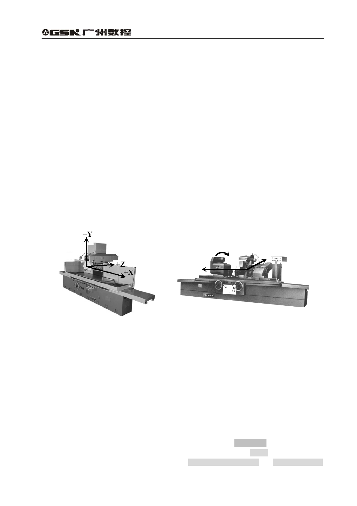
1.1.3.1 The differences between the coordinate systems
Based on the Cartesian coordinate system, the coordinate system of GSK928GA CNC system is Y/Z
one, X is normally the hydraulic control axis without displaying the position; while the coordinate
system of GSK928GE CNC system is X/Z one. The coordinate system is shown as the following
figures:
+C
+X
+Z
Fig. 1-1 The machine coordinate system Fig.1-2 The machine coordinate system
of the surface grinding machine of the cylindrical grinding machine
Moreover, the outer grinding machine belongs to the rotational machine. The cross section of its work
piece is normally round, and the dimensions marked on the machining drawing are diameter and the
radius. For the user to edit the machining program based on the machining drawing of the part,
GSK928GE cylindrical grinding machine CNC system provides the radius and diameter programming.
However, the part drawing of the surface grinding machine doesn’t have the problem of the diameter
dimension, therefore, GSK928GA only provides the radius programming.
1.1.3.2 Differences between I/O interface definitions
About GSK928GA and GSK928GE, I/O interface definition corresponds to PLC address. The tool
clamp of the surface grinding machine is the electromagnetic chuck, while that of the outer grinding
machine is the head and tail stocks. Therefore, in PLC definitions, Head stock is displayed on the
status bar of GSK928GE cylindrical grinding machine CNC system, while Chuck is displayed on the
status bar of GSK928GA surface grinding machine; Head stock motor control and Head stock motor
3
Page 16
GSK928GA/GE Grinding Machine CNC System Operator’s Manual
alarm are defined in PLC of GSK928GE, while Electromagnetic chuck magnet control and
Electromagnetic chuck alarm are defined in GSK928GA, which are shown as the following figures:
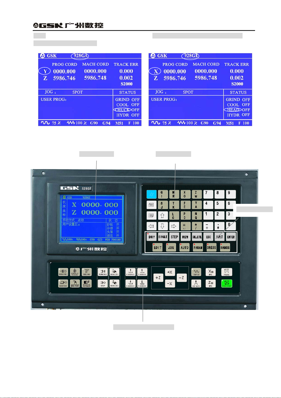
1.2 Introduction of system operation panels
Prompt screen
Address keypad
Function keypad
Fig. 1-3 Introduction of system operation panel
(1) LCD monitor: The top left part of the system is blue LCD, the resolution is 320 X 240 lattices,
which is for prompt of Chinese menu status of system, operational information and fault alarm.
Operation panel of machine
4
Page 17
GSK928GA/GE Grinding Machine CNC System Operator’s Manual
(2) Operation panel: The key is set, according to customer’s requirement, and control the machine
to finish the various accessorial function and basic operation;
(3) Address keys: English letter input of part program field address;
(4) Functional keys: Various graphic symbol function key is set according to CNN machine graphic
symbols;
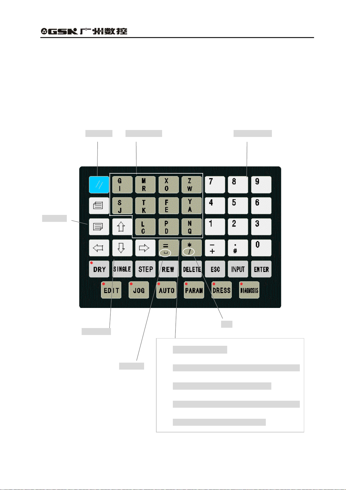
1.2.1 Introduction of the address keypad panel
Reset key
Address keys
Numerical keys
Page keys
Cursor keys
Space key
Skip
Double address key:
z Prompt the address code which is above the address
key when press this key at the first time;
Fig. 1-4 Address keypad panel
z Prompt the address code which is below the
address key when press the key again.
5
Page 18
GSK928GA/GE Grinding Machine CNC System Operator’s Manual
(1) Reset key
System reset key
All the movement of shaft stops when the system resets. All axis output function doesn’t
work, and the machine stops running and prompts electrified status.
(2) Page keys:
Page up:
Turn a page up to search the program or parameter in the Edit/Para (parameter) mode.
Change the type of displayed coordinate system in Auto/Jog mode.
Page down:
Turn a page down to search the program or parameter in the Edit/Para (parameter) mode.
Display/hide the follow error in Auto/Jog mode.
(3)Cursor control keys
The cursor moves upward:
Move the cursor to one upper row in the Edit/Para mode. The brightness of LCD is
enhanced in Jog mode.
The cursor moves downward:
Move the cursor to the next row in Edit/Para mode. The brightness of LCD fades in Jog
mode.
The cursor moves left:
Move the cursor to left in a character space in Edit mode. Delete the last input figures during
the status of data input.
The cursor moves right:
The cursor moves to right in a character space in Edit mode.
(4)Address key
Input the English letter of the part program field address.
6
Page 19
GSK928GA/GE Grinding Machine CNC System Operator’s Manual
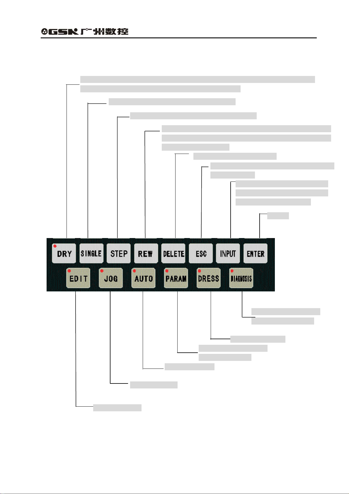
1.2.2 Introduction of the panel with function keys
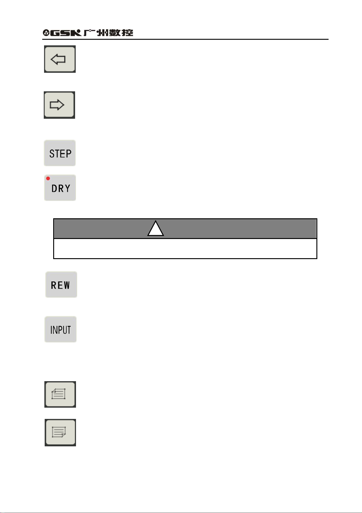
Select the dry run in Auto mode. The cursor can be directly moved to the initial
character of this line during editing the machining program.
In Auto mode, select single/continuous mode.
In Manual mode, switch between step and jog.
Switch the input mode (insert/rewrite) during editing the
machining program; In Auto mode, return to the initial line of
the machining program.
Delete the digit, letter or block.
Cancel the currently input various data or exit
from the mode.
Select the display or
setting para. mode.
Select Auto mode.
Select Jog mode.
Select Edit mode.
Fig. 1-5 Panel of function keys
Input the various data or select
the program to be edit or run and
create a new user program.
Confirm
Select the diagnosis
mode or program PLC.
Select Dress mode
7
Page 20
GSK928GA/GE Grinding Machine CNC System Operator’s Manual
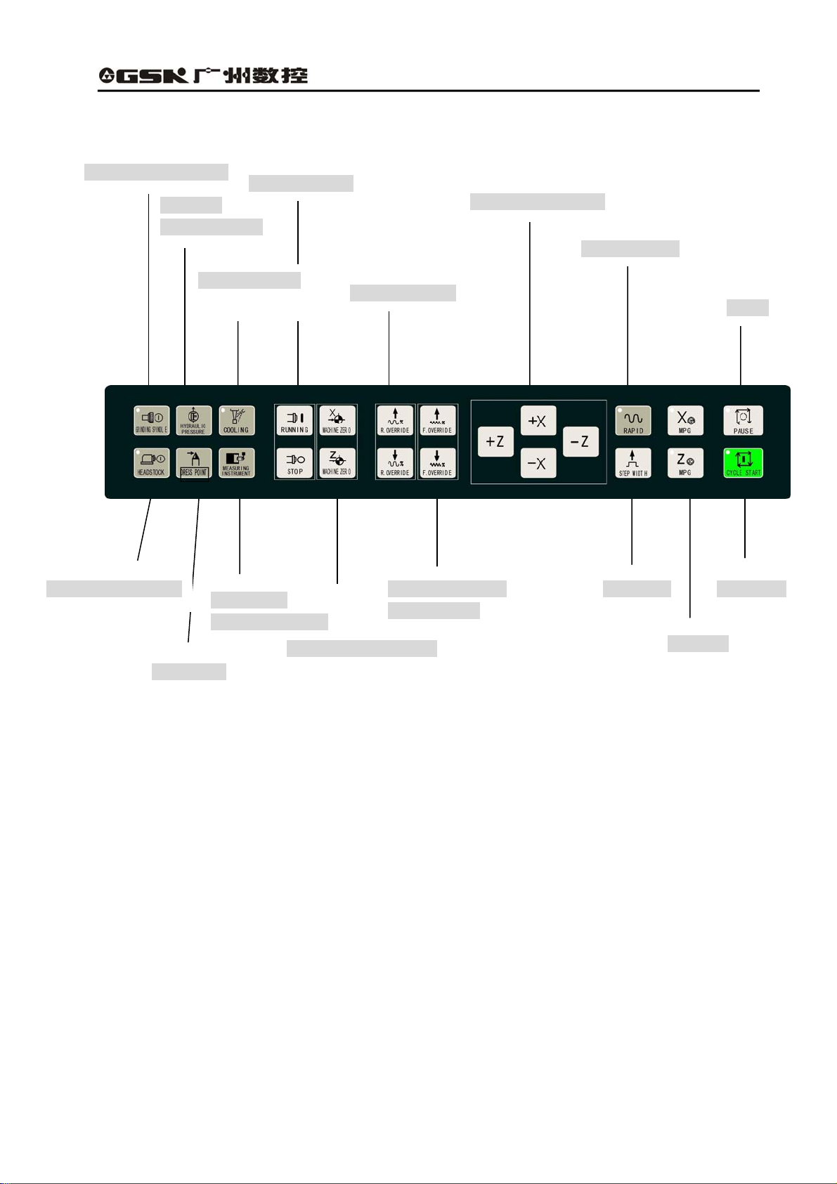
1.2.3 Introduction of the machine operation panel
Hydraulic
pressure switch
Cooling switch
Dress point
Spindle control
Measuring
instrument control
Mechanical zero return
Rapid override
Feedrate override
increase/reduce
Manual direction key
Rapid feed key
Pause
X/Z MPG
Grinding wheel switch
Machine-head motor Step width Cycle start
Fig. 1-6 Machine operation panel
8
Page 21
GSK928GA/GE Grinding Machine CNC System Operator’s Manual
CHAPTER 2 SYSTEM BASIC OPERATION
2.1 System power on/off
After connecting the external power supply, switch on the main power supply of machine. During the
situation, the machine is not started. Press the start button in the accessorial machine operation
panel of GSK928GE grinding machine CNC system and turn on the power supply of CNC system and
external drive. After system detects each configuration work is OK, then, the machine is allowed to
operate.
2.1.1 Power on
The steps of turning on CNC system:
1. Switch on the main switch of power supply, and turn on the system.
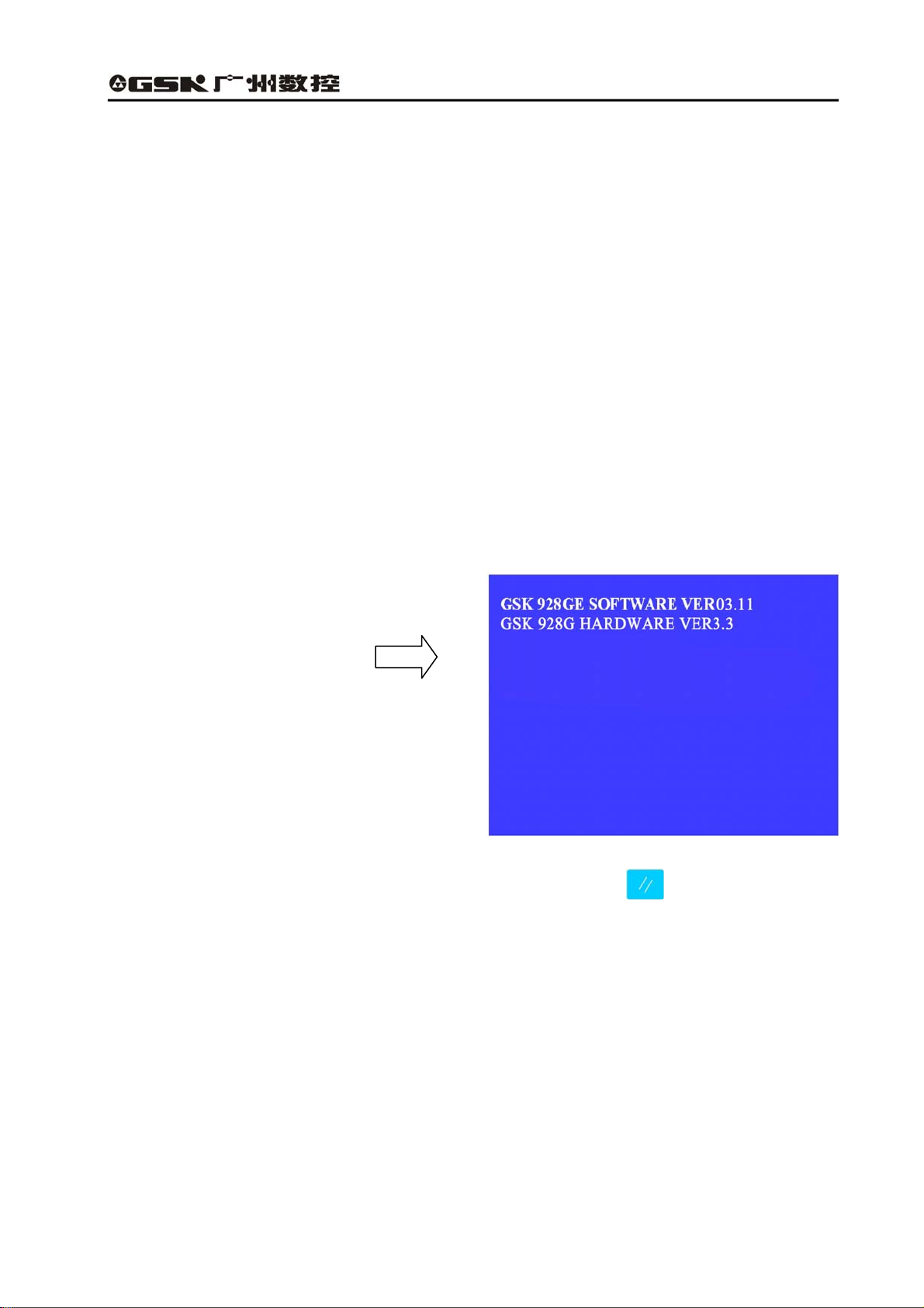
(1) System starting initialization
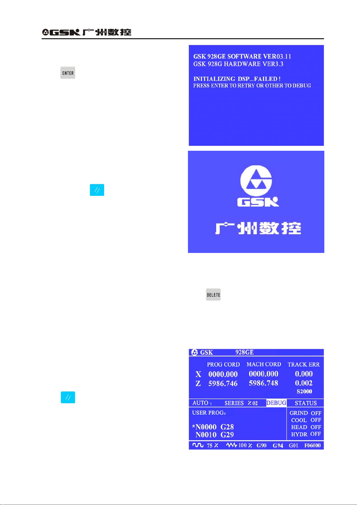
After switching on the system and initializing at the first time, the screen is displayed the version
numbers of software and hardware, which is shown in the right figure:
After initializing the system, the system checks PLC program. If PLC program is not correct, the
system shows the start-up screen and press any keys except reset key , the system comes into
debugging mode, then, the movement function does not work. If PLC program is OK, the system
starts initializing DSP.
(2)DSP initialization
After the system initializes at the first step, and PLC program is normal, it initializes DSP, if it is normal,
and the screen is displayed “INITIALIZING DSP……OK!”
The start-up screen prompts when finish starting the system.
9
Page 22
GSK928GA/GE Grinding Machine CNC System Operator’s Manual
If DSP initialization fails, the screen shows:
Press , the system tries to initialize DSP
again. Press other key, the system comes into
debugging mode and shows the start-up screen.
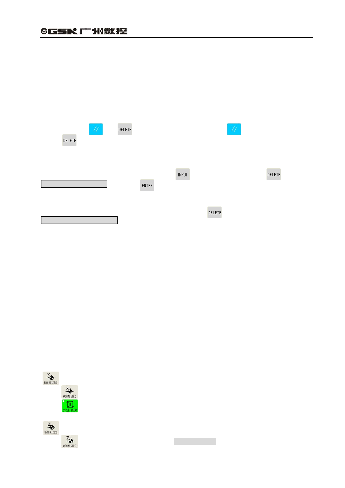
2. After system finishes initializing, the screen
Shows the trademark of GSK, and press any key
except reset key , the system comes into
working mode.
2.1.2 Debugging mode
If any mistake in PLC program or failure of DSP initialization at the start stage, the system enters
debugging mode. When emergency stop alarms, press for 5 seconds, the system enters
debugging mode. The movement function of the system does not work in the debugging mode, and
the system can not execute the relevant operation regarding to movement. The user can debug the
system, find the fault, and modify the parameter, the machining and PLC programs. In Jog/ Auto
mode, the system reminds the users that the system enters debugging by displaying the “debugging”
in the status bar under the working mode.
As above figure shows, in the debugging mode,
the user can modify PLC program in the
diagnose mode. After detection of PLC program,
press and restart the system, it enters
working mode.
10
Page 23
GSK928GA/GE Grinding Machine CNC System Operator’s Manual
2.1.3 Power off
(1) Press the switch of CNC power supply, cut off power supply, and the system turns off.
(2) Cut off the machine main switch of power supply.
2.1.4 Initializing CNC system
If power on the system at the first time, the initialization is operated according to the following steps:
Press and hold and at the same time, first release , after 3 seconds, then
release , the system completes the parameter initialization. Then, the parameter of the machine
is set as internal initialization of CNC system; refer to introduction of parameter about the details.
Initialization of system space:
●If the password is right, enter Edit mode, press and input “-01”, then press , it reminds
Sure to delete program? And press to specify.
Initialization of system PLC:
●If the password is right, enter diagnosis state, then press for two seconds and it reminds
PLC initialization completes!
2.2 Machine zero return (HOME)
Every machine sets one point as its zero point. After power on or reset each time, the worktable can
return to the zero point of machine, and return to the machining start point, then, the cumulative errors
are eliminated. The worktable returns to the machine’s zero point before machining, then, specify the
start point of machining and record the coordinate system of the machining start point which was
recorded last time. After power off each time, the machine returns to the zero point and then comes to
the machining start point which was recorded last time; finally, the program starts. Therefore, it can
avoid the situation that the system coordinate system is not consistent with the actual position which
may be moved by the operators after power off, and the accident may occur if the program starts
without specifying the machining start point after power on the machine.
The function is that “whether it must return zero after CNC system power on, again or resetting, and
then execute machining through selecting the parameter. Regarding to the details, refer to Bit 4 and 5
in the parameter 3.
Return to zero point of machine X axis
Press in Jog mode, the system prompts “X back to zero?”
Press , X axis rapidly returns to the machine zero point at rapid feedrate which is set in the
parameter.
Return to zero point of machine Z axis
Press in Jog mode, the system prompts “Z back to zero?”
11
Page 24
GSK928GA/GE Grinding Machine CNC System Operator’s Manual
Press , Z axis returns to the machine zero point at rapid speed which is set in the parameter.
Regarding to the method and process of the return to machine zero point, refer to 6.1.5.1.
1. The movement direction of machine returning to zero point is set by parameter Home
Polar X and Home Polar Z of parameter P041. The grinding wheel base should be kept at
the reverse direction of the switch during machine returns to the zero point.
2. Without the reference position switch on the machine, do not use the function of machine
returning to zero function, otherwise, accident may occur because the grinding wheel base is
moving at the high speed all the time without switch for reducing the speed.
3. Pay attention to it that during the machine return to zero, firstly the machine tries to return
the X axis where the grinding wheel motor is installed and the switch should be fit in the other
side which is far away from the Z axis work table.
!
REMARK
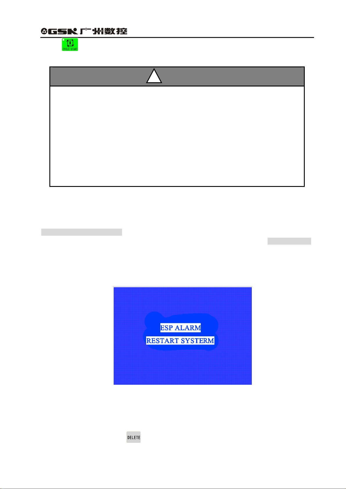
2.3 Emergency stop
There is an external emergency input port in the system input interface. The user should connect the
normally closed contract point, which is on the emergency stop of the red mushroom on the machine
panel, with the emergency input port. In the emergency situation, please press the emergency stop,
the system enters emergent status; all the feeds stop, and the spindle of grinding wheel, switching
value control and so on are edited by user through PLC. For safety, spindle and relevant equipment
are closed. About the editing mode, refer to some chapters of PLC program section. The screen
flickers and prompts as the figure 2.1 shows:
Fig. 2-1 Emergency stop alarm
Rotate the emergency switch according to the direction of an arrow, the emergency stop button
automatic springs up, then, press the reset key and restart the system, the system can come back to
the normal working status. If the system has no external emergency stop button, when the
emergency stop alarms, press for a while, the system can enter the debugging mode. Then,
modify PLC program, take the inverse value of the emergency stop signal and restart the system.
12
Page 25

GSK928GA/GE Grinding Machine CNC System Operator’s Manual
2.4 Alarm
2.4.1 Limit switch alarm
The system can check limit switches if the machine has installed. When the socket is moved and the
limit switch is pressed, the feeding stops but other miscellaneous function is still on, the program
stops running, and the grinding wheel spindle and switching value control and so on are set by the
user through PLC editing. When it alarms, the limit switch alarm information of corresponding axes is
displayed at the top right corner.
After the limit switch alarms, Jog mode can be selected. Press “cancel limit”, meanwhile, press the
manual feeding key or enter MPG operation, which is opposite to the limit direction, then, exit the limit
and the limit switch alarm automatically exits from the screen.
2.4.2 Software limit alarm
The system sets the limit range, and if the machine exceeds the setting value, the system reminds
axis software limit alarm, at the same time, press “limit release” and the corresponding direction keys,
it moves again. If it still exceeds the limit setting value, the machine can not respond in the exceeded
range.
2.4.3 Emergency retraction alarm
Using axis emergency retraction function can solve the problem of emergency retraction, and cancel
the alarm by releasing the limit key.
2.4.4 Drive unit alarm
When the alarm output signal of drive connects with CNC system and drive alarms, the system cuts
off all feeding operation automatically, and the screen also prompt X axis drive alarm or Z axis drive
alarm. The system stops running and closes the entire output signal which is specified by PLC.
Please check the drive and relevant connection,shoot trouble and switch on again.
2.4.5 Other alarms
It prompts in the screen in Chinese if CNC system alarms, and then it can be dealt with based on the
message. When many alarms occur at the same time, the system prompts in interval of 3 seconds,
and also calls the alarm information through pressing page down key in the diagnosis mode, and it
can save the latest 8 pieces of information.
13
Page 26

GSK928GA/GE Grinding Machine CNC System Operator’s Manual
2.5 LCD brightness adjustment
The brightness of GSK928GE CNC system LCD can be adjusted by keys to reach the best visual
effect. The method is as below:
(1) Switch CNC system to Jog mode.
(2) Press , the brightness of LCD screen becomes brighter or darker, and the result is
locked automatically. After the system power on again or reset, the brightness of LCD screen is kept
the same state before power off.
(3) If the temperature of environment changes obviously, the specialty affects the brightness of LCD,
which is not the fault of CNC system. And the same brightness adjustment may cause different effect;
therefore, it requires readjustment to reach the best effect.
14
Page 27
GSK928GA/GE Grinding Machine CNC System Operator’s Manual
CHAPTER 3 EDIT MODE
3.1 Edit mode
The Edit mode is to manually input or rewrite the part program through system operation panel. In the
Edit mode, the part program can be created, chosen or deleted through keypad; also, the selected
part program content can be inserted, edited or deleted. Moreover, via the RS232 communication
interface can connect with the serial interface of universal PC, then, transmit the part program of
system to the external computer, vise versa.
When the user edits the program, the system checks the right of user. The user possesses the right to
edit the program. The user can input correspondent password in the Para mode to change the right of
the user. Otherwise, the screen prompts User has no right!
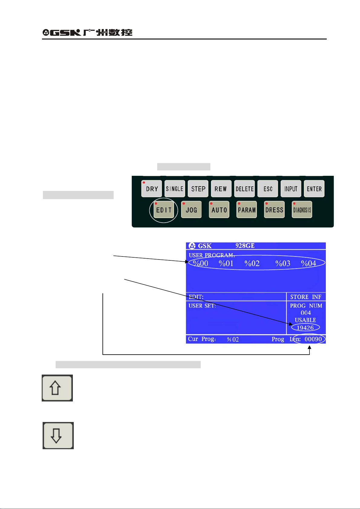
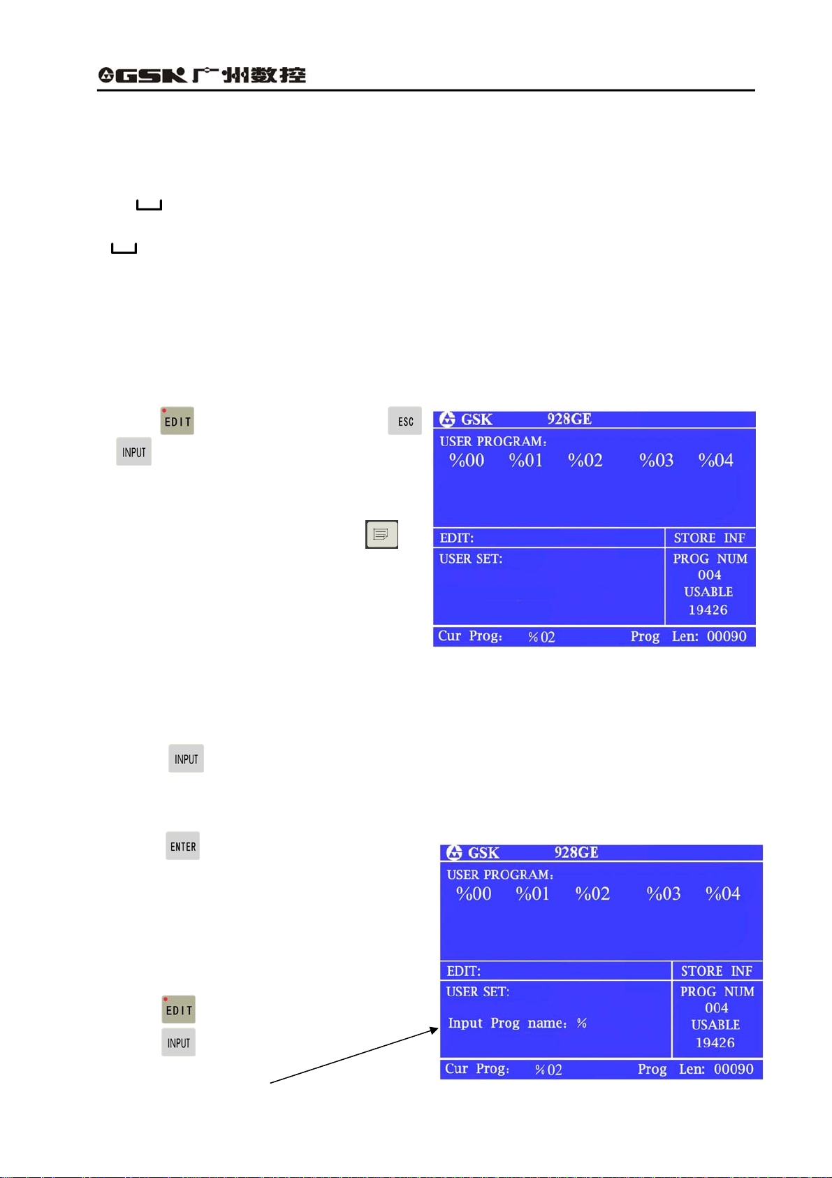
● Press Edit mode key
z Edit mode interface
a. All the present registered part program
names;
b. Usable memory bytes;
c. They bytes for the present program.
The meaning and usage of EDIT key in Edit mode:
Cursor moving upward key:
Press the key each time, the cursor moves to the first character behind last block number.
Press the key without releasing, the key continuously moves up till the first program line;
otherwise, the key is released.
Cursor moving downward key
Press the key each time, the cursor moves to the first character of next program row.
Press the key without releasing, the key continuously moves up till the last program line; otherwise,
the key is released.
15
Page 28
GSK928GA/GE Grinding Machine CNC System Operator’s Manual
Cursor moving to left key
Press the key each time, the cursor is moved by one character to left side. Press the
key without releasing, the cursor continuously moves towards the left side until the first
character of the same program line, otherwise, the key is released.
Cursor moving to right key
Press the key each time, the cursor is moved by one byte to right side. Press the key
without releasing, the cursor continuously moves toward the right side until the first
character of the same program line, or the key is released.
The cursor moves to the end of the program line.
The cursor moves toward to the first letter after program number.
Cursor—the symbol that shows the character which can be edited at present.
Insert/rewrite key
The key is for changing the edit input mode. Press key for each time, the input method
is switched between insert and rewrite, and the cursor prompt changes correspondingly.
The cursor of inserting is a flickering short line and the cursor of rewriting is a flickering square shape.
Input key
Press input key each time, and it inputs the program number in two digits, the new
program can be created, selected, or the exist program and all programs can be
deleted.
Page up
It prompts the content of last page when searching the list of program number.
!
REMARK
Page down
It prompts the program content of next page when searching the list of program
number.
16
Page 29
GSK928GA/GE Grinding Machine CNC System Operator’s Manual
Double function definition key:
Each key has two definitions, press the key for the first time, then it is the first definition value, that is
G M X Z S T F Y L P N = * — ﹒. Press the same key for the second time,
system changes into the second definition value, that is I R O W J K E A C D Q #
/ + . If the same key is pressed continuously, the input value is changed from the first
definition value to the second one or the second to the first. Among them, the “/” is skip block key,
“ ”is space key. But under special working mode, if the key has one definition, then the key is
switch to single function key automatically.
3.2 Part program directory search
Through part program directory searches, the users can search all stored part program number, and
the remaining bytes of the part program storage and all part program name list in the Edit mode.
(1)Press in the editing mode or press
or during program edit.
(2)Each screen can prompt 20 program names.
When the part programs of storage exceed 20,
it can prompt by pagination. Then, press ,
and turn to the next page, it prompts the list of
program numbers in the next page.
3.3 Part program management
3.3.1 Creating a new part program
(1) Press under the status of part program directory search;
(2) Input program numbers of two digits from keypad, which does not exist in the directory list, as new
program number;
(3) Press ;
(4) After creating the new part program, the system
enters program edit state automatically.
For example:
Create No.%19, which is new program number.
a. Press and enter Edit mode;
b. Press , the screen is displayed
Input prog number: % ;
17
Page 30
GSK928GA/GE Grinding Machine CNC System Operator’s Manual
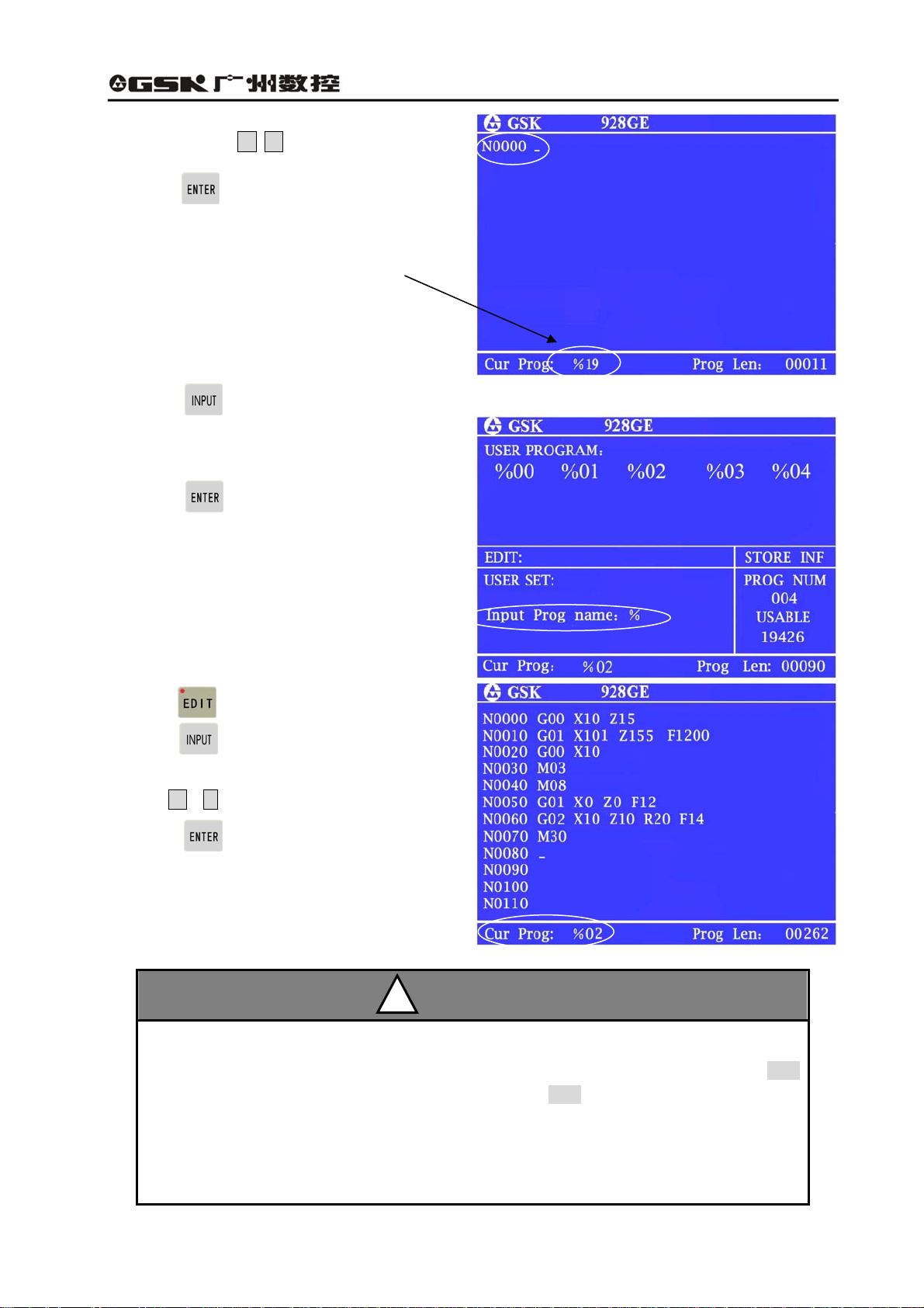
c. Press digit key 1 9
d. Press , No. %19 program number is
created. Block number is generated automatically
Current program number is displayed: %19
3.3.2 Selecting a part program
(1) Press under the status of part program directory search;
(2) From keypad, input the selected program
number;
(3) Press ;
(4) After selecting the part program, and prompt
the content, then, it enters Edit mode.
For example: select No. %02 program
a. Press and enter the Edit mode;
b. Press and screen prompts Input prog
%
number:
c. Input 0 2 ;
d. Press , program number % 02 is
selected.
;
!
REMARK
1. CNC system is powered on for the first time, it enters the Edit mode or system part
program storage area without any content, then, the system creates and selects %00
automatically. After system initialization, it also chooses %00 as present program.
2. After system selects one program, the program can only be changed through part
program selection. Once the program is selected, it always keeps same. Even power is off,
the program number can not be changed.
18
Page 31

GSK928GA/GE Grinding Machine CNC System Operator’s Manual
3.3.3 Copying a part program
Copy the present content of file to other one, and select the new files as present one.
(1) Press , the screen is displayed Input prog number: %
(2) Input the file name which does not exist in the file list, press , and all the content of current
file is copied into the file with the new name and the new file become current one.
For example, copy the current %02 into the file of %05 program.
Press , and input 0 5 , and press , the copy is completed.
If the input file name exists, the system prompts Name repeat! Press any key exit, and input
the file name again, which does not exist in the file list, and press .
!
REMARK
3.3.4 Renaming a part program
Rename the current file name.
(1) Press , the screen prompts Input prog number: %.
(2) Input the file name which doesn’t exist in the file list, press , and rename the current file
name.
For example: Rename the current % 02 file as %05.
Press , input 0 5 , press , renaming is completed.
3.3.5 Deleting a part program
(1) Press under the state of the part program directory searches;
(2) From keypad input the program name which is required to delete;
(3) Press , the screen prompts Sure?
(4) Press to delete the part program
which has the program number and press
to cancel the deleting operation.
For example: delete No. %05 program.
Press , input 0 5 , and press
and to delete %05 program from
part program storage.
19
Page 32

GSK928GA/GE Grinding Machine CNC System Operator’s Manual
The methods of copy, renaming and deleting are displayed on the screen:
① Press and enter Edit mode.
② Press and the screen prompts Input prog number: %.
③ Press 0 5 ;
RENAME
DELETE
(1)After copy, the screen is displayed:
No. %05 program is same as No. %02 one.
COPY
(5) After renaming, the screen prompts %05
program during the Edit mode.
No. %05 program replaces %02 one.
(3)During deleting, the screen is displayed:
Press , No. %05 program is deleted.
20
Page 33

GSK928GA/GE Grinding Machine CNC System Operator’s Manual
3.4 Inputting and editing a part program
CNC system machining is that the system automatically completes machining parts according to the
part program sequence input by the users.
Each program consists of some blocks; each block is composed by components of sequence number,
commands and data, etc. By inputting the part program content based on the processing sequence,
the machine can be started to machine the qualified parts.
3.4.1 Automatic generating the serial number
Each part program includes many blocks; each block is begun with a block number of .
When a new program is created, the system automatically generates the first number N0000.
Press , after inputting a block, then, the system automatically generates the next block number.
During input, the number increment depends on the content of P061 parameter. While inserting
blocks, the system automatically generates the block number based on integral part of 1/4 parameter
P061 content.
When use the jump instruction, the program line which is specified by P should be the only one;
otherwise, the same program line number may cause the jumping mistake.
The sequence of number generation and insertion of program line is as below: (the value of P956 is
10)
Automatic generation of
number (P061)
Insert program
line (1/4 of P061)
N****
3.4.2 Inputting the program content
The editing mode of CNC system adopts the full
screen. The input of program content is in the
editing mode.
(1)Create a new program as creating a new
part program;
21
Page 34

GSK928GA/GE Grinding Machine CNC System Operator’s Manual
(2)The monitor prompts the number N0000;Insert one line of program content through keypad.
(3)After input one line of program, press , complete inputting of the line. The system generates
the next block number, and then continues to input the program content.
(4)Repeat operation of the(3)step until the last line of program. Press and complete the input
of program content. If any mistake in editing, the system alarms. Then Press again; it exits the
edit interface.
Prompt the program ends without
end command of M02.
Each block only prompts 38 characters. It just prompts the leading 38 characters of the block
if exceeding 38 characters. Press , it prompts a character of the block to the right side.
But each line can not include more than 255 charactes, otherwise, the system does not
accept the content any more. The monitor can prompt 12 lines of program, it automatically
moves upward if more than 12 lines.
!
REMARK
3.4.3 Inserting a program line
Insert one or multiple program lines between two program lines.
(1) Press and move cursor to the first block between two blocks.
(2) Press until the cursor moves behind the last character, or press and move the cursor
directly to the last character.
(3) Press , the system automatically generates number of a new block between two blocks and
leaves one blank line. The number increment is 1/4 integral value of P061 parameter, if it is not
enough, then the next line number can be rewritten.
(4) Input the block content to be inserted;
(5) After inputting all the content; press if multiple program lines should be input. If there is one
program line, the operation is not required.
(6) Inserting the block is over.
22
Page 35

GSK928GA/GE Grinding Machine CNC System Operator’s Manual
1. Insert the block behind the last one and press and it automatically generates the next
block number.
2. Before the first program line, it is not allowed to insert block. If it requires inserting block before
the first line, rewrite the content of the first line into that of the line to be inserted, and insert the
original first line into this program line.
For example: Insert the new block M3 between blocks N0020 and N0030 .
(1) Press and move the cursor to
N0020 .
Press and move the cursor behind X50.
!
REMARK
(2) Press , the system automatically generates new program line number and leaves one blank
line to prompt N0022 . The cursor points to the first character, which can be input, of the new
program line.
Input M 3 。
(3) Press and finish inserting operation.
3.4.4 Deleting a character or a block
Delete the character of one program line or the whole content of program line including the serial
number.
(1) Press and move the cursor to the block which requires deleting;
(2) Press and move the cursor to the character which should be deleted; if delete the block of
the whole line, move the cursor to the beginning of block to be deleted.
(3) Press and delete the character which is pointed by cursor. If the cursor is at the line
beginning of block, then the block of the whole line is deleted.
23
Page 36

GSK928GA/GE Grinding Machine CNC System Operator’s Manual
3.4.5 Inputting a field in a block
(1) Specify whether the current input is inserting; if it is not, press and switch the input to
inserting;
INSERT
(2) Press or and move the cursor
to the position that is after the character and should insert the content;
(3) Input the content which should be inserted, and insert the content before the character which is
pointed to by cursor.
For example: In N0020 G0 X50,
insert 1 between X and 5.
REWRITE
Because CNC system requires each filed of program line must be partitioned by space,
which is one letter followed with digits. During input, the editing program can automaticly
judge and generate the space. However, during the inserting Operation, sometimes, the
system can not judge automatically sometimes. Therefore, the operator should input by
himself the space to gurantee the intergrity of the program.
REMARK
!
24
Page 37

GSK928GA/GE Grinding Machine CNC System Operator’s Manual
3.4.6 Rewriting the content of a block
Change the content of a block into a new one. There are two methods as options based on the input:
insert or rewrite.
In insert mode, use inserting and deleting to complete it.
(1) Press , move the cursor to the character which should be rewritten;
(2) Insert new contents;
(3) Delete the surplus content through the same operation which is used for deleting the block
content.
In rewrite mode, directly rewrite the content which is pointed to by the cursor.
(1) Press and switch the input mode to rewrite mode, and the character which is pointed to by
cursor is bright square shape.
(2) Press and move the cursor to the character which should be rewritten.
(3) Input new content, the cursor points to the next character.
For example,
Change N0050 X10 to X120
In insert mode:
(1) Move the cursor to X10, below 0.
(2) Input 2
(3) Move the cursor to X120, which is below 1 ;
(4) Press , then, X120 is changed to X20.
25
Page 38

GSK928GA/GE Grinding Machine CNC System Operator’s Manual
In rewriting method:
(1) Press and change the input mode to rewrite mode, and the character pointed to by cursor is
displayed in bright square shape.
(2) Put the cursor above 1 of X10.
The character selected prompt as
bright square shape.
(3) Insert 2, it is changed to X20.
3.4.7 Skipping a block
Insert a sign of / before number N of a block.
During executing a program, the system skips
this block and executes the next one.
(1) Switch the input mode into the insert one.
(2) Move the cursor to the block which should be
skipped, and press to the block, which is
below N ;
(3) Continuously press , and insert the
character / before N;
(4) When complete programming, if it encounters the mistakes of program during exit, press for
the next operation!
26
Page 39

GSK928GA/GE Grinding Machine CNC System Operator’s Manual
3.5 External inputting a part program
Input the part program which is stored in the external computer into CNC system.
(1) After power off, connect the communication
cable between CNC system and computer;
(2) CNC system is switched on and
select the Edit mode;
(3) Press and it prompts Receive ready!
(4) Specify the system is ready, press ,
it prompts Receiving……, and the program of
the external computer is input into CNC system;
(5) Set the communication software of computer to the output mode;
(6).After receiving, it prompts Receiving is over! Press and come back Edit mode. In the list of
part program, it prompts the input program name by ascending sequence.
(7) During receiving, press to terminate the receiving process.
During part program input, if CNC system has the same program number, the system
reminds Same program name, then change or delete the program name, the
communication works again.
!
REMARK
3.6 External outputting a part program
Send the part program stored in CNC system to the external computer.
(1) During power off,connect CNC system with
computer through communication cable.
(2) CNC system is switched on and selected Edit
mode;
(3) Select the part program which should be sent
by the operation of selecting the part program;
(No option if send the current programs)
(4) Press , it prompts Sending ready!
(5) Set computer as the status of receiving.
27
Page 40

GSK928GA/GE Grinding Machine CNC System Operator’s Manual
(6) Specify the external computer ready, press , and it prompts sending……, the selected
program is sent to the external computer.
(7) After sending, it prompts Sending is over! Press and return Edit mode.
(8) During sending, press and terminate the sending.
3.7 Deleting all part programs
Delete all programs in the storage of CNC system.
(1) Press in the status of part program directory researches.
(2) Input - and 0 from the keypad;
(3) Press , the system prompts Confirm delete?
(4) Press and delete all part programs,
If is pressed, the deleting operation is not executed and come back to Edit mode.
28
Page 41

GSK928GA/GE Grinding Machine CNC System Operator’s Manual
CHAPTER 4 JOG MODE
4.1 Overview of Jog mode
Press , the machine comes into Jog mode.
During Jog mode, press , the two methods of Jog and Step can be switched.
Press MPG key or , it comes into MPG mode; meanwhile, the coordinate axes which are
controlled by MPG are selected. Through keypad, it can operate the movement of worktable and
movable socket of grinding wheel, start and stop spindle of grinding wheel and cooling fluid,
adjustment of feed override and the function of X axis machine returning to home position.
The system initialization mode is Jog mode, as
the following figure shows::
4.1.1 Manual operation
(1) Select Jog mode;
(2) Press , select Jog mode. The maximum movement distance of each continuous pressing
same key is 1000.000mm.
(3) Press one direction key, the work table or the movable socket of grinding wheel moves in the
direction of selected coordinate axes. Press the key without releasing, the worktable or the socket is
moved continuously. Release the key, the socket or the worktable decelerates and stops.
29
Page 42

GSK928GA/GE Grinding Machine CNC System Operator’s Manual
Z axis positive direction
Z 轴正方向
4.1.2 Manual step operation
(1) Press and select Step mode.
(2) Press and select the step.
X axis positive direction
X 轴正方向
X axis negative direction
X 轴负方向
Z axis negative direction
Z 轴负方向
(3) The steps are divided into 6 levels: 0.001, 0.01, 0.1.1.0, 10.0 and 50.0, press the key for one time,
the step increases by one level, and it switches in circulation.
(4) Press , the worktable and movable socket of grinding wheel is moved in the selected
direction of coordinate axis by the chosen distance of step. Press one direction key without releasing;
it is moved one level of step.
!
REMARK
Press and stop moving in Step mode.Press the key, the worktable and the socket of
grinding wheel decelerates and stops, the remaining step is not kept, and press feeding key
to execute the next feeding process of single step.
30
Page 43

GSK928GA/GE Grinding Machine CNC System Operator’s Manual
4.1.3 MPG operation
In MPG mode, the movement of worktable and movable socket of grinding wheel can be controlled by
turning the manual pulse generator (MPG).
(1) Select MPG axis or , it enters MPG mode.
(2) Press and select the moving distance.
● There are three options of circulation switches: 0.001、0.01、0.1mm
● When the working mode is switched from Step mode into MPG, the move distance value of each
scale is automatically selected as 0.010mm.
(3) Running MPG.
● CW running, the coordinate axis moves
in the positive direction;
● CCW running, the coordinate axis moves
in the negative direction.
During MPG mode, other function key on axis move are not working, such as jog, return to
home positon, relative and absolute movement, but other M accessorial functions are still
valid.
!
REMARK
4.2 Selecting the manual feedrate
In the manual feeding mode, there are two selections that include the override of manual feedrate
and manual rapid override.
Selecting
rapid overrides
Selecting
feedrate overrides
Selection between speed
override and rapid override
31
Page 44

GSK928GA/GE Grinding Machine CNC System Operator’s Manual
4.2.1 Selecting manual feedrate overrides
Select the feedrate override in Jog mode.
Feed rate override increases 1%.
Feed rate override reduces 1%.
In Manual feeding mode, press and rapid indicator is OFF, the screen prompts as below:
For example:
The feedrate F is 6000, and selective speed
override 80%, then the actual feedrate is
6000*80%=4800.
Feedrate override
4.2.2 Selecting manual rapid feedrate overrides
The rapid mode is selective in manual feeding mode. During rapid feeding, the speed is selected by
override.
In manual rapid feeding, the actual feedrate depends on rapid traverse speed and override:
X axis actual rapid speed = P005 X rapid override
Z axis actual rapid speed = P006 X rapid override
In Manual Feeding mode, press and select the manual rapid feeding mode, then the indicator is
ON, the feedrate and rapid override are displayed as bright square shape, and the screen is shown
as below:
32
Page 45

GSK928GA/GE Grinding Machine CNC System Operator’s Manual
4.2.3 Manual setting feedrate F
In Jog mode, it can set the feedrate in Jog and Auto modes by inputting the feedrate F. The method is
as below:
a) Select Jog mode;
b) Press , then, F shows brightly, in the rapid parameter range of X and Z axes, any digit
between 0000.000 and 8000.000 can be input.
c) Press , the feedrate value is the input digit value on the screen; Press , then the
feedrate doesn’t change.
For example, manually input F3000
(1) Select Jog mode and input F3000, then, the
feedrate F in the information prompt bar is
“6000”.
(2) Press , the feedrate F
is changed into 3000
When the coordinate axes are stable, the speed value F shown in the information prompt
bar is setting value. When coordinate axes are moving, it is feedrate value of moving axes
and fluctuates in the range. When many axes move rapidly, the system prompts the speed
value as their minimum value.
!
REMARK
4.3 Setting a workpiece coordinate system
GSK928GE CNC system uses the floating workpiece coordinate system, which is equivalent to the
program coordinate system. Workpiece coordinate system is the benchmark of tool setting and its
33
Page 46

GSK928GA/GE Grinding Machine CNC System Operator’s Manual
dimensions. After finishing the installation of system, firstly, the workpiece coordinates should be set
up. If the machining steps out for some special reasons, the actual position and workpiece
coordinates can not comply with each other, and then the workpiece coordinate system should be set
again. The operation of setting workpiece coordinate system:
(1) According to the requirement of machining, move the grinding wheel to the setting point of
workpiece coordinate system.
(2) Press , the screen prompts Set , then press X, the screen prompts set X , input the
coordinate system value at the workpiece coordinate system of X axis direction. Press , the
system prompts Specify input? Then press and specify whether the system has already
automatically set the workpiece coordinate system of the X axis direction or not and refresh to display.
Press , the workpiece coordinate system setting of X axis is canceled. If the input data is wrong,
press and delete one by one, rewrite and input again.
(3) Press , the screen prompts set , then press Z key, it prompts set Z , input the workpiece
coordinate value at Z axis direction. Press , the screen prompts Specify input?
Press and specify whether the system has already set the workpiece coordinate system of the
X axis direction and refresh to display. If press , the workpiece coordinate system setting of Z
axis is canceled. If the input data is wrong, then press and delete them one by one, rewrite and
input again.
(4) When the program coordinate system needs fine setting, firstly press , the screen prompts
set, select the coordinate axis X or Z which is required fine setting, input the value of increasing or
reducing, and then press and specify and refresh the screen.
Through the above operation, the workpiece coordinates of system can be created and
completed. After initialization of system, the workpiece coordinate system must be set.
!
REMARK
34
Page 47

GSK928GA/GE Grinding Machine CNC System Operator’s Manual
4.4 Manual input movement control
In Jog mode, the axis movement is directly controlled by inputting the movement distance. The input
distance value is the target distance of program system coordinates. The operation is as below:
(1) Select the position axis X which should move directly and it shows as the following left figure:
(2) Manually input the target coordinates which is required to move X,
Press , then the screen prompts Specify operation?
If it is specified, press , the system automatically moves to the setting coordinate system value,
as the following right figure shows:
4.5 Manual measuring instrument control
In Jog mode, it may select measurer forwarding or retraction through manual keys based on the
requirement. The system panel not only provides an instrument control button as radial control which
is default by the system, but also it can change the parameter 4 Bit 6 for control of end surface
instrument, also M commands can also control the forwarding or retraction of instrument.
Press , the instrument can move to the specified measuring position; Press the key one more
time, the instrument returns to the original position.
4.6 Manual grinding wheel spindle control
In Jog mode, the start and stop of the spindle axis can be controlled through keypad.
Press , the grinding wheel starts running, the screen prompts the status of grinding wheel: ON,
meanwhile, the LED indicator is also ON.
Press again, the grinding wheel stops running, the screen prompts the status of grinding
wheel: OFF, meanwhile, the LED indicator is also OFF.
35
Page 48

GSK928GA/GE Grinding Machine CNC System Operator’s Manual
4.7 Manual machine-head control
In Jog mode, the start and stop of machine-head can be controlled through keypad.
Press , the machine-head starts, the screen prompts the status of machine-head: ON, at the
same time, the LED indicator is ON.
Press again, the machine-head stops running; the screen prompts the status of machine-head:
OFF, at the same time, LED indicator is OFF.
4.8 Manual hydraulic pressure control
In Jog mode, the start and stop of hydraulic pressure can be controlled through keypad.
Press , the hydraulic pressure starts; the screen prompts the status of machine-head: ON.
And press again, the hydraulic pressure stops running, the screen prompts the status of
hydraulic pressure: OFF.
4.9 Manual cooling control
In Jog mode, the start and stop of cooling fluid can be controlled through keypad.
Press , cooling fluid starts, the screen prompts cooling status: ON; meanwhile the LED
indicator is ON.
Press , the cooling fluid is off, the screen prompts cooling status: OFF; meanwhile, the LED
indicator is OFF.
4.10 Manual spindle control
In Jog mode, the movement status of the second spindle can be controlled through keypad. Based on
the different control mode, the function of spindle control button may be different. About the selection
of control mode, refer to parameter Bit6 and Bit7. Under the servo spindle control circumstances,
according to the usage requirement, generally, press to manually control the switch of spindle
through clockwise signal or connecting or breaking the enable signal.
Normally, press , the spindle runs. Press and stop.
4.11 Manual inputting and executing M function
In Jog mode, M code command can be input and executed for the corresponding M function.
Normally, only input system is allowed to control output M code. The method is as below:
(1) Select Jog mode;
(2) Press M , M is shown brightly and then input one or two digits by numerical keys.
36
Page 49

GSK928GA/GE Grinding Machine CNC System Operator’s Manual
(3)Press , execute the corresponding M function; Press , M function is canceled.
For example, manually input M03 function
(1) Select Jog mode, input M03 .
Then, the grinding wheel in the status bar
is indicated OFF.
(2) Press , execute M03 and start motor of grinding wheel, the status of grinding wheel in the
status bar is ON.
The M code can be input manually: M03、M05、M08、M09、M10、M11、M12、M13、
M14、M15、M16、M17、M18、M19、M20、M21、M22、M23、M24、M25、M26、M27、
M28、M29、M33、M35、M46、M47、M48、M49、M50、M51、M70、M75、M78、M79.
REMARK
!
4.12 Manual inputting and switching into G state
G status which is input and switched includes the switches between programming status of
relative/absolute (G90/G91) and feeding status of per minute/per revolution (G94/G95).
About the details, after pressing , input the changed status (91—90 or 95—94), after specifying,
the corresponding status is automatic changed in the info. bar.
37
Page 50

GSK928GA/GE Grinding Machine CNC System Operator’s Manual
For example: manually input G91 to change program method:
(1) In the info prompt bar, the current
programming coordinate method prompts
“G90” (absolute coordinate program).
(2) In Jog mode, press , and then input
“91”, press and specify the mode
automatically changes into “G91” (relative
coordinate program) in info. bar.
4.13 System angular axis function in Jog mode
The function of the angular axis is for grinding and cutting of ladder shaft. The basic principles are:
1. Z and X axes are not vertical, the contained angel is α degrees. About setting degrees, refer to
parameter P051 and P052.
2. Use shaped grinding wheel to grind the external circle and end surface.
Grinding angular axis
38
Page 51

GSK928GA/GE Grinding Machine CNC System Operator’s Manual
There are two methods of angular axis feeding: the link between X and Z axes (M50), the
independent movement of X and Z axes (M51). The machine coordinate system of X axis machine is
the actual movement distance which the grinding wheel moves in the direction of angular axis, and
the workpiece coordinate of X axis is movement distance which the grinding wheel moves in the X
axis radial direction. During link, X axis moves and Z follows. But the workpiece coordinate of Z axis
remains unchanged, that is to say, the relative position of workpiece and grinding wheel in Z axis
direction remains unchanged, only the machine coordinate changes. When Z axis moves, X axis is
static, the workpiece coordinate system of Z axis and the coordinate system of machine changes
normally. Z and X axes move independently if they are not in the link.
(1) In Jog mode, input M50.
(2) Press , the angular axis mode, which is in the information bar, prompts M50, and it is
two-axis mode.
1. When system uses angular axis function (input corresponding angle), the
interpolation status in system prompt bar is changed to M50/M51.
2. The system defaults the angular axis mode as M50; it automatically sets M50 after
switching the interface.
3. The machine resets and returns to reference position, the link (M50) is automatically
canceled and returns to M51 status.
!
REMARK
39
Page 52

GSK928GA/GE Grinding Machine CNC System Operator’s Manual
CHAPTER 5 AUTO MODE
Press and enter Auto mode. In Auto mode, the system automatically executes the current
selected program and machines the qualified workpiece.
Auto mode is classified into machining and dry run which is machine lock mode.
The initializing interface of Auto mode is as below:
In machining mode, the system can run in single
block or continuous running.
5.1 Function key in Auto mode
Switch between single block and continuous running mode
Press this key each time, the running mode between single block and continuous
operation is switched for one time; meanwhile, the screen prompts the selected mode. When the
mode is single block and screen prompts single block. When working mode is continuous running and
screen prompts continuous running. During the continuous running, the single segment mode stops
after pressing this key, that is to say, this block completes and the execution of single block pauses
and it starts after pressing running key.
Switch between machine lock and machining
Press the key each time, Auto mode is switched between machine lock and machining for
one time. In the machine lock mode, press , LED indicator is on; in the machining
mode, LED indicator is off. In the machine lock mode, the program is running, but the coordinate axis
remains unchanged and the other machine miscellaneous functions are off.
Selecting the block number
Press this key and select the block which is required to run, press , the system
operates from the selected block.
40
Page 53

GSK928GA/GE Grinding Machine CNC System Operator’s Manual
Cycle start key
During the single block running, press the key for one time and one block is executed.
During continuous running, press the key and the program is executed from the beginning
to the end.
Feed hold key
During program running, press the key, then the coordinate system decelerates and stops;
the screen brightly prompts Pause! Press cycle start key, the remaining part of program is
continuously executed. Press , the remaining part is not executed.
After finishing dry run, the coordinate system automatically recovers the program coordinate
system value before dry run. The coordinate of machine always remains unchanged.
!
REMARK
5.2 Automatic running a machining program
In Edit mode, firstly select the program for automatic running, and switch to Auto mode, then the
system executes the selected part program to automatically machine the workpiece.
The initialized mode is continuous mode in Auto mode.
5.2.1 Starting from the first line of a machining program
After entering Auto mode, the system automatically prompts the machining program information of
three lines. And prompt symbol “*” before the running block number.
Press , the program automatic machining can start.
After the machining begins, the program in the first line is the block just ended, the second one is the
executing block, and the third one is the block to run.
41
Page 54

GSK928GA/GE Grinding Machine CNC System Operator’s Manual
5.2.2 Starting from the specified line of a machining program
Under some circumstances, it should start from any line of a machining program, and the current
program can start from any line and the grinding wheel can stop at any position. The steps are as
below:
(1)Determine the specified program line to start running.
● Press , the system can prompt the first
line of current running program.
● Press , the system prompts the
content of last block or next block.
(2) Press and prompt the block which is
going to run, the screen prompt Sure to run?
Then wait for the next operation.
(3) When the screen is displayed Sure to run? ,
press , the system automatically calculates
the coordinate position to be reached before
executing the block, and automatically move and
reach the position in previous mode. If
press , the system exits the selection and
prompts the original block.
The user can only select the block of main program; also check the block of subprogram,
which is not allowed to run. Press during checking the subprogram, then the dialogue
Please return to main program pops up, and then the user can not execute the subprogram.
!
REMARK
5.2.3 A machining program running in single block or continuous running
After editing the program, the single block mode can be selected to run for safety at the first time.
Press , the system automatically executes one block. Observe whether the running of machine
is compliant with the designed movement of program, and then decide the next operation.
If the machine is running normally, press and execute the program one by one until the
program finishes. If any block is not compliant with the movement of designed program, then the
42
Page 55

GSK928GA/GE Grinding Machine CNC System Operator’s Manual
running should stop, and return to the program reference position, find out the reason, and rewrite the
program until it is correct. Finally, select the continuous running mode and automatically machine the
parts.
Single block mode
(1) Press , the indicator is on, and the machine enters single block mode. In the middle of the
screen, it prompts single .
Press again, the indicator is off, and it returns to Auto mode.
(2) In the single block mode, press cycle start
key once and it executes one block; Press
again and it executes the next block.
(3) During executing the single block, press
, it is not working. However, the switch
between “SINGLE” and “CYCLE START” are
valid after the current command operation.
5.3 Dry run (machine lock)
After editing a machining program, the coordinate data and executing sequence of blocks can be
observed in the screen during dry run mode, and it may judge whether the machining path is correct
or not to avoid the mistake of program data input which may result in some consequence. If the
machine lock program is normal, it can be switched into the machining mode.
Press once, the running mode is switched between the machine lock mode and machining
mode for one time. When the machine lock mode is selected, the top left indicator of its key is on.
(1)Auto mode;
(2)Press , the indicator is on.
● The machine enters dry run mode.
● Press again, the indicator is off, and the dry run mode is off and it returns to Auto mode.
43
Page 56

GSK928GA/GE Grinding Machine CNC System Operator’s Manual
1. During the machine lock mode, the coordinate axis locks, and other miscellaneous
function output is invalid.
2. When entering Auto mode, the initialized mode is the machining mode;
3. During dry run, the system program coordinate changes, while the machine coordinate
remains unchanged and the machine doesn’t operate.
4. Dry run can also estimate correctness of the arc in advance.
!
REMARK
5.4 Checking the macro variable in Auto mode
During Auto mode, press and switch between the program page and macro variable page.
Check the macro variable of parameter directly.
The operation is as below:
(1) In Auto mode, the program doesn’t running or
dwelling mode;
(2) Press , the user program area prompts
the macro variable of floating point type;
(3) Press and turn over the macro
variable of floating point type.
(4) Press again; the user program area
prompts the macro variable of integral type.
(5) After prompt the macro variable of integral
type, press again, the page comes back
to the program dwelling position; press ,
then the program continuously runs.
5.5 Manual operating the machine miscellaneous function
During Auto mode, spindle of grinding wheel, machine-head motor, cooling fluid, hydraulic pressure
and the second spindle etc, the miscellaneous function can be operated manually without executing
the program. The cooling fluid control can be operated during program running.
44
Page 57

GSK928GA/GE Grinding Machine CNC System Operator’s Manual
z Press , the spindle of grinding wheel starts running, the screen prompts the grinding wheel
and LED indicator are on. If the spindle of grinding wheel is off, and the screen prompts that the
grinding wheel and LED indicator are off.
z Press , the machine-head motor begins running, the screen prompts that the machine-head
and LED indicator are on. When the machine-head motor is off, the screen prompts that the
machine-head and LED indicator are off.
z Press , the cooling fluid switches between on and off, the cooling fluid is on, the screen
prompts the cooling fluid and the LED indicator are on. When cooling fluid is off, the screen prompts
that the cooling fluid and the LED indicator are off.
z Press , the hydraulic pressure switches between on and off. When hydraulic pressure is on
and the screen prompts the hydraulic pressure is on. When the hydraulic pressure is off and the
screen prompts the hydraulic pressure is off.
5.6 Adjusting speed overrides
In Auto mode, when the speed override is changed, the movable socket of grinding wheel also
changes.
z Feedrate override: adjust the speed F setting value in the program
Actual feedrate F = system specified feedrate X feedrate override
Feedrate override totally has 151 levels from 0%~150%, all the control commands of feedrate is
controlled by feedrate override during execution. When feedrate override is zero, stop running.
z Rapid override: adjust the rapid traverse movement command of G00 and so on in the program.
X axis actual rapid speed= Parameter P005 X rapid override
Z axis actual rapid speed= Parameter P005 X rapid override
The rapid override totally has 100 levels from 1%--100%, and the interval is 1%. During the program
implementation, all the command and movement of rapid feeding are controlled by rapid override.
Press once, the feedrate override increases by one level until 150%.
Press once, the feedrate override reduces by one level until 0%.
Press once, the rapid speed override increases by one level until 100%.
Press once, the rapid speed override reduces by one level until 1%.
No matter whether the program is running or not, the speed override can be changed
through the above four keys.
!
REMARK
45
Page 58

GSK928GA/GE Grinding Machine CNC System Operator’s Manual
CHAPTER 6 SETTING SYSTEM PARAMETERS
The improper parameter setting may result in the loss of
the machine function or the wrong movement which may
hurt the operator. Before rewriting the parameter, please
read the chapter carefully.
There are many parameters in CNC system of GSK928GE, it adopts grouping method to manage the
parameter for the user to look up and rewrite the parameter conveniently. According to different
functions, the parameter is classified into nine groups, each parameter group has different
parameters and each parameter has clear definition. Parameter setting plays an important role in the
system specialty and machine function. During the installation and debugging of machine, the
corresponding parameter should be set based on the detailed setting of machine.
The parameter setting directly affects the running of system and machine directly, so it can not be
changed at random. Only the user who has the right to rewrite the parameter can change the
parameter. The users can input their own password to change the user’s right.
At the same time, 928GE also provides the system parameter and backup and restore function of
PLC program for user. Therefore, if the parameter or PLC programs are mis-rewritten, the users can
restore by themselves.
Press and enter the parameter setting
mode. The screen prompts nine submenus
of parameter and the range of parameter.
Through or , it can be switched
between the parameter and PLC backup and
operation interfaces.
46
Page 59

GSK928GA/GE Grinding Machine CNC System Operator’s Manual
Press and select the corresponding parameter submenu up and down, press and
enter the parameter submenu pages to check the parameter setting, or directly enter through the
number to check the parameters. The user can enter submenu by pressing or to turn the
pages forward or backward, and prompt other parameter and each page includes nine parameters
and press to select the parameter.
6.1 Introduction of parameters
After selecting the parameter number, the screen prompts the selected parameter number and name
brightly, and the setting range of parameter, the meaning of each parameter is as below:
6.1.1 User passwords
To prevent the situation that the program or parameters are falsely changed, the system sets the
user’s password. Different user’s password corresponds to different right of system operation. The
system operational rights are classified into three levels: machine manufacturer, programmer and
operator. Respectively, their rights are:
Machine manufactures: They can rewrite all parameter, PLC program and the machining program.
Programmer: They can rewrite the machining program and the parameter except for the pitch error
compensation and the password is: 928.
Operator: They can only rewrite the macro parameter, the password is: 0.
After setting user’s password, it remains unchanged without rewriting. After the user changes the
parameter or rewrites the program, the password should be set as initialization value, and guarantee
the program or the parameter is not mis-written. After power on or resetting each time, the
initialization value is defaulted as 0.
47
Page 60

GSK928GA/GE Grinding Machine CNC System Operator’s Manual
6.1.2 Movement parameters
The parameter is mainly to control the movement of X and Z axes, including the rapid speed,
maximum travel limit and time of acceleration and deceleration, etc.
6.1.2.1 Parameters P001 and P002----stroke limit values of X axis positive and negative
directions
Respectively, P001 and P002 are used to set the maximum travel limit of X axis positive and negative
directions for the grinding wheel socket. If X axis coordinate system is bigger or equal to the value of
P001 parameter (positive travel limit value), then X axis can not move in the positive direction, only
negative. If X axis coordinate system is smaller or equal to the value of P002 (negative travel limit
value), then X axis can not move in the negative direction, only positive.
The initialization setting: 8000.000—8000.000mm
Although the range of coordinate is 8000.000-(-8000.000) =16000.000, relative moving
distance can not exceed 8000.000.
!
REMARK
6.1.2.2 Parameters P003 and P004----stroke limit values of Z axis positive and negative
directions
P003 and P004 separately sets the maximum travel limit of grinding wheel in Z axis positive and
negative direction, If Z axis coordinate is bigger or equal to P003 parameter value (positive travel limit
value), then Z axis can not move in the positive direction, only negative. If Z axis coordinate system is
smaller or equal to P004 parameter value (negative travel limit value), then Z axis can not move in the
negative direction, only positive.
The initialization setting: 8000.000/-8000.000mm
Although the travel limit range is 8000.000-(-8000.000)=16000.000, relative moving
distance can not exceed 8000mm.
! REMARK
6.1.2.3 Parameter P005----X axis rapid traverse rate
P005 parameter sets X axis manual rapid speed and rapid traverse speed in G00 command, the
actual rapid traverse speed of X axis is also controlled by rapid override, that is, actual rapid speed of
X axis = P005 X rapid override.
The initialization setting: 6000mm/min
48
Page 61

GSK928GA/GE Grinding Machine CNC System Operator’s Manual
6.1.2.4 Parameter P006----Z axis rapid traverse rate
P006 parameter sets Z axis manual rapid speed and rapid traverse speed in G00 command. Actual
rapid traverse speed of Z axis is also controlled by rapid override, that is, actual rapid traverse
movement speed of Z axis=P006 X rapid speed override.
Initialization setting: 6000mm/min.
6.1.2.5 Parameter P007----X axis zero return rapid traverse rate
P007 parameter sets the rapid feedrate of X axis in Machine zero mode.
Initialization setting: 6 0 0 0 mm/min
6.1.2.6 Parameter P008----Z axis zero return rapid traverse rate
P008 parameter sets the rapid feedrate of Z axis in Machine zero mode.
Initialization setting: 6 0 0 0 mm/min
6.1.2.7 Parameter P009---- X axis zero return at low speed
P009 parameter sets X axis the lowest feedrate of returning to home position in Machine zero mode.
Initialization setting: 100 mm/min
6.1.2.8 Parameter P010----Z axis zero return at low speed
P010 parameter sets Z axis the lowest feedrate of returning to home position in Machine zero mode.
Initialization setting: 100mm/min
6.1.2.9 Parameter P011----Time of acceleration and deceleration for X axis rapid
traverse
P011 parameter sets X axis G00 or the time of acceleration from stillness to the specified speed in
Jog mode.
The bigger the P011 value is, the longer X axis acceleration requires. On the basis of satisfying the
loading specialty, the P011 value should be reduced for increasing the processing efficiency.
Initialization setting: 250ms
6.1.2.10 Parameter P012----Time of acceleration and deceleration for Z axis rapid
traverse
P012 parameter sets Z axis G00 or the time of acceleration from stillness to the specified speed in
Jog mode.
The bigger the P012 value is, the longer Z axis acceleration requires. On the basis of satisfying the
loading specialty, the P012 value should be reduced for increasing the processing efficiency.
Initialization setting: 250ms.
49
Page 62

GSK928GA/GE Grinding Machine CNC System Operator’s Manual
6.1.2.11 Parameter P013----Time of acceleration and deceleration for X axis cutting feed
P013 parameter sets the time of acceleration from stillness to the specified speed by G01 command
during automatic machining.
Initialization setting: 250ms.
6.1.2.12 Parameter P014----Time of acceleration and deceleration for Z axis cutting feed
P014 parameter sets the time of acceleration from stillness to the specified speed by G01 command
during automatic machining.
Through adjusting the parameter from P005 to P014, the system can adapt to the different motor or
loading machine for improving the efficiency.
Initialization setting: 250ms.
6.1.3 Drive parameters
The parameters of the group mainly set the relative parameter of the feed screw and gear-driven
system.
6.1.3.1 Parameter P015----X axis feed screw pitch
Parameter P015 sets machine X axis feed screw to circumrotate one full circle, and executes the
straight distance which parts track.
Initialization setting: 5,000mm
6.1.3.2 Parameter P016----Z axis feed screw pitch
Parameter P016 sets machine Z axis feed screw to circumrotate one full circle, and executes the
straight distance which parts track.
Initialization setting: 5,000mm
6.1.3.3 Parameters P017 and P018----the backlash data of X and Z axes
Respectively, P017 and P018 parameters set the mechanical drive backlash data of X and Z axes.
Since the machine drive parts of feed screw and reducer can not avoid the backlash, the parameters
of P017 and P018 are to compensate the error due to the backlash. Through setting the two
parameters, when the machine changes its direction during movement, and CNC system
automatically compensates the backlash error.
The mechanical drive backlash of machine can be measured through the following method; X axis is
taken as an example:
● Select Jog mode and proper feedrate;
● Install the percentage gauge in the proper position of the machine, move the socket of grinding
wheel until pressing the measuring head of percentage gauge, and set the index of percentage
50
Page 63

GSK928GA/GE Grinding Machine CNC System Operator’s Manual
gauge to zero.
● Select the manual single step mode for 1.0mm;
● Press manual direction key of X axis, and grinding wheel moves towards the percentage gauge,
then the index of percentage gauge turns a round and points zero.
● Press manual feeding key of X axis and move towards the reverse direction, the index of
percentage gauge turns back. Because of the gap, the index can not return to zero point. Then, the
gap between zero and the position which percentage gauge index points is X axis backlash data.
1. The above steps should be repeated several times to guarantee the accuracy.
2. The measuring method of Z axis backlash is same.
3. The max value of actual backlash compensation data is half of follow error value.
!
REMARK
6.1.3.4 Parameters P019 and P020----gear number of X axis motor and that of feed
screw
P019 and P020 are used for setting the electronic gear ratio of X axis in the system. If the motor and
X axis feed screw adopt the transmission of gear or belt, then P019 is the gear number of motor or
belt wheel, P020 is the gear number of feed screw or belt wheel.
The electronic gear ratio of system= P019/P020
If the motor of X axis and feed screw directly connect by coupling, then the value of P019 and P020
should be same.
Initialization setting: 10/10
6.1.3.5 Parameters P021 and P022----gear number of Z axis and that of feed screw
P021 and P022 are for setting the electronic gear ratio of Z axis in the system. If the motor and feed
screw of Z axis adopts gear belt transmission, then P021 is the gear number of motor and belt wheel,
P022 is the gear number of feed screw or belt wheel.
The electronic gear ratio of system=P021/P022
If the motor of Z axis and feed screw connect by coupling directly, then the value of P019 and P020
should be same.
Initialization setting: 10/10
51
Page 64

GSK928GA/GE Grinding Machine CNC System Operator’s Manual
6.1.4 Servo parameters
The servo parameter is mainly for optimizing the performance of servo motor.
6.1.4.1 Parameter P023---- X axis speed sensitivity
Parameter P023 is for setting the sensitivity which is input by analog voltage of the X axis servo drive.
The parameter must comply with the gain command input of analog capacity speed in the drive,
which is the maximum analog voltage input value of servo drive.
The speed sensitivity of servo drive= rated speed of motor/ analog maximum voltage input value
which is normally 10V.
Initialization setting: 300rpm/V
6.1.4.2 Parameter P024---- Z axis speed sensitivity
P024 parameter is for setting the sensitivity which is input by analog voltage of Z axis servo drive. The
parameter must comply with the gain command input of analog capacity speed in the drive, which is
the maximum analog voltage input value of servo drive.
The speed sensitivity of servo drive= rated rotate speed of motor/ analog maximum voltage input
value which is normally 10V.
Initialization setting: 300rpm/V.
6.1.4.3 Parameter P025----pulses of X axis coder
P025 parameter specifies the feedback coder pulses of X axis motor.
Initialization setting: 10000
6.1.4.4 Parameter P026----pulses of Z axis coder
P026 parameter specifies the feedback coder pulses of Z axis motor.
Initialization setting: 10000
6.1.4.5 Parameter P027---- X axis compensation zero offset
P027 parameter is used for compensating the voltage offset of X axis motor at zero speed. When the
command of zero speed is sent by system to drive, the program coordinate system and machine
offset due to the reference voltage offset. Through zero offset compensation, the zero offset of
machine coordinate system can be eliminated.
Initialization setting: 32768
6.1.4.6 Parameter P028----Z axis compensation zero offset
P028 parameter is for compensating the voltage offset of Z axis motor at zero speed.
Initialization setting: 32768
52
Page 65

GSK928GA/GE Grinding Machine CNC System Operator’s Manual
6.1.4.7 Parameter P029----X axis scale factor
P029 parameter sets the scale gain of X axis speed loop adjustor in the system.
Initialization setting: 8
6.1.4.8 Parameter P030----Z axis scale factor
P030 parameter sets the scale gain of Z axis speed loop adjustor in the system.
Initialization setting: 8
6.1.4.9 Parameter P031---- X axis integral coefficient
P031 parameter sets integral time constant of adjustor of X axis speed loop in system.
Initialization setting: 0
6.1.4.10 Parameter P032---- Z axis integral coefficient
P032 parameter sets integral time constant of adjustor of Z axis speed loop in system.
Initialization setting: 0
6.1.4.11 Parameter P033---- X axis differential coefficient
P033 parameter sets differential time constant of adjustor of X speed loop axis in system.
Initialization setting: 0
6.1.4.12 Parameter P034---- Z axis differential coefficient
P034 parameter sets differential time constant of adjustor of Z axis speed loop in system.
Initialization setting: 0
6.1.4.13 Parameter P035---- X axis integral saturation
P035 parameter sets the limit value of integral accumulation of X axis adjustor.
Initialization setting: 0
6.1.4.14 Parameter P036----Z axis integral saturation
P036 parameter sets the limit value of integral accumulation of Z axis adjustor.
Initialization setting: 0
6.1.4.15 Parameter P037---- X axis speed feed forward
Parameter P037 sets the feed forward coefficient of servo motor speed loop of X axis in system. If the
parameter setting is not correct, it easily results in the vibration or big follow error.
Initialization setting: 2 5 6
53
Page 66

GSK928GA/GE Grinding Machine CNC System Operator’s Manual
6.1.4.16 Parameter P038----Z axis speed feed forward
Parameter P037 sets the feed forward coefficient of servo motor speed loop of Z axis in system. If the
parameter setting is not correct, it easily results in the vibration or big follow error.
Initialization setting: 2 5 6
6.1.4.17 Parameter P039----X axis follow error
P039 parameter sets the maximum follow error of X axis in the closed-loop system. If the error of X
axis exceeds the setting value of P039, the system pops up the alarm dialogue box: X axis overrun,
and moving axis stops feeding.
Initialization setting: 1000.
6.1.4.18 Parameter P040----Z axis follow error
P040 parameter sets the maximum follow error of Z axis in the closed-loop system. If the error of Z
axis exceeds the setting value of P040, the system pops up the alarm dialogue box: Z axis overrun,
and moving axis stops feeding.
Initialization setting: 1000.
6.1.5 Other parameters
6.1.5.1 Parameters P041, P042 and P043----bit parameters 1, 2 and 3
Some control function of CNC system can execute different control functions to adapt to the various
requirements of different machines through resetting or placing 1 in the parameter P041 ~ P043.
The parameter bits from left to right are D7—D0, totally 8 digits and each digit can be set to 0 or 1.
The introduction of P041 bit is shown in Table 6-1:
Table 6-1 Introduction of P041 bit
D7 D6 D5 D4 D3 D2 D1 D0
UrgentDirection UrgentAxis HomePolarZ HomePolarX EncodePolarZ MotorPolarZ EncodePolarX MotorPolarX
Initialization setting:0 0 0 0 0 0 0 0
Introduction of P041 bit:
●Motor Polar X 1—Servo drive receives the analog command in positive direction
0—Servo drive receives the analog command in negative direction
● Encode Polar X 1—Positive direction coder counting value
0---Negative direction coder counting value
● Motor Polar Z 1—Servo drive receives the analog command of positive direction
0—Servo drive receives the analog command of negative direction
54
Page 67

GSK928GA/GE Grinding Machine CNC System Operator’s Manual
● Encode Polar Z 1—Positive direction coder counting value
0---Negative direction coder counting value
● Home Polar X 1----X axis zero return in positive direction
0---X axis zero return in negative direction
● Home Polar Z 1----Z axis zero return in positive direction
0---Z axis zero return in negative direction
● Urgent Axis 1---Z axis urgent retraction
0---X axis urgent retraction
● Urgent Direction 1---Urgent retract in positive direction
0---Urgent retract in negative direction
The polar of coder should match with that of motor; otherwise the servo loop control is not
working. When the axis control direction is reverse, it can get the reverse direction through
adjusting the polar of motor and coder.
The introduction of P042 bit is shown in the Table 6-2:
Table 6-2 Introduction of P042 bit
D07 D06 D05 D04 D03 D02 D01 D0
Z Home2 Z Home1 Z Home0 X Home2 X Home1 X Home0 Engager DiameterX
Initialization setting: 0 0 0 0 0 0 0 1
Introduction of P042 bit:
●D0 Diameter X Mark bit of X axis diameter programming
●D1 Engager Preset parameter
!
REMARK
●D4~D2 X Home 2 ~~X Home 0 X axis zero return type
●D7~D5 Z Home 2 ~~X Home 0 Z axis zero return type
Sequence displacement diagram of different zero return types are as below, and take Z axis as an
example:
55
Page 68

GSK928GA/GE Grinding Machine CNC System Operator’s Manual
① Zero return type: 000, i.e. D7~~D5=000
Press , Z axis automatically returns to zero. No matter whether the inductive signal is received
or not, the system coder automatically stops when it detects the latest Z pulses according to the
direction set by P041. And it sets the current position of Z axis as the machine zero point of Z axis.
Normally, this type is test mode.
②Zero return type: 001, i.e. D7~~D5=001
Press , Z axis automatically returns to zero at set rapid feedrate. When receiving the rising
edge signal of zero return switch, the system decelerates and stops, the area is S1. Then the system
runs at low speed in the reverse direction and returns the rising position of zero-return switch, the
area is S2, and then it runs in zero direction. When the coder detects Z pulse signal and the area is H,
the system stops running. The current position of Z axis is machine zero point, then S1=S2, H is grid.
If the grinding wheel is very big, there exists some offset and machine is off from the zero-return
signal.
56
Page 69

GSK928GA/GE Grinding Machine CNC System Operator’s Manual
③ Zero return type: 010, i.e. D7~~D5=010
Press , Z axis automatically returns to zero at set rapid feedrate, when receiving the rising edge
signal of zero return switch, the system decelerates and stops, and the area is S1. Then the system
runs at low speed in the reverse direction and returns the rising edge of zero return switch, and the
area is S2. And then it runs reversely apart from the zero return switch. When the coder detects Z
pulse signal and the area is H, the system stops running. The current position of Z axis is machine
zero point, and S1=S2, H is grid.
④ Zero return type 011, i.e. D7~D5=011.
Press , Z axis automatically returns to zero at the set rapid feedrate, when receiving the
inductive signal of zero return switch, the system decelerates until leave the zero return switch. After
leaving the zero return switch, the coder detects Z pulse signal, and the area is H. Finally, the system
stops running. The current position of Z axis is machine zero point. Then, H is grid.
57
Page 70

GSK928GA/GE Grinding Machine CNC System Operator’s Manual
The introduction of parameter P043 bit is shown in Table 6-3:
Table 6-3 Introduction of P043 bit
D07 D06 D05 D04 D03 D02 D01 D0
ZHWheelRem XHWheelRem ZHomeAlarm XHomeAlarm Engager CAutoStatic ZAutoStatic XAutoStatic
Initialization setting: 0 0 1 1 0 0 0 0
Introduction of parameter P043 bit
● X Auto Static Switch of X axis static error automatic adjustment
1---automatic static error adjustment of X axis
0---manual static error adjustment of X axis
● Z Auto Static Switch of Z axis static error automatic adjustment
1---automatic static error adjustment of Z axis
0---manual static error adjustment of Z axis
● C Auto Static Spindle static error automatic adjustment switch
1---automatic static error adjustment of main axis
0---manual static error adjustment of spindle
● Engager Preset parameter
● X home Alarm X axis start zero return switch
1---During start, not display information: X axis compulsory zero return
0---During start, display information: X axis compulsory zero return
● Z home Alarm Z axis start zero return switch
1---During start, not display information: Z axis compulsory zero return
0---During start, display information: Z axis compulsory zero return
● X H Wheel Rem X axis MPG memory switch
1---X axis MPG memory
0---X axis MPG free of memory
● Z H Wheel Rem Z axis MPG memory switch
1---Z axis MPG memory
0---Z axis MPG free of memory
6.1.5.2 Parameters P044, P045 and P046----bit parameters 4, 5 and 6
“Preset” and other bit parameter without the detailed description is defaulted or specified parameter. If
the system works normally, it is not allowed to change. If it is required rewriting, please modify them
under the guide of the professional.
58
Page 71

GSK928GA/GE Grinding Machine CNC System Operator’s Manual
Table 6-4 Introduction of P044 bit
D07 D06 D05 D04 D03 D02 D01 D0
BkldisORPul ScarerSelect
Extand
HW Sel
Circle
Num Disp
Engager Engager Control Bit ShowMode
Initialization setting: 0 0 0 0 0 0 0 0
Introduction of parameter P043 bit:
● ShowMode Display mode selection 1---English interface display selection
0---Chinese interface display selection
● Control bit Z axis control mode selection 1—A axis rotation axis
0—Z axis straight axis
●Engager Preset parameter
●Engager Preset parameter
● Circum Num Disp Display number of revolution circles
●Extend HW Sel External extended MPG 1- select external extended MPG
0-not select external extended MPG
●Engager Preset parameter
●Scarer Select Measurer buttons control selection
1---The axial direction and selection of measuring instrument
0---The radial direction and selection of measuring instrument
●BkldisORPul Selecting compensation amount type in pitch error compensation
1---pulses 0---distance
Introduction of P045 bit parameter; it is shown in table 6-5:
Table 6-5 Introduction of P045 bit
D07 D06 D05 D04 D03 D02 D01 D0
ControlMode1 ControlMode0 C Home2 C Home1 C Home0 HomePolarC EncodePolarC MotorPolarC
Initialization setting: 1 1 0 0 0 0 0 0
Introduction of parameter P045 bit:
● D0 Motor Polar C 1---Spindle servo drive receives positive analog command
0---Spindle servo drive receives reverse analog command
● D1 Encode Polar C 1---Spindle positive coder counting value
0---Spindle reverse coder counting value
59
Page 72

GSK928GA/GE Grinding Machine CNC System Operator’s Manual
● D2 Home Polar C Spindle mechanical zero return direction
1---spindle zero return in positive direction
0---spindle zero return in negative direction
● D5~~D3 C Home2~~ C Home 0 Spindle zero return mode
(About the mode, refer to parameter P042)
● D7~D6 Control Mode11~ Control Mode10
Spindle control modes 00---spindle control; 01---position axis control
10---rotation axis control; 11---two axes mode
P045 is the matching parameter for second spindle usage or the other parameter control
mode of system extension, make sure to use the corresponding axis control mode, and
then it can be rewritten. The detailed usage method and parameter adjustment, refer to the
spindle axis parameter setting in chapter 9
!
REMARK
th
.
6.1.5.3 Parameters P047 and P048---- pitch error compensation origins of X and Z axes
The pitch error compensation origin is the position of the pitch error compensation reference position
in the compensation list. According to the mechanical requirements, each axis can be set at any
position from 0 to 255.
Parameters P047 and P048 respectively specify the pitch error compensation origins of X and Z
axes.
Initialization setting: 0
6.1.5.4 Parameters P049 and P050----pitch error compensation interval of X and Z axes
The pitch error compensation interval is between two measured pitch errors. The parameter P049
and P050 respectively specify the pitch error compensation interval of X and Z axes.
Initialization setting: 0
6.1.5.5 Parameter P051----X axis inclination angle
P051 parameter sets the inclination angle between X axis and radial direction.
Initialization setting: 0
6.1.5.6 Parameter P052----Z axis inclination angle
P052 parameter sets the inclination angel between Z axis and axial direction.
Initialization setting: 0
60
Page 73

GSK928GA/GE Grinding Machine CNC System Operator’s Manual
6.1.5.7 Parameter P053----X axis grid
P053 parameter shows the grid of X axis mechanical zero return. The ideal value is half of the screw
pitch of X axis feed screw. When the grid is too small or too big, then the mechanical zero point is not
proper, the position of sliding block should be adjusted to avoid that the zero return is not in the position.
Initialization value: 0
6.1.5.8 Parameter P054----Z axis grid
P045 parameter shows the grid of Z axis mechanical zero return. The ideal value is half of the screw
pitch of Z axis feed screw. When the grid is too small or too big, then the mechanical zero point is not
proper, the position of the sliding block should be adjusted to avoid that the zero return is not in the
position.
Initialization value: 0
6.1.5.9 Parameter P055---rapid retraction distance
P055 sets the rapid retraction axis and the distance during retraction.
Initialization setting: 10.000
6.1.5.10 Parameter P056----spindle brake signal time
Parameter P056 specifies the duration of brake signal when outputting spindle brake signal.
Initialization setting: 10
6.1.5.11 Parameter P057----M code pulse time
Parameter P057 specifies the duration of pulse signal when the control mode of main shaft and
cooling fluid is pulse mode.
Initialization setting: 10
6.1.5.12 Parameter P058----interval between program serial numbers
Parameter P058 specifies the interval that the serial number (block number) of block is increased
automatically in Edit mode.
Initialization setting: 10
The following parameter P059~~P080 is the setting parameter for the third axis function.
When 3 axes control is selected by the third bit of bit parameter P043, this parameter can
be called. The parameter setting should correspond to the control mode; refer to the
parameter setting option of the second spindle in the manual chapter 9
!
REMARK
61
th
.
Page 74

GSK928GA/GE Grinding Machine CNC System Operator’s Manual
6.1.5.13 Parameter P059----spindle trial running speed
Parameter P059 provides speed setting of servo spindle trial running, control spindle and output the
default speed, which can be set in Jog mode, and the range is from 0 to 2500. Through the parameter,
it can control the spindle to output the speed in Jog mode and the speed is defaulted.
Initialization setting: 100
6.1.5.14 Parameter P060----spindle grid
Parameter P060 sets the grid of spindle mechanical zero return. The ideal value is half of the screw
pitch of X axis feed screw. When the grid is too small or too big, it means the mechanical zero point is
not reasonable, the position of sliding block should be adjusted again to avoid that the zero return is
not in the position.
Initialization setting: 0
6.1.5.15 Parameter P061---- spindle speed sensitivity
Parameter P061 is for setting the analog voltage sensitivity of the spindle servo drive. The parameter
must correspond to the speed command input gain of drive analog value.
Speed sensitivity of servo drive=motor rated speed/ maximum input value of analog voltage, which is
normally 10V.
Initialization setting: 300rpm/V.
6.1.5.16 Parameter P062----pulses of spindle coder
Parameter P062 specifies the pulses of feedback coder in the spindle motor.
Initialization setting: 10000
6.1.5.17 Parameters P063 and P064----stroke limit value of spindle in positive and
negative direction
Parameter P063 and P064 respectively sets the spindle as the maximum stroke in positive and
negative directions when the spindle is controlled as position axis.
Initialization setting: 8000.00/-8000.000mm
6.1.5.18 Parameter P065----spindle rapid traverse rate
Parameter P065 sets the manual rapid speed and the axis actual speed of rapid traverse movement
in manual rapid or G00 mode when the spindle is at the position axis or rotation axis controls. The
speed is also controlled by rapid override, the spindle actual rapid speed = P065 X rapid override.
Initialization setting: 6000mm/min
6.1.5.19 Parameter P066----spindle zero return rapid traverse rate
Parameter P066 sets the operation of mechanical zero return and the rapid feedrate of zero return
62
Page 75

GSK928GA/GE Grinding Machine CNC System Operator’s Manual
when the spindle is set the position axis or the rotation axis controls.
Initialization setting: 6000mm/min
6.1.5.20 Parameter P067----spindle zero return traverse rate at low speed
Parameter P067 sets the operation of mechanical zero return and the lowest feedrate of zero return
when the spindle is the position axis or the rotation axis controls.
Initialization setting: 100mm/min
6.1.5.21 Parameter P068----time of acceleration and deceleration during spindle rapid
feeding
Parameter P068 sets the time from stillness to the given speed in G00 or Jog mode when the spindle
is the position axis or rotation axis controls. The bigger the value of P021 is, the longer the Z axis
accelerates. On the base of loading, the value of P012 should be reduced as small as possible to
improve the efficiency.
Initialization setting: 250ms
6.1.5.22 Parameter P069----time of acceleration and deceleration during spindle cutting
feed
Parameter P069 sets the time from stillness to the speed specified by G01 cutting command during
automatic machining when the spindle is in the position axis, rotation axis controls.
Initialization setting: 250ms
6.1.5.23 Parameter P070----spindle zero offset compensation
Parameter P070 is for compensating the voltage offset of spindle motor at zero speed. When the
system outputs zero speed command to the drive unit, there is the offset between the system
programs and the machine coordinates due to the offset of datum voltage. The zero point offset of
mechanical coordinate can be eliminated through compensation.
Initialization setting: 32768
6.1.5.24 Parameter P071----spindle scale factor
Parameter P071 sets the scale gain of speed loop adjuster when the spindle is taken as servo
closed-loop control.
Initialization setting: 8
6.1.5.25 Parameter P072----spindle integral coefficient
Parameter P072 sets the integral time constant of speed loop adjuster when the spindle is servo
closed-loop control.
Initialization setting: 0
63
Page 76

GSK928GA/GE Grinding Machine CNC System Operator’s Manual
6.1.5.26 Parameter P073----spindle differential coefficient
Parameter P073 sets the differential coefficient time constant of speed loop adjustor when the spindle
is servo closed-loop control.
Initialization setting: 0
6.1.5.27 Parameter P074----spindle integral saturation
Parameter P074 sets the integral cumulative limit value of adjustor when the spindle is servo
closed-loop control.
Initialization setting: 0
6.1.5.28 Parameter P075----spindle speed forward feed
Parameter P075 sets the forward feed coefficient of servo motor speed loop, and spindle is the servo
closed-loop control. If the parameter setting is not reasonable, it easily causes the vibration and many
follow errors.
Initialization setting: 256
6.1.5.29 Parameter P076----spindle follow error
Parameter P076 sets the maximum follow errors of axis, when spindle is servo closed-loop control. If
the axis errors exceed setting value, the system alarms: The spindle overruns, and the moving axis
and stops feeding.
Initialization setting: 1000
6.1.5.30 Parameter P077----spindle feed screw pitch
Parameter P077 sets the spindle as position axis control, then the control axis which is corresponding
to the axis rotates a full round and implements the distance of straight line which spare parts tracks.
Initialization setting: 5.000 mm
6.1.5.31 Parameter P078----spindle backlash value
Parameter P078 sets the backlash value of axis mechanical transmission, when the spindle is
position axis control.
Initialization setting: 0.000mm
6.1.5.32 Parameter P079----gear number of spindle motor/linear feed screw
Parameter P079 and P080 are for setting the electronic gear ratio setting of spindle in system. If the
motor of axis and feed screw adopt the gear or belt for transmission, P079 is for motor or belt wheel
gear number, and then P080 is feed screw or belt wheel gear number.
The electronic gear ratio of the system=P079/P080
If the shaft of motor and feed screw is connected by shaft coupling, then P070 and P080 should be
64
Page 77

GSK928GA/GE Grinding Machine CNC System Operator’s Manual
set the same value.
Initialization setting: 10/10
6.1.6 X axis pitch error compensation
Parameters P100~~355 are corresponding to X000~~X255 pitch error compensation points of X axis.
About setting, refer to the appendix of the pitch error compensation.
6.1.7 Z axis pitch error compensation
Parameters P400~~655 are corresponding to Z000~~Z255 pitch error compensation points of Z axis.
About setting, refer to the appendix of the pitch error compensation.
6.1.8 Macro variable in floating-point type
Parameter P701~~900 is corresponding to #001~~#200 of floating point type. Regarding to the
method of usage, refer to section 3.5 of Macro variable in The Programming Manual.
6.1.9 Macro variables in integral type
Parameter P8011~~840 is corresponding to #201~~#240 integral macro variable. Regarding to the
method of usage, refer to section 3.5 of Macro variable in The Programming Manual.
1. The gear number ratio between the motor and the feed screw should be more than 0.1,
less than 256.
2. After some parameters are rewritten, the screen automatically prompts that the
parameter is valid after restarting. If there isn’t any display, then it exits the parameter
mode, the new parameter values are valid.
All parameter characteristics in the system are shown in Table 6-6.
Table 6-6 The users’ parameter list
CATEGORY
OF PARA.
NO. OF
PARA.
!
PARAMETER NAME UNIT
REMARK
INITIAL
VALUE
RANGE
Users’
password
P001~P014
Move
parameter
P001 X axis positive max stroke mm
P002 X axis negative max stroke mm
P003 Z axis positive max stroke mm
65
8000.000 0~8000.000
-8000.000 0~-8000.000
8000.000 0~8000.000
Page 78

GSK928GA/GE Grinding Machine CNC System Operator’s Manual
P004 Z axis negative max stroke mm
P005 X axis rapid speed mm/min
P006 Z axis rapid speed mm/min
P007 X axis zero return rapid feedrate mm/min
P008 Z axis zero return rapid feedrate mm/min
P009
P010
P011
P012
P013
P014
X axis zero return feedrate at low
speed
Z axis zero return feedrate at low
speed
Time of acceleration and deceleration
of X axis speeding
Time of acceleration and deceleration
of Z axis speeding
Time of acceleration and deceleration
of X axis cutting, feeding
Time of acceleration and deceleration
of Z axis cutting, feeding
mm/min
mm/min
ms
ms
ms
ms
-8000.000 0~-8000.000
6000 0~8000
6000 0~8000
6000 0~8000
6000 0~8000
100 0~1000
100 0~1000
250 8~999
250 8~999
250 8~999
250 8~999
P015~P022
Transmission
parameter
P023~P040
Servo
Parameter
P015 Screw pitch of X axis feed screw mm
P016 Screw pitch of Z axis feed screw mm
P017 Backlash of X axis mm
P018 Backlash of Z axis mm
P019 Gear number of X axis motor number
P020 Gear number of X axis feed screw number
P021 Gear number of Z axis motor number
P022 Gear number of Z axis feed screw number
P023 Sensitivity of X axis speed rpm/v
P024 Sensitivity of Z axis speed rpm/v
P025 Pulses of X axis coder
P026 Pulses of Z axis coder
line
number
line
number
P027 Zero offset compensation of X axis
5.000 1.000~10.000
5.000 1.000~10.000
0 0~10.000
0 0~10.000
10 0~255
10 0~255
10 0~255
10 0~255
300 75~600
300 75~600
10000 1000~16384
10000 1000~16384
32768 32768±768
P028 Zero offset compensation of Z axis
P029 X axis proportion coefficient
P030 Z axis proportion coefficient
66
32768 32768±768
8 0~65535
8 0~65535
Page 79

GSK928GA/GE Grinding Machine CNC System Operator’s Manual
P031 X axis integral coefficient
P032 Z axis integral coefficient
P033 X axis differential coefficient
P034 Z axis differential coefficient
P035 Saturation of X axis integral
P036 Saturation of Z axis integral
P037 X axis speed feed forward
P038 Z axis speed feed forward
P039 X axis follow errors
P040 Z axis follow errors
P041 Bit parameter 1
P042 Bit parameter 2
P043 Bit parameter 3
P044 Bit parameter 4
0 0~65535
0 0~65535
0 0~65535
0 0~65535
0 0~65535
0 0~65535
256 0~65535
256 0~65535
1000 0~30000
1000 0~30000
00000000 0~11111111
00000001 0~11111111
00110000 0~11111111
00000000 0~11111111
P041~P058
Other
parameter
P045 Bit parameter 5
P046 Bit parameter 6
P047 X axis pitch error compensation origin
P048 Z axis pitch error compensation origin
P049
P050
X axis pitch error compensation
interval
Z axis pitch error compensation
interval
mm
mm
P051 X axis bevel degree
P052 Z axis bevel degree
P053 X axis grid mm
P054 Z axis grid mm
P055 Distance of rapid retraction mm
P056 Brake time of spindle 0.1s
P057 Time of M code 0.1s
11000000 0~11111111
00000000 0~11111111
0 0~255
0 0~255
0 0~65.535
0 0~65.535
0 0~45.000
0 0~45.000
0.000 0.000~10.000
0.000 0.000~10.000
10.000 0~65.535
10
10 1~999
P059~P080
Other
parameters
P058 Interval of number
P059 Spindle trial running speed mm
P060 Amount of spindle mm
P061 Spindle sensitivity rpm/v
67
10
100 0~2500
0.000 0.000~10.000
300 75~600
Page 80

GSK928GA/GE Grinding Machine CNC System Operator’s Manual
P059~P080
P062 Coder of spindle
line
number
P063 Positive limit of spindle mm
P064 Negative limit of spindle mm
P065 Spindle rapid mm/min
P066 Spindle zero return rapidly mm/min
P067 Spindle zero return at low speed mm/min
P068 Acceleration time of spindle speeding ms
P069 Acceleration time of spindle cutting ms
P070 Spindle zero offset compensation
P071 Proportion coefficient of spindle
P072 Integral coefficient of spindle
P073 Differential coefficient of spindle
P074 Saturation of spindle
10000 1000~16384
8000.000 0~8000.000
-8000.000 0~-8000.000
6000 0~8000
6000 0~8000
100 0~1000
250 8~999
250 8~999
32768 32768±768
8 0~65535
0 0~65535
0 0~65535
0 0~65535
P075 Feed forward of spindle speeding
P076 Follow errors of spindle
P077 Screw pitch of spindle mm
P078 Interval of spindle mm
P079 Gear number of spindle motor no
P080 Gear number of spindle guide screw no
Category of parameter Parameter number
X axis pitch error
compensation
Z axis pitch error
compensation
Macro variable of
floating point type
P100~P355 0
P400~P655 0
P701~P800 0.000
256 0~65535
1000 0~30000
5.000 1.000~10.000
0 0~10.000
10 0~255
10 0~255
Initial
Range
value
-8000~8000
-8000~8000
-9999.999~9999.999
Macro variable of
integral type
P801~P840 0
68
0~9999
Page 81

GSK928GA/GE Grinding Machine CNC System Operator’s Manual
6.2 Inputting parameters
Before the system is delivered from the factory, all the parameters are default. And they should be
modified based on the actual situation after they are installed on the machine.
The steps of the parameter inputting:
● Select the parameter setting mode;
● Press and move the high-lighted part to the parameter number which is required to be
modified. Press , then the screen user input data prompts Input parameter value:
● Input the parameter data through keypad, if the input is not correct, press to delete the
incorrect data and then input the correct one.
● Press to specify.
● Press , or to exit the parameter inputting at will and return to the parameter
selection status.
For example: rewrite the parameter P006 to 4500.
(1) Press to move the high-lighted
parts to P006.
(2) Press , the screen prompts Input parameter value:
(3) Input 4 5 0 0 through keypad;
(4) Press , parameter P006 is changed
into 4500.
6.3 Initializing parameters
When switch it on for the first time or the parameter of system had some problems due to some
69
Page 82

GSK928GA/GE Grinding Machine CNC System Operator’s Manual
reasons, it may use the parameter initialization function, then all the parameter is set as default of
system and reset working area of system. The operational steps are as below:
(1) Press and at the same time;
(2) Firstly, release , then the screen prompts Initializing para……
(3) When the screen prompts Para initialization over! Then release and complete parameter
initialization.
6.4 Rewriting bit parameters
The meaning of each bit parameter has been shown on the screen and the content of each bit
parameter can be changed directly.
(1) Press to move the cursor to the bit parameter P041, P042 or P043.
(2) Press , the selected parameter is shown highlighted and the meaning is displayed
bottom.
(3) Press to move the cursor left or right to select different bits, and the selected bit’s
meaning varies.
(4) Press 0 or 1 to change the value which is directly pointed by cursor to 0 or 1, the cursor points the
next one automatically.
(5) Press , the cursor points to the next parameter.
For example, rewrite the forth bit of parameter P041 to 1.
Press cursors ① to select bit
parameter P041;
Press cursors ② to select the forth
bit of P041 and at the same time, the bit meaning
of the parameter is displayed as below:
Input ③ 1 can change directly and the cursor
points the next one automatically.
6.5 Method of inputting parameters
All the parameter has three methods to input:
(1) Covering mode: Press to input the figures and cover the original value and press to
specify;
(2) Addition and subtraction mode: Press and , input the numerical value and press
to specify, the parameter is the summation of the original value and the input one;
(3) Fine tuning mode: Press cursor or to add or subtract one unit of the original value. If
70
Page 83

GSK928GA/GE Grinding Machine CNC System Operator’s Manual
the original value is integral, the extent of addition and subtraction is 1; if the original value is decimal
fraction, the extent of addition and subtraction is 0.001. Finally, press to specify.
Press , the input mode of parameter is defaulted as covering mode.
Press , it can be switched between covering mode and addition and subtraction
mode, the interface shows the dialogue respective two statuses for input and addition and
subtraction.
!
REMARK
6.6 Backup and restoring parameters
It includes the backup and restoring function of system parameter and PLC user’s program.
Press mode selection key to enter the parameter setting mode.
Press or , it can switch between backup and operation interfaces of the parameter setting,
the parameter, PLC program.
Press cursors or to select the target status which is required to execute, then
press to specify. If the backup operation is OK, the screen prompts Backup is over! It can
change to other interfaces or perform the other operations; and if the restoring operation is OK, the
screen prompts Restoring completes, restart the system. After restarting system, the other operations
can be executed.
After rewriting the system parameter and PLC program, the screen prompts The parameter
is valid after restarting. Only the operation is performed, could the current rewritten value be
saved by the backup operation.
!
REMARK
71
Page 84

GSK928GA/GE Grinding Machine CNC System Operator’s Manual
CHAPTER 7 GRINDING WHEEL DRESSING
During grinding, due to the passivation, the line of grinding wheel is not straight, unbalance and
uneven wearing of grinding wheel, it frequently causes the frequent defect, such as the out-of-error,
the burning, the feeding trace, the corrugation in the workpiece surface. Therefore, the grinding wheel
should be dressed. It may adopt the grinding wheel dressing function. During the dressing, keep
grinding wheel movement stable, otherwise, small concavo-convex holes on the grinding wheel
surface affect the grinding quality. The program of automatic dressing grinding wheel is made
according to the requirement of grinding machine manufacturer.
7.1 Overview of grinding wheel dressing
During grinding wheel dressing, firstly, move the dressing base of square grinding wheel on the
worktable under the grinding wheel. Then, control the transverse come-and-return movement of
grinding wheel; and wipe off the surface of column by layers, which are shown in figure 7-3. The
following is the relative parameter of grinding wheel dressing.
z The surface velocity of grinding wheel: the linear velocity of grinding wheel, unit: m/min;
Fig. 7-1 Grinding wheel linear velocity
z The diameter D of grinding wheel: the diameter of grinding wheel, unit: mm;
z The width of grinding wheel W: the fore-and-end distance of face, unit: mm.
Fig. 7-2 Diameter and width of grinding wheel
72
Page 85

GSK928GA/GE Grinding Machine CNC System Operator’s Manual
z Transverse travel Zs: the dressing travel of come-and-return movement in Z axis, unit: mm.
Fig. 7-3 Z axis stroke (transverse stroke)
z Dressing process parameter:
Dressing total amount Dt: Total amount of X axis feeding, unit: mm.
Dressing increasing amount Di: The amount of X axis feeding in each time, unit: mm;
Dressing speed Fd: The feedrate of Z axis, unit: mm/min.
7.2 Dressing point return
For convenient operation of user, it provides the function of grinding wheel returning to the dressing
point manually and automatically. The operations are as below:
(1) Set the dressing point: Shift the axis (usually X axis) which the grinding wheel sits at to the
corresponding position of grinding machine, press , then the screen prompts Set reference
position of X axis? Press to specify; then the system automatically records the current position
on the machine which grinding wheel axis is located at. And it doesn’t require setting again after
switching on or resetting. However, it needs to set again after mechanical adjustment or re-installation
of grinding wheel.
(2) When it requires dressing the grinding wheel, please press , and the grinding wheel axis
returns to the setting machine position automatically, waiting for dressing operation.
(3) During executing the automatic dressing program, it may also use G27 to return to the X axis’
dressing point for automatic adjustment.
7.3 Manual dressing
In manual dressing, it can install the dresser with the square pointer at any position of machine
worktable, and the dressing can be done through MPG.
The operation is as below:
(1) Install the grinding wheel dresser on the machine worktable;
(2) Move the worktable transverse left or right unit the square pointer reaches the position of
73
Page 86

GSK928GA/GE Grinding Machine CNC System Operator’s Manual
dressing, the maximum diameter of grinding wheel.
(3) Select the proper rotate speed of grinding wheel spindle and start the motor of grinding wheel.
(4) Press , move the grinding wheel to the area of square pointer in MPG mode.
(5) Press , move the grinding wheel to the square pointer until the maximum diameter of
grinding wheel touches the square pointer slightly.
(6) Feed dressing increasing amount Di in X axis direction.
(7) Press to make the grinding wheel feed transversely for some distance Zs to complete one
round dressing.
(8) Repeat the steps of (6) and (7), until finishing the dressing total amount Dt of X axis, then the
process of dressing completes.
(9) Press , the grinding wheel is lifted along +X direction.
(10) Stop the grinding wheel motor, and then the grinding wheel dressing is over.
7.4 Automatic dressing
The system defaults that 99% of the machining program is automatic dressing. After installing the
new grinding wheel, the dressing point of grinding wheel should be set. In the mode of dressing, the
grinding wheel moves to the corresponding position. Press , the screen prompts Set X
reference position? Press the screen prompts Confirm?
Then, press and confirm, the system automatically records the current position of grinding
wheel on the machine. If the grinding wheel needs to be dressed in future, as long as press ,
then the grinding wheel can return to the current position and execute the dressing program.
In the grinding wheel dressing mode, the dressing program area is displayed as 99% automatic
dressing program which can be executed in single block and the screen prompts Auto dress? Press
start-up key if the automatic dressing needs to be executed. Press to exit program selection if
the automatic dressing doesn’t require.
Generally, the grinding wheel automatic dressing programs are different according to the
structure of machine and usage requirement, and it is written by machine manufacturer or
the user. If the customer requires the program based on your own requirement, please
contact GSK.
!
REMARK
74
Page 87

GSK928GA/GE Grinding Machine CNC System Operator’s Manual
CHAPTER 8 SYSTEM DIAGNOSIS and SOFTWARE PLC
8.1 System diagnosis
CNC system has self-diagnosis function and it can prompt the input and output interface external
signal status and spindle speed for the user to learn the status of system and quickly diagnose the
malfunction of the machine.
Press working mode selection key , to enter the diagnosis mode. The diagnosis mode is shown
in figure 8-1:
Fig. 8-1 Interface of diagnosis mode
On the diagnosis interface, it is displayed the real time information of all signals which include the
signals of X,Y, G, F, R, C and T during PLC running.
Though or , it can pages and switch pages of each signal.
8.1.1 Introduction of diagnosis PLC input signals
8.1.1.1 Introduction of X signal (machine→PLC signal)
There are total four bytes and 32 channels for inputting X signal from X0.0 to X3.7, and they are
distributed at the interface of input and servo drive. The drive alarm signal is ALM.
75
Page 88

X0 signal:
GSK928GA/GE Grinding Machine CNC System Operator’s Manual
X1 signal:
76
Page 89

X2 signal:
GSK928GA/GE Grinding Machine CNC System Operator’s Manual
X3 signal:
8.1.1.2 Introduction of G signals (PLC→NC signal)
G signal of PLC from G0.0 to G3.7,there are 32 singals corresponding to X signals which are the
machine input signal and it is in charge of transmitting the machine signal and PLC process
information to CNC actuator module and the actuator processes them in real time. There are total 16
G signals from G04 to G05, which are saved for users. The grinding machine manufacturer can
define the signals according to the user’s requirements.
77
Page 90

G0 signal:
GSK928GA/GE Grinding Machine CNC System Operator’s Manual
G1 signal:
78
Page 91

G2 signal:
GSK928GA/GE Grinding Machine CNC System Operator’s Manual
G3 signal:
G4 ~G5: Reserved
!
REMARK
1. In the display of input signal diagnosis, when the optical coupling of an outer signal is on,
the corresponding bit is 1.
2. The system detects the input signals in real time and displays the current status of input
signals.
3. Press any key to exit the diagnosis mode and switch to other mode.
79
Page 92

GSK928GA/GE Grinding Machine CNC System Operator’s Manual
8.1.2 Introduction of diagnosis PLC output signals
8.1.2.1 Introduction of Y signals (PLC→machine signal)
There are total two bytes and 16 outputs of Y signal from X0.0 to X1.7, and they are distributed at the
interfaces of output and servo drive which is driving enable and zero speed clamping.
Y0 signal:
Y1 signal:
80
Page 93

Y2 signal:
GSK928GA/GE Grinding Machine CNC System Operator’s Manual
8.1.2.2 Introduction of F signals (NC→PLC signal)
F signals from F0.0 to F3.7 are for CNC control module communication and are responsible for the
interpretation and execution of M code.
F0 signal:
81
Page 94

F1 signal:
GSK928GA/GE Grinding Machine CNC System Operator’s Manual
F2 signal:
82
Page 95

F3 signal:
GSK928GA/GE Grinding Machine CNC System Operator’s Manual
1. If each bit in the output signal diagnosis is displayed as 1, then the corresponding bit
output point optical coupling is on; If it is 0, then the output point optical coupling is off.
2. Output signal diagnosis is displayed as the current each output bit keeping status. If the
signal is pulse, even the input of bit is valid; it is still displayed as 0.
3. It switches into other working modes after pressing mode selective key.
!
REMARK
8.1.3 Other signals of system and alarm record inquiry
In the diagnosis part, the user can conveniently inquire the system input or output signal, internal
relay signal, and signal of counter or timer. During the diagnosis interfaces, press or for
turning the pages to inquire the signal and alarm record.
● Input and output signals
It is displayed the bit states of input signals X
and G and the bit states of output signals X
and F bit.
83
Page 96

GSK928GA/GE Grinding Machine CNC System Operator’s Manual
● Internal relay signal
It displays the status of 8 relays and 64 relay
signals in the system.
● Timer signal
It displays the status, preset value and current
value of system timer from T000 to T007.
● Signal of counter
It displays the status, preset value and current
values of system counter from C000 to C007.
● Alarm record
It displays the latest 8 alarm records and the new
alarm record replaces the most previous one.
84
Page 97

GSK928GA/GE Grinding Machine CNC System Operator’s Manual
8.2 System software PLC
The system embeds PLC software for the logic control of simple machine movement.
In the diagnosis mode, if the user possesses the programming right, press and it may enter
PLC programming interface. Otherwise, input the corresponding password in the parameter mode to
get PLC programming right.
(1) Press to select the submenu of
User’s password.
Press and the screen is displayed input
password, and the password is composed of
numbers which is no more than 10 digits.
(2) After inputting the correct password,
press to return to the diagnosis menu.
Press to enter PLC edit interface.
(3) Edit PLC program for the machine according to PLC edit mode. About the detailed PLC
programming method, refer to Section 3 of the manual: GSK928GE PLC programming.
Press to exit PLC edit interface.
If PLC program editing is correct, the screen
is prompted: PLC is valid after restart!
After the system is restarted, PLC rewritten
program is valid.
85
Page 98

GSK928GA/GE Grinding Machine CNC System Operator’s Manual
If PLC program editing is incorrect, the system
analyzes the reasons and displays the
corresponding fault.
8.2.1 Initializing PLC
If the system requires a new PLC program, then a new PLC program may be created through
initialization. The initialization steps of PLC program are as below:
(1) Possess the right to rewriting and
controlling the program.
(2) Input password, press to return to
the diagnosis menu.
Press to initialize PLC program.
(3) If press and hold for over three
seconds, PLC program is initialized.
86
Page 99

GSK928GA/GE Grinding Machine CNC System Operator’s Manual
(4) If press and hold for less than three
seconds, the screen prompts User cancels
PLC initialization!
8.2.2 PLC programming
PLC programming interface is divided into four bars: line number bar, command bar, address bar and
information input bar. The line number bar is for showing the position of command, only for marking
and searching conveniently and searching the command easily. The command bar is for displaying
PLC command, and corresponds to PLC logic relations. And the address bar is for displaying the
input
I/O address and corresponds to the input or output channels. Information input bar is for
displaying the command and address to be input. Regarding to the programming methods, refer to
the manual----GSK 928GE PLC programming.
8.3 Detecting the system keyboard
928GE grinding machine CNC system provides the keypad user-defined detecting function and the
user can detect whether the key is valid or not. The detection function: it can enter the diagnosis
interface, press to page up and enter the detection interface which is shown in the following
figure:
After entering the interface, it must detect keys’ function. After completing the testing, the screen
prompts Keyboard testing completes! And then automatic switch to manual interface, otherwise,
press resetting key.
If there are status indicators, it is on during testing.
87
Page 100

GSK928GA/GE Grinding Machine CNC System Operator’s Manual
88
 Loading...