

Page 1

This user manual describes all proceedings concerning the
operations of this system in detail as much as possible. However, it is
impractical to give particular descriptions for all unnecessary or
unallowable system operations due to the manual text limit, product
specific applications and other causes. Therefore, the proceedings not
indicated herein should be considered impractical or unallowable.
This user manual is the property of GSK CNC Equipment Co., Ltd.
All rights are reserved. It is against the law for any organization or
individual to publish or reprint this manual without the express written
permission of GSK and the latter reserves the right to ascertain their
legal liability.
I
Page 2
GSK6000 All-Electric Injection Molding Machine Digit Control System
Preface
Your Excellency,
It’s our pleasure for your patronage and purchase of this
GSK6000 series, the All-Electric Injection Molding Machine made
by GSK CNC Equipment Co., Ltd.
The GSK6000 All-electric Injection Molding Machine Digit Control
System researched and manufactured by GSK Company adopts
multi-core frameworks platform with high-side 32-bit industrial-grade
ARM, DSP and FPGA. It is combined the advance control technique and
carried out the high-speed and accuracy control, so the control system
owns the strong function and capacity ensuring that the integral machine
can be stably and reliably operated.
The accident hazard may occur due to the
misoperation. Carefully read this manual and
the related description before using this system.
II
Page 3

GSK6000 All-Electric Injection Molding Machine Digit Control System User Manual
Safety Warning and Precaution
The main controllable objection of the GSK6000 All-Electric
Injection Molding Machine Digit Control System: high-speed motor,
high-temperature heating equipment and other assistance movement
mechanism. It may hurt the user by the moving equipment and scald the
operator by the heater and high-temperature plastic, as well the electric
shock hazard and other unexpected behavior if the incorrect operations
are performed.
To guard against the above-mentioned hazards, the operator,
administrator and maintainer should entirely comprehend the User
Manual and its related descriptions, and strictly observe the
corresponding specifications of this system and equipment safe
operations.
We are afraid of that our company will not undertake any obligation
if the incorrect operation and maintenance are performed without
observing the User Manual, as well freely modify or change the control
system causing the accident and damage without any authorization or
permission.
It is better to put this manual aside the machine, so that the
operator can refer it when some troubles are generated.
Page 4

GSK6000 All-Electric Injection Molding Machine Digit Control System
The manual offers the relative contents and some precautions of ※
the GSK6000 series injection molding machine.
※ This version manual is suitable for the injection machine, which
is assembled with GSK6000 All-Electric Injection Molding
Machine Digit Control System.
Chinese version of all technical documents in Chinese and
English languages is regarded as final.
It is necessary to note the following items before using the
system:
● Ensure the ESP button is enabled. Because the ESP input of
this system uses the normally closed contactor; the system
ESP alarm may occur and can not normally operate if it does
not connect the ESP button or connect it as normally open
contractor.
● Ensure the effective of the safe protection components
related with the system (For example: the limit switch of the
mechanism).
IV
Page 5

GSK6000 All-Electric Injection Molding Machine Digit Control System User Manual
Special Tips: User can not use the system power as other purpose!
Security Responsibility
Security responsibility of the manufacturer
——Manufacturer should take responsibility for the design and structure
danger of the digital control systems and the accessories which have
been eliminated and/or controlled.
——Manufacturer should take responsibility for the security of the digital
control systems and accessories.
——Manufacturer should take responsibility for the offered information and
suggestions for the user.
Security responsibility of the users
——User should know and understand about the contents of security
operations by learning and training the security operations of the
digital control system.
——User should take responsibility for the security and danger because of
increasing, changing or modifying the original digital control system or
accessory by themselves.
——User should take responsibility for the danger without following the
corresponding operations, regulation, maintenances, installations and
storages digital control system described in the manual.
This manual is reserved by final user.
Sincere thanks for your supporting of GSK’s products.
Page 6

GSK6000 All-Electric Injection Molding Machine Digit Control System
CONTENT
CHAPTER ONE PURPOSE....................................................................................1
1.1 Reading Object ................................................................................................ 1
1.2 How to Use this Manual .................................................................................. 1
1.3 Related document ........................................................................................... 1
1.4 Appointment .................................................................................................... 1
CHAPTER TWO BRIEF .......................................................................................... 4
2.1 The Main Character of the GSK6000 Digital Control System ...................... 4
2.2 GSK6000 Control System Configuration....................................................... 5
2.3 The Briefs both the Man-Machine Interface Constitution and the Button
Function of the Miscellaneous Operator Panel .................................................. 6
CHAPTER THREE SAFETY APPLICATION........................................................12
3.1 Safety Using................................................................................................... 12
3.1.1 The Definition of the User............................................................................................ 12
3.2 The Precautions of the Safety Use .............................................................. 13
3.2.1 The Precaution of the System Installation ................................................................... 13
3.2.2 The Precaution of Guard Against the Electric Shock Hazard ...................................... 13
3.3 The Main Proceeding of the Circuit ............................................................. 15
3.3.1 The Controllable Circuit ............................................................................................... 15
3.3.2 The Precaution of the Circuit Board............................................................................. 16
3.4 The Requirement Proceedings of the Installation Auxiliary Functions.... 17
3.4.1 The Grounding of the Auxiliary Equipments ................................................................ 17
3.4.2 The Grounding for the Noise Wave ............................................................................. 17
3.4.3 Precautions for the Static Noise Wave ........................................................................ 17
3.4.4 The Shield of the Electromagnetic Field Equipment.................................................... 18
3.4.5 The Use of the Internal DC Power............................................................................... 18
3.4.6 The Usage of the Thermocouple ................................................................................. 18
CHAPTER FOUR OPERATION............................................................................ 19
4.1 The Brief of the Operation ............................................................................ 19
4.1.1 System Working Mode ................................................................................................ 19
4.1.2 The Confirmation Before Injection ............................................................................... 23
4.1.3 Plan Injection Function ................................................................................................ 27
4.1.4 Injection Condition Setting........................................................................................... 29
4.1.5 Confirm Before the Batch Production .......................................................................... 36
4.2 The Button Operation of the Auxiliary Panel .............................................. 40
VI
Page 7

GSK6000 All-Electric Injection Molding Machine Digit Control System User Manual
4.2.1 Preparation/Confirmation Before Operation ................................................................ 40
4.2.2 The Processing of each Operational mode ................................................................. 45
4.2.3 The Button Operation of the Automatic Purge/Discharging ......................................... 67
4.2.4 The Confirmation/Stop Operation in the End of the Injection Molding Machine........... 68
4.3 Parameter/Function Setting.......................................................................... 79
4.3.1 Mold Opening/Clamping .............................................................................................. 79
4.3.2 Temperature................................................................................................................ 91
4.3.3 Injection and Metering ................................................................................................. 96
4.4 Production Management.......................................................................... 104
4.4.1 Process Monitoring ............................................................................................... 104
4.4.2 Production Management....................................................................................... 106
4.4.3 Quality Management............................................................................................. 110
4.4.4 Historical Records................................................................................................. 121
4.5 Input/Output State Monitoring................................................................. 125
4.5.1 I/O Diagnosis ........................................................................................................ 125
4.5.2 Motor Diagnosis.................................................................................................... 126
4.6 Causes and solutions of defective product in injection molding ........ 128
4.7 Calculation Method for Mold Clamping Force ....................................... 143
Page 8

Page 9

GSK6000 All-Electric Injection Molding Machine Digit Control System User Manual
CHAPTER ONE PURPOSE
That the GSK6000 All-electric Injection Molding Machine Digit Control
System User Manual is compiled for who is use this manual.
This manual is detailed in the button operation, main parameter setting
and each function usage, so that the user can entirely comprehend this digital
control system, set the related parameter, correctly use and operate the
qualified product produced by this system.
1.1 Reading Object
This manual is suitable for the operator; maintainer and related administrator who are use this
system.
1.2 How to Use this Manual
This manual is detailed the usage and related setting of the digital control system, it is better
to fully read this User Manual. Combine the man-robot interface of the control system, gradually
understand and grasp the operation methods and techniques of this digital control system based
upon the basis working schedule of the injection molding machine. Integrate the theory with
practice and manual practice, so that you can rapidly grasp each function and usage of the
GSK6000 All-electric Injection Molding Machine Digital Control system.
1.3 Related document
Refer to this User Manual for the Injection Machine Digital Control System
Refer to the operation and maintenance of the mechanical explanations for the injection
molding machine mechanism.
1.4 Appointment
(1) “GSK” is the Guangzhou CNC Equipment Co., Ltd.”
(2) If there is no special explanation, the “SYSTEM” in this manual means
“GSK6000 All-electric injection molding machine digital control system” of the
Guangzhou CNC Equipment Company.
(3) As for the appointment of the clamping and die assembly: the clamping is an
important operation in the final period of the die assembly, and therefore if there
is no special explanation, the clamping and the die assembly will be treated as a
same motion.
(4) The Metric system unit is used only in this manual, wherein, the unit and
dimension used in this manual are shown below:
1
Page 10
GSK6000 All-Electric Injection Molding Machine Digit Control System
1) mm: Millimeter
2) cm: Centimeter
3) m: Meter
3
4) cm
:Cubic centimeter
5) g: Gram
6) kg: Kilogram
7) t: Ton (clamping close unit)
8) N: Newton
9) kN: Kilonewton (The unit of the clamping force)
10) kw: Kilowatt (The unit of the power)
11) Pa: Pascal (The unit of the pressure)
12) MPa: Megapascal (The unit of the pressure)
2
13) kg.f/cm
o
14)
C: Celsius degree
:Kilogram/square centimeter (Pressure unit)
15) ℉: Fahrenheit
16) Sec (S): Second
17) h: Hour
18) min: Minute
19) r/min: Rev./min. (The unit of the rotation speed)
(5) The relative figure symbol in this manual
[Danger] It is reminded the user to hold the uppermost warning. You
must strictly abide by the operation specifications and
methods in the User Manual, otherwise, the death hazard
may occur.
[Warning] It is reminded the user to hold the uppermost warning. You
must strictly abide by the operation specification and
methods in the User Manual; otherwise, it may result in
severe injury or death.
[Notice] It is reminded the user to hold the uppermost warning. You
must strictly abide by the operation specification and
methods in the User Manual; otherwise, it may cause injury
or danger.
2
Page 11

GSK6000 All-Electric Injection Molding Machine Digit Control System User Manual
Instruction
[Instruction] It means that the user should hold the uppermost
warning. You must strictly abide by the operation
specification and methods in the User Manual; otherwise,
the device may be damaged or destroyed.
[Reminder] It means that the readers should read its content carefully.
3
Page 12

GSK6000 All-Electric Injection Molding Machine Digit Control System
CHAPTER TWO BRIEF
2.1 The Main Character of the GSK6000 Digital Control System
GSK6000 All-electric Injection Molding Machine Digital Control System is newly
developed and manufactured by the Guangzhou CNC Equipment Company based
on 10-year successful experiences in machining CNC system, AC servo motor and
servo drive products. It is high capacity digital control equipment used for high-speed
and high-precision all-electric injection molding machine. Guangzhou CNC
Equipment Company owns the whole intellectual property rights.
This series product is combined the user’s habit, and inherited the
advantage with high capacity of our digital control system. It uses the advance
production technology control method in the injection industry.
Its characters are shown below:
(1) The 32-bit high capacity industry level ARM, DSP multiprocessor and the FPGA
design are used; fast calculation speed and high control precision;
(2) It uses the 15 inch hi-lite and high resolution industry LCD;
(3) It uses the touch screen input; it is very convenient to operate;
(4) The common-use buttons are freely set, one-step operation, convenient and
utility
(5) Multi-level parameter password and data lock is very convenient to the user to
administrate the equipment and the product data;
(6) History operation and malfunction real-time record for analyzing the troubles;
(7) It owns the multiple-circuit USB interfaces, which can be connected with the
keyboard, mouse and U-disk.
(8) The GSK-Link high speed industry Ethernet bus is adopted to connect the
external mould;
(9) PLC control built-in, it is very convenient to extend the periphery auxiliary
equipment for the users;
(10) The weekly temperature timing heat equipment; it is very convenient to product
and improve the efficiency;
(11) Temperature control with the study type intelligent PID, faster and more
accuracy in temperature control;
4
Page 13

GSK6000 All-Electric Injection Molding Machine Digit Control System User Manual
(12) The strong self-diagnosis function is very convenient to maintain the
equipments;
(13) The input/output adopts the photoelectricity insulation, the antijamming
capacity is strong with the short-circuit protecting function of the output;
(14) The automatic molding-adjustment function and purge/discharging function
are performed; the operation is convenient and faster;
(15) The mould protecting function can be protected the mould effectively;
(16) It owns the multi-step injection and multi-level protection, which can be
improved the product quality;
(17) It owns the molding video monitoring and the connection interface of the
robot;
(18) Multiple types core-pulling twist programs, which uses for different controls
for it (Option);
(19) The Ethernet interface can be carried out the long-distance manufacture
monitor, long-distance malfunction diagnosis and long-distance program
promotion (Option);
(20) The multi-machine networking operation, the long-distance administration
product and the data table statistic and print can be achieved by the Ethernet
(Option);
(21) The common-use interface of the import motor injection molding machine can
be customized, which is used the change of the old equipment system
(Option);
2.2 GSK6000 Control System Configuration
System main machine: one set
I/O board: a block
Display board: one set
Operator panel: one set
Switch: one piece
5
Page 14
GSK6000 All-Electric Injection Molding Machine Digit Control System
2.3 The Briefs both the Man-Machine Interface Constitution and the
Button Function of the Miscellaneous Operator Panel
(1) Full-touch LCD screen
(2) Miscellaneous operation panel
6
Page 15
GSK6000 All-Electric Injection Molding Machine Digit Control System User Manual
(3) The button function (Refer to the relative contents in the following chapter
Operation for the operation methods) of the miscellaneous operator panel is
described blow:
[MANUAL] button, the indicator is normally on after controlling this
button; the [MANUA] working mode is then performed.
[SEMI-AUTO] button, the indicator is normally on after controlling
this button; the [SEMI-AUTO] working mode is then performed.
[AUTO] button, the indicator is normally on after controlling this
button; the [AUTO] working mode is then performed.
[MOLD ADJUST] button, the indicator is normally on after
controlling this button; the [MOLD ADJUST] working mode is then
performed.
[ALARM RELEASE] button, after cleaning the alarm resource
when the system displays the alarm prompt, the alarm prompt
displayed on the screen can be removed by this button.
[STOP] button, the system may stop the current working
procedure during the operation of the [AUTO], [SEMI-AUTO] or
[AUTO MOLD ADJUST].
[START] button, the indicator is normally on after controlling this
button during the subschema, namely, [AUTO], [SEMI-AUTO] or
[AUTO MOLD ADJUST].
[MOLD OPEN] button, the indicator is turned on after controlling this
button in the [MANUAL] or [MOLD ADJUST] working mode; the
mold-opening is then performed, the indicator is OFF and the
operation is stopped after releasing this button.
7
Page 16
GSK6000 All-Electric Injection Molding Machine Digit Control System
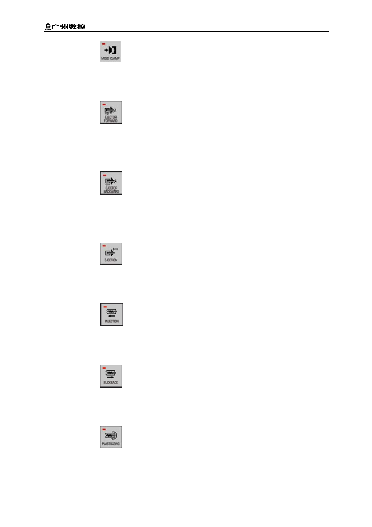
[MOLD CLAMP] button, the indicator is turned on after controlling this
button in the [MANUAL] or [MOLD ADJUST] working mode; the
mold-clamping is then performed, the indicator is OFF and the
operation is stopped after releasing this button.
[EJECTOR FORWARD] button, the indicator is turned on after
controlling this button in the [MANUAL] working mode, the ejector pin
advance is then performed; the indicator is turned off and the
operation is stopped after releasing this button. It is better to eject
based upon the ejection speed 1.
[EJECTOR FORWARD] button, the indicator is turned on after
controlling this button in the [MANUAL] working mode, the ejector
pin retreat is then performed; the indicator is turned off and the
operation is stopped after releasing this button. It is better to retract
based upon the retreat speed 1.
[EJECTION] button, the indicator is turned on after controlling this
button in the [MANUAL] working mode, the multi-ejection series
operation is then performed with thimble; the indicator is turned off
and the operation is stopped after releasing this button.
[INJECTION] button, the indicator is turned on after controlling this
button in the [MANUAL] working mode, the injection is then
performed; this indicator is turned off and the injection is stopped
after releasing this button.
[SUCKBACK] button, the indicator is turned on after controlling this
button in the [MANUAL] working mode, the suck back is then
performed; this indicator is turned off and the suck back is stopped
after releasing this button.
[PLASTICIZING] button, the indicator is turned on after controlling
this button in the [MANUAL] working mode, the plasticizing is then
performed; this indicator is turned off and the plasticizing is stopped
after releasing this button.
8
Page 17
GSK6000 All-Electric Injection Molding Machine Digit Control System User Manual
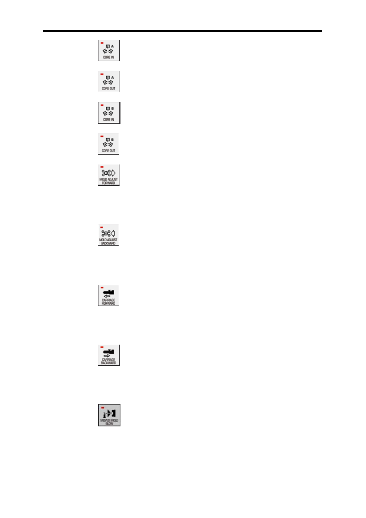
[CORE IN A] button, it can not be used now.
[CORE OUT A] button, it can not be used now.
[CORE IN B] button, it can not be used now.
[CORE OUT B] button, it can not be used now.
[MOLD ADJUST FORWARD] button, the indicator is turned on after
controlling this button in the [MOLD ADJUST] working mode, the
mould-adjustment forward is then performed; the indicator is turned
off and the operation is stopped after releasing this button.
[MOLD ADJUST BACKWARD] button, the indicator is turned on after
controlling this button in the [MOLD ADJUST] working mode, the
mould-adjustment backward is then performed; the indicator is
turned off and the operation is stopped after releasing this button.
[CARRIAGE FORWARD] button, the indicator is turned on after
pressing this button in the [MANUAL] working mode, the carriage
forward is then performed, the indicator is turned off and the
operation is stopped after releasing this button.
[CARRIAGE BACKWARD] button, the indicator is turned on after
controlling this button in the [MANUAL] working mode, the carriage
backward is then performed; the indicator is turned off and the
operation is stopped after releasing this button.
[MOVED MOLD BLOW] button, in the [MANUAL] working mode, the
indicator is turned on after pressing this button in the safety close
process, the moveable plate blowing is then performed; the indicator
is turned off and the operation is stopped after releasing this button.
9
Page 18
GSK6000 All-Electric Injection Molding Machine Digit Control System
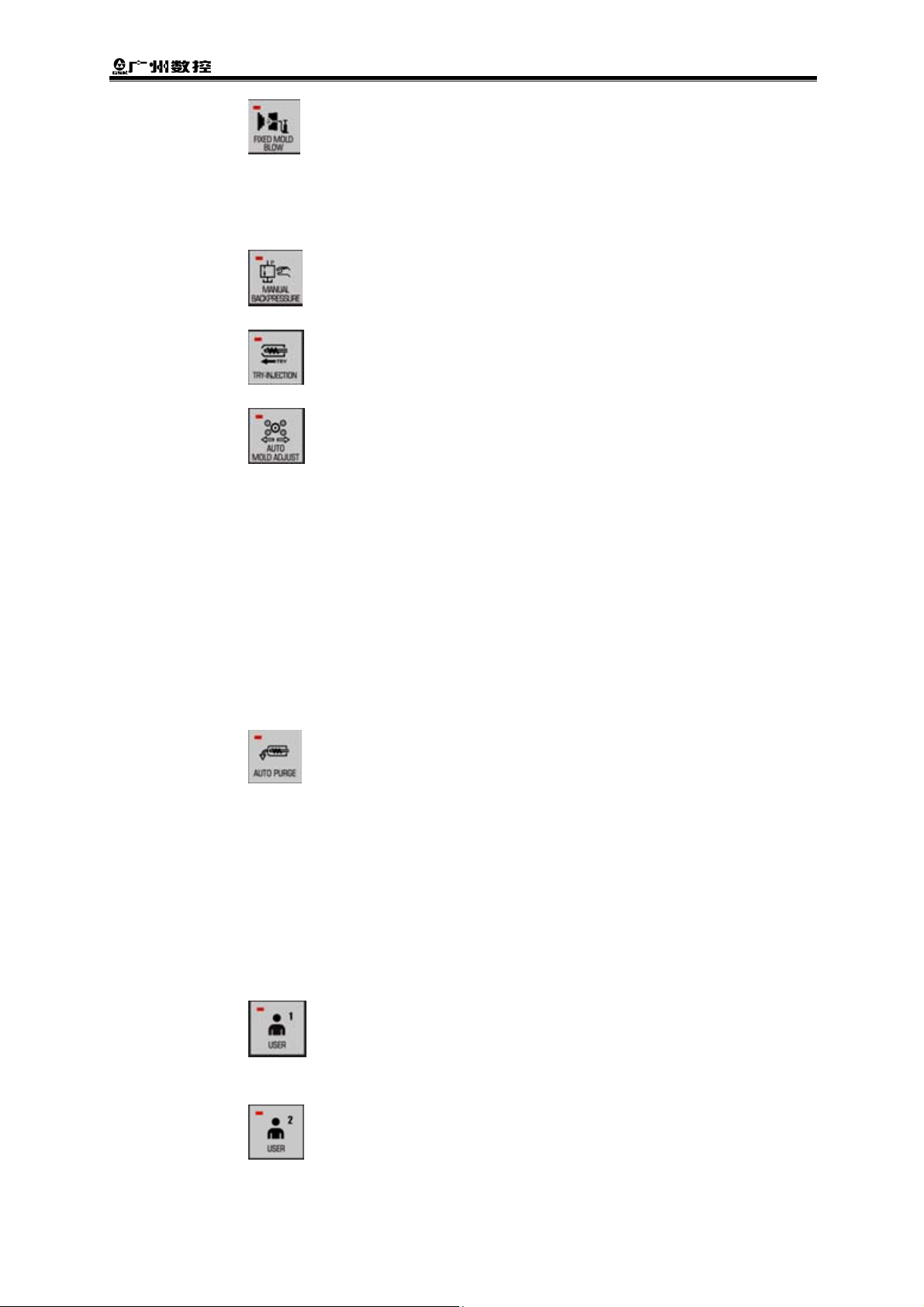
[FIXED MOLD BLOW] button, in the [MANUAL] working mode, the
indicator is turned on after pressing this button in the safety close
process, the stationary plate blowing is then performed; the indicator
is turned off and the operation is stopped after releasing this button.
[MANUAL BACKPRESSURE] button, it can not be used now.
[TRY-INJECTION] button, it can not be used now.
[AUTO MOLD ADJUST] button, the indicator is normally on after
pressing this button in the [MOLD ADJUST] working mode; the
indicator is normally on after controlling the [START] button again,
the automatic mould-adjustment is then performed. The [AUTO
MOLD ADJUST] is performed the automatic mould-adjustment
function based upon the parameter setting based upon the “
HighPre.”
(the desired clamping force, for example: 80T×50%=40T) in the
[Clamp] screen and the one inside the “InstallMold”. Other working
modes can be switched when the indicator of the “START” button is
OFF after the mould-adjustment operation is performed. If you want
to stop this operation in the halfway, press the “STOP” button.
[AUTO PURGE], in the [MANUAL] working mode, the indicator is
normally on after controlling this button when the carriage backward
is reached to the limitation. The automatic purge/discharging function
is performed based upon the setting parameter inside the “Purge” in
the [Mete.Detail] screen. The indicator is automatically turned off and
the operation is stopped after this process is executed. The indicator
is turned off and the current purge/discharging is stopped if this
button is pressed again when the automatic purge/discharging is
being performed.
[USER 1] button, it is reserved for the user, which is used for the
customized button 1 of the function extension.
[USER 2] button, it is reserved for the user, which is used for the
customized button 2 of the function extension.
10
Page 19
GSK6000 All-Electric Injection Molding Machine Digit Control System User Manual
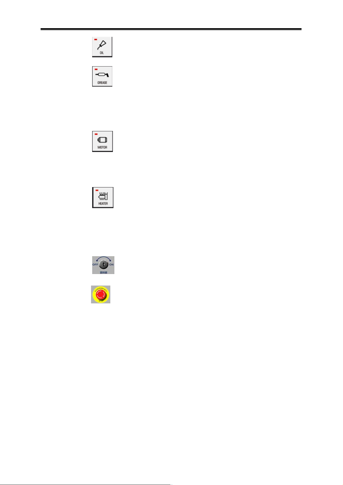
[OIL] button, it can not be used now.
[GREASE] button, firstly, shift to the [Product] screen, switch the
“Open” button following the “GreaseAutoFre.” into the “Close”, then
press the [GREASE] button again; the indicator is normally on and
the automatic filling grease is then performed; the indicator is turned
off and the operation is stopped after the filling is completed.
[MOTOR] button, the indicator is normally on after pressing this
button. All of the motors’ power inside the equipment is turned on;
the indicator is turned off when this button is controlled again, and all
motors’ power is cut off.
[HEATER] button, the indicator is normally on after pressing this
button, the electric heating part then starts its heating function. The
indicator is turned off and the heating is stopped after controlling this
button again.
[Data lock], it can not be used now.
[ESP] button, it is only used for stopping the equipment in the
emergency case. The power both the motor and electric heating of
the system is cut off after pressing this button. After the emergency
stop occurs, the [ESP] button can be controlled after the danger has
been eliminated, and the indicator direction rotates releasing the
emergency stop. (Do not use the common stop).
11
Page 20

GSK6000 All-Electric Injection Molding Machine Digit Control System
CHAPTER THREE SAFETY APPLICATION
In order to enhance the stability of the integral machine, and avoid the hazard accident, it is
important to read this User Manual and comprehend its content before installing and using this
system. Abide by the installation described in the User Manual and the using safety
specifications.
3.1 Safety Using
3.1.1 The Definition of the User
The technician of the system
In this manual, the person who is performing the system maintenance is defined as [System
maintenance technician]. That he who is trained with this system maintenance and acquainted
with this installation system and operation, as well should gain the operation authorities from our
company.
[System maintenance technician] should abide by the following precautions:
(1) It is better to inform the related operator that the operation can not be
performed when the maintenance and detection are operated until mark a
signboard “Do not operate it, system is being maintaining”;
(2) Confirm the ESP of the system and other safety switches can be correctly
operated before performing;
(3) Do not pull out and insert each control cable related with system during
operating;
(4) It is better to protect the multimeter probe (test pen) when metering with
power, prevent against the short-circuit happens during metering;
(5) Ensure the related motor and the mechanism position is within the safety
range when the movement parts are operated.
(6) The operation exceeded the system safety range should be firstly consulted
the maintainer during the operation.
(7) Detect and confirm whether the related cable is connected reliably and
correctly after the system maintenance is finished, as well the overall
disassembly components have been installed correctly.
(8) When the maintenance detection is performed and returns to the normal
operation state, confirm whether the equipment and miscellaneous device
holds in the original state, and if it is in the usable state, notice the whole
relative operators.
Equipment Operator
In this user manual, the high level maintenance professional during operating is defined as
[Equipment operator].
[Equipment operator], is the equipment operators of the GSK, or trained and gained the
12
Page 21

GSK6000 All-Electric Injection Molding Machine Digit Control System User Manual
qualification from the GSK, can perform the following operations.
(1) The system installation uses the technical instruction;
(2) The elimination of the system malfunction.
The repair of the equipment (the exchange of the unit and the replacement of the setting and
the adjusted electrical elements), the [Equipment operator] should comply with the
above-mentioned “Precautions during working maintenance”, as the maintenance professional. It
is very necessary to notice the accidents because the carelessness caused by the skillful for the
equipment operators.
3.2 The Precautions of the Safety Use
This system is fully considered for the security when designing. It is necessary to read and
sufficiently comprehend this User Manual before installing and using, and ensure that the system
can be reliably operated after installing.
3.2.1 The Precaution of the System Installation
Danger
z The ESP is the upmost level safety precaution when the
abnormity occurs. It is important to confirm this signal is
connected and used normally before using the system.
Otherwise, an unexpected result may occur.
z
3.2.2 The Precaution of Guard Against the Electric Shock Hazard
z The power connection of the injection molding machine and
accessory equipments should be installed the breaker, which
should be operated with grounding.
z The insulation resistance (Check whether the electric heater is
normal) should be measured once a year at least.
z The equipment can not be operated when the electrical control
cabinet is opening, because the cabinet should be disassembled
when the maintenance or detection is performed. So, it is
necessary to cut the main breaker and then operate until the
electrolytic capacitor is discharged (discharge 10s).
z The equipment innovation and modification can not be
performed without the permission from the manufacturer.
13
Page 22

GSK6000 All-Electric Injection Molding Machine Digit Control System
The precaution of guard against the electric shock hazard
The facility of the leakage breaker
The product delivered to your esteem company is not installed the
safety equipment such as the leakage breaker.
The national standard of the breaker:
GB 10963-1989| Domestic and similar purpose breaker
GB 14048.2-1994| Low-pressure switch equipment and controllable
equipment, Low-pressure breaker
GB 16916.1-1997| The remaining current motion breaker (RCCB)
without OCP (over-current protection) for domestic and similar
purpose - The Part 1: General regulation
GB 16916.21-1997| The remaining current motion breaker (RCCB)
without OCP (over-current protection) for domestic and similar
purpose – Part 2.1: General regulation is regardless of the RCCB
applicability of the motion function and circuit voltage
GB 16916.22-1997| The remaining current motion breaker (RCCB)
without OCP (over-current protection) for domestic and similar
purpose – Part 2.2: General regulation is related with the RCCB
applicability of the motion function and circuit voltage
GB 16917.1-1997| The remaining current motion breaker (RCBO)
with OCP (over-current protection) for domestic and similar purpose
– Part 1: General regulation
GB 16917.21-1997| The remaining current motion breaker (RCBO)
with OCP (over-current protection) for domestic and similar purpose
– Part 2.1: General regulation is regardless of the RCBO applicability
of the motion function and circuit voltage
GB 16917.22-1997| The remaining current motion breaker (RCBO)
with OCP (over-current protection) for domestic and similar purpose
– Part 2.2: General regulation is related with the RCBO applicability
of the motion function and circuit voltage
GB 1984-1989| AC high pressure breaker
GB 4876-1985| The charge current on-off experiment of the circuit of
the AC high pressure breaker
GB 7675-1987| The on-off capacity group experiment of the AC high
pressure breaker
Supply the AC electric power equipment to the injection molding
machine and others around it, it is recommended that this equipment
should be installed based on the safety countermeasure when the
abovementioned equipments are not set.
The slight high-frequency noise may occur when the inverter is
operating, because the different kind of the leakage breaker, the
current may leak due to the high frequency, and then the malfunction
occurs.
14
Page 23

GSK6000 All-Electric Injection Molding Machine Digit Control System User Manual
System grounding
The power circuit filter is installed inside the control system, and
therefore, the slight leakage current will go through the shell of the
system; the electric shock hazard may occur if the unreliable
grounding is performed. So, never attempt to install and use system
without grounding.
The grounding equipment of the machine
Connect the grounding terminal of the mechanical power and the
factory power, so that the earthing can be performed mechanically.
As for the wiring’s resistance, it is below 100Ω when the power
voltage is below 300V; and it is below 10Ω when the voltage is below
300V.
Inspection of the insulation resistance
The inspection should be performed once yearly, for example,
among the cables, cables other than the grounding, and the
insulation resistance between the grounds. The voltage among the
wires is below 300V, and the insulation resistance is more than
0.2MΩ; if the voltage is more than 300V, and its insulation resistance
is above 0.4MΩ. It is necessary to check the insulation resistance at
least once yearly, such as the motor, electric heater and other
insulation states of the machines. When the insulation resistance is
examinated, do not offer the high voltage of the insulation resistance
megameter in the CMOS circuit, servo motor controllable connector
and the adjacent switches. The connection cable is cut off with the
servo motor’s terminal or the connector. Determinate the insulation
resistance of the servo motor without the connection state, so that
the internal circuit may be damaged.
3.3 The Main Proceeding of the Circuit
3.3.1 The Controllable Circuit
The large amount of digit and analog integral component are used inside the injection
molding machine controller, which are produced with the advanced electronic technique and
possessed of the high reliability and durability and guaranteed the high performance and
accuracy of the control system.
15
Page 24
GSK6000 All-Electric Injection Molding Machine Digit Control System
3.3.2 The Precaution of the Circuit Board
The neutral part of this injection molding machine has several circuit boards inside the
cabinet. The parts installed into these boards are used the most advanced electronic technique
integrated circuit. In these integrated circuits, some IC contains of more than 10000 circuits, so
the circuits are very compact, and greatly improves the reliability and extends its life span.
High pressure (such as the AC220V, AC380V) may occur during the system use equipment,
if the pressure is applied to the control circuit board; it may be damaged the system, so it is
important to pay attention to it when operating.
As for the circuit board, abide by the following items
(1) When the circuit is pull out, inserted, assembled or disassembled, the
controllable power should be cut off, and then it can be performed after
waiting for 10 seconds (the discharge time of the capacitor charging)
(2) Link the fixed card of the cable connector. The malfunction may occur due to
he poor connection.
(3) When the welding or cutting (gas welding or electric welding) is performed
nearby the control cabinet, close the door of the control cabinet.
Environment setting
In order to protect the control equipment, it is necessary to avoid the following
environments for the use conditions of the injection molding machine.
(1) The ambient temperature around the injection molding machine is more than
the range of 0~40 .℃
(2) The place where the ambient humidity is more than 85%RH and the one the
condensing is generated because the change of the rapid temperature.
(3) The place where is with the sunshine directly.
(4) The place of the strong electric field and high magnetic field.
z The variation of the power voltage holds at the range of the ±10%.
(It can not be exceeded at one moment.)
z The variation of the power frequency holds at the range of the
±1Hz.
z The injection molding machine can be stopped after the time of
the simultaneous power-off is cut off one week.
z When it is used in the place where multiple simultaneous
power-off, the
continuous power equipment should be installed
based upon requires.
16
Page 25

GSK6000 All-Electric Injection Molding Machine Digit Control System User Manual
3.4 The Requirement Proceedings of the Installation Auxiliary
Functions
Because the electric flash is easily affected, so pay attention to the following items when
installing the auxiliary equipments.
3.4.1 The Grounding of the Auxiliary Equipments
The cables of the equipments, such as the unloading machine, hopper dryer and mold
temperature adjustor etc are concentrated on the main grounding terminator of the injection
molding machine. Thus, the injection molding machine and all the peripheral machines are
treated as the equal potential, it is added the safety and reduced the noise wave.
The reserved socket of the injection molding machine is a system based upon the
above-mentioned grounding cables, which is connected with the grounding terminal of the
injection molding machine, so if you use this socket, the grounding of the peripheral machines
will be easier.
3.4.2 The Grounding for the Noise Wave
It is recommended that separate the power of the injection molding machine and the other
machines (discharge processing machining, arc welding machine, commutator motor, and the
total number changeable equipment of the silicon controlled etc.) generated the noise wave, the
grounding system of the injection molding machine can not be shared a same place with the
abovementioned machines which may generate the noise wave. The grounding of the injection
molding machine should be performed separately, which can be stably operated without any
noise wave.
3.4.3 Precautions for the Static Noise Wave
The transportation equipments (specially, deliver the plastic inside its plastic tube by the air)
such as the plastic and molding product may generate an intense static noise wave. So, the
grounding joint of the equipment is practically performed.
The material transportation tube should be used the shortest limit length, and depart from
the controller and the screw position detection encoder as much as possible when the channel is
set. The molding product taken from the molds which do not pile nearby the operation panel,
because the strong static may cause the malfunction of the equipment, so it is necessary to
avoid it.
17
Page 26

GSK6000 All-Electric Injection Molding Machine Digit Control System
3.4.4 The Shield of the Electromagnetic Field Equipment
When the injection molding machine grounding connection is performed nearby the
equipment of the strong electromagnetic field, namely, the arc welding machine, discharging
processing machine, and the high frequency heater, the equipment with the noise wave should
be covered by the grounding metal shielding board.
3.4.5 The Use of the Internal DC Power
The AC power such as the DC24V, DC12V and DC5V inside the injection molding machine is
specially used for its internal system, not for the power of the external equipment. Do not use this
power on other purpose other than it is indicated in the User Manual. If you use it freely, it may
cause the low voltage or the noise wave may issue, and the malfunction or other stoppage of this
injection molding machine may generate.
3.4.6 The Usage of the Thermocouple
The thermocouple used in the injection molding machine and a microscale voltage value
may output based upon the temperature at the top of the temperature measure. This value is
formed a digital signal by the signal amplification and A/D conversion, so the voltage that gives
to the thermocouple circuit can not excessive, otherwise, the thermocouple amplification may be
damaged, and therefore, pay attention to the following proceedings when using.
(1) Pay attention to the leakage of the electric heater, which should be changed it
as for the one with poor insulation. Specially, the mold may be leaked using
the mini electric heater, so check the insulation resistance periodically.
(2) When the thermocouple top connected with the circuit should be disassembled
from the mold and heater hopper, do not put the static on the metal part of the
thermocouple. In this case, it is recommended that the top of the thermocouple
is temporarily connected with the metal parts such as the frame of the injection
molding machine.
18
Page 27
GSK6000 All-Electric Injection Molding Machine Digit Control System User Manual
CHAPTER FOUR OPERATION
4.1 The Brief of the Operation
Mainly, this chapter is introduced the corresponding functions of the operation system in
each stage of the injection molding machine.
4.1.1 System Working Mode
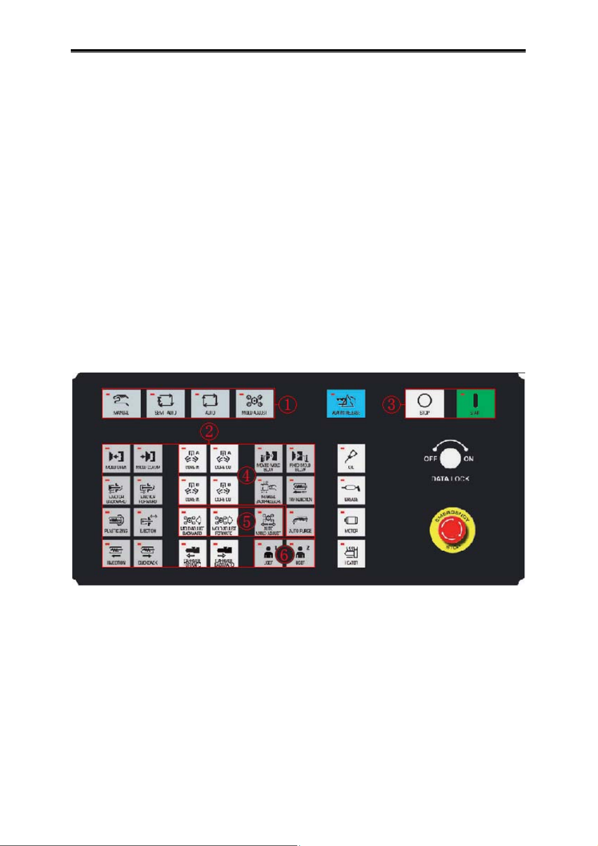
The system has four kinds of working modes: [MANUAL] mode; [SEMI-AUTO] mode;
[AUTO] mode and [MOLD ADJUST] mode. The working modes (For example, the figure ①) can
be shifted by the buttons on the miscellaneous panel, which can not be operated simultaneously.
Different working modes can be chosen based upon your circumstance, and the four modes will
be introduced below.
The button classification figure of the auxiliary operator panel
① The button area of the working mode selection;
② The same operation button area both the [MANUAL] and [MOLD ADJUST]modes;
③ The [START], [STOP] button of the operation of the system [SEMI-AUTO] or [AUTO]
or [MOLD ADJUST];
④ Specially for [MANUAL] mode operation button area;
⑤ Specially for [MOLD ADJUST] mode operation button area;
⑥ The button area of the user selection (fail to offer);
19
Page 28
GSK6000 All-Electric Injection Molding Machine Digit Control System
z When the system is turned on, the manual mode is started by default.
z The operation of each mode, refer to the switch conditions among the modes and
the system response after shifting in the Section 4.2.2 in this manual.
4.1.1.1 [MANUAL] Mode Explanation
[MANUAL] Mode is mainly used for the system debugging at the first time and the
operation for a certain movement after the produce dwells. It is necessary to enter the
Manual mode when the ②④ areas buttons on the auxiliary operator panel should be
performed by manual. Refer to the Section 4.2.2.2 (Manual Operation Mode) for the
button explanations. The system will be controlled this operation by which the parameter
is set by this operation when the button of a certain movement is pressed, till it is
automatically stopped after the completion of the operation.
z The operation will be stopped too when releasing the button before the controllable
operation does not completed.
z The system may be performed different treatments to the same operation with the
[MOLD ADJUST] mode. Refer to the “[MOLD ADJUST] mode explanation” for details.
4.1.1.2 [SEMI-AUTO] Mode Explanation
The system is automatically controlled the injection molding machine based upon the
injection molding flow to complete a molding period from the clamping to the ejector, and
then the machine is stopped. Refer to the Section 4.2.2.3 [SEMI-AUTO] Mode Operation
in this User Manual for details. The purpose of the [SEMI-AUTO] mode is that the
trial-production can be performed based upon the [SEMI-AUTO] mode before entering
the [AUTO] batch-production mode. Judge whether the parameter is adjusted checking
the productive quality, so that the batch-production can be performed.
The flow of the injection molding machine is shown below:
20
Page 29
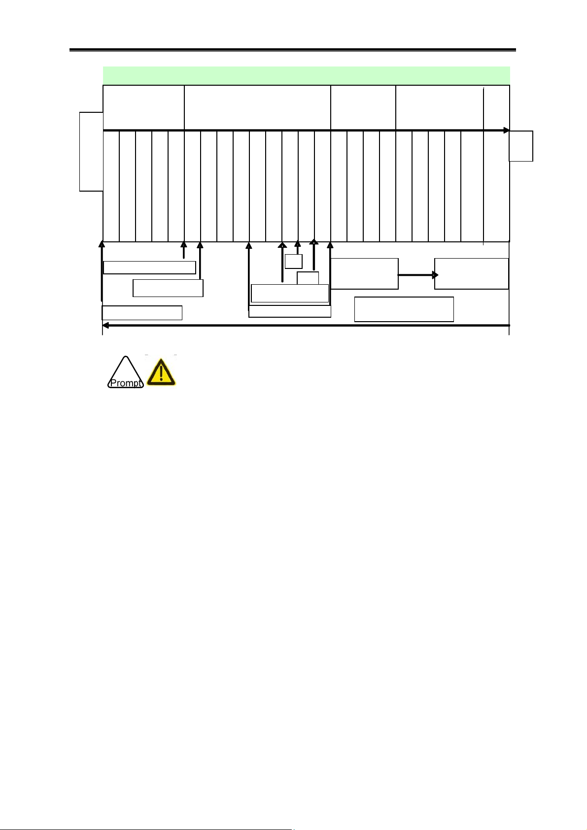
GSK6000 All-Electric Injection Molding Machine Digit Control System User Manual
g
g
j
y
Injection
g
Carriage retreat
A
g
Mold-clamping
utomatic start
Intermediate speed
High speed
Low voltage and speed
High speed
Safety door close
Mold-clamping completion
Nozzle contract
Mold-opening stop
Hi
Carriage
h volta
e
Period time
Injection metering
In
ection dela
Metering delay
Screw retreat
Packin
Depressure before
meterin
Cooling time
Screw retreat
Metering
SM
SD
Mold-opening
High speed 2
High speed 1
Low speed
Slow speed
Blowing start
time
Restart pressing the
automatic start
Ejection
Ejector advance
Ejector delay
Ejection dwell
Ejector retreat
Blowing
operation time
ejector plate retreat
Confirmation of mold
ate time
Intermedi
End
z If you want to start the [SEMI-AUTO] or [AUTO] operation, the following contents
should be applied:
(1) Mold-opening in-position, ejector backward in-position, screw backward in-position
(metering plasticizing in-position);
(2) Motor’s power ON, electric heat power is ON and its temperature reaches the setting
value;
(3) Motor is on the static state
(4) Safety door closes;
The system alarm may occur pressing the [START] key if the above-mentioned
contents are not applied.
z The in-position check of the three signals belonging (1) can be viewed by the “I/O
diagnosis” page (Refer to the Section 4.5.1 I/O diagnosis for details); if it does not,
adjust it to the in-position mode by the [MANUAL].
4.1.1.3 [AUTO]] Mode Explanation
The injection molding machine can be mass-produced after the system enters the
[AUTO] mode, which is same as the [SEMI-AUTO] mode; the system does not stop
instead of beginning a new period after a molding period is completed, till the production
plan is finished. Refer to the Section 4.2.2.4
4.1.1.4 [MOLD ADJUST] Mode Explanation
[AUTO] mode operation for the details.
21
Page 30
GSK6000 All-Electric Injection Molding Machine Digit Control System
It is necessary to enter this mode if the mould-adjustment is needed to be performed.
The buttons on the miscellaneous panel can be operated, namely, the , in the ②⑤
following figure, refer to the Section 4.2.2.5 [MOLD ADJUST] mode operation for details.
Mould-adjustment (molding thickness adjustment) is adjusted the mold-clamping
mechanism position based upon the thickness of the mold; so that its elbow can be
entirely extended reaching the top clamping force. It can be performed with the Manual
or Automatic mode, usually, select the automatic mold thickness to adjust it. The [AUTO
MOLD ADJUST] operation should be performed when the following cases are
generated:
(1) After the mold is installed;
(2) Change the setting value of the mold thickness or “ClampPre.”;
(3) After the mould-adjustment is performed by manual;
(4) The mold heating can be performed after its stable temperature lasts for a period
time.
z The operation is performed in the [MOLD ADJUST] mode; the system controls the
motor’s operation based upon the parameter setting of the “InstallMold” on the page
of the “Clamp”, which is shown as the following figure . It ① is different with the
operation of the [MANUAL] mode.
22
Page 31

GSK6000 All-Electric Injection Molding Machine Digit Control System User Manual
4.1.2 The Confirmation Before Injection
The following items should be detected before operating this machine.
4.1.2.1 Start or Stop the Motor
(1) Start the motor
The indicator on the button is ON after the button on the miscellaneous panel is
controlled.
(2) Stop the motor
The indicator on the button is OFF after the
button is controlled.
23
Page 32

GSK6000 All-Electric Injection Molding Machine Digit Control System
4.1.2.2 Mold Clamping and Mold Opening
(1) The operation of the mold clamping
Close the safety door → Enter the manual mode → Press ①② ③
the mold-clamping operation
z Do not perform the interrupted mold-clamping operation when the high speed
clamping is performed. It is better to set the clamping speed at the low one if the
interrupted operation will be performed.
(2) Mold-opening operation
Close the safety door → Enter the manual mode → Press the ①② ②
the open-molding operation
4.1.2.3 Ejector Operation
① Close the safety door → ② Confirm the clamping plate at the mold-opening position
→ Start ④
→ Start ④
→ Set the “Ej.Open” after entering the “Ejection” page → Press the ③④
or → Start the ejector operation.⑤
The speed and position parameter of the ejector are determined by the “Ejection” page.
z The ejector would not be operated if the mold does not reach to the mold-opening
stop position;
z It is necessary to stop the safety door;
z When the ejector is adjusted, the ejector stroke is regulated as short as possible at
the beginning for guard against the damage of the mold; and then improve the
stroke step by step till to the desired ejector one.
z When the ejector is operated, it is better not take out the product from the mold’s top
or bottom by your hand to prevent accident.
or
24
Page 33

GSK6000 All-Electric Injection Molding Machine Digit Control System User Manual
4.1.2.4 The Operation of the Ejection Equipment
Press the key, the ejection equipment forwards to the mold; press key,
the ejection equipments backwards. If the move is reverse, replace any of two phases’
power of the carriage motor. Stop the move when touching the limit switch. Note: firstly
use the “MOLD ADJUST” mode, after the power is turned on at the first time; confirm that
the directions between the mould-adjustment forward and mold-clamping are normal,
and then ensure the carriage forward direction.
4.1.2.5 Mold Installation
(1) Ensure the used installation specification of the machine; refer to the “MachinePara.”
in the
[Clamp] page;
(2) Mold installation; refer to the Section 4.3.1.1.1 Mold Installation for details;
(3) Adjust the position of the ejector pin and its quantity to fit the mold;
(4) Adjust the automatic mold thickness;
4.1.2.6 Screw Operation
The movement modes of the screw are vary from the operations, for example, injection,
suck back, plasticizing, purge/discharging and screw operation, and refer to the following
items:
(1) [INJECTION]
The screw directly forwards with a constant speed when the injection is operated.
In the [MANUAL] mode, press
set by Pv1 of the “Inj.Pre.” and the speed set by “V1” of the “FillSpe.”, and then it is
stopped after reaching to the position value set by the “V-PSwitch”.
When the [SEMI-AUTO] and [AUTO] operations are performed, the screw will be
operated injecting the related parameter based on the “Metering”. Refer to the Section
4.3.3.1 Injection Metering for details.
(2) [SUCKBACK] (the screw retreats)
key, the screw moves based upon the pressure
In the [MANUAL] mode, press the
position according to the speed value set from the “deceleration speed”.
[SEMI-AUTO] and [AUTO] are automatically performed the suck back. Refer to the
Section 4.3.3.1 Injection Metering for details.
(3) ([PLASTICIZING] metering)
key, the screw retreats to the “SD” setting
25
Page 34

GSK6000 All-Electric Injection Molding Machine Digit Control System
When the metering is performed, the plasticizing retreats along with the rotation of the
screw.
In the [MANUAL] mode, press the
key, the screw will be rotated with the “VS”
setting speed, it retreats to the “SM” setting position after overcoming the “PB”
backpressure setting. Note: The plastic may flow out when the backpressure is higher, to
prevent the plastic from flowing, it is better to operate it by the suck back and
plasticizaing each other.
When the [SEMI-AUTO] and [AUTO] are operated, the screw is metered to the “VSLL”
setting position at the “VS” rotation speed, then meter to the “SM” position at the “VSL”
rotation speed, and then retreat to the “SD” position at the “Dec.Spe.” after completing
the plasticizing (the screw stops rotation).
Refer to the Section 4.3.3.1 Injection Metering for the related parameters.
(4) [AUTO PURGE]
The material-cleaning is composed of three operations: Injection, Front screw back and
metering.
The “ForwardScrewBack” is that the screw retreats to a certain distance to reduce the
pressure after the injection packing is performed.
As for the purge/discharging operation, refer to the Section 4.3.3.2.3 purge/discharging
for details.
z In order to guard against the screw, firstly, check the protection precautions of the
screw before operating it. Refer to the Section 4.3.3.2.3 Purge/discharging
4.1.2.7 Temperature Control
(1) Heater (Heating cylinder) temperature
Set the appropriate heating temperature to warm up based upon the selected material.
(2) Mold temperature
The temperature should be set if the mold heating should be performed; the insulating
board should be installed when the molding temperature is higher.
Refer to the Section 4.3.2.2 Heating for the temperature setting.
(3) The molding temperature of the plastic and the mold temperature table is shown
below (This is for your reference only, it is better to consult the material manufacturer for
the upmost reasonable molding temperature).
26
Page 35

GSK6000 All-Electric Injection Molding Machine Digit Control System User Manual
Plastic name English Molding
temperature ℃
Polystyrene/Stryron PS 180~260 30~50
HIPS (High Impact
Polystyrene)
Polypropylene –
Butadiene - Styrol
Low Density
Polyethylene
High Density
Polyethylene
Polypropylene PP 180~270 30~60
Soft Polrvinyl
Chloride
Hard Polrvinyl
Chloride
Polymethyl
Methacrylate
Polyformaldehyde POM 190~210 40~80
Makrolon PC 280~320 80~100
HI-PS 170~260 30~50
ABS 190~260 40~70
LDPE 160~260 30
HDPE 260~300 30~50
PVC 150~180 20~50
PVC 180~200 30~60
PMMA 210~240 50~70
Mold temperature
℃
Polyamide 6 PA 6 240~260 80~110
Polyamide66 PA 66 260~290 80~110
Polyamide 610 PA 610 60~90
Polyethylene
Terephthalate
Polyethylene
Terephthalate
Polyphenylene
Sulfide
PET 280 60~120
PBT 250~270 80~110
PPS 300~330 90~130
4.1.3 Plan Injection Function
The system is offered the automatic start heating function after the power is turned on.
4.1.3.1 Automatically start the electrical heating
Enter the “AutoStart” page clicking the button from the “Heater” page.
27
Page 36

GSK6000 All-Electric Injection Molding Machine Digit Control System
4.1.3.2 Automatically Start the Electrical Heating Setting Method
Step one: Calibrate the display data and time on the screen and its working data and
time is normal.
Step two: Set the “Close” of the automatic start heater, and then shift it as “Start”.
Step three: Set the week and time, for example, Monday, touch “Mon”, if the color is thin,
which means that it is selected.
Step four: Select the heating method. For example: the current heating method is
“Holding temperature”, the shift selection can be performed after touching it.
Step five: Start the automatic start.
Step six: Confirm the “HEATER” indicator is normally ON on the miscellaneous panel,
and then complete the automatic start setting. Note: If the “HEATER” indicator is OFF,
the automatic heating function can not be started. In order to the safety, it is better to
install an automatic open on the water-supply equipment.
28
Page 37

GSK6000 All-Electric Injection Molding Machine Digit Control System User Manual
4.1.4 Injection Condition Setting
4.1.4.1 Read Parameter
z The system offers the injection parameter function for saving the current setting. The
saved parameter can be read that you can use the saved one as the current
parameter. Refer to the Section 4.4.4.2 for details.
The parameter range saved by the system is mold clamping/opening parameter, injection
metering parameter, ejector parameter, temperature parameter, but the administration
parameter does not include. It can be set again by the production status.
It is better to save the current parameter before extracting the existing parameter.
If the extracted parameter is the one which is the acceptable product for the previous
production; the qualified product can not be consecutively performed after using it again; it is
better to trial product at the first time.
4.1.4.2 Mold Opening/Clamping Parameter
4.1.4.2.1 Mold Opening/Clamping Page
29
Page 38

GSK6000 All-Electric Injection Molding Machine Digit Control System
: Mold① -clamping parameter area.
: Mold② -opening parameter area.
: Mold③ -adjustment parameter area.
: Check the machine specification.④
: Foreign matter detection.⑤
: Display the current mould⑤ -adjustment position and mold position.
: Page shift key.⑦
The mold opening/clamping can be manually operated after finishing the
above-mentioned and .①② ⑤
The mould③ -parameter is the movement parameter of the mold clamping/opening when
the [MOLD ADJUST] or [AUTO MOLD ADJUST] is performed.
The mechanical parameter specification of the machine can be checked after entering
.④
Refer to the Section 4.3.1.1 Mold Opening/Clamping Page for details.
30
Page 39

GSK6000 All-Electric Injection Molding Machine Digit Control System User Manual
4.1.4.2.2 The Detailed Page of the Mold Opening/Clamping
: The parameter section of the molding protection.①
: Blowing pa② rameter section.
: Core③ -pulling parameter area.
: Page shift key.④
Refer to the Section 4.3.1 Mold Opening/Clamping for details.
31
Page 40

GSK6000 All-Electric Injection Molding Machine Digit Control System
4.1.4.3 Injection Metering Parameter
4.1.4.3.1 Injection Metering Page
: Injection metering time parameter area.①
②: Injection filling speed and the screw position parameter area.
: Metering parameter area.③
: V④ -P shift parameter area.
: Injection pressure parameter area.⑤
: Packing parameter area.⑥
: Open the “DataDescription” window.⑦
: Page shift key.⑧
The ejection (injection) operation can be performed in the manual mode after the values
of the ”④ Pos.”, “V1” and “Pv1” are set; the suck back and the plasticizing ②⑤
(metering) operation can be performed after item is performed.③
An integral injection metering operation can be formed after all parameters on the page
are set.
Refer to the Section 4.3.3.1 Injection Metering for details.
32
Page 41

GSK6000 All-Electric Injection Molding Machine Digit Control System User Manual
4.1.4.3.2 Metering Detail Page
: Injection the Max. acceleration/deceleration and the compression/depression time ①
parameter area.
: Nozzle retreat and the metering function set. [ParalMete.Operate] operation does not ②
use now.
: Injection metering miscellaneous parameter area.③
: Purge/discharging parameter area.④
: Pressure detection treatment. Do not use temporarily⑤
: Page shift⑥ key.
The parameters in the areas are mainly controlled to the injection metering ①②③
operation when it is performed in the semi-automatic or full-automatic.
is the purge/discharging detail parameter setting.④
Refer to the Section 4.3.3.2 Injection Metering for details.
33
Page 42

GSK6000 All-Electric Injection Molding Machine Digit Control System
4.1.4.4 Ejector Parameter
: Set the start/close times of the ejector.①
: Ejector mode and the movement parameter area.②
: Ejector time setting area.③
: The ejection function during mold④ -opening, it does not use now.
: Display the pos⑤ ition of the ejector.
: Page shift key.⑥
Note: the “Ej.Open” in the must be opened, so that the ejector can be performed.①
is the ejector movement method when it is automatically performed.②
When the different ejector modes in the are selected, the dif② ferent parameters may be
generated on the screen. It is better to set it according to the mold ejection requirement
when automatic operation is performed. The first ejector speed and pressure value
should be set in the different modes, when the manual operation is performed.
Refer to the Section 4.3.1.3 Ejector for details.
34
Page 43

GSK6000 All-Electric Injection Molding Machine Digit Control System User Manual
4.1.4.5 Temperature Parameter
4.1.4.5.1 Heater Temperature
: The display area of the heating control status.①
: Set the cold② -start prevention time of the screw. Warming-up and the resin detaining
monitoring time does not use temporarily.
: The parameter setting area of the heater temperature ③
: Force the holdin④ g temperature function. The holding is performed in the abnormity
case. Do not use temporarily.
: Page shift key.⑤
Set the “Object” based upon the plastic type.③
Purpose 2 is that the screw may be damaged during operating when the plastic does not
reach the setting temperature.
Refer to the Section 4.3.2.2.2 Heater Page for details.
35
Page 44

GSK6000 All-Electric Injection Molding Machine Digit Control System
4.1.5 Confirm Before the Batch Production
4.1.5.1 Purge/discharging
The purge/discharging operation should be performed in the following cases:
1. If the used plastic is a kind of decomposition resin of which the resin should be
cleaned to guard against remain.
2. The color or the type of the raw material is changed.
3. After the batch production is performed, the heater should be performed the heating
as short as possible before the next molding operation occurs.
Refer to the Section 4.3.3.2.3 Purge/discharging for details.
4.1.5.2 Production Quantity Setting and the Treatment After Producing
①: Set the batch production quantity.
②: Production status.
③: The production state treatment by the system.
④: Detailed information of the Inferior product status.
36
Page 45

GSK6000 All-Electric Injection Molding Machine Digit Control System User Manual
⑤: Record the historical machining times and it can not be changed. Set the automatic
grease-supply
⑥: Clear the production record.
The system alarm may occur after a box of quality products are manufactured when the
“AlarmAf.Package” is started. The production will be continued after the “Delay” is
finished.
Refer to the Section 4.4.2 Production Management for details.
4.1.5.3 Quality Management
①: Display the reference time in the automatic batch production.
②: Quality product judge switch, reference value obtaining setting.
③: M3, do not use temporarily.
④: Quality/inferior production judgment condition.
⑤: The treatment of the inferior production
⑥: Page shift key.
If you want to get the reference value and the related parameter setting, refer to the
Section 4.4.3 Quality Management for details.
37
Page 46

GSK6000 All-Electric Injection Molding Machine Digit Control System
4.1.5.4 Tendency Chart
: Select the displayed items:①
: Display the chart data.②
: Operate the chart data.③
: Page shift ④ key.
Select the 4 data which is to be monitored and its wave displays with the chart. Refer to
the Section 4.4.3.2 Tendency Chart for details.
38
Page 47

GSK6000 All-Electric Injection Molding Machine Digit Control System User Manual
4.1.5.5 Statistics
: Display the previous 8 modules during the system batch production.①
: Operate the s② tatistics table
: Page shift key.③
Note: This page is only displayed the data of the previous 8 modules. The system is only
record the data of the previous 8 modules when the external memory does not
insert. If the external is performed, record all data of the module to it.
39
Page 48

GSK6000 All-Electric Injection Molding Machine Digit Control System
4.2 The Button Operation of the Auxiliary Panel
4.2.1 Preparation/Confirmation Before Operation
4.2.1.1 The Reset Operation of the ESP Button
(1) The alarm prompt occurs on the upper right corner after
pressing the
(2) The reset operation is performed based upon the arrow’s direction of the
alarm prompt is cancelled at the upper right corner after resetting.
z The
which is only use in the emergency case instead of stopping the machine as usually.
button is used for immediately stopping the injection molding machine,
.
4.2.1.2 The Operation of the Main Power ON
Step one: The power for switching on the main power.
Step two: Switch on the controllable system power.
Step three: The default interface appears after the power is turned on.
, the
z GSK6000 digit control system has a page display function after the machine is ON.
The following operations are shown below:
40
Page 49

GSK6000 All-Electric Injection Molding Machine Digit Control System User Manual
Step one: Press the , then shift to the “I/ODiagnosis” interface on
the “Monitor” interface.
Step two: Enter the “StyleSet” interface after pressing
.
41
Page 50

GSK6000 All-Electric Injection Molding Machine Digit Control System
Step three: Control the green frame button at the left of the
setting page after the machine is ON.
z For example: If user hopes the page is “Heater” one after the machine
is ON, the following operations should be performed after entering the
“StyleSet” interface.
Step one: Click the green frame button at the left of the .
, and then select the
Step two: Select the user specified page (for example: the “Heater”
interface).
42
Page 51

GSK6000 All-Electric Injection Molding Machine Digit Control System User Manual
Firstly enter the user specified page after the control system is restarted.
z Press the
(“Monitor” page).
4.2.1.3 Motor’s Power ON
The button indicator is normally ON after pressing button, the motor is then
started.
z The motor’s button is used for switching on the strong current of the servo
driver. The protection circuit should be set because the driver strong
current may be generated the tremendous current impact during switching
on, and therefore, do not frequently ON/OFF to the driver, otherwise, the
normally alarm of the driver may occur. It is recommended that the motor
only can be opened after the power is turned off for 6 seconds.
button to restore the system’s default page
2.1.1.1 The Power ON of the Electric Heater
Step: Shift to the “Heater” interface after pressing button, and the set
the appropriate range to the processing of the raw-material plastic heating.
43
Page 52

GSK6000 All-Electric Injection Molding Machine Digit Control System
Step two: Confirm the heater state, object temperature, upper limit temperature, lower
limit temperature, holding temperature and forced holding temperature.
Step three: Press the button.
Step four: Set the temperature base upon the using plastic character; set the
“ColdStartPreventTm.”.
44
Page 53

GSK6000 All-Electric Injection Molding Machine Digit Control System User Manual
z The “ColdStartPreventTm.” is the screw protection time against damaging
the screw of which the material inside the charging barrel does not
completely melt after preventing the temperature of the charging barrel
reaches.
z Refer to the Section 4.3.2.2.2 Heater Page for details.
4.2.2 The Processing of each Operational mode
4.2.2.1 The Mutual Operation of each Mode
The buttons on the auxiliary panel can be operated regardless of the [MANUAL],
[SEMI-AUTO], [AUTO] and [MOLD ADJUST]:
(1)
button: The indicator is ON after pressing one button, and then the
motor’s power is turned on. The power is turned off after press it again.
z In order to the safety operation, it is better to cut the power of the
motor in the [MANUAL] mode.
45
Page 54

GSK6000 All-Electric Injection Molding Machine Digit Control System
(2) button: The indicator is ON after pressing the button, and then the
electric heater’s power is turned on. Cut off the electric heater’s power after pressing
it again.
z In order to safety operation, it is better to cut off the electric heater’s
power in the [MANUAL] mode.
(3)
button: The corresponding indicator is ON after pressing the button, the
lubrication is then started.
z The grease-supply and automatic grease-supply can be carried out in
GSK6000 control system:
1) Automatic grease-supply. The
grease-supply mode. The automatic grease-supply should be
performed based upon the following steps:
button is disabled in this
Step one: Shift to the “I/ODiagnosis” interface pressing the
in the “Monitor” interface.
46
button
Page 55

GSK6000 All-Electric Injection Molding Machine Digit Control System User Manual
Step two: The password input interface occurs after pressing the
button.
47
Page 56

GSK6000 All-Electric Injection Molding Machine Digit Control System
Step three: Enter the “SystemSet” interface inputting the password.
Step four: Set the data of the “GreaseAutoFre.” frame.
Step three: Press the
“GreaseAutoFre.” input frame, the button displays
button at the right after pressing the
, then the
grease-supply switch is turned on. The automatic grease-supply then performs once
after the control system is machined the module of the “GreaseAutoFre.”
48
Page 57

GSK6000 All-Electric Injection Molding Machine Digit Control System User Manual
2) Manual grease-supply:
Step one: Confirming the button at the right of the “GreaseAutoFre.”
input frame displays
state, the automatic-supply
function is then closed.
Step two: Press the
immediately started.
(4) In the case of emergency, press the button, the power both the electric
heater and the motor is cut off, every operating motor is immediately stopped.
, the grease-supply operation is then
(5) button: the alarm prompt displays at the upper right corner on the
controllable system interface. User can clear the alarm or the alarm prompt based
upon the alarm resource which is displayed with the system after pressing this
button, and then the other operations can be performed.
4.2.2.2 Manual Operation Mode
4.2.2.2.1 Button Operation Explanations both the Operation Mode Shift ([MANUAL] mode)
and the Auxiliary Operation Panel.
Press the
[MANUAL] one, and then the following buttons can be operated.
[MANUAL] button, after the operation mode is set to the
49
Page 58

GSK6000 All-Electric Injection Molding Machine Digit Control System
(1) The button operation of the injection molding equipment
: [CARRIAGE FORWARD] key: the corresponding indicator is ON after
pressing this button, the injection molding equipment forwards, and vice versa.
: [CARRIAGE BACKWARD] key: the corresponding indicator is ON after
pressing this button, the injection molding equipment backwards, and vice versa.
(2) Ejector-pin button operation
[EJECTOR FORWARD] button: the corresponding indicator is ON after
pressing this button, the ejector-pin is then performed, and vice versa. Note: Do not
stop for long time after the ejector-pin is performed, so that the alarm of the ejector
driver protection occurs, it may cause restart the whole machine.
[EJECTOR BACKWARD] button: the corresponding indicator is ON after
pressing this button, the ejector-pin is then retreated, and vice versa.
50
Page 59

GSK6000 All-Electric Injection Molding Machine Digit Control System User Manual
[EJECTION]: The corresponding indicator is ON after pressing this button,
the multi-ejection of the ejector-pin is retreated. The ejection times can be set based
upon the value in the “Ej.Times” input frame on the “Enection” interface. The
corresponding indicator is OFF after releasing this button; the ejector operation is
then stopped.
z The advanced condition of the ejector button operation:
i. The ejector switch should be opened, refer to the following steps:
Step one: Enter the “Clamp” interface after pressing the
button.
51
Page 60

GSK6000 All-Electric Injection Molding Machine Digit Control System
Step two: Enter the “Ejection” interface after pressing the button.
Step three: The button becomes
after pressing the
button. The , and buttons can
be operated, after the ejector operation is started. The ejector times of the
[Ejection] can be input the “Ej.Times” to the frame.
52
Page 61

GSK6000 All-Electric Injection Molding Machine Digit Control System User Manual
The mold-opening should be performed in-position, if it does
not, the upper right corner of the interface may display
the
operation again after pressing the
when ejecting. It is better to perform the ejector
to adjust.
(3) The button operation of the mould opening/clamping:
button: The corresponding indicator is ON after pressing this button, the
moveable plate is performed the mold opening, and vice versa.
button: The corresponding indicator is ON after pressing this button, the
moveable plate is performed the mold clamping, and vice versa.
(4) The operation of the screw button
button: The corresponding indicator is ON after pressing this button, the
screw is then retreated, and vice versa.
button: The corresponding indicator is ON after pressing this button, the
ejection operation is then performed, and vice versa.
button: The corresponding indicator is ON after pressing this button, the
plasticizing operation is then performed, and vice versa.
1. The preconditions before installing the screw:
a) The temperature of the heater should be reached to the
upper/lower limit range of the object temperature, and the
cold-start time arrives.
53
Page 62

GSK6000 All-Electric Injection Molding Machine Digit Control System
Shift to the “Heater” interface after pressing the
button.
User can set the object, upper/lower limit temperature and holding
temperature based on the actual requirement, the electric heater can be started
pressing the
; the “HeaterState” frame display “Heating”. The “Current” on
the interface displays the actual temperature value of the heater.
54
Page 63

GSK6000 All-Electric Injection Molding Machine Digit Control System User Manual
When the current heater temperature reaches to the object one, the “HeaterState”
displays “Over”.
b) Close the “Forced holding temperature” function. The screw can not be
operated after the “Forced holding temperature” function is started. Close
the “Forced holding temperature” function by pressing the
button (the button becomes after
clicking), the screw key then can be controlled.
(5) Button operation of the automatic purge
button: The corresponding indicator is ON, after pressing this button, the
automatic purge is then performed.
z The efficient condition of the : the injection equipment can be
retreated to the case of the block-cleaning pressing the
the automatic purge/discharging then can be performed.
z Refer to the Section 4.3.3.2.3 Purge/discharging for details.
key,
(6) [CORE IN] [CORE OUT] key operation does not use temporarily.
(7) [MANUAL BACKPRESSURE] button does not use temporarily.
[Manual backpressure] button does not use temporarily.
55
Page 64

GSK6000 All-Electric Injection Molding Machine Digit Control System
(8) Mold blowing key operation
button: The indicator is ON in the [MANUAL] working mode after pressing
this button, the movable plate blowing is then performed; the indicator is OFF and
the operation is stopped after releasing.
button: The indicator is ON in the [MANUAL] working mode after pressing
this button, the stationary plate blowing is then performed; the indicator is OFF and
the operation is stopped after releasing.
(9) Trial ejection button operation does not use temporarily.
[TYR EJECTION] button does not use temporarily.
4.2.2.2.2 [MANUAL] Mode Operation Precaution
The mold clamping operation and ejector operation have relationships, which are shown
below:
1) The
the mold-opening position after pressing the
2) The
, and buttons are enabled, as long as the plate retreats to
.
, and buttons are disabled when the mold-opening does not
perform the in-position.
Do not shift to the [Clamp] screen changing the mold-opening stopping position in the state
of the ejection from the ejector pin; otherwise, the ejector pin can be neither retreated nor
clamped/opened. It is better to set the mold opening position to the back of the actual mold
opening position, then the ejector pin retreats, and then change the desired mold-opening
stopping position.
56
Page 65

GSK6000 All-Electric Injection Molding Machine Digit Control System User Manual
4.2.2.3 [SEMI-AUTO] Mode Operation
4.2.2.3.1 The Usable Button Operation of the Operation Mode Shift ([SEMI-AUTO] Mode)
and Auxiliary Operation Panel
Press the button, the following button operation can be performed after
the operation mode is set the [SEMI-AUTO] mode.
(1) [START] , [STOP] button operation
button: The corresponding indicator is ON after pressing this button, the
injection molding machine is automatically performed a cycle operation, then
automatically stop; the indicator is then OFF after stopping.
button: The [SEMI-AUTO] operation is immediately stopped after pressing
this button.
57
Page 66

GSK6000 All-Electric Injection Molding Machine Digit Control System
z Shift to the [AUTO] mode by pressing the [AUTO] button,
during the [SEMI-AUTO] mode, and then it performs according to the
[AUTO] mode, actually, it enters the next working period and does
not stop after performing one cycle operation. The normally stop in
the [AUTO] mode: firstly shift to the [SEMI-AUTO] mode pressing the
button; and then the injection molding machine is
automatically stopped after performing one cycle.
z In the [SEMI-AUTO] operation mode, shift to the [MANUAL] mode
pressing the
is not recommended to shift this operation.
z The [SEMI-AUTO] operation is immediately stopped pressing the
button, in this case, the [MANUAL] button should be
controlled, then shift to the
opening/clamping, ejector pin and metering in-position operations,
and then press the
mode. The next working period is continued pressing the
button.
button, the motor is stopped after shifting. It
mode performing the mold
button, shift return to the [SEMI-AUTO]
z The [MOLD ADJUST] mode can not be shifted during the
[SEMI-AUTO] mode operation.
58
Page 67

GSK6000 All-Electric Injection Molding Machine Digit Control System User Manual
4.2.2.3.2 The Operation Schedule of the [SEMI-AUTO] Mode
①
②
③
④
Cooling time
Beginning
condition
Mold -clam p in g
Forward seat
Injection delay
Inje ction
Packing
Metering delay
Metering
Rear screw back
Backward seat
delay
Front screw back
Backward seat
⑤
⑥
Mold-opening
Ejector delay
Ejector
Intermediate
timin g
Semi-
automatic
ending
Shift to the [① SEMI-AUTO] mode by pressing the button, and it is operated
by controlling the
[START] button.
The automatic clamping② -close operation is started with the system;
The ejection operation starts after the clamping③ -close is performed.
④ The cooling time starts and then performs a plasticizing metering.
The cooling time ends and then starts a clamping⑤ -mold operation.
59
Page 68

GSK6000 All-Electric Injection Molding Machine Digit Control System
The ejector operation is performed after the mold⑥ -opening is performed with
in-position. The intermediate timing performs after the completion of the ejector. The
operation stops after the intermediate operation is stopped.
After one cycle operation is performed, press the
from to should be repeated.②⑥
z If the safety door (front/back one) is opened during the operation of the
[SEMI-AUTO] mode; the injection molding machines are immediately
stopped whatever performs any step.
z The injection molding machine will be immediately stopped pressing the
in the [SEMI-AUTO] mode.
z If you want to recover the [SEMI-AUTO] operation, firstly close the safety
door, then press the [MANUAL] button shifting to the [MANUAL]
mode, and then confirm the following operations:
1) Check whether the mold-opening is performed the in-position, if it does
[START] button, the steps
not, the alarm prompt
occur; it is better to adjust pressing the
at the upper right corner may
key.
2) Check whether the ejector pin is performed the in-position, if it does not,
the alarm prompt
occur; it is better to adjust pressing the
at the upper right corner may
key.
3) Check whether the metering plasticizing is performed the in-position. If
it does not, the alarm prompt of may occur at
the upper right corner; it is better to adjust it by pressing the
key;
60
Page 69

GSK6000 All-Electric Injection Molding Machine Digit Control System User Manual
4) The above-mentioned operations can be pressed the key
after confirming without any alarm, and then press the
the machine is then operated.
5) If the alarm prompt is displayed in the previous three items operation,
the system can not be started the [SEMI-AUTO] mode.
4.2.2.4 [AUTO] Mode Operation
4.2.2.4.1 The Button Operation for the Operation Mode Shift ([AUTO] Mode) and the
Auxiliary Operation Panel
Press the button, the following buttons can be operated after the
movement mode is set the “AUTO” mode.
button,
(1) [START], button operation
button: The corresponding indicator is ON after pressing the button. The
injection molding machine enters to the next working period after it performs one
cycle operation; it does not to restart each time.
61
Page 70

GSK6000 All-Electric Injection Molding Machine Digit Control System
button: The [AUTO] operation being performed is immediately stopped
pressing this button.
z The normal stop in the [AUTO] mode, the
button should be
controlled firstly, then shift to the [SEMI-AUTO] mode; the injection
molding machine is automatically stopped after performing one cycle.
z The
button can be controlled in the [AUTO] operation
mode, shift to the [MANUAL] mode, and then stop at the current
operation state after shifting, the motor is then stopped operate; it is
not recommended to do that.
z Immediately stop the [AUTO] operation pressing the
case, the
button should be performed, then shift to the
[MANUAL] mode to execute the mold opening/clamping, ejector,
, in this
carriage backward and metering operations, and then press the
button; the next operation cycle can be continued pressing
the
button.
z The [MOLD ADJUST] mode can not be shifted in the [AUTO] mode
operation.
62
Page 71

GSK6000 All-Electric Injection Molding Machine Digit Control System User Manual
4.2.2.4.2 “AUTO” Mode Operation Schematic
Start
①
condition
②
③
④
Cooling time
⑤
M o ld - c la m pin g
Forward seat
In je ctio n d e la y
Inje c tion
Packing
Metering delay
Metering
Backward
screw back
Backward seat
delay
Backward seat
Mold-opening
Forward screw back
Ejector delay
Ejector
⑥
Intermediate
tim in g
Shift to the ① [AUTO] mode pressing the button; the [AUTO] mode is
operated controlling the
button.
The ② system begins the automatic mold-clamping operation;
The ejection operation begins after the mold③ -clamping is completed.
The plasticizing metering is performed when the timing of the cooling time is started.④
The mold⑤ -opening is performed when the time of the cooling time is ended.
The mold⑥ -clamping is started after the ejection operation is completed, the next cycle
of the automatic operation is continued (the operations from the step to ).③⑥
63
Page 72

GSK6000 All-Electric Injection Molding Machine Digit Control System
z The machine is normally stopped in the [AUTO] mode, shift to the
[SEMI-AUTO] mode pressing the
button firstly; the injection
molding machine is automatically stopped after finish one cycle operation.
z If the safety door (front/back) is opened in the [AUTO] mode, the injection
molding machine will be immediately stopped regardless of any operation.
z The injection molding machine may immediately stop pressing the
button during the [AUTO] mode operation.
z Firstly, close the safety door to recover the [AUTO] operation, then shift to
the [MANUAL] mode by pressing the button, and then confirm
the following operations:
1) Check whether the mold-opening is performed the in-position, if it does
not, the alarm prompt occurs on the upper right
corner on the interface; adjust it by the
button.
2) Check whether the ejector pin is performed the in-position, if it does not,
the
on the interface; adjust it by pressing the
alarm prompt occurs at the upper right corner
button.
3) Check whether the metering plasticizing is performed the in-position, if it
does not, the
alarm prompt may occur at the
upper right corner on the interface; adjust it by pressing the
button.
64
Page 73

GSK6000 All-Electric Injection Molding Machine Digit Control System User Manual
4) Confirming the above-mentioned operations are without any alarm, shift
to the [AUTO] mode pressing the
button to operate.
5) If the alarm occurs in the above-mentioned operation, the system will not
start the [AUTO] mode.
4.2.2.5 Mold-adjustment Operation
Operation mode shift (Mold-adjustment mode)
Press the
one mentioned in the [MANUAL] mode, after the operation mode is set to [MOLD
ADJUST] mode.
(1) The button operation of the mold-adjustment
button, the following buttons can be operated other than the
button, and then press the
button: The corresponding indicator is ON pressing this button, the
mold-clamping plate is forward. Vice versa
button: The corresponding indicator is ON pressing this button, the
mold-clamping plate is backward, and vice versa.
(2) Automatic mold-adjustment
Calculate the clamping force based upon the product’s projected area, then
devided by 80, and then multiply by 100, the mold-clamping percentage of the
“HighPre.” is then generated; the data can be set inside the “HighPre.”
parameter.
For example: The calculated desired mold-clamping is 60T, 60÷80×100=75.
65
Page 74

GSK6000 All-Electric Injection Molding Machine Digit Control System
button: The corresponding indicator is ON during pressing this button, and
then enter the [AUTO MOLD ADJUST] state.
z The automatic mold-adjustment operation can be started by pressing
the
button after entering the [AUTO MOLD ADJUST]
state.
z When the automatic mold-adjustment operation is ended, the
corresponding indicator of the
is still ON; shift to the
[MANUAL], [SEMI-AUTO] and [AUTO] modes, the corresponding
indicator of the
button may be turned off.
(3) Start the stop button operation:
button: The corresponding indicator is ON after pressing this button, and
then the automatic mold-adjustment operation is started. The corresponding
indicator is OFF after the automatic mold-adjustment operation is completed.
button: That the mold-adjustment operation is being performed is
immediately stopped after controlling this button.
66
Page 75

GSK6000 All-Electric Injection Molding Machine Digit Control System User Manual
z The movement both the motor and machine are entirely moved along
with the button operation by user in the mold-adjustment mode. And
therefore, when the motor is operated in the mode-adjustment mode,
ensure observing whether the movement axis is inside the range of
the machine selection, otherwise, the machine and motor may be
damaged.
4.2.3 The Button Operation of the Automatic Purge/Discharging
When changing the plastic or the material is needed to be cleared, the following steps
should be operated:
Step one: shift into [MANUAL] mode pressing the
Step two: The automatic purge/discharging can be performed by pressing the
button after the injection molding equipment retreats to any position.
Step three: The screw revolving speed is set to about 10r/min.
Step four: The automatic purge/discharging begins pressing the
purge/discharging can be repeated based upon the times of the setting. The
purge/discharging should be stopped before finishing the setting times, which is
immediately stopped after pressing the
Step five: The abnormal noise and vibration are forbidden during the rotation of the
screw.
Step six: Gradually enhance the rotation speed after the screw begins retreating.
button again.
button.
button; the
z When the screw surface do not covered by the melted plastic, the
screw component may be damaged if the screw is rotated with high
speed.
67
Page 76

GSK6000 All-Electric Injection Molding Machine Digit Control System
z When the screw and heater components are change into the new
one, in order to guarantee the running-in of the parts, it is better to
perform the purge/discharging more than 20 times with 50r/min
before molding.
z In order to protect the screw, it is better to rotate the screw with low
speed till the plastic flows from the front terminal of the nozzle.
z Refer to the Section 4.3.3.2.3 Purge/discharging Operation for
details.
4.2.4 The Confirmation/Stop Operation in the End of the Injection
Molding Machine
4.2.4.1 The Stop of the Full-automatic Operation
Firstly, press the button shifting to the [SEMI-AUTO] mode in the normal stop
in the [AUTO] mode. The injection molding machine is automatically stopped after
finishing one cycle.
4.2.4.2 The Save of the Molding Condition
The molding condition save can be divided into two methods: machine and U-disk.
4.2.4.2.1 Machine Save
Save the parameter file to this machine, it is very convenient to call out the parameter
data to produce from it. The machine save operation should be performed based upon
the following steps.
Step one: Shift to the “Record” interface:
68
Page 77

GSK6000 All-Electric Injection Molding Machine Digit Control System User Manual
Step two: Enter the parameter exchange interface after pressing the
button.
69
Page 78

GSK6000 All-Electric Injection Molding Machine Digit Control System
Step three: Click once the machine content enabled area at the left hand of the figure.
70
Page 79

GSK6000 All-Electric Injection Molding Machine Digit Control System User Manual
Step four: Input file name in the displayed window after pressing the button.
Step five: Click the [Confirm] to open a new file, simultaneously, the parameter is then saved,
after the file name is input.
z After the parameter file is saved, the prompt of the “Save the parameter
file successful!” displays at the middle of the interface.
71
Page 80

GSK6000 All-Electric Injection Molding Machine Digit Control System
4.2.4.2.2 U-disk Save
Save the parameter to the U-disk, it is very convenient to copy the parameter data to use
in the GSK6000 Series Injection Molding Machine Control System. The U-disk save
operation should be performed based upon the following steps:
Step one: Shift to the “Record” interface;
72
Page 81

GSK6000 All-Electric Injection Molding Machine Digit Control System User Manual
Step two: Enter the parameter exchange interface after pressing the
button;
73
Page 82

GSK6000 All-Electric Injection Molding Machine Digit Control System
Step three: Select the U-disk by pressing the button after the disk is
performed, and then click the U-disk enabled area at the right hand of the figure.
74
Page 83

GSK6000 All-Electric Injection Molding Machine Digit Control System User Manual
Step four: Click the soft keyboard in the displayed window after pressing the
button, and then input the file name;
75
Page 84

GSK6000 All-Electric Injection Molding Machine Digit Control System
Step five: Click the [Confirm] button to open a new file, simultaneously, the parameter is then
saved after the file name is input.
z After the parameter file is saved, the prompt of the “Save parameter file
successful!” displays at the middle of the interface.
z Some U-disk may not be identified on the system, which means that the
problems are not on the system or the U-disk; because there are so many
U-disk manufacturers, it is better to try it again by another disk.
76
Page 85

GSK6000 All-Electric Injection Molding Machine Digit Control System User Manual
4.2.4.3 Electric Heat Power Cut-off
Step one: Shift to the [MANUAL] mode controlling the button;
Step two: The corresponding indicator is OFF by pressing the
cut the electric heat power.
4.2.4.4 Mold Detection
Step one: Close the safety door, then press the button, and then shift to the
[MANUAL] mode;
Step two: The mold-opening is operated after pressing the [MOLD OPEN] button;
button, and then
77
Page 86

GSK6000 All-Electric Injection Molding Machine Digit Control System
Step three: Control the button, and then cut the motor off;
Step four: Clean the mold after opening the safety door, paint the antirust grease on the
mold surface based upon the requirements;
Step five: Close the safety door, then press the
motor on; in order to protect the system, the other motion buttons can be operated after
waiting for 6 seconds.
Step six: Press the
button to perform the mold-opening.
4.2.4.5 Cut off the Motor’s Power
Step one: Confirm the injection molding machine may not generate some trouble in the
stop state.
Step two: the corresponding indicator is OFF pressing the button, and then cut
the motor’s power off.
button, and then switch the
78
Page 87

GSK6000 All-Electric Injection Molding Machine Digit Control System User Manual
4.3 Parameter/Function Setting
4.3.1 Mold Opening/Clamping
4.3.1.1 The Page of the Mold Opening/Clamping
The time, pressure, speed and position parameter of the mold opening/clamping are set on
this page.
4.3.1.1.1 Mold Installation
This system is simple and shortcut in installing the mold. After the 3
parameters, for example, the [ClampSpe.] (the speed is that
mold-adjustment touches the mold), [ClampPre.] (the force is that
mold-adjustment touches the mold) and the [OpenSpe.] (the speed is
that the mold-adjustment departs the mold) are set after installing and
fixing the mold; the mold-adjustment key is then pressed, and it can be
automatically started and finished during the mold-adjustment.
Generally, the [ClampSpe.] default value is 10%
79
Page 88

GSK6000 All-Electric Injection Molding Machine Digit Control System
Usually, the [ClampSpe.] default value is 10%
Ordinarily, the [OpenSpe.] default value is 10%
(Both the related parameter and the mold thickness)
It can be modified based upon the requirement
1. If the automatic mold-adjustment does not use, the thickness setting of the mold is wrong, the
correct mold-clamping will not be performed.
2. When changing the mold thickness and “HighPre.” mold-clamping pressure, as well the mold
thickness equipment is adjusted manually, it is better to install the mold using the automatic
mold-adjustment.
3. The setting range of the “
HighPre.” mold-clamping is 50 ~ 100%. The setting of the
“HighPre.Clamp” shift position should be performed based upon the “LowPre.Spe.” and
“LowPre.”. If the mold-clamping can not be completed, it is better to set the “HighPre.Clamp”
as the best position based upon that the actual value of the “MoldPos.” adds 0.05.
4. It is better to perform the automatic mold thickness adjustment after the mold is warming up
and stable.
4.3.1.1.2 Mold-Opening
Click the
button of the [HighSpe.2], the button becomes , and
then the setting of the high-speed mold-clamping 2 parameter can be opened; the related
parameter of the high-speed 2 section is enabled when the button is controlled; when the
mold-opening is performed, from the [HighSpe.2Begin] to [ExpirationSlowSpe.], the
mold-opening is performed by the setting of the high speed 2.
Usually, in order to shorten the period time, the low speed position should be set within 5mm.
80
Page 89

GSK6000 All-Electric Injection Molding Machine Digit Control System User Manual
%
%
Click the [HighSpe.Open2]
button again; the setting of the high
speed 2 parameter is performed.
Mold-opening
stop (mm)
Expired
slow speed
%
High
speed 2
High
speed 1
Slow speed
position (mm)
Start from
high speed 2
(mm)
Start from
high speed 1
(mm)
The internal setting of the mold-opening pressure
Initial slow
speed %
Mold-openi
ng start
Speed
Position
Pressure
The setting of mold-opening at each shift position should be set by the following relationships:
Speed setting range: 0~100%, it is better to set from slow to fast based upon the requirement,
but it should be abode by the mold-opening flow: Slow-Fast-Slow.
Position setting range: 0~300, it is better to set by ascending counts.
[MoldOpenStop] > [SlowSpe.Pos.] > [HighSpe.2Begin] > [HighSpe.1Begin]
81
Page 90

GSK6000 All-Electric Injection Molding Machine Digit Control System
4.3.1.1.3 Mold-clamping
The intermediate low speed parameter can be opened by clicking
the .
The setting of the intermediate low speed parameter will be closed by clicking the
again.
High
speed %
Imtermediate
low speed %
Low speed
start mm
Mold-opening stop
Low
speed
end mm
High speed
(set inside)
Low speed/
voltage mm
Low
speed %
Low
pressure
%
High pressure
mold-clamping
High
pressur
%
e
Speed
Mold-clamping ending
Position
Pressure
The setting of each shift position should be set by the following relationships:
Speed setting range: 0~100%, it is better to set from slow to fast based upon the requirement,
but it should be abode by the mold-clamping flow, such as the Fast-Slow (close the intermediate
low speed) or the Fast-Slow-Fast-Slow-Fast (Open the “
MedLowSpe.”). It is recommended that
the low-pressure and low-speed position setting that is added 5~20mm again of the figure
82
Page 91

GSK6000 All-Electric Injection Molding Machine Digit Control System User Manual
thickness is the best based upon the mold-opening direction
Position setting range: 0~300, it is set based upon the requirement.
Low pressure setting rang: 0~100%, it is set from Low to High based upon the requirement. The
lower of protecting the mold is, the higher of the safety is, which is based on the requirement of
the mold.
[MoldOpenStop] > [LowSpe.Start] > [LowSpe.End] > [LowSpe./Pre.] > [HighPre.Clamp]
[HighPre.] setting range is 50%~100%; the automatic mold-adjustment is performed after
the parameter is set, and then the corresponding mold-forcing can be performed.
The machine specification window displays after clicking the [MachinePara.] button.
The parameter on this page is set according to the actual machine type.
83
Page 92

GSK6000 All-Electric Injection Molding Machine Digit Control System
84
Page 93

GSK6000 All-Electric Injection Molding Machine Digit Control System User Manual
4.3.1.1.4 Foreign Matter Detection
Check the treatment method [HoldClamp] of the foreign matter.
When the detection method in the [ForeignMatterDetectionMethod] is [Common]: it does
not perform temporarily.
The
setting time equals the movement one from the to
.
z That there are three circumstances in the automatic operation may cause the
operation of the foreign matter detection circuit:
1) If the time of the low-pressure mold-clamping is more than the [Foreign
matter detection time], and the foreign matter detection mold-clamping operation
may stop.
When the detection method in the [ForeignMatterDetectionMethod] is [Advanced]: it does
not perform temporarily.
4.3.1.1.5 The Dwell Method During Mold-Opening (Without Open)
4.3.1.1.6 Related Mold
real-time displays the current mold’s position.
Enter the [Ejection] interface by clicking the
button.
85
Page 94

GSK6000 All-Electric Injection Molding Machine Digit Control System
4.3.1.2 Detail of the Mold Opening/Clamping
The [Detail] is responsible for setting the other miscellaneous steps during the mold
opening/clamping.
4.3.1.2.1 Blowing Setting
86
Page 95

GSK6000 All-Electric Injection Molding Machine Digit Control System User Manual
The selection window displays after clicking the blow operation button:
This column is blowing control, which has three states.
(1) Do not use (Close)
(2) Start during mold-opening:
The timing between the mold-opening and the beginning of the blowing operation is
regarded as the start time (Delay time), and then time to the blowing machine operation; the time
of the blowing operation is treated as the working time.
(3) Start it After Stopping the Mold-opening
The time between the mold-opening stop to the beginning of the blowing operation is
regarded as start time (Delay time), the time of the blowing operation is treated as working time.
The range of the start time/working time: it is set in terms of the actual requirement of the
mold.
4.3.1.2.2 Core-pulling Setting (Optional Function) (Without Open)
4.3.1.2.3 Foreign Matter Detection Setting (Without Open)
4.3.1.2.4 Mold-clamping Method Setting (Without Open)
This window displays after clicking the [ClampMode] button;
It is only regarded as common operation when selecting the [Mode 1].
87
Page 96

GSK6000 All-Electric Injection Molding Machine Digit Control System
4.3.1.3 Ejector
This page is ejector setting page, which offers four-kind of ejector modes.
The setting range of the ejector pressure: 0~100%
The setting range of the ejector speed: 0~100%
The setting range of the forward limit/repeated forward limit: 0~75mm.
The stop time/the delay before the ejector: it is set based on the actual requirement.
4.3.1.3.1 Mode Selection
: The ejector mode window may be displayed by clicking this button. Note: in
order to avoid the different ejector strokes due to the shift mode, so that the mold may be
damaged, it is better to confirm whether the current ejector position parameters are conflicted
with others; if it does, the prompt of the “Ejector data error” occurs, and therefore, it is necessary
to modify the desired ejector position parameter.
88
Page 97

GSK6000 All-Electric Injection Molding Machine Digit Control System User Manual
The following figure may be displayed when selecting the desired mode.
89
Page 98

GSK6000 All-Electric Injection Molding Machine Digit Control System
4.3.1.3.2 Other Function Buttons
Ejector enabling switch
: The button is on the ejector open state when its function does not use,
simultaneously, the ejector times are opened.
: The button is on the ejector close state when the ejector function does not use,
simultaneously, the ejector times are closed.
: The ejector times are enabled when it is started.
The method selection window displays by clicking the button;
Ejector dwell setting, the state is initial return and end return.
The initial return dwells when the first ejector forward operation is stopped.
The end return dwell when the last ejector forward operation is stopped.
In this case, the
setting is the dwell time in the ejector forward stop position.
4.3.1.3.3 Ejector Position Display
The displays the current actual position of the ejector.
90
Page 99

GSK6000 All-Electric Injection Molding Machine Digit Control System User Manual
4.3.2 Temperature
4.3.2.1 Automatic Start
The automatic start interface is responsible for the data, the time display and the setting, as well
the injection molding machine and the timing setting of the related equipment.
4.3.2.1.1 Data Display and Setting
4.3.2.1.1.2 Modification Method:
91
Page 100

GSK6000 All-Electric Injection Molding Machine Digit Control System
The following window will be displayed by clicking the button.
The Year, Month and Date can be set in the date input frame; click the
to confirm
the modification, then the soft keyboard displays; the data modification can be performed after
inputting the data and then control the “Enter” button.
The Hour, Minute and Second can be set in the date input frame; click the
to
confirm the modification, then the soft keyboard displays; the data modification can be performed
after inputting the time and then control the “Enter” button.
92
 Loading...