

Page 1

This user manual describes all items concerning the operation of
this CNC system in detail. However, it is impossible to give particular
descriptions for all unnecessary or unallowable operations due to length
limitation and products application conditions;therefore, the items not
presented herein should be considered impractical or unallowable.
Copyright is reserved to GSK CNC Equipment Co., Ltd. It is illegal
for any organization or individual to publish or reprint this manual. GSK CNC
Equipment Co., Ltd. reserves the right to ascertain their legal liability.
I
Page 2

GSK 25i Milling CNC System User Manual
Preface
Your Excellency,
We are honored by your purchase of this GSK 25i Milling Machining
Center CNC System made by GSK CNC Equipment Co., Ltd.
This book is “PLC Programming and Connection” section of the User
Manual Volume Ⅱ.
Special caution:
The power supply fixed on/in the cabinet is exclusively used for the
CNC system made by GSK.
It can't be applied to other purposes, or else it may cause serious
danger.
II
Page 3

Volume Ⅱ PLC Programming and Connection
Warning and Precaution
Accident may occur by improper connection and operation!This system can
only be operated by authorized and qualified personnel.
Please read this manual carefully before operation!
Please read this manual and a manual from machine tool builder carefully before
installation, programming and operation, and strictly observe the requirements.
This manual includes the precautions for protecting user and machine tool. The
precautions are classified into Warning and Caution according to their bearing on safety,
and supplementary information is described as Note. Read these Warnings, Caution and
Note carefully before operation.
Warning
User may be injured or equipment be damaged if operations instructions and
procedures are not observed.
Caution
Equipment may be damaged if operation instructions or procedures are not
observed.
Note
It is used to indicate the supplementary information other than Warning and Caution.
III
Page 4

GSK 25i Milling CNC System User Manual
Announcement
● This manual describes various possibilities as much as possible.
However, operations allowable or unallowable cannot be explained
one by one due to so many possibilities that may involve with, so the
contents that are not specially stated in this manual shall be
considered as unallowable.
Caution
● Functions, technical indexes (such as precision and speed) described
in this user manual are only for this System. Actual function
deployment and technical performance of a machine tool with this
CNC system are determined by machine tool builder’s design, so
functions and technical indexes are subject to the user manual from
machine tool builder.
● Refer to the user manual from machine tool builder for function and
meaning of keys on control panel.
IV
Page 5

Volume Ⅱ PLC Programming and Connection
Precautions
■ Delivery and storage
● Packing box over 6 layers in pile is unallowed.
● Never climb the packing box, neither stand on it, nor place heavy objects on it.
● Do not move or drag the products by the cables connected to it.
● Forbid collision or scratch to the panel and display screen.
● Avoid dampness, insolation and drenching.
■ Open-package inspection
● Confirm that the products are the required ones.
● Check that the products are not damaged in delivery.
● Confirm that the parts in packing box are in accordance with the order.
● Contact us in time if any inconsistence, shortage or damage is found.
■ Connection
● Only qualified personnel can connect the System or check the connection.
● The System must be earthed, and the earth resistance must be less than 0.1Ω.
The earth wire cannot be replaced by zero wire.
● The connection must be correct and firm to avoid any fault or unexpected
consequence.
● Connect with surge diode in the specified direction to avoid damage to the
System.
● Switch off power supply before plugging out or opening electric cabinet.
■ Troubleshooting
● Only competent personnel are supposed to inspect the System or machine.
● Switch off power supply before troubleshooting or changing components.
● Check for fault when short circuit or overload occurs. Restart can only be done
after troubleshooting.
● Frequent switching on/off of the power is forbidden, and the interval time should
be at least 1 min.
V
Page 6

GSK 25i Milling CNC System User Manual
Safety Responsibility
Manufacturer’s Responsibility
——Be responsible for the danger which should be eliminated and/or controlled on
design and configuration of the provided CNC systems and accessories.
——Be responsible for the safety of the provided CNC systems and accessories.
——Be responsible for the provided information and advice for the users.
User’s Responsibility
——Be trained with the safety operation of CNC system and familiar with the safety
operation procedures.
——Be responsible for the dangers caused by adding, changing or altering to the
original CNC systems and the accessories.
——Be responsible for the failure to observe the provisions for operation, adjustment,
maintenance, installation and storage in the manual.
All specifications and designs herein are subject to change without
further notice.
This manual is reserved by end user.
We are full of heartfelt gratitude to you for supporting us in the use of
GSK’s products.
VI
Page 7

Volume Ⅱ PLC Programming and Connection
Contents
Ⅰ PLC PROGRAMMING ...................................................................................................................1
PART 1 PROGRAMMING .............................................................................................................2
1 Sequence Program Creating Process ...................................................................................3
1.1 GSK25i PLC specifications.....................................................................................................3
1.2 What ’s a Sequence Program ................................................................................................3
1.3 Assignment of interface specifications(step 1)...............................................................4
1.4 Establishment of ladder diagram(step 2) ........................................................................4
1.5 Sequence program debugging(step 3) ............................................................................4
2 Sequence Program..................................................................................................................5
2.1 Execution process of sequence program .............................................................................5
2.2 Repetitive cycle ........................................................................................................................6
st
2.3 Priority of execution(1
level, and 2
2.4 Sequence program structure..................................................................................................7
2.5 Processing I/O (input/output) signals ..................................................................................8
2.6 Interlocking ...........................................................................................................................11
3 Address ...............................................................................................................................12
3.1 Machine →PLC address(X)............................................................................................13
3.2 PLC→machine side address(Y) .....................................................................................15
3.3 PLC→CNC address(G)....................................................................................................16
3.4 CNC→PLC address(F) ....................................................................................................17
3.5 Internal relay address(R) .................................................................................................17
3.6 Address of keep relay(K) .................................................................................................18
3.7 Addresses(A) for message selection ..................................................................................18
3.8 Address of counter(C) ......................................................................................................19
3.9 Address of timer (T).........................................................................................................19
3.10 Address(D)of data table.................................................................................................20
3.11 Label address(L) .............................................................................................................20
3.12 Subprogram numbers(P) ...............................................................................................20
4 PLC Basic Instruction ...........................................................................................................21
4.1 LD, LDI, OUT, OUTI command ............................................................................................22
4.2 AND, ANI command...............................................................................................................22
4.3 OR, ORI command ................................................................................................................23
4.4 ORB command .......................................................................................................................23
4.5 ANB command ....................................................................................................................... 24
5 PLC Functional Instructions.................................................................................................25
5.1 END1
5.2 END2(2
st
(1
level sequence program end) ........................................................................26
nd
level sequence program end) .......................................................................27
5.3 TMR(Timer)........................................................................................................................27
5.4 TMRB(fixed timer).............................................................................................................28
5.5 TMRC(timer)......................................................................................................................29
5.6 DECB(binary decode) ......................................................................................................31
5.7 CTR(counter).....................................................................................................................32
nd
level).........................................................................6
VII
Page 8

GSK 25i Milling CNC System User Manual
5.8 CTRC(counter) ................................................................................................................. 34
5.9 ROTB(binary rotation control) ........................................................................................ 36
5.10 CODB(binary code conversion) ................................................................................... 38
5.11 MOVE(logical product transfer).................................................................................... 40
5.12 MOVOR(data transfer after logical sum) .................................................................... 41
5.13 MOVB (transfer of 1 byte)............................................................................................ 42
5.14 MOVW (transfer of 2 bytes)......................................................................................... 43
5.15 MOVN(transfer of an arbitrary number of bytes)....................................................... 43
5.16 PARI(parity check) ......................................................................................................... 44
5.17 DCNVB(extended data conversion) ............................................................................ 45
5.18 COMPB(binary compasion).......................................................................................... 47
5.19 COIN(coincidence check) ............................................................................................. 49
5.20 DSCHB(data search)..................................................................................................... 50
5.21 XMOVB(binary indexed modifier data transfer)......................................................... 51
5.22 ADDB(addition).................................................................................................................... 53
5.23 SUBB(binary subtraction) ............................................................................................. 55
5.24 MULB(binary multiplication) ......................................................................................... 56
5.25 DIVB(binary division) ..................................................................................................... 58
5.26 NUMEB(definition of binary constant)......................................................................... 60
5.27 DIFU(Edge Up detection) ............................................................................................. 61
5.28 DIFD(Edge Down detection)
5.29 SFT(shift register) .......................................................................................................... 63
5.30 EOR(EOR) ...................................................................................................................... 64
5.31 AND(logical and) ............................................................................................................ 66
5.32 OR(logical or).................................................................................................................. 67
5.33 NOT(logical not) ............................................................................................................. 69
5.34 COM(common line control)........................................................................................... 70
5.35 COME(common line control end) ................................................................................ 71
5.36 JMP(jump)....................................................................................................................... 71
5.37 JMPE(jump end) ............................................................................................................ 73
5.38 CALL(conditional subprogram call) ............................................................................. 73
5.39 CALLU(uncoditional subprogram call) ........................................................................ 74
5.40 JMPB(label jump 1) ....................................................................................................... 75
5.41 JMPC(label jump 2) ....................................................................................................... 76
5.42 LBL(label) ........................................................................................................................ 76
5.43 SP(subprogram) ............................................................................................................. 77
5.44 SPE(end of a subprogram)........................................................................................... 78
6 Ladder Writing Limit...........................................................................................................79
........................................................................................ 62
PART 2 FUNCTION ......................................................................................................................80
1 Preparations for operatoin .............................................................................................81
1.1 Emergency stop ..................................................................................................................... 81
1.2 CNC overtral signal ............................................................................................................... 82
1.3 Alarm signal............................................................................................................................ 83
VIII
1.4 Interlock
................................................................................................................................... 83
Page 9

Volume Ⅱ PLC Programming and Connection
1.5 Operation mode selection.....................................................................................................84
2 Manual operation...................................................................................................................85
2.1 JOG feed/incremental feed...................................................................................................85
2.2 MPG / Step feed .....................................................................................................................86
3 Reference Point Return.........................................................................................................88
3.1 Manual reference point return ..............................................................................................88
4 Automatic operation..............................................................................................................91
4.1 Cycle start/feed hold ..............................................................................................................91
4.2 reset .........................................................................................................................................94
4.3 Testing a program ..................................................................................................................95
4.4 Optional block skip.................................................................................................................98
4.5 Program restart.......................................................................................................................99
5 Feedrate Control..................................................................................................................101
5.1 Rapid traverse rate ..............................................................................................................101
5.2 Override .................................................................................................................................102
6 Auxiliary Function ...............................................................................................................104
6.1 Miscellaneous function ........................................................................................................104
6.2 Auxiliary function lock ..........................................................................................................109
7 Spindle Speed Function......................................................................................................111
7.1 Spindle speed control mode ............................................................................................... 111
7.2 Spindle speed arrival signal................................................................................................113
7.3 Rigid tapping .........................................................................................................................114
8 Tool function........................................................................................................................115
8.1 T command tool change.........................................................................................................115
9 Programming command .....................................................................................................115
9.1 Custom macro program .........................................................................................................115
Ⅱ CONNECTION ........................................................................................................................... 118
1 GSK25i System Box Interface..........................................................................................121
2 Operation panel interface.................................................................................................122
2.1 Sketch map of machine operation panel interface.............................................................122
2.2 GSK 25i CNC system communication interface XS21......................................................122
2.3 Emergency stop power-on interface ....................................................................................122
3 I/O Interface .......................................................................................................................123
4 Interconnection Graph .....................................................................................................125
5 PC serial communication wire.........................................................................................126
6 MPG Wiring .......................................................................................................................127
7 Operation Panel Signal Line ............................................................................................129
8 Ethernet Communication Connection.............................................................................130
9 Connected with the Spindle Servo ..................................................................................132
10 Connected with the Spindle Converter .........................................................................133
11 Connection Method of Z Brake, System Power-on Control ........................................134
12 I/O Input, Output Signal..................................................................................................135
12.1 Connection method of input signal.....................................................................................135
12.2 Connection method of output signal ..................................................................................136
IX
Page 10

GSK 25i Milling CNC System User Manual
12.3 Definition of input signal point ............................................................................................ 137
12.4 Definition of output signal point.......................................................................................... 139
APPENDIX ......................................................................................................................................141
1 Signal table(address order)................................................................................................141
2 Contour installation dimension drawing...........................................................................145
X
Page 11

Volume Ⅱ PLC Programming and Connection
Ⅰ PLC PROGRAMMING
1
Page 12

GSK 25i Milling CNC System User Manual
Part 1 Programming
2
Page 13

Volume Ⅱ PLC Programming and Connection
1 Sequence Program Creating Process
1.1 GSK25i PLC specifications
Specification of GSK25i PLC are as follows(see Table 1-1):
Table 1-1
Programming method language Ladder, command table
Mean processing time of basic command 0.5(μs/step)
Specification
Number of ladder level 2
1st level execution period 8ms
Program capacity 12000 steps
Command
Internal relay (R)
Data table (D)
Meter (C)
Timer (T)
PLC alarm detection (A)
Keep relay (K)
Label (L)
Subprogram (P)
Machine →PLC(X)
PLC→machine (Y)
CNC→PLC(F)
PLC→CNC(G)
400 bytes (C0 to C399)100PCS
200 bytes (T0 to T199)100PCS
GSK25i PLC
Functional command:44
1100 bytes(R0 to R1099)
1860 bytes (D0 to D1859)
32 bytes(A0 to A31)
32 bytes(K0 to K31)
9999(L1~L9999)
512(P1~P512)
128 bytes(X0 to X127)
128 bytes (Y0 to Y127)
256 bytes (F0 to F255)
256 bytes (G0 to G255)
P:10
1.2 What ’s a Sequence Program
A sequence program is a program for sequence control of machine tools and other systems.
The program is converted into a format to enable CPU execute encoding and arithmetic
processing, and stored into RAM. CPU reads out every instruction stored in the memory at a
high-speed and execute the program by arithmetic operation
The sequence program is written firstly from ladder.
3
Page 14

GSK 25i Milling CNC System User Manual
1.3 Assignment of interface specifications(step 1)
After deciding the control object specification, calculate the number of input/output signal points,
create the interface specification.
For input/output interface signals, see Chapter 4.
1.4 Establishment of ladder diagram(step 2)
Express the control operations decided by 25i ladder diagram. For the timer, meter, etc, which
cannot be expressed with the functional instructions.
The edited ladder should be converted into the corresponding PLC instruction i.e. instruction list
to store.
1.5 Sequence program debugging(step 3)
The sequence program can be debugged in two ways:
1) Debug by simulator
Instead of the machine, connect a simulator (consisting of lamps and switches). Switch
ON/OFF stands for the input signal state of machine, lamp ON/OFF for the output signal state.
2) Actual operation debugging
Debug sequence program through operating the machine. Do measures against the
unexpected affairs before debugging.
4
Page 15
Volume Ⅱ PLC Programming and Connection
2 Sequence Program
Since PLC sequence control handled by software and operates on principle difference from a
general relay circuit, the sequence control method must be fully understood in order to design PLC
sequence program.
2.1 Execution process of sequence program
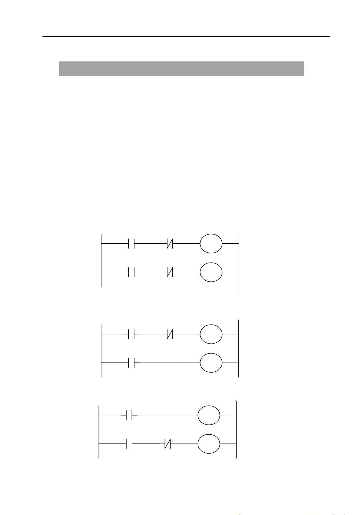
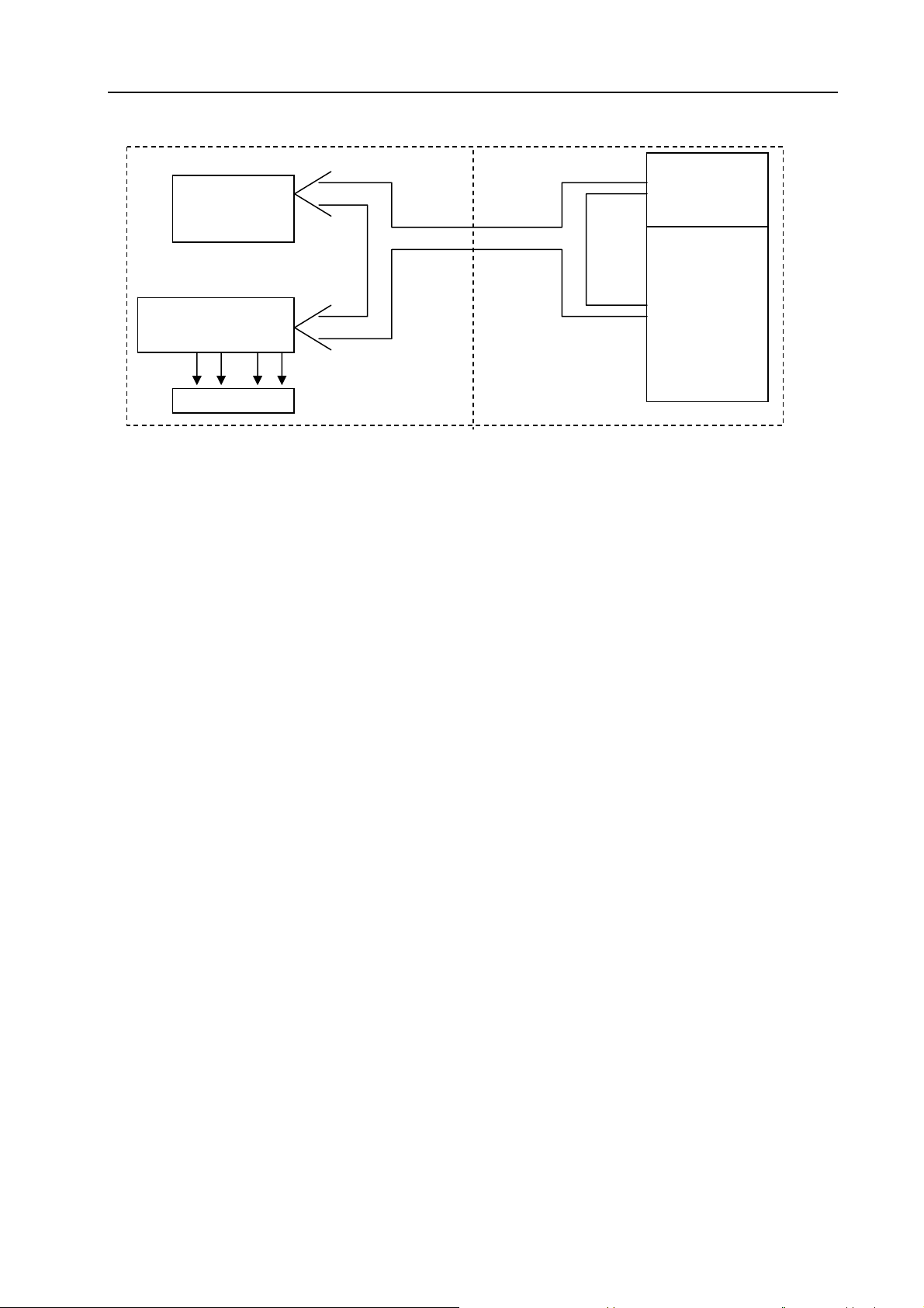
In general relay control circuit, each relay operates at approximately the same time, in the figure
below for example, when relay A operate, the relay D and E operate at approximately the same
time(when contacts B and C are off)., In PLC sequence control, each relay of circuit operates
sequentially. When relay A operates, relay D operates, then relay E(see Fig.2-1). Thus each relay
operates in sequence which can be written as a ladder diagram. (Programmed sequence).
Fig. 2-1(a)
Fig.2.1(b) and (c) illustrate operations varying from the relay circuit to PLC programs.
Fig. 2-1(b)
Fig.2-1(c)
A
A C
A C
A
A
A
B
D
E
B
C
C
C
B
5
Page 16
GSK 25i Milling CNC System User Manual
(1) Relay circuit
In Fig. 2.1(b) and (c), the operations are the same. Turning on A turns on B and C. Turning on C
turns off B.(2) PLC program
In Fig.2.1(b), as in the relay circuit, turning on A turns on B and C, and after one cycle of the PLC
sequence, turns off B. But in Fig.2.1(c), turning on A turns on C, but does not turn on
2.2 Repetitive cycle
The PLC executes the ladder diagram from the beginning to the end . When the ladder diagram
ends, the program starts over from the beginning. This is called repetitive operation.
The execution time from the beginning to the end of the ladder diagram is called the sequence
processing time. The shorter the process time is, the better the signal response becomes.
2.3 Priority of execution(1
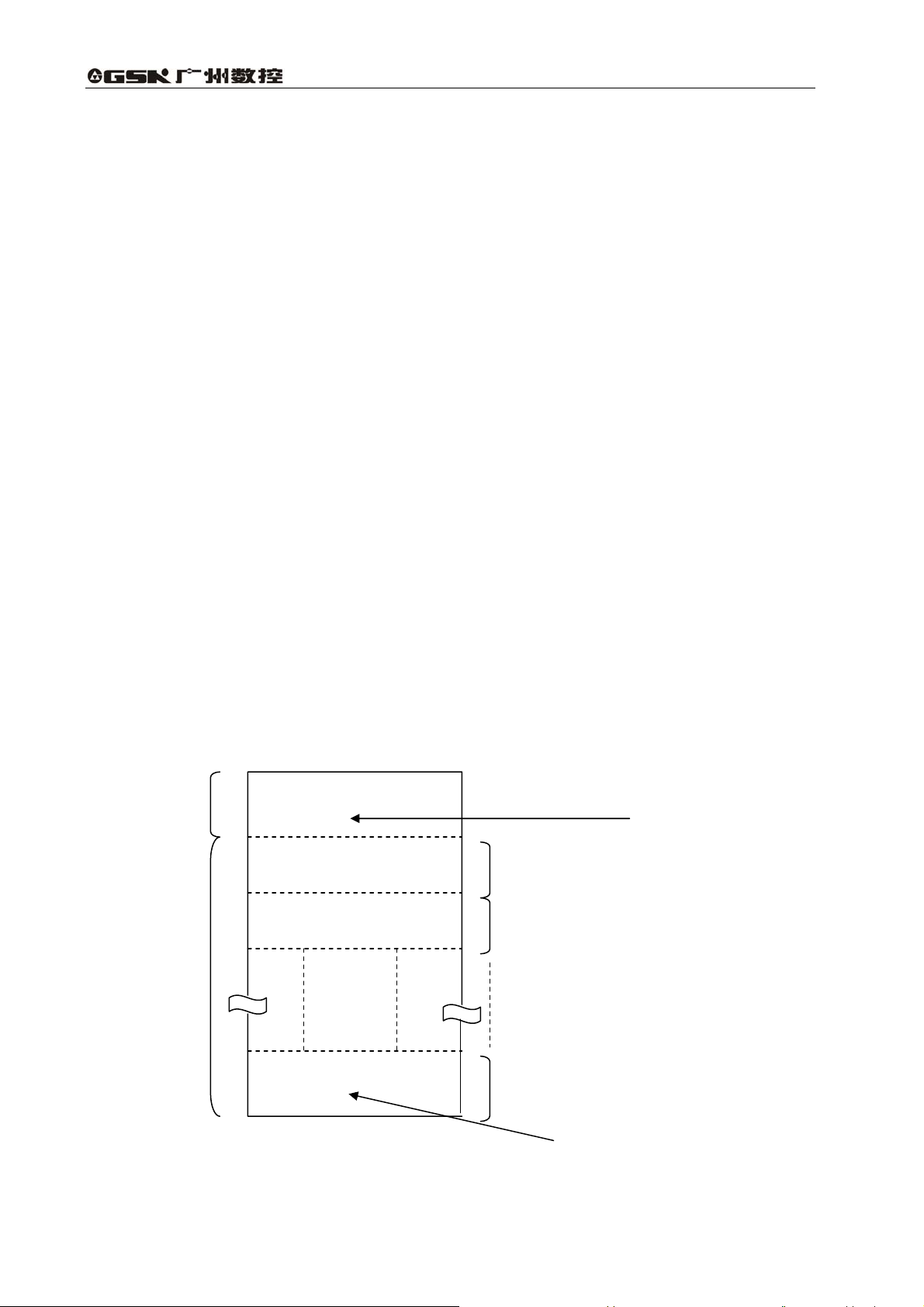
GSK25i PLC consists of two parts: 1st level sequence part, 2nd level sequence part. They have
different execution period.
st
The 1
level sequence part operates every 8 ms, which can deal with the short pulse signal with
st
level, and 2nd level)
high-speed response).
nd
The 2
level sequence part operates every 8*n ms. Here N is a dividing number for the 2nd level
sequence part. The 2nd level sequence part is divided into V part, and every part is executed every
8ms.
st
1
level
sequence part
END1
Specifies the end of the
1st level sequence part
Division 1
Division 2
nd
2
level
sequence program
END2
Division n
Fig. 2-2
Specifies the end of the
2nd level sequence part
6
Page 17
Volume Ⅱ PLC Programming and Connection
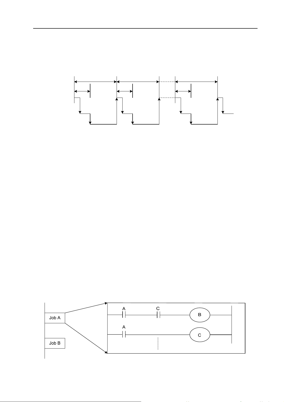
GSK 25i PLC is solely executed in PLC-AVR single chip, and the first 1ms of each 8ms is the
communication time of CNC reading or writing PLC data. The fifth 1ms is the time that the PLC
receives the system control signal(F, X )and uploads the control result data(G, Y p ar am et er )to the
external I/O interface(X, Y), except for the time responding the interruption to exchange the data, the
PLC executes the ladder operation at the rest time.
1stlevel
nd
2
level
CNC use
8 ms
3 ms
Division 1
3 ms
Division 2
8 ms
8 ms
3 ms
Division n
Fig. 2-3
After the last 2nd level sequence part (division n) is executed, the sequence program is executed
again from the beginning. Thus, when the dividing number is n, the cycle of execution is 8*n ms. The
st
1
level sequence operates every 8ms, and the 2nd level sequence every 8*n ms. If the steps of the
st
1
level sequence is increased, the steps of the 2nd level sequence operating within 4ms becomes
less, thereby increasing the dividing number and making the processing time longer. Therefore, it is
desirable to program so as to reduce the 1
st
level sequence to a minimum.
2.4 Sequence program structure
With the conventional PLC, a ladder program is described sequentially. By employing a ladder
language that allows structured programming, the following benefits are derived:
1. A program can be understood and developed easily
2. A program error can be found easily.
3.When an operation error occurs, the cause can be found easily.
Three major structured programming capabilities are supported:
1) Subprogram
A subprogram can consist of a ladder sequence as the processing unit.
Fig. 2-4
7
Page 18
GSK 25i Milling CNC System User Manual
2) Nesting
The Ladder subprograms can call the other ladder subprogram to execute the job.
Main program
Subprogram 2 Subprogram 1
Job A
Job A1
Job A11
Job B
Job An
Job A12
Fig. 2-5
3) Conditional branch
The main program loops and checks whether conditions are satisfied. If a condition is satisfied, the
corresponding subprogram is executed. If the condition is not satisfied, the subprogram is jumpped.
Main program
State 1
Subprogram 1
Process 1
Process 11
State 2
Process 2
Process 12
Fig. 2-6
Process 13
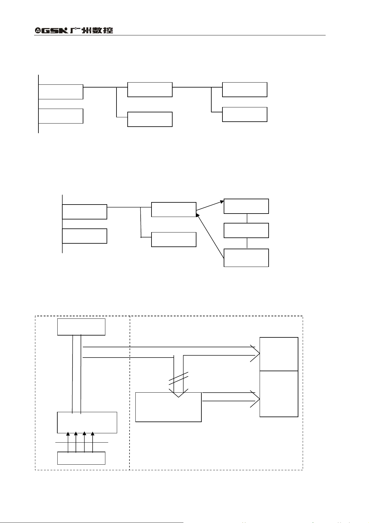
2.5 Processing I/O (input/output) signals
Input signal processing:
CNC
8ms
CNC—PLC
Input signals from
machine tool
IO interface
PLC
2nd sequence part
starting memory
2nd sequence part
input signal memory
Fig. 2-7
1st level
sequence
part
2nd level
sequence
part
8
Page 19
Output signal processing:
CNC
CNC—PLC
Share memory
output memory from
machine tool
8ms
IO interface
2.5.1 Input signal processing
Volume Ⅱ PLC Programming and Connection
PLC
Fig. 2-8
1st level
sequence part
nd
2
level
sequence part
(1)Input memory of NC
The input signals from NC are loaded in memory of NC and are transferred to the PLC at
intervals of 8ms. Since the 1
st
level sequence part directly refer to these signal and process
operations.
(2)Input signal memory to machine tool
The input signal memory stores signals transferred from the machine tool at intervals of 8ms
period. Since the 1
(3)2
nd
level input signal memory
st
level sequence part directly refer to these signal and process operations.
The 2nd level input signal memory is also called as 2nd level synchronous input signal memory.
The stored signals are processed by the 2
synchronizes with that of 2
nd
level sequence part.
Input memory Signals from NC and machine tool are transferred to the 2
memory only at the beginning of execution of the 2
nd
2
level synchronous input signal memory does not change from the beginning to end of the
execution of the 2
nd
level sequence part.
nd
level sequence part. State of the signals set this memory
nd
level input signal
nd
level sequence part. Therefore, the state of the
2.5.2 Output signal processing
(1)NC output memory
The output signals are transferred form the PLC to the NC output memory at intervals of 8ms.
(2)Output signals to machine tool
Output signal to the machine tool from PLC output signal memory to the machine tool at intervals
of 8ms.
9
Page 20
GSK 25i Milling CNC System User Manual
Note:
The state of the NC input memory, NC output memory, input signals from machine, input/output
memory signals to machine can be checked by using the PC self-diagnosis function. The
self-diagnosis number specified is the address number used by the sequence program.
2.5.3 Synchronous processing the short pulse signal
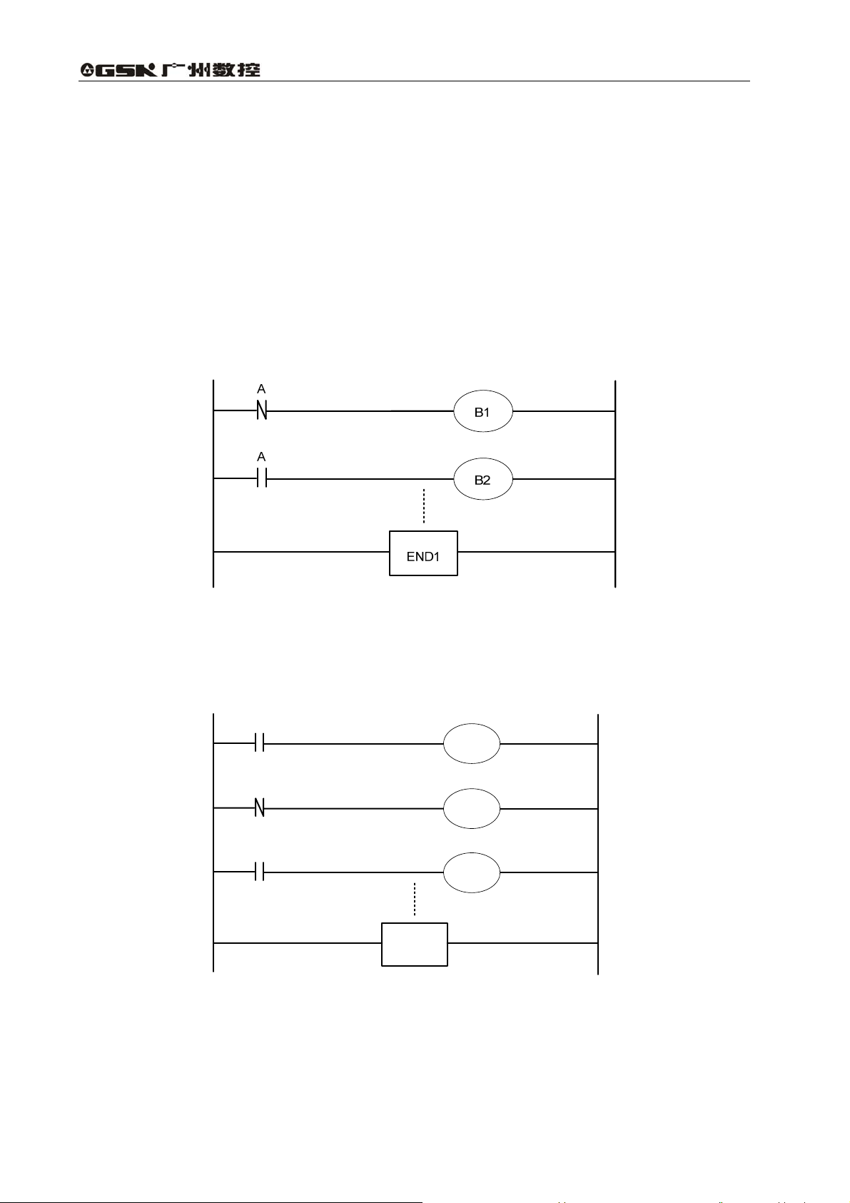
1st program can process the short pulse signal. When the short pulse signal change is less than
8ms, i.e.when the system executes the 1
followings.
st
program, the input signal state can change to cause the
Fig. 2-9
When A=0 and B1=1,A becomes 1, at the moment, the system executes the next
ladder statement to make B2=1. so, B1 and B2 become 1.
A
R
R
B1
R
B2
END1
Fig. 2-10
When the medium relay R synchronously processes the signal A, B1, B2 are not 1 at the same
time.
10
Page 21
Volume Ⅱ PLC Programming and Connection
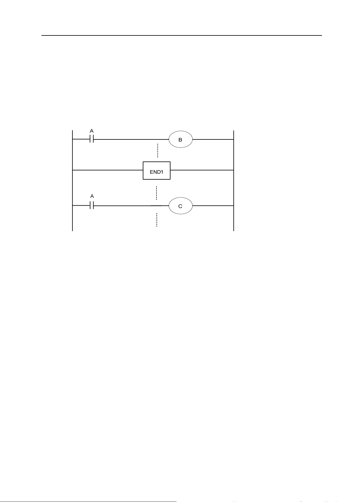
2.5.4 Difference state of signals between 1st level and 2nd level
The state of the same input signal may be different in the 1st level and 2nd level sequences. That
is, at 1
performed using the 2
sequence execution at the worst, compared with a 1
This must be kept in mind when writing the sequence program.
st
level, processing is performed using input signal memory and at 2nd level, processing is
nd
level synchronous input signal memory. Therefore, it is possible for a 2nd level
st
level input signal.
nd
2
division of 2nd
level sequence part
Fig. 2-11
When the processing is 1st 8ms, A=1, and B=1 after 1st sequence part is executed. At the same
time, 2nd sequence part is started to execute A=1 is stored to the 2nd sequence part and the 1st
division of 2nd sequence part is executed.
When the processing is 2nd 8ms, A=0, and B=0 after 1st sequence part is executed. And then
2nd division of 2nd sequence part is executed, at this time, A is still 1. So C=1.
So, B and C are different.
2.6 Interlocking
Interlocking is externally important in sequence control safety.
Interlocking with the sequence program is necessary. However, interlocking with the end of the
electric circuit in the machine tool magnetic cabinet must not be forgotten. Even though logically
interlocked with the sequence program (software), the interlock will not work when trouble occurs in
the hardware used to execute the sequence program. Therefore, always provide an interlock inside
the machine tool magnetic cabinet panel to ensure operator safety and to protect the machine from
damage.
11
Page 22
GSK 25i Milling CNC System User Manual
3 Address
An address shows a signal location. Addresses include input/output signals with respect to the
machine, the input/output signals with respect to the CNC, the internal relays, the meters, the keep
relays, and data table. Each address consists of an address number and a bit number. Its serial
number regulations are as follows:
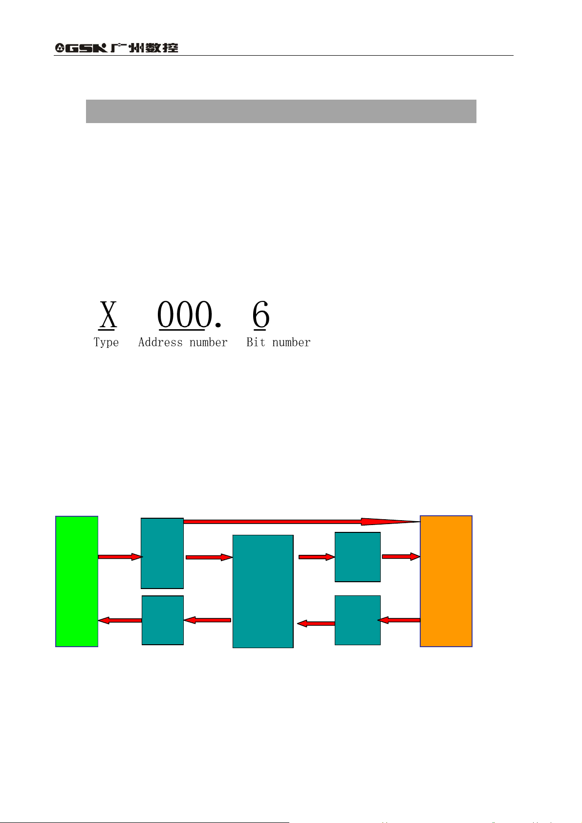
Address regulations:
The address comprises the address type, address number and the bit number in the format as
shown below:
Type: including X, Y, R, F, G K, A, D ,C, T
Address number: decimal serial number stands for one byte.
Bit number: octal serial number, 0~7 stands for 0~7 bit of byte of front address number
GSK25i PLC address type is as follows Fig.3-1:
Emergency stop, jump and other
high-speed signals
Machine to PLC
Input signal
MT
PLC to machine
Output signal
X
Y
Nesting
PLC
Fig. 3-1
G
F
PLC to NC
NC to PLC
25i
CNC
12
Page 23

Volume Ⅱ PLC Programming and Connection
Table 3-1
Address Address explanation Address range
X machine→PLC(128 bytes)
Y PLC→machine(128 bytes)
F CNC→PLC(256 bytes)
G PLC→CNC(256 bytes)
R Internal relay(1100 bytes)
D Data register(1860 bytes)
C Counter (400 bytes)
T Timer (200 bytes)
A Timer preset data register (32 bytes)
K
Keep relay(32 bytes) K0~K31
3.1 Machine →PLC address(X)
X0~X127
Y0~Y127
F0~F255
G0~G255
R0~R1099
D0~D1859
C0~C 399
T0~T199
A0~A31
X addresses of GSK25i PLC are divided into two:
1. X addresses are assigned to IO input interface.
2. X addresses are assigned to the input press keys on MDI panel.
3. X addresses are assigned to other external interfaces, such as the spindle, MPG control signal
input.
3.1.1 Assignment of IO module X address
The addresses are from X9 to X119. Its type is INT8U, 111 types.
The signal specification of X addresses can be customized by customer according to the actual
operation. X addresses are used to connect the machine tool with the ladder. For the initial definition
of input address, see Chapter Four Connection.
3.1.2 Assignment of MDI panel X address
The addresses are from X0 to X8, 9 bytes. They correspond to the press keys on MDI panel.
The corresponding relationship between them and the press keys on the standard panel is as Fig.
3-2:
13
Page 24

GSK 25i Milling CNC System User Manual
Table 3-2
INPUT KEY ON
OPERATION PANE L
Auto mode X0.0 -Z X3.5
Edit mode X0.1 -4 X3.6
MDI mode X0.2 -5 X3.7
Manual mode X0.3 Spindle CW X4.0
MPG mode X0.4 Spindle stop X4.1
Zero mode X0.5 Spindle CCW X4.2
DNC mode X0.6 Spindle orientation X4.3
USER1 X0.7
Single block X1.0
Jump X1.1
Machine lock X1.2
Auxiliary lock X1.3
+4 X1.4
+Z X1.5
-Y X1.6 Tool magazine infeed X5.3
+5 X1.7 Tool retraction X5.4
Dry run X2.0 Tool change manipulator X5.5
Overtravel release X2.1 Tool magazine CW X5.6
Optional stop X2.2 Tool magazine zero X5.7
Program restart X2.3 Clamp/release X6.0
+X X2.4 USR2 X6.1
Rapid X2.5 USR3 X6.2
Step X2.6 USR4 X6.3
-X X2.7 Feed hold X6.4
Cooling X3.0 Cycle start X6.5
Lubricating X3.1 Tool magazine CCW X6.6
Chip removal
Working light
+Y X3.4 Emergency stop X8.4
PLC
ADDRESS
X3.2 Feedrate override, up to
X3.3 Spindle override, up to
INPUT KEY ON
OPERATION PANE L
F0/0.001
25%/0.01
50%/0.1
100%/1
24-gear(no output light)
16-gear(no output light)
PLC
ADDRESS
X4.4
X4.5
X4.6
X4.7
X7.0-X7.4
X8.0-X8.3
14
Page 25

Volume Ⅱ PLC Programming and Connection
3.1.3 MPG signal input X address
Table 3-3
MPG signal input
HDC0_STP (MPG emergency stop signal)
HDC0_MX100(MPG federate override)
HDC0_MX10 (MPG federate override)
HDC0_MX1 (MPG federate override)
HDC0_5 (5th axis)
PLC address
X121.0
X120.0
X120.1
X120.2
X120.3
HDC0_4 (4th axis)
HDC0_Z (Z axis)
HDC0_Y (Y axis)
HDC0_X (X axis)
X120.4
X120.5
X120.6
X120.7
3.2 PLC→machine side address(Y)
Y addresses of GSK25i PLC are divided into three:
1. Y addresses are assigned to IO input interface.
2. Y addresses are assigned to the indicators on MDI panel.
3. Y addresses are assigned to the indicators on MPG.
3.2.1 Y address of I/O output interface
The addresses are from Y8 to Y119. Its type is INT8U, 112 types.
The signal specification of Y addresses can be customized by customer according to the actual
operation. Y addresses are used to connect the machine tool with the ladder. For the initial definition
of input address, see Chapter Four Connection.
3.2.2 Assignment of IO module Y address
The addresses are from Y0 to Y7, 8 bytes. They correspond to the indicators on MDI panel, and
their signal definitions cannot be changed by user.
Addresses and indicators are as follows Table.3-4:
15
Page 26

GSK 25i Milling CNC System User Manual
Table 3-4
OUTPUT KEY ON
OPERATION PANE L
PLC
ADDRESS
OUTPUT KEY ON
OPERATION PANE L
PLC
ADDRESS
Auto key indicator Y0.0 -Z key indicator Y3.5
Edit key indicator Y0.1 -4 key indicator Y3.6
MDI key indicator Y0.2 -5 key indicator Y3.7
Manual key indicator Y0.3 Spindle CW key indicator Y4.0
MPG key indicator Y0.4 Spindle stop key indicator Y4.1
Zero key indicator Y0.5 Spindle CCW key indicator Y4.2
DNC key indicaor Y0.6 Spindle orientation key indicator Y4.3
USER1 key indicaor Y0.7
Single block key indicaor Y1.0
Jump key indicator Y1.1
Machine lock indicator Y1.2
F0/0.001 key indicator
25%/0.01 key indicator
50%/0.1 key indicator
100%/1 key indicator
Y4.4
Y4.5
Y4.6
Y4.7
Auxiliary lock indicator Y1.3 Tool magazine infeed key indicator Y5.3
+4 key indicator Y1.4 Tool retraction key indicator Y5.4
+Z key indicator Y1.5 Tool change key indicator Y5.5
-Y key indicator Y1.6 Tool magazine CW key indicator Y5.6
+5 key indicator Y1.7 Tool magazine zero key indicator Y5.7
Dry run key indicator Y2.0 Clamp/release tool key indicator Y6.0
Overtravel release key indicator Y2.1 USR2 key indicator Y6.1
Optional stop key indicator Y2.2 USR3 key indicator Y6.2
Program restart key indicator Y2.3 USR4 key indicator Y6.3
+X key indicator Y2.4 Feed hold key indicator Y6.4
Rapid key indicator Y2.5 Cycle start key indicator Y6.5
Step key indicator Y2.6 Tool magazine CCW key indicator Y6.6
-X key indicator Y2.7 X zero return indicator Y7.0
Cooling key indicator Y3.0 Y zero return indicator Y7.1
Lubricating key indicator Y3.1 Z zero return indicator Y7.2
Chip removal key indicator Y3.2 4
Working light key indicator Y3.3 5
th
zero return indicator Y7.3
th
zero return indicator Y7.4
+Y key indicator Y3.4 System alarms Y7.6
3.2.3 MPG signal light output
MPG signal light output
Y120.0
3.3 PLC→CNC address(G)
Addresses are from G0 to G255. Type: INT8U,256 bytes. G addresses are the signals from PLC
to NC, and these signals have been defined in designing the CNC system and cannot be modified.
16
Page 27
Volume Ⅱ PLC Programming and Connection
The concrete is referred to Appendix 1.
3.4 CNC→PLC address(F)
A ddresses are from F0 to F255. Type: INT8U,256 bytes. F addresses are the signals from NC to
PLC, and these signals have been defined in designing the CNC system and cannot be modified. The
concrete is referred to Appendix 1.
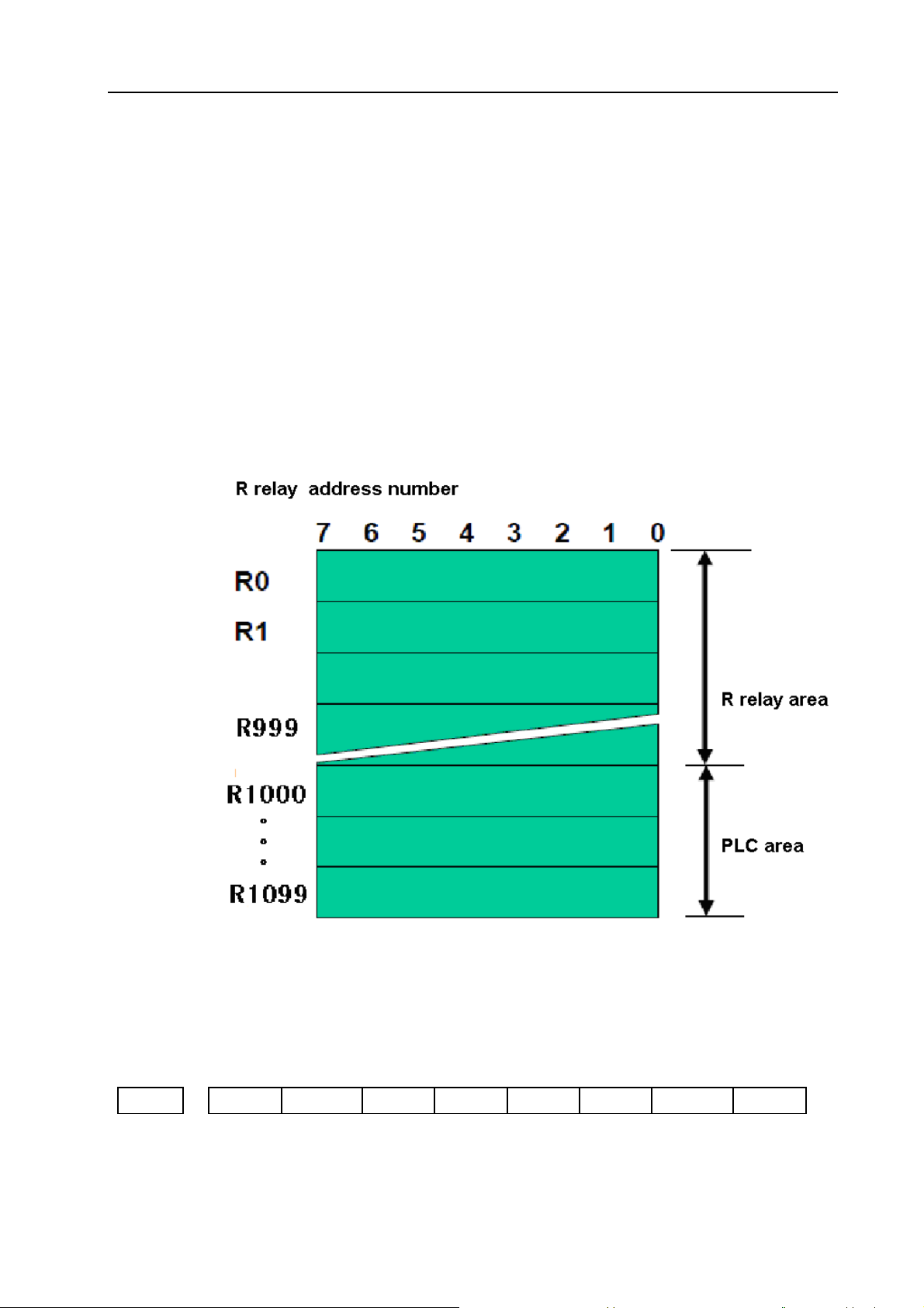
3.5 Internal relay address(R)
The address area is cleared to zero when the power is turned on.
Type: INT8U, with 1100 bytes.
Fig. 3-2
Note: the addresses from R1000 are used by PLC. For example: ADDB, SUBB, COMB functional command
operation result are output to the register:
#7 #6 #5 #4 #3 #2 #1 #0
R1000 Overflow Negative Zero
Fig. 3-3
17
Page 28
GSK 25i Milling CNC System User Manual
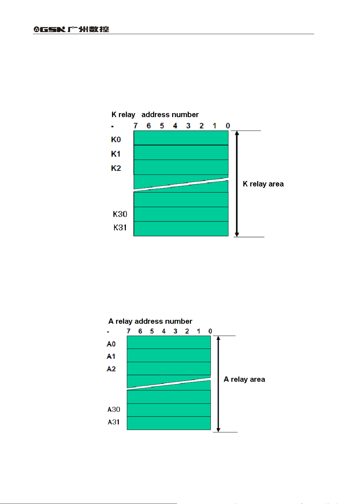
3.6 Address of keep relay(K)
The area is used for the keep relays and PLC parameters. Since this area is nonvolatile, the
content of the memory do not disappear even when the power is turned off.
Type: INT8U, with 32 bytes
Fig. 3-4
3.7 Addresses(A) for message selection
The address area is cleared to zero when the power is turned on.
Type: INT8U, with 32 bytes.
18
Fig. 3-5
Page 29
Volume Ⅱ PLC Programming and Connection
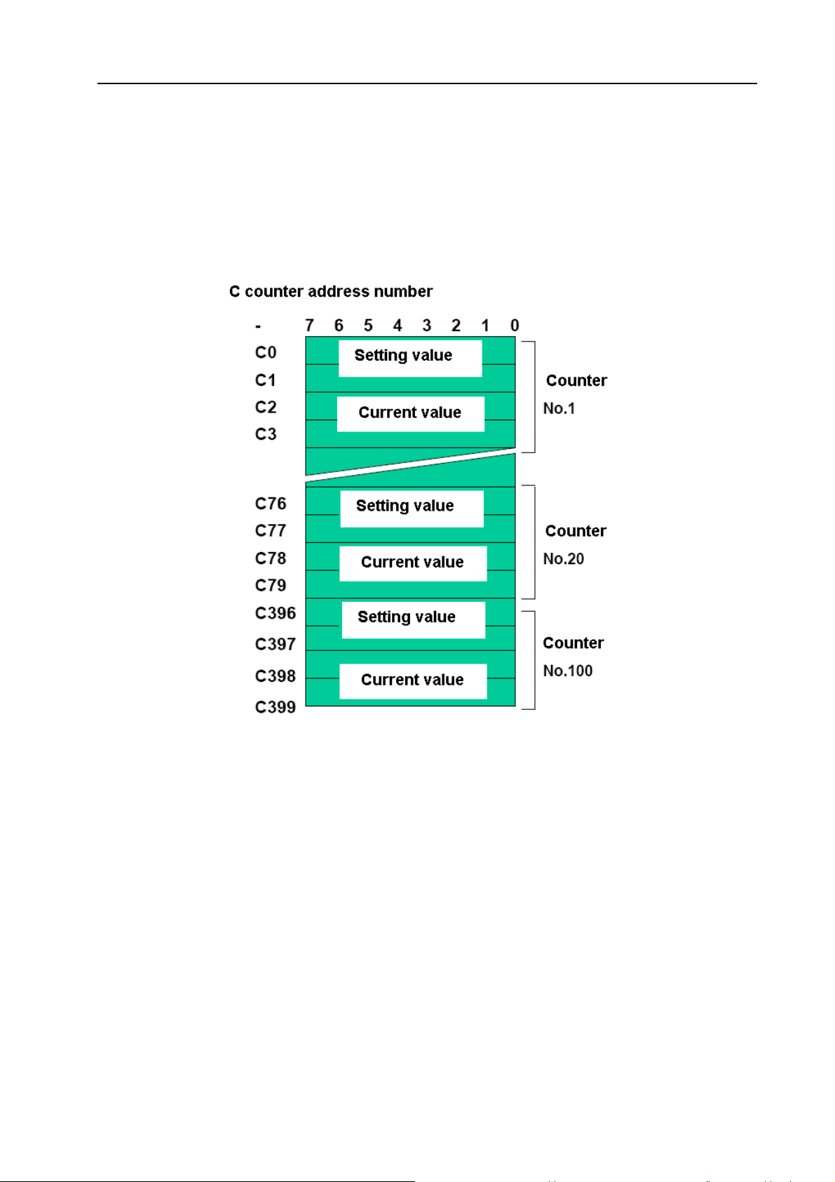
3.8 Address of counter(C)
The area is used as storing current counting value in meter.
Type: 400 bytes.
C1~C100: count range: 0~65535, can set increase/reducing count, and the counting value
does not disappear even when the power is turned off.
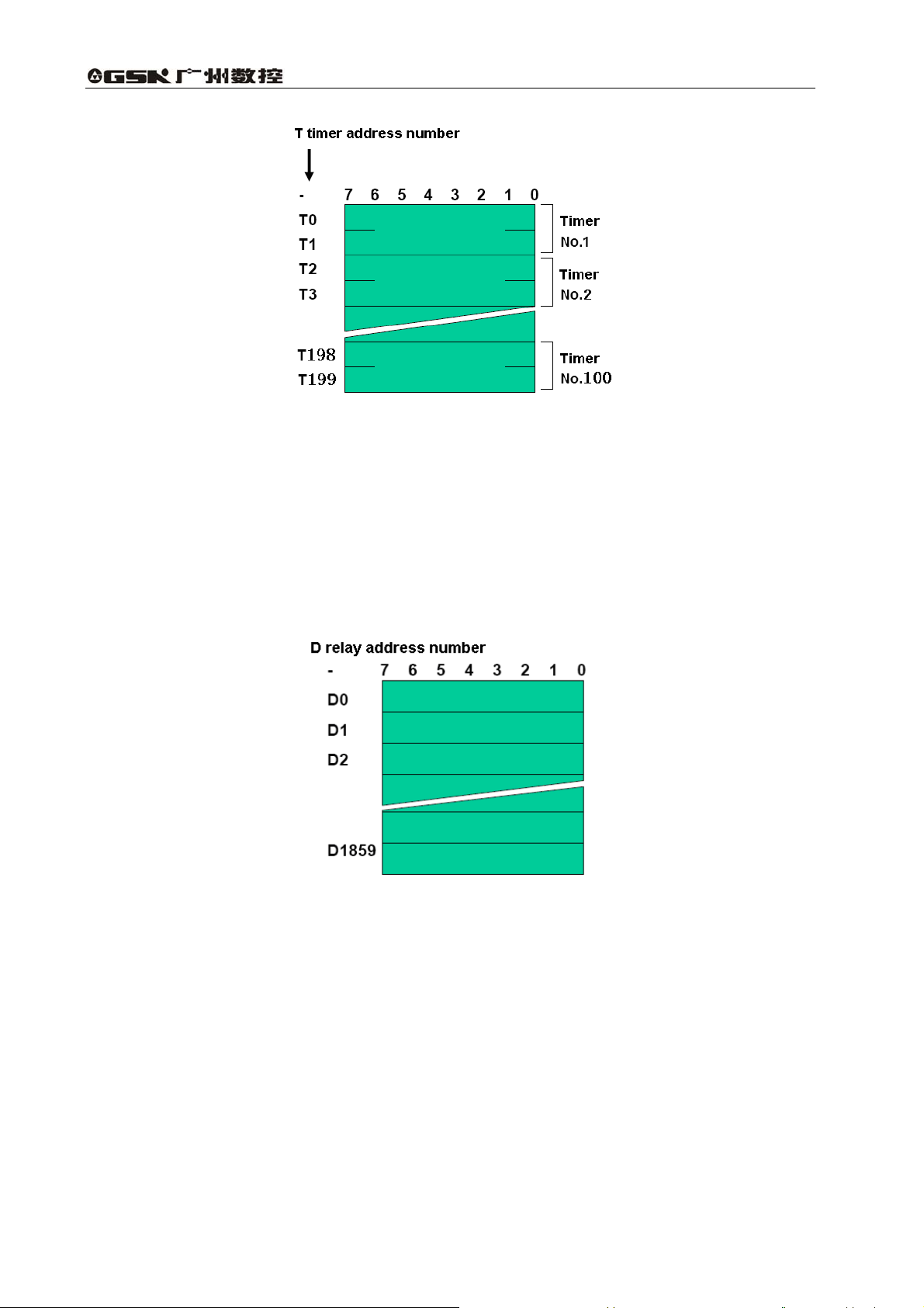
3.9 Address of timer (T)
Type: 200 bytes.
T1~T100,The timing value does not disappear even when the system is turned off.
.
Fig. 3-6
19
Page 30
GSK 25i Milling CNC System User Manual
Fig. 3-7
3.10 Address(D)of data table
Each data register has 8-bit, two continuous data registers can store 16-bit data, four continuous
data registers can store 32-bit data.
The content of the memory do not disappear even when the power is turned off.
Number of data table:D0~D1859,1860 bytes.
Fig. 3-8
3.11 Label address(L)
Label addresses are used to specify jump destination labels and LBL labels in JMPB instructions.
Range: L0~L9999
3.12 Subprogram numbers(P)
Subprogram numbers are used to specify jump destination subprogram labels and SP instruction
subprogram labels in CALL instruction.
Range: P0~P511.
20
Page 31

Volume Ⅱ PLC Programming and Connection
4 PLC Basic Instruction
Designing a sequence program begins with writing a ladder diagram. The ladder diagram is
written using relay contact symbols and functional instruction code. Logic written in the ladder
diagram is entered as a sequence program in the Programmer. There are two sequence program
entry methods. One is the entry method with the mnemonic language (PLC instructions such as RD,
AND, OR). The other is the relay symbols of the ladder diagram. When the relay symbol method is
used, the ladder diagram format can be used and programming can be performed without
understanding the PLC instruction format.
Actually, however, the sequence program entered by the relay symbol method is also internally
converted into the instruction corresponding to the PLC instruction.
The basic instructions are often used when the sequence program is designed, and the execute
one-bit operation.
GSK25i basic instructions are as follows(see Table 4-1):
Table 4-1
Instruction Function
LD
LDI
OUT
OUTI
AND
ANI
OR Induces a logical sum.
ORI
Shifts left the content by one bit in register and sets the state of a
specified signal in ST0.
Shifts left the content by one bit in register and sets the logic state
of a specified signal in ST0.
Outputs the results of logic operation to a specified address.
Inverts the results of logical operations and output it to a specified
address.
Induces a logical product.
Inverts the state of a specified signal and induces a logical
product.
Inverts the state of a specified signal and induces a logical sum.
ORB
ANB
Sets the logical sum of ST0 and ST1, and shifts the stack register
right by one bit.
Sets the logical product of ST0 and ST1, and shifts the stack
register right by one bit.
21
Page 32

GSK 25i Milling CNC System User Manual
4.1 LD, LDI, OUT, OUTI command
Instructions and functions(Table 4-2):
Table 4-2
Instruction Function
LD
LDI
OUT
OUTI
Instruction specifications:
z WRT, WRT. NOT are the output relay, internal relay instructions. They cannot be used to input
relay.
z The parallel WRT instruction can be continuously used many times.
Programming
LD X002.1
OUT Y003.7
LDI F100.3
OUT G120.0
Shifts left the content by one bit in register and sets the state of a specified
signal in ST0.
Shifts left the content by one bit in register and sets the logic state of a
specified signal in ST0.
Outputs the results of logic operation to a specified address.
Inverts the results of logical operations and output it to a specified address.
4.2 AND, ANI command
Instructions and functions(Table 4-3):
Table 4-3
Instruction Function
AND Induces a logical product.
ANI Inverts the state of a specified signal and induces a logical product.
Instruction specifications:
z AND, ANI can connect with one contact in serial. The serial contact numbers are not limited
and they can be used many times.
Programming
LD X002.1
ANI F100.3
AND X008.6
OUT Y003.7
22
Page 33

Volume Ⅱ PLC Programming and Connection
4.3 OR, ORI command
Instructions and functions (Table 4-4)
Table 4-4
Instruction Function
OR Induces a logical sum.
ORI Inverts the state of a specified signal and induces a logical sum.
Instruction specification:
z OR, ORI can connect with one contact in parallel.
z OR, ORI begins from their step, which can connect with the mentioned step in parallel.
Programming:
LD X002.1
ORI F100.3
OUT Y003.7
4.4 ORB command
Instruction and function(Table 4-5):
Table 4-5
Instruction Function
ORB Sets the logical sum of ST0 and ST1, and shifts the
stack register right by one bit.
Instruction specification:
z ORB a sole instruction without other address.
Programming
LDI F100.3
AND F100.6
ORB
OR R022.1
OUT Y003.7
LD X002.1
ANI X002.2
As the above figure, there are three branch circuit ①,②, from left bus to the node N1, among ③
which ①, is circuit block in series; when there is the serial circuit block in the par② allel from the bus
to node or between nodes, the following branch end uses LD instruction except for the first branch.
23
Page 34

GSK 25i Milling CNC System User Manual
The branch is not serial circuit block to use OR instruction. ③
ORB and ANB are instructions without operation components, indicating the OR, AND
relationship between circuit blocks.
4.5 ANB command
Instruction and function(Table 4-6):
Table 4-6
Instruction Function
ANB Sets the logical product of ST0 and ST1, and shifts the stack register right by one bit.
Instruction specification
z When the branch loop (parallel loop block) is connected to the previous loop in series, use
ANB instruction. The starting point of branch uses LD, LDI instruction, after the parallel loop
block ends, ANB instruction is connected to previous loop in series.
z ANB a sole instruction without other address.
Programming
LD X002.1
ORI F100.3
ORI X011.0
LD R100.0
ANI R100.3
LD G003.3
AND R009.7
ORB ← ⑴
ANB ← ⑵
OUT Y003.7
As the above figure and instruction list, ORB reportS the series circuit block in block is ⑴②
connected parallel ANB reports the block and are connected in series. ⑵①②
24
Page 35

Volume Ⅱ PLC Programming and Connection
5 PLC Functional Instructions
Basic instructions such as controlling operations of machine tool are difficult to program,
therefore, functional instructions are available to facilitate programming.
25i functional instruction as follows(Table 5-1):
Table 5-1
No. Instruction Processing
0 END1 End of a 1st level ladder program
1 END2 End of a 2nd level ladder program
2 TMR Timer processing
3 TMRB Fixed timer processing
4 TMRC Timer processing
5 DECB Binary decoding
6 CTR Counter processing
7 CTRC Counter processing
8 ROTB Binary rotation control
9 CODB Binary code conversion
10 MOVE Data transfer after logic AND
11 MOVOR Data transfer after logic OR
12 MOVB Transfer of 1 byte
13 MOVW Transfer of 2 bytes
14 MOVN Transfer of an arbitrary number of bytes
15 PARI Parity check
16 DCNVB Data conversion
17 COMPB Binary comparison
18 COIN Coincidence check
19 DSCHB Binary data search
20 XMOVB Binary indexed data transfer
21 ADDB Binary addition
22 SUBB Binary subtraction
23 MULB Binary multiplication
24 DIVB Binary division
25 NUMEB Binary constant definition
26 DIFU Edge Up detection
25
Page 36

GSK 25i Milling CNC System User Manual
27 DIFD Failing edge detection
28 SFT Register shift
29 EOR Exclusive OR
30 AND Exclusive AND
31 OR Exclusive OR
32 NOT Logic NOT
33 COM Common line control
34 COME End of common line control
35 JMP Jump
36 JMPE End of a jump
37 CALL Conditional subprogram call
38 CALLU Unconditional subprogram call
39 JMPB Label jump
40 JMPC Label jump
41 LBL Label
42 SP Subprogram
43 SPE End of a subprogram
5.1 END1(1
st
level sequence program end)
Function:
It must be specified once in a sequence program, either at the end of the 1
the beginning of the 2
nd
level sequence when there is no 1st level sequence. It can write 500 steps.
Format:
Fig. 5-1
Command table format:
Table 5-2
No. Command Operand Remark
1 FUNC 0 End of 1st level program
st
level sequence, or at
26
Page 37

Volume Ⅱ PLC Programming and Connection
5.2 END2(2
Function:
Specify at the end of 2
Format:
Command table
Note: Only the subprograms of SP head, SPE end are added to the ladder following END2, otherwise,
the system prompts the wrong.
nd
level sequence program end)
nd
level sequence.
Fig. 5-2
Table 5-3
No. Command Operand Remark
1 FUNC 1 End of 2nd level program
5.3 TMR(Timer)
Function:
This is an on-delay timer.
Format:
Command table format:
No. Command Operand Remark
1 LD
2 FUNC 2 Timer command TMR
3 PRM ○○○ Timer number
4 OUT
Fig. 5-3
Table 5-4
○○○○.○
○○○○.○
Exclusive conditions
Timer relay
27
Page 38

GSK 25i Milling CNC System User Manual
Control conditions: ACT=0,turns off timer relay.
ACT=1,start TIMER.
Concrete working conditions are as follows:
Fig. 5-4
Parameter
:
Timer number:reports with ○○○, ○○○ are the number(1~100).
Output:
OUT : timer relay.
OUT =1 ACT processing is done and reaches the preset time, the timer relay
processing is done, OUT =1.
OUT =0 ACT processing is not done or has not reached the preset time, the timer
relay is turned off, OUT =0.
Setting timer:
For timer TMR delay time setting value, 1
the maximum setting value is 3145680ms; when the value less than 48ms is omitted; 21
th
to 100
timer take 8ms as the unit setting and the maximum setting value is 524280ms,
and the value less than 8ms is omitted.
For example: when the 1
st
timer value is 100ms, the set actual value is 96ms, 100=48×2+4 and the
remainder 4 is omitted.
st
th
-20
timer take 48ms as the unit setting, and
st
5.4 TMRB(fixed timer)
Function:
The timer is used as a fixed on-delay timer.
Format:
Fig. 5-5
28
Page 39

Command table format:
Volume Ⅱ PLC Programming and Connection
Table 5-5
Control condition:
ACT=0:turn off timer relay.
ACT=1:start timer.
Parameter:
No. Command Operand Remark
1 LD
2 FUNC 3 Fixed timer TMRB
3 PRM ○○○ Timer number
4 PRM ○○○○ Timer time
5 OUT
○○○○.○
○○○○.○
Exclusive conditions
Timer relay
Timer number set timer number of the fixed timer (1~100).
Timer time setting preset time(set delay time 8ms~999999ms)
The range of the preset time is 8ms nd the remainder is omitted. For example: the preset is
38ms, 38==8*4+6, and the remainder is discarded and the actual setting time is only 32ms.
Timer relay
:
OUT : timer relay.
OUT=1 ACT processing is done and reaches the preset time, the timer relay
processing is done, OUT=1.
OUT=0 ACT processing is not done or has not reached the preset time, the timer
relay is turned off, OUT=0.
Note: TMR timer number can set the timer parameter to be modified, and it is saved when power-off;
the fixed timer number of TMRB is a timer parameter directly processed in the system internal,
is saved when power off, and cannot be modified by the user.
5.5 TMRC(timer)
Function:
TMRC is the on-delay timer using the address to set the fixed time. The processing data type is
the binary data.
Format:
Fig. 5-6
29
Page 40

GSK 25i Milling CNC System User Manual
Command table format:
Control condition:
ACT=0:turns off the timer relay.
ACT=1:starts the timer.
No. Command Operand Remark
1 LD
2 FUNC 4 TMRC command
3 PRM ○ Timer precision
4 PRM ○○○○ Timer time address
5 PRM ○○○○ Time register
6 OUT
Table 5-6
○○○○.○
○○○○.○
Exclusive conditions
Timer relay
Parameter:
Timer precision: timer precision, parameter setting value, setting time and error are
as follows:
Table 5-7
Timer accuracy Setting value Setting time Timer accuracy error
8 ms 0 8 ms to 52428 ms 0 to ±8ms
48 ms 1 48 ms to 3145680 ms 0 to ±8ms
1s 2 1s to 65535 s 0 to ±8ms
Setting time address: the first address of the timer set time filed.
Timer register address: the first address of a specified continuous four-byte R is used as
the system working area and is used in timer working.
Timer relay:
OUT : timer relay.
OUT =1 ACT processing is done and reaches the preset time, the timer relay
OUT =0 ACT processing is not done or has not reached the preset time, the timer
30
Fig. 5-7
processing is done,,OUT =1.
relay is turned off, OUT =0.
Page 41

Volume Ⅱ PLC Programming and Connection
5.6 DECB(binary decode)
Function:
DECB decodes the binary data with 1, 2, 4 bytes, the corresponding output data is 1 when one
of the specified 8-digit continuous data is equal to the code data, and 0 when not.
The command is used to decode M or T function.
Format:
Control condition:
ACT=0:resets all the output data bits.
ACT=1:decodes data. Results of processing is set in the output data address.
Command table format:
Parameters:
Format specification: Set the size of code data to the 1
No. Command Operand Remark
1 LD
2 FUNC 5 DECB command
3 PRM ○ Format specification
4 PRM ○○○○ Code data address
5 PRM ○○○○ Decode designation
6 PRM ○○○○ Decode output address
Fig. 5-8
Table 5-8
○○○○.○
Control condition
st
digit of the parameter.
0001:code data is in binary format of 1-byte length.
0002:code data is in binary format of 2-byte length.
0004:code data is in binary format of 4-byte length.
Code data address: specify an address of a memory code data.
Decoding designating: designate the first number of the decoding 8 continuous codes.
Decoding result address: designate an address of the output decoding result covering
1-byte. The decoding result of the designated number is output to
31
Page 42

Example:
GSK 25i Milling CNC System User Manual
the 0-digit of the address, and the decoding result of the specified
number +1 is output to 1-digit and the continuous 8 numbers are
done like this.
Fig. 5-9
After F7.0 is turned on, 2-byte data of F10~F11 are decoded. When the decoding data is in the
range 3~10, the corresponding bit of R200 becomes 1.
5.7 CTR(counter)
Function:
The counter data type is the binary format and has the following functions to meet its application.
1) Preset counter
Output a signal when the preset count is reached.
2) Ring counter
Upon reaching the preset count, returns to the initial value by issuing another count signal.
3) Up/down counter
The count can be either up or down.
4) Selection of initial value
32
Select the initial value as either 0 or 1.
Page 43

Format:
Volume Ⅱ PLC Programming and Connection
Command table format:
No. Command Operand Remark
1 LD
2 LD
3 LD
4 LD
5 FUNC 6 CTR
6 PRM ○○○○ Counter number
7 OUT
Control conditions:
CN0: Specify the initial value
UPDOWN: specify up or down counter:
Fig. 5-10
Table 5-9
○○○○.○
○○○○.○
○○○○.○
○○○○.○
○○○○.○
CN0
UPDOWN
RST
ACT
Count up output
CN0=0 begins the value of the counter with 0.
CN0=1 begins the value of the counter with 1.
UPDOWN=1 Up counter(the initial value is set by CN0).
UPDOWN=0 Down counter(the counter begins with te preset value).
RST : reset
RST=0 Releases reset.
RST=1 Enables reset. When OUT is reset to 0, the counter value is reset
to the initial value(when the Up counter is done, it is 0 or 1
accoridng to CN0 setting), when it is Down counter, it is the preset
value of the counter).
ACT : Counter signal
ACT=1:counter is madeby catching the rise of ACT.
ACT=0:counter does not operate. OUT does not change.
33
Page 44

GSK 25i Milling CNC System User Manual
Parameter:
Counter number : specify the counter number and it is 1~100.
Output:
OUT : when the count is up to a preset value, the Up count reaches the maximum value
or the minmum value, OUT = 1.
Note: When the counter is Up edge, the system executes the count. When the count number is repetitive,
the operation is unexpected.
The current, preset value of the counter is set in 【Counter】 of 【PLC parameter】 in PLC window.
5.8 CTRC(counter)
Function:
The data in the counter is binary and the counter has the following functions.
1) Preset counter
Preset the count value and if the count reaches this preset value, outputs to show that.
2) Ring counter
This is the ring counter which is reset to the initial value when the count signal is input after the
count reaches the preset value.
3) Up/down counbter
This is the reversible counter to be used as both the up counter and down counter.
4) Selection of the initial value
Either 0 or 1 can be selected as the initial value.
Format:
count up output
Counter preset address
counter register addess
34
Fig. 5-11
Page 45

Command table format:
Volume Ⅱ PLC Programming and Connection
Table 5-10
Control conditions:
No. Command Operand Remark
1 LD
2 LD
3 LD
4 LD
5 FUNC 7 CTRC command
6 PRM ○○○○ Counter preset address
7 PRM ○○○○ Counter register address
8 OUT
CN0 : Specifying the initial value
UPDOWN :Spcifying up or down counter
RST : reset
○○○○.○
○○○○.○
○○○○.○
○○○○.○
○○○○.○
CN0=0 the count value starts with 0.
CN0=1 the count value starts with 1.
UPDOWN=1 Up counter.
UPDOWN=0 Down counter.
Count up output
CN0
UPDOWN
RST
ACT
Parameter:
Counter preset value address: the first address of the counter preset value field with 2-byte is
Counter register address: The first address of the counter register field is set, the continuous
RST=0 release reset.
RST=1 enable reset. When OUT is set to 0 the count value is reset to the
initial value.
ACT : count signal
ACT=1:the counter operates at the rise of this signal.
ACT=0:the counter does not operate, OUT does not change.
set. The continuous 2-byte memory space from the first
address is required for this field and the field D is binary and its
range is 0~32767.
4-byte memory space from the first address is required for this field
and the field D is normally used. The first two-byte is accumulated
value and the second two –byte is the system working area.
35
Page 46

GSK 25i Milling CNC System User Manual
Note: When field R is specified as the counter register address,the counter
starts with count value “0” after powered on.
Output:
OUT :When the count value reaches the preset value, the count reaches the maximum in
the Up count or the minimum value in the Down count, OUT = 1.
5.9 ROTB(binary rotation control)
Function:
It is used to control the rotor, such as the tool post, rotary table, etc., and the data processed by
ROTB is binary.
Control conditions:
CN0 :specify the starting number of the rotor.
CNO=0 begins the number of the position of the rotor with 0.
CNO=1 begins the number of the position of the rotor with 1.
DIR :select the rotation directin via the shorter path or not.
DIR=0 no direction is selected. The direction of rotation is only forward.
DIR=1 selected. The direction of rotation is forward or reverse via the shorter
path.
POS :specify the operating conditions.
POS=0 calculates the Designation position.
POS=1 calculates the position one position before the Designation position.
INC : specify the position or the number of steps.
INC=0 calculates the number of the position. When the position one position
before the Designation position is to be calculated, specify INC=0 and
POS=1.
INC=1 calculates the number of steps. When the difference between the
current position and the Designation position is to be calculated,
specify INC=1 and POS=0.
36
ACT :Execution command
ACT= 0:the ROT command is not executed and OUT does not change.
ACT=1:ROT command is executed.
Page 47

Format:
Command table format:
Volume Ⅱ PLC Programming and Connection
Format specification
Graduation position designation address
Current position address
Target position address
Calculating result output address
Fig. 5-12
Table 5-11
No. Command Operand Remark
1 LD
2 LD
3 LD
4 LD
○○○○.○
○○○○.○
○○○○.○
○○○○.○
Selection of calculation position
5 LD
6 FUNC 8 ROTB
○○○○.○
7 PRM ○ Format specification
8 PRM ○○○○ Rotor indexed position address
9 PRM ○○○○ Current position address
10 PRM ○○○○ Target position address
11 PRM ○○○○ Calculating result output address
12 OUT
○○○○.○
Parameter:
Format : specifies data length (1, 2, or 4 bytes).
RN0
Selection of the shortest path
DIR
Operation condition POS
or number of step INC
ACT
Rotation direction output
1:1 byte
2:2 bytes
4:4 bytes
Rotor indexed address: specifies the address containing the number of rotary element positions
to be indexed.
Current position address: specifies the address to store the current position.
Designation position address: specifies the address (or command value) to store the Designation
position, such as the address of T code is output from CNC.
37
Page 48

GSK 25i Milling CNC System User Manual
A
Calculation result output address: calculate the rotarty steps of rotor and the step to reach the
Designation position or the position before the Designation. When the
calculated result is used, whether ACT is 1 or not is checked.
Output:
OUT : the rotation direction output. The rotation direction via the short pathis output to OUT. OUT
=0: the direction is forward(FOR);OUT =1: it is reverse(REV),FOR and REV definitions are as Fig.
5-13,the direction to increase the rotor position number is forward(FOR); to decrease the position
number is reverse(REV).
n example of a 12-position rotor
indexing fixed position
indexing fixed position
Fig. 5-13
5.10 CODB(binary code conversion)
Function:
The command converts the data in binary format to an optional binary format 1-byte, 2-byte or
4-byte, and the maximum quantity of conversion table is 256.
Conversion
data address
Specifies table address
conversion output
data address
Data stored in the specified table
address is output to this address
Table internal address
Conversion table
Note 1: this table data is
binary format 2-byte data.
Note 2: Conversion table is
written in the ROM
together with the program
max. 255
Fig. 5-14
38
Page 49

Format:
Command table format:
No. Command Operand Remark
1 LD
2 LD
3 FUNC 9 CODB
4 PRM ○ Format specification
5 PRM ○○○○ Number of data table
6 PRM ○○○○ Conversion input data address
7 PRM ○○○○ Conversion output data address
8 TABLE ○○○○ Table address 0 inverts data
9
10
n OUT
Control conditions:
Volume Ⅱ PLC Programming and Connection
Format specification
Number of conversion table data
Conversion input data address
Conversion output data address
Table 5-12
○○○○.○
○○○○.○
: :
: :
○○○○.○
Error output
Fig. 5-15
RST
ACT
Error output
RST reset
RST=0 do not reset.
RST=1 reset error output OUT .
ACT activate command
ACT=0 do not execute COD command.
ACT=1 execute COD command.
Parameter:
Format specification: designates binary numberical size in the conversion table.
1:numerical data is binary 1-byte data.
2:numerical data is binary 2-byte data.
4: numerical data is binary 4-byte data.
Number of conversion table data : designates size (1-256) of conversion table data can be
made.
Conversion input data address: data in the conversion data table can be taken out by specifying the
table number. The address specifying the table number is called
conversion input data address, and 1-byte memory is required from
39
Page 50

GSK 25i Milling CNC System User Manual
the specified address.
Conversion data output address: memory of the byte length specified in the format specification is
necessary from the specified address.
Output:
When there are any abnormality when executing the CODB command, OUT=1 and error will be
output.
5.11 MOVE(logical product transfer)
Function:
ANDs logical multiplication data and input data, and outputs the results to a specified address.
Can also be used to remove unnecessary bits from an eight-bit signal in a specifc address, etc..
Format:
Command table format:
No. Command Operand Remark
1 LD
2 FUNC 10 MOVE
3 PRM ○○○○ high-order 4-bit logical multiplication data
4 PRM ○○○○ Low-order 4-bit logical multiplication data
5 PRM ○○○○ Input data address
6 PRM ○○○○ Output data address
○○○○.○
Fig. 5-16
Fig. 5-17
Table 5-13
ACT
40
Page 51

Control conditions:
ACT=0:MOVE command is not executed.
ACT=1:MOVE command is executed.
Using example:
Volume Ⅱ PLC Programming and Connection
Fig. 5-18
5.12 MOVOR(data transfer after logical sum)
Function:
This command Ors the input data and the logical sum data and transfer the result to the
destination.
Format:
Fig. 5-19
Command table format:
Table 5-14
No. Command Operand Remark
1 LD
2 FUNC 11 MOVOR
3 PRM ○○○○ Input data address
4 PRM ○○○○ Logical sum data
5 PRM ○○○○ Output data
○○○○.○
ACT
41
Page 52

Control conditions:
ACT=0:do not execute MOVOR command.
ACT=1:execute MOVOR.
GSK 25i Milling CNC System User Manual
Parameter:
Input data address : specifies the address for the input data.
Logical sum data address : specifies the address of the logical sum data with which to OR
the transferred data.
Output address :output the result in the logical sum data address.
5.13 MOVB (transfer of 1 byte)
Function:
The command transfer 1-byte data from a specified source address to a specified destination
address.
Format:
Fig. 5-20
Command table format:
Table 5-15
Control conditions:
ACT Execution specification
Parameter
Data source address : specifies source address.
Data destination address : specifies destination address.
No. Command Operand Remark
1 LD
2 FUNC 12 MOVB
3 PRM ○○○○ Transfer source address
4 PRM ○○○○ Transfer destination address
ACT=0 : do not execute MOVB command and no data is transferred.
ACT=1 : execute MOVB command and one-byte data is transferred.
○○○○.○
:
ACT
42
Page 53

Volume Ⅱ PLC Programming and Connection
5.14 MOVW (transfer of 2 bytes)
Function:
The command transfers 2-bytes data from a specified source address to a specified destination
address.
Format:
Fig. 5-21
Command table format:
Table 5-16
No. Command Operand Remark
1 LD
2 FUNC 13 MOVW
3 PRM ○○○○ Transfer source address
4 PRM ○○○○ Transfer destination address
○○○○.○
ACT
Control conditions:
ACT Execution specification
ACT=0 : do not execute MOVW, no data is transferred.
ACT=1 : execute MOVW command and two-byte data is transferred.
Parameter
Data source address: specifies source address.
Data destination address: specifies destination address.
:
5.15 MOVN(transfer of an arbitrary number of bytes)
Function:
The command transfers data consisting of an arbitrary number of bytes from a specified source
address to a specified destination address.
43
Page 54

Format:
Command table format:
No. Command Operand Remark
1 LD
2 FUNC 14 MOVN
3 PRM ○ Number of bytes to be transferred
4 PRM ○○○○ Transfer source address
5 PRM ○○○○ Transfer destination address
GSK 25i Milling CNC System User Manual
Fig. 5-22
Table 5-17
○○○○.○
ACT
Control conditions:
ACT execution specification
ACT=0 : do not execute MOVN command, no data is transferred.
ACT=1 : execute MOVE command, and a specified number of bytes are
transferred.
Parameter
:
Number of bytes to be transferred :specify the number(1~200)of bytes to be transferred.
Data source address: specifies the source address.
Data destination address: specifies the destination address.
5.16 PARI(parity check)
Function:
Checks the parity of code signals, and outputs an error if an abnormality is detected. Specifies
either an even-or odd-parity check. Only one-byte (eight bits) of data can be checked.
44
Page 55

Format:
Command table format:
No. Commnd Operand Remark
1 LD
2 LD
3 LD
4 FUNC 15 PARI
5 PRM ○○○○ Check data address
6 OUT
Volume Ⅱ PLC Programming and Connection
Fig. 5-23
Table 5-18
○○○○.○
○○○○.○
○○○○.○
○○○○.○
O.E
RST
ACT
Error output
Control conditions:
O.E specify even or odd.
O.E=0: even-parity check.
O.E=1: odd-parity check.
RST reset
RST=0:disables reset.
RST=1:sets error output coil OUT,that is, when OUT =1, RST=1. OUT =0.
ACT execution command
ACT=0: parity checks are not performed and the output does not change.
ACT=1: execute PARI command, performing a parity check.
Output:
If the result of executing the PARI command is abnormal, the check address data has 1-bit even
in the odd check or 1-bit odd in the even check, OUT=1.
5. 17 DCNVB(extended data conversion)
Function:
This command converts 1, 2, and –byte binary code into BCD or vice versa.
45
Page 56

Format:
Command table format:
No. Command Operand Remark
1 LD
2 LD
3 LD
4 LD
5 FUNC 16 DCNVB
6 PRM ○ Format specification
7 PRM ○○○○ Input data address
8 PRM ○○○○
9 OUT
GSK 25i Milling CNC System User Manual
Fig. 5-24
Table 5-19
○○○○.○
○○○○.○
○○○○.○
○○○○.○
Conversion result output
○○○○.○
SIN
CNV
RST
ACT
address
Error output
Control conditions :
SIN sign of the data to be converted
This parameter is significant only when you are converting BCD data into binary coded
data. It gives the sign of the BCD data. Though it is insignificant when you are
converting binary into BCD data, you cannot omit it.
SIN=0: BCD code to be input is positive.
SIN=1:BCD code to be input is negative.
CNV type of conversion
CNV=0:convert binary data into BCD data.
CNV=1:convert BCD data into binary data.
RST reset
RST=0:release reset.
RST=1:reset error output coil OUT, that is, when OUT=1 and RST=1, OUT=0.
ACT execution command
ACT=0:data is not converted, and OUT does not change.
ACT=1:data is converted.
46
Page 57

Volume Ⅱ PLC Programming and Connection
Parameter:
Format specification : specify data length.
1:1 byte.
2:2 bytes.
4:4 bytes.
Input data address conversion: specify the address containing the input data address. The address
of the specified table number is called as the input address of the conversion
data. The address needs to provide a memory with one byte.
Address for the conversion result output: specify the output address of conversion data. Specify
the number of byte of memory in the format starting from the specified address.
Error output(OUT):
OUT =0:correct conversion.
OUT =1:abnorally.
The data to be converted is specified as BCD data but is found to be binary data, or the
specified number of bytes(byte length) cannot contain the BCD data into which a binary
data is converted, OUT=1.
Operaton output register R1000
Set the register after the data conversion. When the binary data is converted into BCD data,
and definition of each bit is as follows (table 5-25):
7 6 5 4 3 2 1 0
R1000
1 1 1
0
Negative
Overflow(data exceeds the number
of bytes specified)
Fig. 5-25
5. 18 COMPB(binary compasion)
Function:
Compare the size fo two binary data and comparison result is stored in the comparison result
address. Specify enough byte in memory area when executing COMPB command to memory input
and comparison values.
47
Page 58

Format:
Command table format:
No. Command Operand Remark
1 LD
2 FUNC 17 COMPB
3 PRM □○○□ Format specification
4 PRM ○○○○ Input value
5 PRM ○○○○ Comparison data address
6 PRM ○○○○ Comparison result output
GSK 25i Milling CNC System User Manual
Fig. 5-26
Table 5-20
○○○○.○
ACT
Control conditions
:
ACT=0:does not execute COMPB command.
ACT=1:execute COMPB command.
Parameter
:
Format destination: the specified format (constant or address) of input data and specified data
length (1, 2 bytes).
Data length specified
Format specification
0: Constant data
1: Address data
1:1-byte length
2:2-byte length
4:4-byte length
Fig. 5-27
Input data: specifies the comparison input data. The input data can be specified as either a
constant or the address.
Comparison data: specifies the comparison data address.
Comparison result output: specifies the comparison result output covering one byte.
Comparison result output address:
48
Page 59

Volume Ⅱ PLC Programming and Connection
Comparison result output address bit: bit5 Bit2 Bit1 Bit0
Input data compared 0 0 0 1
Input data>data compared 0 0 1 0
Input data <data compared 0 1 0 0
data overflow 1 0 0 0
5.19 COIN(coincidence check)
Function:
Checks whether the input value and comparison value conincide and the command is available
with the binary data.
Format
Command table format:
:
No. Command Operand Remark
1 LD
2 FUNC 18 COIN
3 PRM □○○□ Input value format
4 PRM ○○○○ Input value
5 PRM ○○○○ Comparison value address
6 OUT
Fig. 5-29
Table 5-21
○○○○.○
○○○○.○
ACT
Result output compared
Control conditions:
ACT execution command
ACT=0:the command is not executed and OUT does not change.
ACT=1:the command is executed and the result is output to OUT.
Parameter:
Input data format: specifies input data format.
0:specifies input data as a constant.
49
Page 60

GSK 25i Milling CNC System User Manual
1:specifies input data as an address.
Input data: the input data can be specified as either a constant or an address storing it.
Comparison data address: specifies the address storing the comparison data.
Output:
OUT : OUT =0: input data ≠ comparison data.
OUT =1: input data = comparison data.
5.20 DSCHB(data search)
Function:
The command is used to searches the data in the data table. Searches the data table for a
specified data, outputs an address storing it countig from thebeginning of the data table. If the data
cannot be found, OUT=1.
The command is available to the binary data, and the number of data (table capacity) in the data
table.
Format:
Command table format:
No. Command Operand Remark
1 LD
2 LD
3 FUNC 19 DSCHB
4 PRM ○ Format specification
5 PRM ○○○○ Number of data of the data table
6 PRM ○○○○ Data table head address
7 PRM ○○○○ Data table search address
8 PRM ○○○○ Search result output address
9 OUT
Fig. 5-30
Table 5-22
○○○○.○
○○○○.○
○○○○.○
RST
ACT
Error output
50
Page 61

Volume Ⅱ PLC Programming and Connection
Control conditions:
RST reset
RST=0: release reset.
BYT=1: enable a reset, this is, sets PIT tp 0.
ACT execution command
ACT=0:the command is not executed and OUT does not change.
ACT=1:the command is executed, and the table tinternal number storing the
desired data is output, if the data cannot be found, OUT is set to1.
Parameter:
Format specification: specifies the length to search data.
1:1-byte length
2:2-byte length
4:4-byte length
Number of data of the data table: the size of the data table. The byte length specified by the
addresss is assigned to the the memory area requiring the
byte. The number of data of data table is n+1 (the
beginning of the data table is 0 and the end is n)
Data table head address: set the data head address. The head address must D address of
D data table.
Search data address: set the address of the data to be searched.
Search result output address: if the data being searched for is found, the internal number of
the table storing the data is output to this field. The search result
output address field requires memory whose size is the number of
bytes conforming to the size of the data specified by byte.
Output:
OUT =0: the data to be searched exists.
OUT =1,the data to be searched does not exist.
5.21 XMOVB(binary indexed modifier data transfer)
Function:
This functional command instructs reading and rewriting of data in the data. The number of data
(table capacity) in the ata table can be specified by specifying the address.
51
Page 62

Format:
Command table format :
GSK 25i Milling CNC System User Manual
Fig. 5-31
Table 5-23
Control conditions:
RW read, write designation
RW=0: read data from data table.
RW=1: write data to data table.
RST reset
No. Command Operand Remark
1 LD
2 LD
3 LD
4 FUNC 20 XMOVB
3 PRM ○ Format specification
5 PRM ○○○○ Data capcity
6 PRM ○○○○ Data table head address
7 PRM ○○○○ Input/output data storage address
8 PRM ○○○○ Table number storage address
9 OUT
○○○○.○
○○○○.○
○○○○.○
○○○○.○
RW
RST
ACT
Error output
RST=0: release reset.
RST=1: reset, OUT =0.
ACT activation command
ACT=0: do not execute XMOVB command,OUT does not change.
ACT=1: execute XMOVB command.
Parameter:
Format specification: specifies data length.
52
1:1-byte length
2:2-byte length
4:4-byte length
Storage address of number of data table: it is used to store the number of data in the data
Page 63

Volume Ⅱ PLC Programming and Connection
table, the number of byte is as follows with the specified length
and the effective range of data is determined by the byte length
specified by the format.
1-byte length:1 to 255.
2-byte length:1 to 65535(actually, set a value below the size of the D area).
4-byte length:1 to 99999999(actually, set a value below the size of the D area).
Data table head address: sets head address in the data table. The memory area of data
table is: the byte length × the number of data table. The head
address must be D address in D data table.
Input/output(I/O) data storage address: in case of the reading, set the address of the
memory which stores a reading result. In case of the writing, set
the address of the memory which stores a writing result.
Index storage address:set the address of the memory in which an index value is stored. The
memory with the byte length set in format specification is necessary.
When settting an index value above the value to set in storage
address of number of data table, it causes error output OUT=1.
Output:
In the case where the index value set in the index storage address exceeds the value set in the
storage address of number of data table, OUT=1, and the reading or writing of the data table is not
executed.
OUT =0,No error.
OUT =1: Error found.
5.22 ADDB(addition)
Function:
The command is used to the binary addition operation with 1-, 2- or 4-byte length. The addend
data and the output data of addion operation result are set with the storage address of the
corresponding byte length
Format:
Fig. 5-32
53
Page 64

GSK 25i Milling CNC System User Manual
Command table format :
Control
conditions:
No. Command Operand Remark
1 LD
2 LD
3 FUNC 21 ADDB
4 PRM □○○□ Format specification
3 PRM ○○○○ Summand address
5 PRM ○○○○ addend address
6 PRM ○○○○ Sum output storage address
7 OUT
RST reset
RST=0: release reset.
RST=1: reset OUT =1.
Table 5-24
○○○○.○
○○○○.○
○○○○.○
RST
ACT
Error output
ACT execution command
ACT=0 : do not execute ADDB command.
ACT=1 : execute ADDB command.
Parameter:
Foramt designation: specifies the data length (1, 2, 4 bytes) and the the specified method of
addend (constant or address.
Data length specified
Format specification
0: Constant data
1: Address data
1:1-byte length
2:2-byte length
4:4-byte length
Fig. 5-33
Summand address : specifies the address.
Addend : the specified method of addend is determined by the format specification.
Sum output address: specifies the address to which the sum is to be output.
Output:
OUT =0: operation normability.
OUT =1: operation abnormality.
When the result of addition exceeds the specified data length, OUT=1.
Operation output register(R1000):
Each bit of operation output register:
54
Page 65

Volume Ⅱ PLC Programming and Connection
7 6 5 4 3 2 1 0
R1000
1 1 1
0
Negative
Overflow
Fig. 5-34
5.23 SUBB(binary subtraction)
Function:
This command is used to the binary subtraction with 1-, 2-, 4-length. The minuend data, the
subtraction operation output data need to set the storage address of corresponding byte length.
Format:
Command table format :
Control conditions:
No. Command Operand Remark
1 LD
2 LD
3 FUNC 22 SUBB
4 PRM □○○□ Format specification
3 PRM ○○○○ Minuend address
5 PRM ○○○○ subtrahend
6 PRM ○○○○ Operation output storage address
7 OUT
RST reset
RST=0: release reset.
RST=1: reset OUT =1.
Table 5-25
○○○○.○
○○○○.○
○○○○.○
Fig. 5-35
RST
ACT
Error output
ACT execution command
ACT=0 : do not execute SUBB command.
55
Page 66

GSK 25i Milling CNC System User Manual
ACT=1 : execute SUBB command.
Parameter:
Format specification: specifies the data length (1-, 2-, 4-byte) and the specified method of the
subtrahend (constant or address).
Data length specified
Format specification
0: Constant data
1: Address data
Fig. 5-36
Minuend address : set the address storing the minuend.
Subtrahend : the specified method of the subtrahend depends on the format
1:1-byte length
2:2-byte length
4:4-byte length
specification.
Operation result output address: set the address to which the operation result is output.
Output:
OUT =0: operation normability.
OUT =1: operation abnormality.
When the operation result exceeds the specified data length, OUT=1.
Operation result register (R1000):
Each bit of operation result register:
7 6 5 4 3 2 1 0
R1000
1 1 1
0
Negative
Overflow
Fig. 5-37
5.24 MULB(binary multiplication)
Function:
This command multiplies 1-, 2-, 4-byte binary data. The operation result is output to the operation
result output address. The multiplicand data and the multiplication operation result output data need
to set the storage address of corresponding byte length.
56
Page 67

Format:
Command table format :
No. Command Operand Remark
1 LD
2 LD
3 FUNC 23 MULB
4 PRM □○○□ Format specification
3 PRM ○○○○ Multiplicand address
5 PRM ○○○○ Multiplier
6 PRM ○○○○ Operation result output storage address
7 OUT
Control conditions:
Volume Ⅱ PLC Programming and Connection
Fig. 5-38
Table 5-26
○○○○.○
○○○○.○
○○○○.○
RST
ACT
Error output
RST reset
RST=0: release reset .
RST=1: reset OUT =1.
ACT execution command
ACT=0 : do not execute MULB command.
ACT=1 : execute MULB command.
Parameter:
Format specification: specifies the data length (1-, 2-, 4-byte) and the specified method of the
multiplication (constant or address).
Data length specified
Format specification
0: Constant data
1: Address data
1:1-byte length
2:2-byte length
4:4-byte length
Fig. 5-39
57
Page 68

GSK 25i Milling CNC System User Manual
Multiplicand address : address containing the multiplicand.
Multiplier data : the specified method of the multiplier is determined by the format
specification.
Operation result output address: specifies the address to contain the operation result.
Output:
OUT =0: operation normability.
OUT =1: operation abnormality.
When the result of multiplication exceeds the specified data length, OUT=1.
Operation result register(R1000):
Each bit of operation result register:
7 6 5 4 3 2 1 0
R1000
1 1 1
0
Negative
Overflow
Fig. 5-40
5.25 DIVB(binary division)
Function:
This command divides 1-, 2-, 4-byte binary data. The operation result is output to the operation
result output address. The divisor and the dividend and the operation result output data need to set
the storage address of corresponding byte length.
Format:
58
Fig. 5-41
Page 69

Command table format :
No. Command Operand Remark
1 LD
2 LD
3 FUNC 24 DIVB
4 PRM □○○□ Format specification
5 PRM ○○○○ Dividend address
6 PRM ○○○○ Divisor
7 PRM ○○○○
8 OUT
Control
conditions:
RST reset
RST=0: release reset .
RST=1: reset OUT =1.
Volume Ⅱ PLC Programming and Connection
Table 5-27
○○○○.○
○○○○.○
Operation result output storage
○○○○.○
RST
ACT
address
Error output
ACT execution command
ACT=0 : do not execute DIVB command .
ACT=1 : execute DIVB command .
Parameter:
Format specification: specifies the data length (1-, 2-, 4-byte) and the specified method of the
divisor data (constant or address).
Data length specified
Format specification
0: Constant data
1: Address data
1:1-byte length
2:2-byte length
4:4-byte length
Fig. 5-42
Dividend address : sets the address storing the dividend.
Divisor : the specified method of the divisor is determined by the format specification.
Operation result output address: specifies the address to which operation result is output.
Output:
OUT =0: operation normality.
OUT =1: operation abnormality.
When the divisor is 0, OUT=1.
59
Page 70

GSK 25i Milling CNC System User Manual
Operation result register(R1000):
Each bit of operation result register:
7 6 5 4 3 2 1 0
R1000
Remainder output register:
The remainder is stored to R1002-R1005 according to the data length when there is the remainder.
1 1 1
0
Negative
Overflow
Fig. 5-43
5.26 NUMEB(definition of binary constant)
Function:
This command is used to the decimal constant data assign to the specified address. The output
data is the binary data and is stored to the specified storage address. The data length can be 1-, 2- or
4- byte length according to the specified.
Format:
Command table format :
No. Command Operand Remark
1 LD
2 FUNC 25 NUMEB
3 PRM ○ Format specification
4 PRM ○○○○ Constant
5 PRM ○○○○ Constant output address
Fig. 5-44
Table 5-28
○○○○.○
ACT
Control conditions:
ACT execute Command
ACT=0 : do not execute NUMEB command .
60
Page 71

Volume Ⅱ PLC Programming and Connection
ACT=1 : execute NUMEB command .
Parameter :
Format specification: specifies the data length.
1:1-byte length.
2:2-byte length.
4:4-byte length.
Constant : specifies the defined constant and its value is the decimal data.
Constant output address: specifies the address to output the operation result.
5.27 DIFU(Edge Up detection)
Function:
The command sets the output relay to 1 for one scanning period on a Edge Up of the output
signal.
Format:
Command table format :
Control conditions:
No. Command Operand Remark
1 LD
2 FUNC 26 DIFU
3 PRM ○○○○ Edge Up signal
4 OUT
Fig. 5-45
Table 5-29
○○○○.○
○○○○.○
ACT
Output
ACT execute Command
ACT=0 : do not execution command.
ACT=1 : execution command, output signal sets one scanning period on
the ACT Edge Up.
Parameter
Edge Up number: specifies the Edge Up along the command serial number and its range is 1 to
256.
:
61
Page 72

GSK 25i Milling CNC System User Manual
Warning:
If the same number is used for another DIFU command or a DIFD
command in one ladder diagram, operation is not guaranteed.
Output(OUT):
Fig. 5-46
5.28 DIFD(Edge Down detection)
Function:
The command sets the output relay to 1 for one scanning period on a Edge Down of the output
signal.
Format:
Fig. 5-47
Command table format :
Table 5-30
No. Command Operand Remark
1 LD
2 FUNC 27 DIFD
3 PRM ○○○○ Edge Down signal
4 OUT
○○○○.○
○○○○.○
ACT
output
Control conditions:
ACT execution command
ACT=0 : do not execute command.
ACT=1 : execution command, output signal sets one scanning period on
the ACT Edge Down.
62
Page 73

Volume Ⅱ PLC Programming and Connection
Parameter:
Edge Down number: specifies the Edge Down along the command serial number and its range is
1 to 256.
Output(OUT):
Warning:
If the same number is used for another DIFU command or a DIFD
command in one ladder diagram, operation is not guaranteed.
5.29 SFT(shift register)
Fig. 5-48
Function:
The command shifts 2-byte data by a bit to the left or right.
OUT=1 when data “1” is shifted from the left extremity (bit 15) in left shift or from the right
extremity (bit 0) in right shift.
Format:
Fig. 5-49
63
Page 74

GSK 25i Milling CNC System User Manual
Command table format:
Control conditions:
DIR specifies shift direction
DIR=0 left shift
DIR=1 right shift
No. Command Operand Remark
1 LD
2 LD
3 LD
4 LD
5 FUNC 28 SFT
6 PRM ○○○○ Shift data
7 OUT
Table 5-31
○○○○.○
○○○○.○
○○○○.○
○○○○.○
○○○○.○
DIR
CONT
RST
ACT
output
CONT specifies condition
CONT=0 the condition of a data bit is set to the original bit position of the on
“0”bit.
CONT=1 the condition of a data bit is set to the original bit position of the on
“1”bit..
RST reset
RST=0 OUT is not reset
RST=1 OUT reset (OUT =0)
ACT execution condition
ACT=0 do not execute SFT command
ACT=1 execute shift. When ACT=1, set ACT to 0.
Parameter:
Shift data address: designate addresses which require a continuous 2-byte memory for shift
data.
Output:
OUT : OUT =0 “1” is not shifted out after the shift operation.
OUT =1 “1” is shifted out after the shift operation.
5.30 EOR(EOR)
Function:
The EOR instruction exclusive-Ors the contents of address A with a constant (or the contents of
address B), and stores the result at address C.
64
Page 75

Format:
Command table format :
No. Command Operand Remark
1 LD
2 FUNC 29 EOR
3 PRM □○○□ Format specification
4 PRM ○○○○ Address A
5 PRM ○○○○ Constant or address B
6 PRM ○○○○ Address C
Control conditions:
ACT execution condition
Volume Ⅱ PLC Programming and Connection
Fig. 5-50
Table 5-32
○○○○.○
ACT
ACT=0 : do not execute EOR command .
ACT=1 : execute EOR command .
Parameter:
Format specification : Specify a data length (1-, 2-, 4-byte) and an input data
format(constant or address).
Data length specified
Format specification
0: Constant data
1: Address data
1:1-byte length
2:2-byte length
4:4-byte length
Fig. 5-51
Address A : the head address of the input data to be exclusive-ORed.
Constant or address B : Input data to be exclusive-ORed with A. the designation is
determined by the format, that is, constant or address.
Address C : Address used to store the result of an exclusive EOR operation. The result of
an exclusive EOR operation is stored starting at this address, and has the data
length specified in Length format specification.
65
Page 76

GSK 25i Milling CNC System User Manual
Example:
When address A and B hold the following data:
Address A
Address B
The result of the exclusive EOR operation is as follows:
Address C
1 1 1 0 0 0 1 1
0 1 0 1 0 1 0 1
1 0 1 1 0 1 1 0
5.31 AND(logical and)
Function:
The command ANDs the contents of address A with a constant ( or the contents of address B),
and stores the result at address C.
Format:
Fig. 5-52
Command table format :
Table 5-33
Control conditions:
ACT execution conditions
Parameter:
Format specification :Specify a data length (1-, 2-, 4-byte) and an input data format(constant or
address).
No. Command Operand Remark
1 LD
2 FUNC 30 AND
3 PRM □○○□ Format specification
4 PRM ○○○○ Address A
5 PRM ○○○○ Constant or address B
6 PRM ○○○○ Address C
○○○○.○
ACT
ACT=0 : do not execute AND command.
ACT=1 : execute AND command .
66
Page 77

Volume Ⅱ PLC Programming and Connection
Data length specified
Format specification
0: Constant data
1: Address data
Fig. 5-53
Address A : the head address of the input data to be exclusive-ANDed.
Constant or address B : Input data to be exclusive-ANDed with A. the designation is
determined by the format, that is, constant or address.
Address C : Address used to store the result of an exclusive AND operation. The result of
an exclusive AND operation is stored starting at this address, and has the data
length specified in Length format specification.
Example:
1:1-byte length
2:2-byte length
4:4-byte length
When address A and address B has the following data:
Address A
1 1 1 0 0 0 1 1
Address B
0 1 0 1 0 1 0 1
The result of the AND operation is as follows:
Address C
0 1 0 0 0 0 0 1
5.32 OR(logical or)
Function:
The command Ors the contents of address A with a constant (or the contents of address B), and
stores the result at address C.
Format:
Fig. 5-54
67
Page 78

GSK 25i Milling CNC System User Manual
Command table format :
Table 5-34
Control conditions:
ACT execution condition
Parameter:
Format specification : Specify a data length (1-, 2-, 4-byte) and an input data
No. Command Operand Remark
1 LD
○○○○.○
ACT
2 FUNC 31 OR
3 PRM □○○□ Format specification
4 PRM ○○○○ Address A
5 PRM ○○○○ Constant or address B
6 PRM ○○○○ Address C
ACT=0 : do not execute OR command .
ACT=1 : execute OR command .
format(constant or address).
Data length specified
Format specification
0: Constant data
1: Address data
1:1-byte length
2:2-byte length
4:4-byte length
Fig. 5-55
Address A : the head address of the input data to be ORed.
Constant or address B : Input data to be ORed with A. the designation is determined by
the format, that is, constant or address.
Address C : Address used to store the result of an OR operation. The result of an OR
operation is stored starting at this address, and has the data
length specified in length format specification.
Example:
When address A and address B have the following data:
Address A
1 1 1 0 0 0 1 1
Address B
0 1 0 1 0 1 0 1
The result of the OR operation is as follows:
Address C
1 1 1 1 0 1 1 1
68
Page 79

Volume Ⅱ PLC Programming and Connection
5.33 NOT(logical not)
Function:
The command inverts each bit of the contents of address A, and stores the result at address B.
Format:
Fig. 5-56
Command table format :
Table 5-35
No. Command Operand Remark
1 LD
2 FUNC 32 NOT
3 PRM □○○□ Format specification
4 PRM ○○○○ Address A
5 PRM ○○○○ Address B
○○○○.○
ACT
Control conditions
:
ACT execution condition
ACT=0,do not execute NOT command .
ACT=1,execute NOT command .
Parameter
Format specification: specifies a data length (1-, 2-, 4-byte).
Address A : specifies the head address of the input data to be inverted bit by bit.
:
Data length specified
1:1-byte length
2:2-byte length
4:4-byte length
Fig. 5-57
Address B : specifies the address used to output the result of a NOT operation. The result of
a NOT operation is stored starting at this address, and has the data length
specified in format specification.
69
Page 80

GSK 25i Milling CNC System User Manual
Example:
When address A and B have the following data:
Address A
The result of the NOT operation is as follows:
Address B
1 1 1 0 0 0 1 1
0 0 0 1 1 1 0 0
5.34 COM(common line control)
Function:
This command can be used to control the coil working from COM to COME (common line end
command). The system specifies 0 for the number of coils and uses the common line control end
command to use this function. The system alarms when the common line end command is not
specified.
Format:
Command table format :
No. Command Operand Remark
1 LD
2 FUNC 33 COM
COM
COME
Fig. 5-58
Table 5-36
○○○○.○
COM
effective
range
ACT
Control conditions:
ACT=0: the specified number of coils or the coils within the region specified are
unconditionally turned off (set to 0).
70
Page 81

Volume Ⅱ PLC Programming and Connection
ACT=1: not execute.
Parameter:
Specifies the number of coil: specifies to 0 and use COM specifying range.
Note:
1. In the range specified with a COM instruction, no additional COM instruction can be specified.
2. the coil for WRT.NOT in the range specified with a COM instruction is singly set to 1 (OUTN=1)
ACT=0.
5.35 COME(common line control end)
Function:
The instruction can be used to specify the control range of the common control line instruction
(COM). This instruction cannot be used alone. It must be used together with the COM instruction.
Format:
Fig. 5-59
Command table format :
Table 5-37
No. Command Operand Remark
1 FUNC 34 COME
5.36 JMP(jump)
Function:
The JMP transfers control to a ladder. When the JMP command is executed, the execution
process jumps to the jump end command but does not execute the logic command (including
functional command ) between JMP and JMPE command. The specified coil number is 0. when the
system uses JMPE command, it jumps the range. The system prompts the alarms when it does not
command the jump end command.
71
Page 82

Format:
GSK 25i Milling CNC System User Manual
JMP
effective
range
Fig. 5-60
Command table format :
Table 5-38
Control conditions:
ACT=0:do not execute jump. The next command after the JMP command is executed.
ACT=1:jump the logical command (including functional command) in the specified range,
Parameter
Specifies the number of coil: it is set to 0, use JMPE to specify the range.
Note:
JMP command operation.
ACT=1: the program jumps to the place where the jump end command (JMPE) is. The
In compileing the program, do not create a program in which a combination of JMP and JMPE
command is used to cause a jump to and from a sequence between the COM and COME command.
The ladder sequence may not be able to operate normally after the jump.
No. Command Operand Remark
1 LD
2 FUNC 35 JMP
3 PRM ○
and execute the program.
○○○○.○
:
logical command (including functional command) in the specified range is not
executed.
ACT
72
Page 83

Volume Ⅱ PLC Programming and Connection
5.37 JMPE(jump end)
Function:
Specifies the end of JMP(jump command) range. The command must be used together with JMP
command.
Format:
Fig. 5-61
Command table format :
Table 5-39
No. Command Operand Remark
1 FUNC 36 JMPE
5.38 CALL(conditional subprogram call)
Function:
A jump occurs to the subprogram when a condition is satisfied.
The command has the characteristics and limits as follows:
* Many call command can call the same one subprogram.
* The call command can be nested.
* The subprogram must follow END2 to be compiled.
Format
:
Fig. 5-62
73
Page 84

GSK 25i Milling CNC System User Manual
Command table format :
Control conditions
ACT execution conditions
Parameter:
Subprogram number : specifies the called subprogram number. The subprogram number
No. Command Operand Remark
1 LD
2 FUNC 37 CALL
3 PRM P○○○○ Subprogram number
:
ACT=0: do not execute CALL command .
ACT=1: execute CALL command,call the subprogram which number is
specified.
range is P1~P512.
Table 5-40
○○○○.○
ACT
5.39 CALLU(uncoditional subprogram call)
Function:
The system unconditionally calls the specified subprogram when it executes the command
CALLU.
Format
Command table format :
:
Fig. 5-63
Table 5-41
No. Command Operand Remark
1 FUNC 38 CALLU
2 PRM P○○○○ Subprogram number
Parameter
Subprogram number : specifies the subprogram number of a subprogram to be called. The
74
:
subprogram number must be specified in the P address form. A number from P1
to P512 can be specified.
Page 85

Volume Ⅱ PLC Programming and Connection
5.40 JMPB(label jump 1)
Function:
The JMPB command transfers control to a ladder after the label set in a ladder pgoram.
The JMPB has the following additional functions:
* More than one jump command can be coded for the same label.
* The jump command can transfer control freely before and after the command within
the program unit (main program or subprogram) in which the command is coded.
* Jump commands can be nested.
* Jump END1 and END2 are forbidden.
Format
Command table format :
Control conditions
:
No. Command Operand Remark
1 LD
2 FUNC 39 JMPB
3 PRM L○○○○ Jump destination label number
:
ACT execution conditions
Fig. 5-64
Table 5-42
○○○○.○
ACT
ACT=0,do not jump,execute the next command after JMPB command.
ACT=1,jump to the next after the specified label, execute the next command
after the label.
Parameter
:
Jump destination label LX: specifies the label of the jump destination. The label number must
be specified in the L address head. A value from L1 to L9999 can
be specified.
75
Page 86

GSK 25i Milling CNC System User Manual
5.41 JMPC(label jump 2)
Function:
The JMPC functional command returns control from a subprogram to the label code position of
the main program. The specifications of the JMPC command are the same as those of the JMPB
command, except that JMPC always returns control to the main program.
Format
Command table format :
Control conditions
:
Fig. 5-65
Table 5-43
No. Command Operand Remark
1 LD
2 FUNC 40 JMPC
3 PRM L○○○○ Jump destination label
○○○○.○
ACT
:
ACT execution condition
ACT=0:the command after the JMPC command is executed.
ACT=1:control is transferred to the ladder after the specified label.
Parameter:
Jump destination label: specifies the label of the jump destination. The label number must be
specified in the L address head. A number from L1 to L9999 can be
specified.
Note: when the command is used to jump bac to a previous command, care must be taken not to
cause an infinite loop.
5.42 LBL(label)
Function:
The command specifies a label in ladder program for the jump destination of JMPB and JMPC.
Note: one Lx label only use LBL one time, otherwise, the system alarms.
76
Page 87

Format:
Command table format :
No. Command Operand Remark
1 LD
2 FUNC 41 LBL
3 PRM L○○○○ Label specification
Volume Ⅱ PLC Programming and Connection
Fig. 5-66
Table 5-44
○○○○.○
ACT
Parameter
:
Label specification Lx: specifies the jump destination.The label number must be specified in L
address head. A label number from L1 to L9999 can be specified.
5.43 SP(subprogram)
Function:
The SP command is used to create a subprogram for CALL and CALLU call, and SP is used with
the mentioned later SPE to specify the subprogram range.
Notes:
1. the subprogram must follow END2 to be compiled.
2. can not set another subprogram in one subprogram.
Format
:
Fig. 5-67
77
Page 88

GSK 25i Milling CNC System User Manual
Command table format :
No. Command Operand Remark
1 LD
2 FUNC 42 SP
3 PRM P○○○○ Subprogram number
Table 5-45
○○○○.○
ACT
Parameter
:
Subprogram number : specifies the called subprogram label number in the P address form.
The subprogram number range is P1~P512, and the specified
subprogram number must be unique within the sequence program.
5.44 SPE(end of a subprogram)
Function:
* SPE is used with the S P command to specify the subprogram range.
* when the functional command is executed, control is returned to the main program that calls the
subprogram.
* the subprogram must follow END2 to be compiled.
Format
:
Command table format :
78
No. Command Operand Remark
1 FUNC 43 SPE
Fig. 5-68
Table 5-46
Page 89

Volume Ⅱ PLC Programming and Connection
6 Ladder Writing Limit
1. Sequence program must have END1 and END2 which are taken as the end marks of 1st level
nd
and 2
2. They only support the parallel output and do not support the multi-level output.
3. The result output address in all basic instructions and output function instruction are not set
the following addresses:
1) Counter preset address DC, timer preset address DT.
2) ) X address on IO input interface and CNC→PLC F address.
The followings are the phrasing error, and the system will alarm.
level sequence part, and END1 must be before END2.
(W)
(W)
(W)
(W)
(W)
(W)
(W)
Fig. 6-1
79
Page 90

GSK 25i Milling CNC System User Manual
Part 2 Function
80
Page 91

Volume Ⅱ PLC Programming and Connection
1 Preparations for operatoin
1.1 Emergency stop
General When you press Emergency Stop button on the machine operation panel, the machine
movement stops in a moment.
This button is locked whtn it is pressed. Althouth it varies with the machine tool builder,
the button can usually be unlocked by twisting it.
Signal emergency stop signal
*ESP ( X008.4 G008.4 )
X008
G008
[Classification] input signal.
[Function] activating an emergency stop signal stops the machine instantly.
[Operation] when the emergency stop signal *ESP becomes to “0”, the emergency
#7 #6 #5 #4 #3 #2 #1 #0
stop is applied to the machine and the CNC is reset.
Emergency
Fig. 1-1
*ESP
*ESP
81
Page 92

GSK 25i Milling CNC System User Manual
1.2 CNC overtral signal
General When the tool tries to move beyond the stroke end set by the machine tool limit switch,
the tool decelerates and stops as a result of tripping the limit switch, and an
OVERTRAVEL is displayed. The signal can be output with an alarm.
Signal overtravel signal
+*L1~+*L5(G114#0~G114#4, X9.6, X10.0,X10.2,X10.4,X10.6)
-*L1~-*L5(G116#0~G116#4, X9.7, X10.1, X10.3, X10.5, X10.7)
G114
#7 #6 #5 #4 #3 #2 #1 #0
+L5 +L4 +L3 +L2 +L1
G116
-L5 -L4 -L3 -L2 -L1
X009
#7 #6 #5 #4 #3 #2 #1 #0
-L1 +L1
X010
-L5 +L5 -L4 +L4 -L3 +L3 -L2 +L2
[Classification] input signal.
[Function] indicates that the control axis has reached its stroke limit. There are
individual signals for each direction in every control axis. The +/-in the
signal name indicates the direction and the number corresponds to the
control axis.
+ L □
1 No.1 axis is at overtravel
2 No.2 axis is at overtravel
: :
5 No.5 axis is at overtravel
+ positive overtravel
- negative overtravel
[Operation] When it is “0”, the control unit operates as follows:
*In automatic operation, if even one axis overtravel signal becomes to “0”,
all axes are decelerated to stop, an alarm is given and operation is
halted.
*In manual operation, only the axis whose overtravel signal has turned to
“0” is decelerated to a stop, and the axis can be moved in the opposite
direction.
*Once the axis overtravel signal has turned to “0”, the axis direction is
registered. Even if the signal returns to “1”, it is not possible to move that
axis in that direction until the alarm is cleared.
82
Page 93

Volume Ⅱ PLC Programming and Connection
1.3 Alarm signal
General When an alarm is triggered in the CNC, the alarm is displayed on the screen, and the
alarm signal is set to 1.
Signal alarm signal
AL(F001#0)
F001
[Classification] output signal.
[Output condition] The alarm signal is set to 1 when:
――The CNC is placed in the alarm state.
The alarm signal is set to 0 when:
――The alarm has been released by resetting the CNC.
#7 #6 #5 #4 #3 #2 #1 #0
AL
[Function] the alarm signal reports that the CNC is in an alarm state:
a) NC alarm
b) Overtravel alarm
c) Servo alarm
1.4 Interlock
General These signals disable machine movement along axes. When any of these signals is
activated during movement, tool movement along the affected axis is decelerated, then
stopped.
All axes interlock signal
*IT (G008#0)
[Classification] input signal.
[Function] This signal is used to inhibit the machine from moving. When the *IT is “0”,
the axis movement is decelerated and stopped. In automatic operation, the
system stops in automatic run state(the cycle start signal STL is “1”, the
signal SPL is “0”).
83
Page 94

Signal address
GSK 25i Milling CNC System User Manual
G008
[Classification] input signal.
Signal address
G132
G134
Interlock signal for each axis
+MIT1~+MIT5 (G132#0~G132#4)
-MIT1~-MIT5 (G134#0~G134#4)
[Function] inhibit the specified axis to specify the axis movement.
[Operation] when the axial interlock signal becomes “1”, the CNC applieds interlock
only in the corresponding axial direction. However, during automatic
operation, all axes will stop.
+MIT5 +MIT4 +MIT3 +MIT2 +MIT1
-MIT5 -MIT4 -MIT3 -MIT2 -MIT1
*IT
1.5 Operation mode selection
Signal Mode selection signal
F003#0~F003#7
[Classification] Output signal.
[Function] The currently selected operation mode is output.
F003
#7 #6 #5 #4 #3 #2 #1 #0
MZRO MEDT MMEM MRMT MMDI MJ MH MINC
84
Page 95

Volume Ⅱ PLC Programming and Connection
2 Manual operation
2.1 JOG feed/incremental feed
General
JOG feed In JOG mode, setting a feed axis and direction selection bit to 1 on the machine
operator’s panel moves the machine along the selected axis in the selected
direction.
Incremental feed In incremental feed mode, setting a feed axis and direction selection bit to 1 on
the machine operator’s panel moves the machine one step along the selected
axis in the selected direction. The minimum distance the machine moves, is the
least input increment. The step can be 10, 100, or 1000 times the least input
increment.
The only difference between JOG feed and incremental feed is the method of selecting the
feed distance. In JOG feed, the machine continues to be fed while the following signals
selecting the feed axis and direction are 1: +J1,-J1,+J2,-J2,+J3,-J3,etc. In
incremental feed, the machine is fed by one step. Using JOG feedrate override dial can
regulate JOG feedrate. The step distance can be selected by MPG feed movement distance
G19#4~G19#5.
Signal Feed axis and direction selection signal
+J1~+J5(G100#0~G100#4)
-J1~-J5(G102#0~G102#4)
[Classification] Input signal.
[Function] In JOG feed or Incremental feed mode, select the required feed axis and
direction. +/- in the signal name indicates the feed direction, the number
corresponds to the controlled axis.
+ J 1
1: No. X axis is fed
2: No. Y axis is fed
3: No. Z axis is fed
. ......
+ positive feed
- negative feed
85
Page 96

GSK 25i Milling CNC System User Manual
[Operation]When the signal is set to 1, the control unit operate as follows:
* When JOG feed or incremental feed is allowed, the control unit moves
the specified axis in the specified direction.
When the signal is set to 1 in JOG feed, the control unit continues to
move that axis
* In incremental feed, the control unit feeds the requested axis by the step
distance which is specified by the manual handle feed move distance
selection signal, then the axis stops. Even if the signal is set to 0 while
the axis is being fed, the control unit does not stop moving. To feed the
axis again set the signal to 0, then to 1 again.
Manual rapid traverse selection signal
RT(G19#7)
[Classification] input signal.
[Function] Select the rapid traverse rate in JOG feed or incremental feed mode.
[Operation] When the signal becomes 1, the control unit operates as follows:
z The control unit executes the jog feed or incremental feed at a rapid
traverse rate. The rapid traverse override is valid.
z When the signal is switched from 1 to 0 or vice versa in jog feed or
incremental feed, the feedrate is decelerated until it reaches zero, then
increased to the specified value. During acceleration and deceleration,
the feed axis and direction selection signal can be kept 1.
Signal address
G19
G100
G102
#7 #6 #5 #4 #3 #2 #1 #0
RT
+J5 +J4 +J3 +J2 +J1
-J5 -J4 -J3 -J2 -J1
2.2 MPG / Step feed
General In MPG/Step feed mode, the machine moves by rotating the manual pulse
generator(MPG) or Step. Select the axis along which the machine moves with the MPG
feed axis selection signal/axis move signal.
86
Page 97

Volume Ⅱ PLC Programming and Connection
Signal (G018#0~G018#3)
[Classification] Input signal.
[Function] Select MPG feed axis.
Signal MPG/incremental feed selection signal
(G019#4~G19#5)
[Classification] Input signal.
[Function] The signal selects the movement distance of each pulse of MPG in MPG
feed, and also selects the movement distance of each step in the
incremental feed.
87
Page 98

GSK 25i Milling CNC System User Manual
3 Reference Point Return
3.1 Manual reference point return
General In manual reference point return mode, the machine tool move in the specified direction
by setting the position parameter N1004#6 to execute the reference point return. The
selected axis on the panel reports the axis to execute the machine zero return, which is
not related to the move direction of axis.
The following signals are related to the manual reference point return:
Manual reference point return
Reference point return selection MREF
Reference point return deceleration signal
Reference point return completion signal
Creating reference point signal
Signal Reference point return completion signals
MREF(F004#5)
[Classification] Output signal.
[Function ] This signal indicates that manual reference point return has been
selected.
[Output condition] The signal turns to “1” when:
* Manual reference point return has been selected.
The signal turns to “0” when:
* The selection of manual reference point return has terminated.
*DEC1~*DEC5
ZRF1~ZRF5
ZP1~ZP5
Reference point return completion signal
ZP1~ZP5(F94#0~F94#4)
[Classification] Output signal.
[Function] These signals report that the machine tool is at the reference point on a
controlled axis.
st
axis reference point return completion signal
88
ZP1 1
ZP2 2nd axis reference point return completion signal
ZP3 3rd axis reference point return completion signal
ZP4 4th axis reference point return completion signal
ZP5 5th axis reference point return completion signal
Page 99

Volume Ⅱ PLC Programming and Connection
[Output conditions]When these signals becomes 1:
z Manual reference point return is completed and the current position is
in the in-position area.
z The automatic reference point return(G28) is completed and the
current position is in the in-position area.
z The reference point return check is completed and the current position
is in the in-position area.
When the signal becomes 0:
z The machine tool moves from the reference point.
z The emergency stop signal appears.
z The servo alarm appears.
Reference point return deceleration signal
*DEC1~ *DEC5(G122#0~G122#4, X9#0~X9#4)
[Type] Input signal.
[Function]These signals decelerate the feedrate for manual reference point return to a
low feedrate in order to approach the reference point at the low feedrate.
Reference point establishment signal
ZRF1~ZRF4(F120#0~F120#4)
[Classification] Output signal.
[Function] Notify the system that the reference point has been established.
ZRF1 1
ZRF2 2nd reference point establishment signal
ZRF3 3rd reference point establishment signal
ZRF4 4th reference point establishment signal
ZRF5 5th reference point establishment signal
[Output condition] The signal becomes 1 when :
z When the reference point is established after the manual reference
point return.
z When the reference point is established using the absolute position
st
reference point establishment signal
detector at initial power-on.
The signal becomes 0 when :
z When the reference point is lost.
89
Page 100

Signal address
GSK 25i Milling CNC System User Manual
X009
F004
F094
F120
G122
#7 #6 #5 #4 #3 #2 #1 #0
*DEC5 *DEC4 *DEC3 *DEC2 *DEC1
MREF
ZP5 ZP4 ZP3 ZP2 ZP1
ZRF5 ZRF4 ZRF3 ZRF2 ZRF1
*DEC5 *DEC4 *DEC3 *DEC2 *DEC1
90
 Loading...