

Page 1
Page 2

This user manual describes all items concerning the operation of
this CNC system in detail. However, it is impossible to give particular
descriptions for all unnecessary or unallowable operations due to length
limitation and products application conditions; Therefore, the items not
presented herein should be considered impractical or unallowable.
Copyright is reserved to GSK CNC Equipment Co., Ltd. It is illegal
for any organization or individual to publish or reprint this manual. GSK CNC
Equipment Co., Ltd. reserves the right to ascertain their legal liability.
Page 3

GSK 25i Milling CNC System User Manual
Preface
Your Excellency,
We are honored by your purchase of this GSK 25i Milling CNC System
made by GSK CNC Equipment Co., Ltd.
This book is “Programming and Operation” section of the User Manual
Volume I.
Special caution:
The power supply fixed on/in the cabinet is exclusively used for the CNC
system made by GSK.
It can't be applied to other purposes, or else it may cause serious
danger.
II
Page 4

Volume I Programming and Operation
Warning and Precaution
Accident may occur by improper connection and operation!This system can
only be operated by authorized and qualified personnel.
Please read this manual carefully before operation!
Please read this manual and a manual from machine tool builder carefully before
installation, programming and operation, and strictly observe the requirements.
This manual includes the precautions for protecting user and machine tool. The
precautions are classified into Warning and Caution according to their bearing on safety,
and supplementary information is described as Note. Read these Warnings, Cautions
and Notes carefully before operation.
Warning
User may be injured or equipment be damaged if operation instructions and
procedures are not observed.
Caution
Equipment may be damaged if operation instructions or procedures are not
observed.
Note
It is used to indicate the supplementary information other than Warning and Caution.
III
Page 5

GSK 25i Milling CNC System User Manual
Precautions
■ Delivery and storage
● Packing box over 6 layers in pile is unallowed.
● Never climb the packing box, neither stand on it, nor place heavy objects on it.
● Do not move or drag the products by the cables connected to it.
● Forbid collision or scratch to the panel and display screen.
● Avoid dampness, insolation and drenching.
■ Open-package inspection
● Confirm that the products are the required ones.
● Check that the products are not damaged in delivery.
● Confirm that the parts in packing box are in accordance with the packing list.
● Contact us in time if any inconsistence, shortage or damage is found.
■ Connection
● Only qualified personnel can connect the system or check the connection.
● The system must be earthed, and the earth resistance must be less than 0.1Ω.
The earth wire cannot be replaced by zero wire.
● The connection must be correct and firm to avoid any fault or unexpected
consequence.
● Connect with surge diode in the specified direction to avoid damage to the
system.
● Switch off power supply before plugging out or opening electric cabinet.
■ Troubleshooting
● Only competent personnel are supposed to inspect the system or machine.
● Switch off power supply before troubleshooting or changing components.
● Check for fault when short circuit or overload occurs. Restart can only be done
after troubleshooting.
● Frequent switching on/off of the power is forbidden, and the interval time should
be at least 1 min.
IV
Page 6

Volume I Programming and Operation
Announcement
● This manual describes various possibilities as much as possible.
However, operations allowable or unallowable cannot be explained
one by one due to so many possibilities that may involve with, so the
contents that are not specially stated in this manual shall be
considered as unallowable.
Caution
● Functions, technical indexes (such as precision and speed) described
in this user manual are only for this system. Actual function
deployment and technical performance of a machine tool with this
CNC system are determined by machine tool builder’s design, so
functions and technical indexes are subject to the user manual from
machine tool builder.
● Refer to the user manual from machine tool builder for function and
meaning of keys on control panel.
V
Page 7

GSK 25i Milling CNC System User Manual
Safety Responsibility
Manufacturer’s Responsibility
——Be responsible for the danger which should be eliminated and/or controlled on
design and configuration of the provided CNC systems and accessories.
——Be responsible for the safety of the provided CNC systems and accessories.
——Be responsible for the provided information and advice for the users.
User’s Responsibility
——Be trained with the safety operation of CNC system and familiar with the safety
operation procedures.
——Be responsible for the dangers caused by adding, changing or altering to the
original CNC systems and the accessories.
——Be responsible for the failure to observe the provisions for operation, adjustment,
maintenance, installation and storage in the manual.
All specifications and designs herein are subject to change without
further notice.
This manual is reserved by end user.
We are full of heartfelt gratitude to you for supporting us in the use of
GSK’s products.
VI
Page 8

Volume I Programming and Operation
Contents
Ⅰ GENERAL ......................................................................................................................................1
1 GENERAL ........................................................................................................................................2
1.1 General...................................................................................................................................2
1.2 Notes for Reading this Manual ...............................................................................................2
Ⅱ PROGRAMMING ...........................................................................................................................3
1 GENERAL ........................................................................................................................................4
1.1 Definition ................................................................................................................................4
1.2 Program Configuration ...........................................................................................................4
1.2.1 Program Name .............................................................................................................4
1.2.2 Sequence Number and Block.......................................................................................5
1.2.3 Word.............................................................................................................................5
1.3 General Program Structure ....................................................................................................6
1.3.1 Subprogram Writing and Call .......................................................................................7
1.3.2 Program Inputting Format ............................................................................................8
1.3.3 Program End ................................................................................................................9
1.3.4 Optional Block Skip (/) ............................................................................................9
2 PROGRAMMING FUNDAMENTALS...........................................................................................11
2.1 Controlled Axes ....................................................................................................................11
2.2 Axis Name ............................................................................................................................11
2.3 Coordinate system................................................................................................................11
2.3.1 Machine Coordinate System ......................................................................................11
2.3.2 Reference Point..........................................................................................................12
2.3.3 Workpiece Coordinate System...................................................................................12
2.3.4 Maximum Stroke ........................................................................................................13
2.3.5 Absolute and Incremental Programming ....................................................................13
2.4 Modal and Non-Modal ..........................................................................................................14
2.5 Decimal Point Programming.................................................................................................15
2.6 Basic Functions ....................................................................................................................15
2.6.1 Tool Movement along Workpiece Parts Figure—Interpolation ...................................15
2.6.2 Feed—Feed Function.................................................................................................16
2.6.3 Cutting Speed, Spindle Speed Function.....................................................................17
2.6.4 Command for Machine Operations—Miscellaneous Function....................................17
2.6.5 Selection of Tool Used for Various Machining—Tool .................................................17
2.6.6 Tool Figure and Tool Motion by Program ...................................................................18
3 PREPARATORY FUNCTION G CODES .......................................................................................20
3.1 Types of G codes .................................................................................................................20
3.2 Simple G Code .....................................................................................................................23
3.2.1 Positioning (G00)........................................................................................................23
3.2.2 Linear Interpolation G01.............................................................................................24
VII
Page 9

GSK 25i Milling CNC System User Manual
3.2.3 Circular Interpolation (Helical Interpolation) G02/G03................................................25
3.2.4 Cylindrical Interpolation (G07.1).................................................................................30
3.2.5 NURBS Interpolation..................................................................................................32
3.2.6 Dwell (G04) ................................................................................................................37
3.2.7 Single Direction Positioning(G60)..........................................................................38
3.2.8 Skip Function G31......................................................................................................40
3.2.9 System Parameter Online Modification (G10) ............................................................ 42
3.2.10 Workpiece Coordinate System G54~G59...............................................................43
3.2.11 Optional Angle Chamfering and Corner Rounding ...................................................46
3.2.12 Selecting a Machine Coordinate System (G53) .......................................................48
3.2.13 Floating Coordinate System (G92)...........................................................................49
3.2.14 Local Coordinate System (G52) ...............................................................................50
3.2.15 Plane Selection G17/G18/G19 .................................................................................52
3.2.16 Starting/Canceling Polar Coordinate (G16/G15) ......................................................52
3.2.17 Scaling in the Plane G51/G50 ..................................................................................55
3.2.18 Coordinate System Rotation G68/G69.....................................................................60
3.2.19 Inch/Metric Conversion (G20/G21)........................................................................... 64
3.2.20 Adding Workpiece Coordinate Systems(G54.1Pn).............................................. 65
3.3 Reference Position G Codes .............................................................................................66
3.3.1 Reference Point Return Check G27...........................................................................66
3.3.2 Reference Point Return G28 ...................................................................................... 67
3.3.3 Return from the Reference Position G29 ...................................................................69
3.4 Canned Cycle G Codes .....................................................................................................71
3.4.1 High-speed Peck Drilling Cycle G73 ..........................................................................76
3.4.2 Left-handed Tapping Cycle G74 ................................................................................77
3.4.3 Fine Boring Cycle G76 ...............................................................................................79
3.4.4 Canned Cycle Cancel G80.........................................................................................81
3.4.5 Drilling Cycle, Spot Drilling (G81)...............................................................................82
3.4.6 Drilling Cycle, Counter Boring Cycle G82 ..................................................................83
3.4.7 Peck Drilling Cycle (G83) ...........................................................................................85
3.4.8 Right-handed Tapping Cycle G84 ..............................................................................86
3.4.9 Boring Cycle G85 .......................................................................................................88
3.4.10 Boring Cycle G86 .....................................................................................................90
3.4.11 Boring Cycle, Back Boring Cycle (G87) ...................................................................91
3.4.12 Boring Cycle (G88)...................................................................................................93
3.4.13 Boring Cycle (G89)...................................................................................................95
3.4.14 Left-handed Rigid Tapping Cycle(G74) ...............................................................97
3.4.15 Right-handed Rigid Tapping Cycle (G84).................................................................99
3.4.16 Rough of the Groove in the Circle (G110/G111) ....................................................103
3.4.17 Finishing the Whole Circle Cycle( G112/G113)......................................................105
3.4.18 Protruding Roughing Outside of the Circle (G114/G115) ....................................... 107
3.4.19 Outside of the Circle of External Circle (G116/G117).............................................109
3.4.20 Roughing Rectangle Groove (G130/G131) ............................................................ 111
3.4.21 Finishing Cycle in the Rectangular Groove (G132/G133) ......................................113
3.4.22 Roughing Cycle Outside of the Rectangle (G134/G135)........................................ 115
3.4.23 Finishing cycle outside of the Rectangle (G136/G137) ..........................................116
3.5 Tool Compensation Function .............................................................................................118
VIII
Page 10

Volume I Programming and Operation
3.5.1 The Tool Length Compensation G43, G44 and G49 ................................................118
3.5.2 The Tool Radius Compensation C(G40~G42) ...................................................121
3.5.3 The Detailed Introduction of the Tool Radius Compensation ...................................127
3.5.4 Corner Offset Arc Interpolation (G39).................................................................154
3.5.5 The Tool Compensation Value and Number Input the Compensation Value by the
Program ............................................................................................................................156
3.5.6 Automatic Tool Length Measurement (G37) ............................................................156
3.5.7 Tool Position Offset (G45-G48) ................................................................................159
3.6 The Special Canned Cycle Commands ...........................................................................162
3.6.1 Circumference Holes Cycle(G120)...........................................................................163
3.6.2 The Angle Straight Hole Cycle(G121) .................................................................163
3.6.3 Arc Hole Cycle (G122)........................................................................................164
3.6.4 The Chess Board Hole Cycle(G123) ...................................................................165
3.6.5 Continuous Drilling in the Rectangle(G124/G125)...............................................166
3.6.6 Milling on the Plane (G126/G127).......................................................................167
3.7 Macro Function ................................................................................................................169
3.7.1 The User Macro Program General Introduction........................................................169
3.7.2 The Variable .............................................................................................................169
3.7.3 Types of the Variable ...............................................................................................172
3.7.4 The Operational Commands ....................................................................................181
3.7.5 The Control Command .............................................................................................184
3.7.6 Macro Program Calling Commands .........................................................................188
3.7.7 Limitations ................................................................................................................200
3.7.8 Sample of Customer Macro Call...............................................................................200
3.7.9 Interruption Function of Macro Program...................................................................202
3.8 Feed G Code ...................................................................................................................202
3.8.1 Feed Mode G64/G61/G63........................................................................................202
3.8.2 Automatic Corner Override (G62).......................................................................203
3.9 Introduction of Five Axes Control .......................................................................................205
3.9.1 Tool Center Point (TCP) Control ..............................................................................205
3.9.2 Tilted Working Plane Command...............................................................................213
4 AUXILIARY FUNCTION M FUNCTION .......................................................................................221
4.1 M Command for Program Flow Controlling ......................................................................221
4.1.1 M00 (Program Stop).................................................................................................221
4.1.2 M01 (Optional Stop) .................................................................................................221
4.1.3 End of Program(M30,M02) ..................................................................................221
4.1.4 Subprogram Call(M98) ........................................................................................221
4.1.5 End of Subprogram or Cycle(M99) ......................................................................222
4.2 M Commands Defined by Standard PLC .........................................................................222
4.2.1 Spindle CW/CCW Rotation and Stop Commands (M03, M04, and M05).................222
4.2.2 Cooling on/off Commands(M08,M09)..................................................................222
4.2.3 Spindle Directional Command (M19)........................................................................222
4.2.4 Rigid Tapping Commands (M29)..............................................................................222
5 FEED FUNCTION......................................................................................................................223
IX
Page 11

GSK 25i Milling CNC System User Manual
5.1 Rapid Feed (Rapid Traverse).............................................................................................223
5.2 Cutting Feed.......................................................................................................................223
5.2.1 Feed per Minute(G94) ......................................................................................... 223
5.2.2 Feed per Revolution(G95) ...................................................................................224
5.3 Tangential Speed Control...................................................................................................224
5.4 Acceleration/Deceleration Process on the Corner of Program ...........................................225
6 SPINDLE FUNCTION ..................................................................................................................226
6.1 Spindle Control...................................................................................................................226
7 TOOL FUNCTION (T FUNCTION)............................................................................................... 227
7.1 Tool Selection Function......................................................................................................227
Ⅲ OPERATION............................................................................................................................229
1 OPERATION PANEL...................................................................................................................230
1.1 Panel Division.....................................................................................................................230
1.2 Panel Functions...............................................................................................................230
1.2.1 LCD (Liquid Crystal Display) .................................................................................... 230
1.2.2 Edit Keypad..............................................................................................................230
1.2.3 Introduction of Screen Operation Keys ....................................................................231
1.2.4 Machine Control Panel.............................................................................................232
2 SYSTEM POWER ON/OFF AND PROTECTION ........................................................................235
2.1 System Power on ...............................................................................................................235
2.2 Power off ............................................................................................................................235
2.3 Safety Operation ................................................................................................................236
2.3.1 Reset........................................................................................................................236
2.3.2 Emergency Stop.......................................................................................................236
2.3.3 Feed Hold................................................................................................................
.237
2.4 Cycle Start and Feed Hold .................................................................................................237
2.5 Overtravel Protection..........................................................................................................237
2.5.1 Hardware Overtravel Protection ...............................................................................237
2.5.2 Software Overtravel Protection ................................................................................238
2.5.3 Eliminate Overtravel Alarm.......................................................................................238
2.5.4 Stored Stroke Check(G22-G23) ..........................................................................238
3 INTERFACE DISPLAY AND OPERATION .................................................................................242
3.1 Position Interface................................................................................................................242
3.1.1 Five Ways for Interface Display................................................................................242
3.2 Program Interface ............................................................................................................245
3.2.1 Program Display.......................................................................................................246
3.2.2 Set up a program .....................................................................................................246
3.2.3 Edit program.............................................................................................................248
3.2.4 Cursor Positioning....................................................................................................251
3.2.5 MDI Input Display.....................................................................................................251
3.2.6 Data Display.............................................................................................................253
3.2.7 Detection Interface ...................................................................................................254
X
Page 12

Volume I Programming and Operation
3.2.8 File List Display ........................................................................................................254
3.3 Display Setting.................................................................................................................256
3.3.1 Page Setting.............................................................................................................256
3.4 Figure Display ....................................................................................................................264
3.5 Alarm Display .....................................................................................................................268
3.6 System Interface Display....................................................................................................270
3.6.1 System Interface Display..........................................................................................270
3.7 Help Interface Display ........................................................................................................282
4 MANUAL OPERATION .............................................................................................................289
4.1 Coordinate Axis Move......................................................................................................289
4.1.1 Manual Feed ............................................................................................................289
4.1.2 Manual Rapid Traverse Move ..................................................................................289
4.1.3 Manual Feed and Manual Rapid Traverse Rate Selection .......................................289
4.1.4 Manual Intervention..................................................................................................290
4.2 Spindle Control ................................................................................................................290
4.2.1 Spindle Rotation CW ................................................................................................290
4.2.2 Spindle Rotation CCW .............................................................................................290
4.2.3 Spindle Stop.............................................................................................................290
4.2.4 Spindle Exact Stop ...................................................................................................290
4.3 Other Manual Operations.................................................................................................291
4.3.1 Coolant Control ........................................................................................................291
4.3.2 Lubricating Control ...................................................................................................291
4.3.3 Peck Control.............................................................................................................291
5 SINGLE STEP OPERATION.....................................................................................................292
5.1 Single Step Feed .............................................................................................................292
5.1.1 The Selection of Movement Amount ........................................................................292
5.1.2 The Selection of Move Axis and Move Direction Key ...............................................292
5.2 Single Step Interruption ......................................................................................................292
5.3 Miscellaneous Control in Single Step Operation ................................................................292
6 MPG OPERATION ....................................................................................................................293
6.1 MPG Feed ..........................................................................................................................293
6.2 Operation Control in MPG Interruption ...............................................................................294
6.2.1 The operation of MPG interruption ...........................................................................294
6.3 The Miscellaneous Control in MPG Operation ...................................................................295
7 AUTOMATIC OPERATION .......................................................................................................296
7.1 Automatic Operation ......................................................................................................296
7.1.1 The Operation Procedure of Automatic Operation Program.....................................296
7.1.2 The Start of Automatic Operation .............................................................................296
7.1.3 Automatic Operation Stop ........................................................................................296
7.1.4 Spindle Control Speed in Automatic Operation ........................................................297
7.1.5 Speed Control in Automatic Operation .....................................................................298
7.1.6 Dry Run ....................................................................................................................298
7.1.7 Single Block Operation.............................................................................................298
7.1.8 All Axes Function Lock Operation ............................................................................299
XI
Page 13

GSK 25i Milling CNC System User Manual
7.1.9 Miscellaneous Function Lock Operation ..................................................................299
7.2 MDI Operation .................................................................................................................299
7.2.1 MDI Program Edit.....................................................................................................299
7.2.2 MDI Command Operation and Stop .........................................................................300
7.3 Conversion of Operation Modes.........................................................................................300
8 ZERO RETURN OPERATION...................................................................................................301
8.1 Machine Zero Return .......................................................................................................301
8.1.1 Machine Zero Point Concept....................................................................................301
8.1.2 The Operation Procedures of Machine Zero Return ................................................301
9 SYSTEM COMMUNICATION....................................................................................................304
9.1 Series Terminal Port Communication ..............................................................................304
9.1.1 Program Start...........................................................................................................304
9.1.2 Function Introduction................................................................................................304
9.1.3 Software Usage........................................................................................................305
9.2 Network Communication..................................................................................................305
9.2.1 Program Start...........................................................................................................306
9.2.2 Software Usage........................................................................................................306
Appendix Alarm List...............................................................................................................309
XII
Page 14

Volume I Programming and Operation
Ⅰ GENERAL
1
Page 15

GSK 25i Milling CNC System User Manual
1 GENERAL
About this manual
This manual consists of the following parts:
1. GENERAL
Describes chapter organization, related manuals, and notes for reading this manual.
2. PROGRAMMING
Describes each function: format used to program functions in the NC language,
characteristics, and restrictions.
3. OPERATION
Describes the manual operation and automatic operation of a machine, procedures
for MDI and editing a program.
APPENDIX
Lists alarm codes.
1.1 General
GSK 25i Milling Machining CNC system (hereinafter referred to as the system) is a new
generation of CNC device, developing by our company with full heart. It is featured by high
precision, great performance, 5 axes simultaneous control and closed-loop control (half
closed-loop control and full closed-loop control) and can be widely applied in CNC milling
machine and machining center.
This manual detailedly describes procedures for programming, operation of a machine, and
introduction for parameter, and inputting and outputting data.
Optional functions are also described in this manual, but not all of them are involved in the actual
device. Look up the optional functions incorporated into your system in the manual written by the
machine tool builder.
1.2 Notes for Reading this Manual
The performance of a machine tool not only depends on the CNC system, but also the strong
current circuit of machine tool, the servo device, the CNC controller and the machine operation
control. However, it’s impossible for us to describe all of the functions and procedures of
programming and operation in this manual, only the functions of CNC system is presented in it. For
various machining functions of a machine tool, refer to the manual provided by the machine tool
builder.
All the items described in this manual are prior to that of the manual written by the machine tool
builder.
This manual describes items concerning the operation of the system as much as possible.
However, it is impractical and unnecessary to present all the descriptions, and the undescribed ones
are explained in this manual accordingly.
This manual makes explanations for some special items in notes.
2
Page 16

Volume I Programming and Operation
Ⅱ PROGRAMMING
3
Page 17
GSK 25i Milling CNC System User Manual
1 GENERAL
1.1 Definition
To a CNC machine tool, a written program is needed to operate the machine. For example, when
machining a part, the tool path and other machining conditions should be programmed in advance,
this program is called part program.
1.2 Program Configuration
Program consists of a group of blocks while a block consists of several words. Each block is
separated by end-of-block code “; ”(LF in the ISO code and CR in the EIA code).
O00002 N00180
EOB CODE
BLOCK
PROGRAM
END
S0000 T0100
PROGRAM
NAME
SEQUENCE
NO.
ADD: Ln:2
PROGRAM
O00002;
N60 X100 Y0;
N120 X0;
N180 G01 X50 Y50 F2000 ;
N240 G41 X100 D1;
N300 G01 Y100;
N360 G02 X200 R50;
N420 G01 Y0 F2500;
N480 X0;
N540 M30;
WORD
EDIT
【◆PRG】
The assembly of commands to complete machining is called program. After a program is input
to CNC system, commands such as linear/circular movement of tool, spindle rotation/stop can be
performed. The program should be written in accordance with the actual move sequence of a
machine tool. Program configuration is shown in Fig. 1-1.
【CUR
/
MOD】 【DIR】【MDI】
【CUR/NXT】
Fig. 1-1 Program configuration
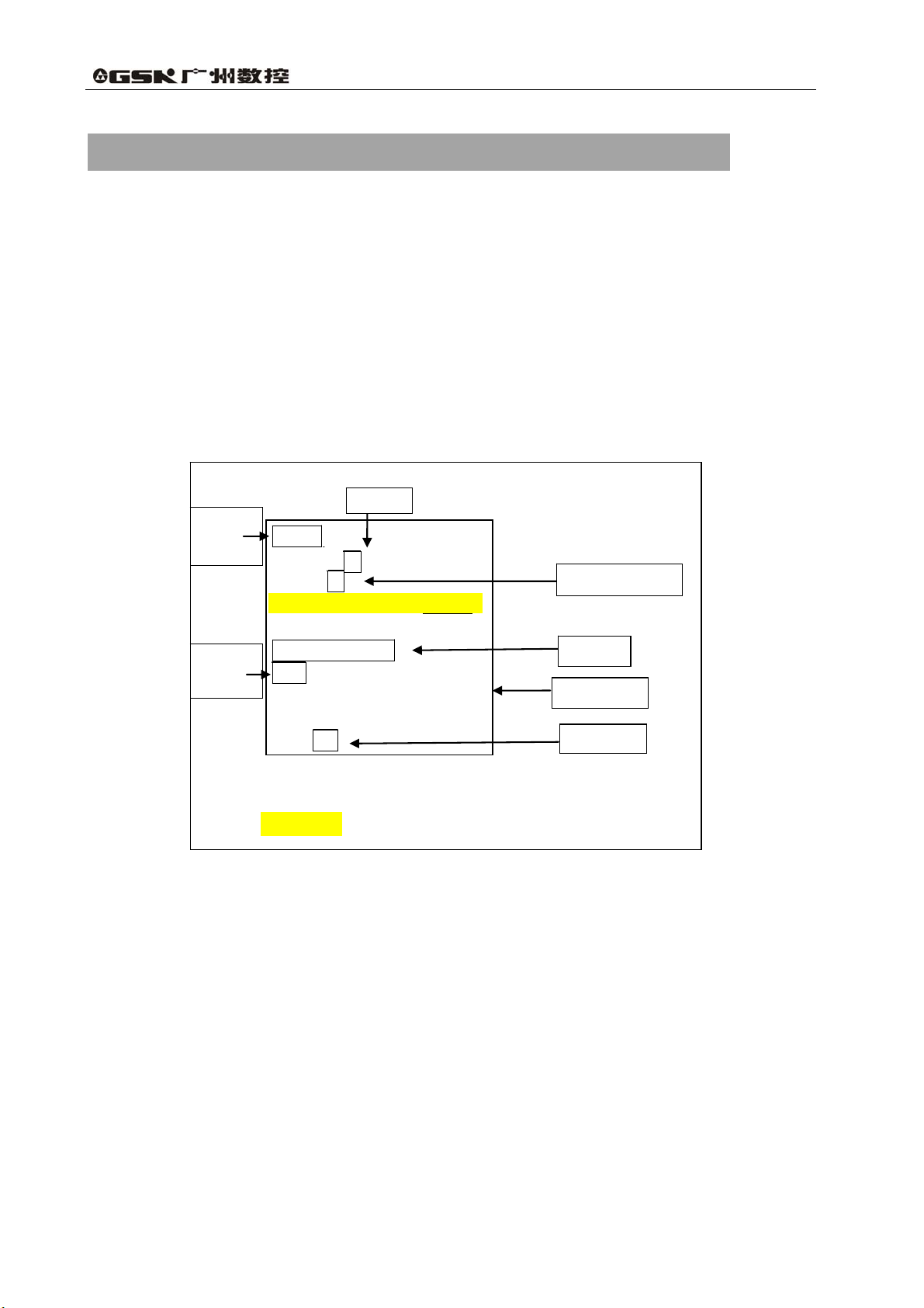
1.2.1 Program Name
This system is able to store several different programs. A program name consisting of the
address O followed by four-digit number is assigned to each program at the beginning to identify
them. Shown in Fig. 1-2.
4
Page 18
Volume I Programming and Operation
Fig. 1-2 Block configuration
1.2.2 Sequence Number and Block
A program consists of several commands. One command unit is called a block (see Fig. 1-1).
One block is separated from another with “; ” as the end of block code. (See Fig. 1-1)
At the head of a block, a sequence number consisting of address N followed by six-digit numbers
can be placed (see Fig. 1-1). The leading zero can be omitted. Sequence number can be specified in
a random order, and any number can be skipped. Sequence number may be specified for all blocks
or only for important blocks of a program. In general, however, it is convenient to assign sequence
numbers in ascending order in phase with the machining steps. (For example, when a new tool is
used by tool replacement and machining proceeds to a new surface with table indexing.)
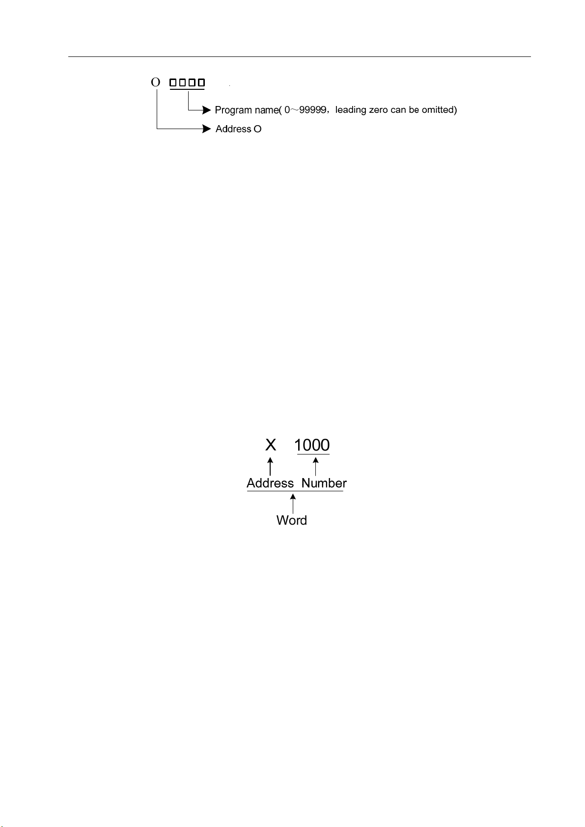
1.2.3 Word
Word is an essential for a block. A word consists of an address followed by a number some digit
long. (The plus sign (+) or minus sign (-) may be prefixed to a number.)
Fig. 1-3 Word configuration
For an address, one of the letters (A to Z) is used. An address defines the meaning of a number
that follows the address. Table1-1 indicates the usable address and their meanings.
The same address may have different meanings, depending on the preparatory function
specification.
5
Page 19

GSK 25i Milling CNC System User Manual
Table 1-1
Address Ranges Function and Meaning
O
N
G
X
Y
Z
R
I
J
K
F
S
T
M
P
Q
H
D
0~99999
0~999999
000~999
-999999.9999~999999.9999(mm)
0~9999.9999(s)
-999999.9999~999999.9999(mm)
-999999.9999~999999.9999(mm)
-999999.9999~999999.9999(mm)
-999999.9999~999999.9999(mm)
-999999.9999~999999.9999(mm)
-999999.9999~999999.9999(mm)
-999999.9999~999999.9999(mm)
0.1~1000000(mm/min)
0.001~10000(mm/r)
0~50000(r/min)
00~06
0~999
00~999
0~9999(s)
1~99999
-999999.999~999999.999(mm)
00~256
00~256
Shift amount of circular radius/angle
X vector between arc center and starting point
Y vector between arc center and starting point
Z vector between arc center and starting point
Miscellaneous function output, program
executed flow, subprogram call
Cutting depth or offset amount for low hole in
Program name
Sequence number
Preparatory function
X-coordinate address
Dwell time
X-coordinate address
X-coordinate address
R surface of canned cycle
Feedrate per minute
Feedrate per revolution
Specifying spindle speed
Multi-gear spindle output
Tool function
Dwell time
Call subprogram number
canned cycle
Length offset number
Radius offset number
Please note that Table 1-1 shows the restriction only for CNC device, the restrictions for machine
tool are not included. Reading this manual as well as the one provided by machine tool builder
before programming enables better understanding to the restriction.
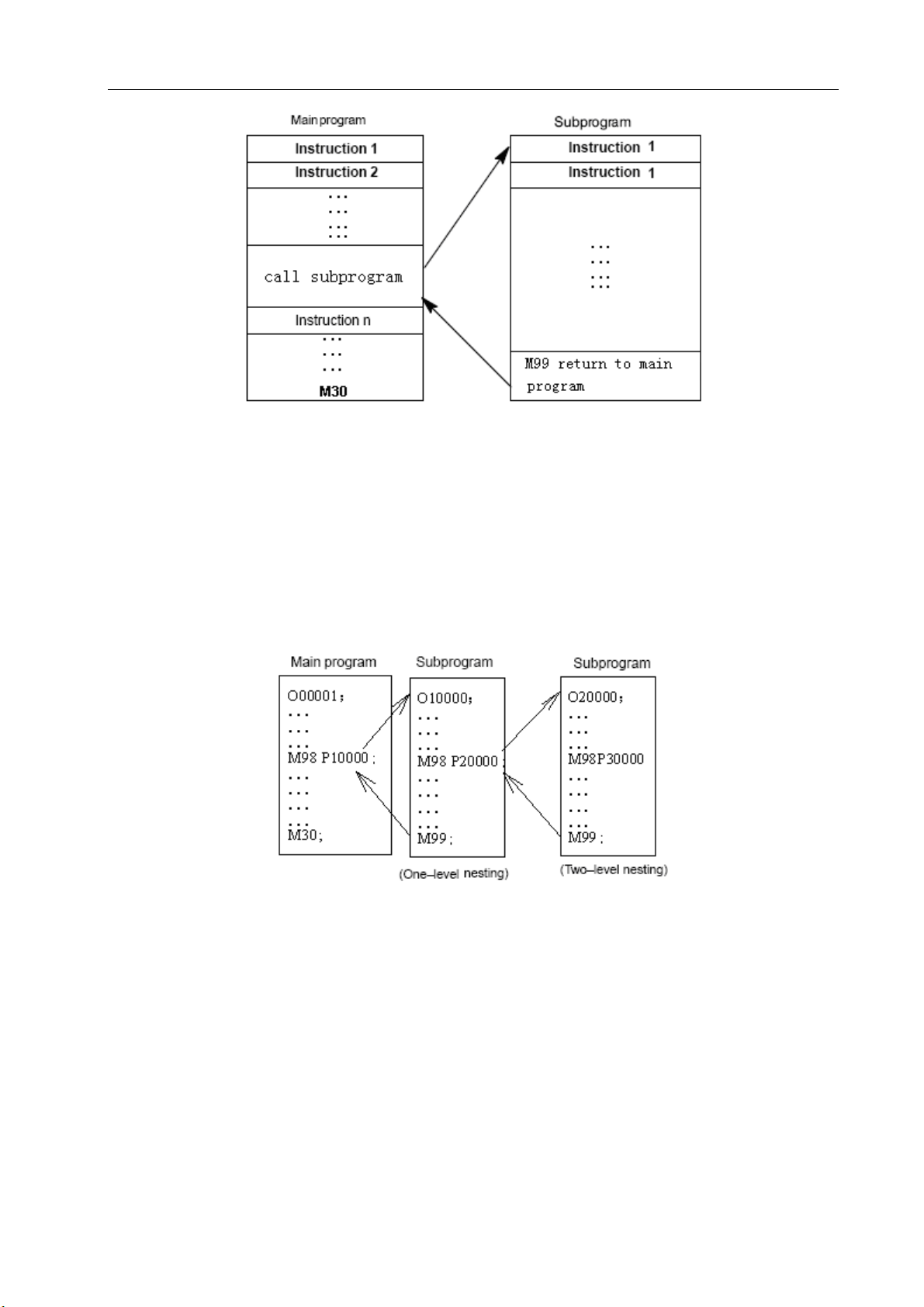
1.3 General Program Structure
A program contains main program and subprogram. Usually, the CNC system performs
according to main program, unless there is a subprogram call in the main program. The main
program will be executed again after a returning command is performed. The sequence is shown in
Fig. 1-4.
6
Page 20
Volume I Programming and Operation
Fig. 1-4 Program run sequence
The structure of a main program is consistent with that of the subprogram.
If a program contains a fixed sequence and frequently repeated pattern, such a sequence or
pattern can be stored as subprogram in memory to simplify the program. A subprogram can be
called in auto mode by command M98. A called subprogram can also call another subprogram. The
subprogram calls can be nested up to four levels (shown in Fig. 1-5). The last block of the main
program should be the return command M99 which enables the next subprogram to be executed.
The program can be repeated when M99 is executed at the end of main program.
Fig. 1-5 Two-level nesting subprogram
A single call command can repetitively and continually call a subprogram up to 999 times.
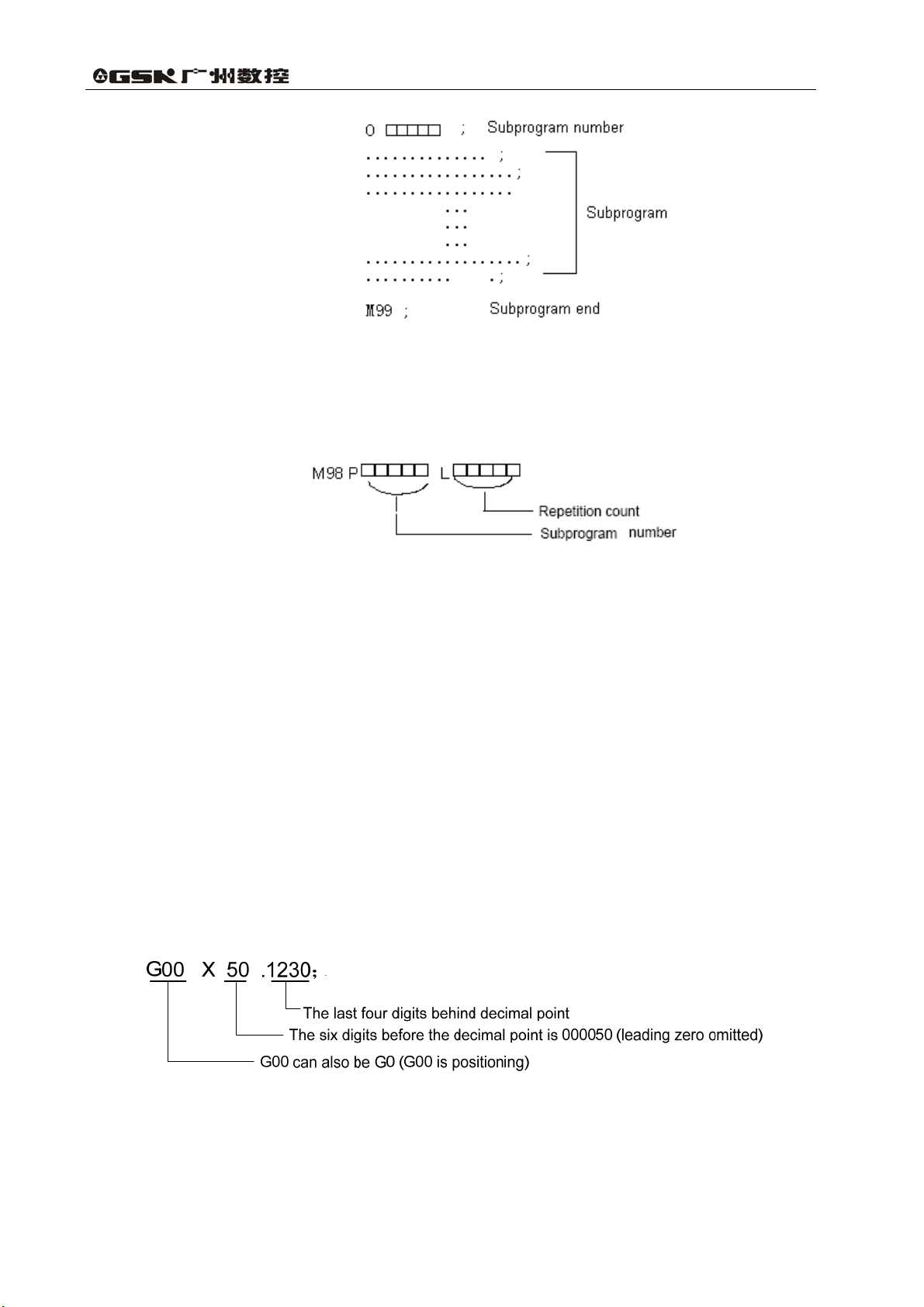
1.3.1 Subprogram Writing and Call
1.3.1.1 Subprogram Writing
Write a subprogram as following format:
7
Page 21
GSK 25i Milling CNC System User Manual
Fig. 1-6
At the beginning of a subprogram, the address O and subprogram number is placed. The end
of the subprogram is command M99 (writing format is shown as above).
A subprogram is called by a call command whose format is shown as follows:
● If the repetition number is omitted, it is assumed to be 1.
(e.g.) M98 P51002 ; (indicates that subprogram number 1002 is called continually 5
times)
●M98 P__ should not coexist with move command in the same block.
●The sequence of subprogram call in a subprogram is the same with that in main program.
Note: CNC enters the alarm state, if a subprogram number specified by address P can not be found.
1.3.2 Program Inputting Format
Words that constitute a block should be input with following format. When the format is
variable, the word quantity in a block and the letter quantity in a word can be changed, it is
convenient for programming.
E.g. with following command, the tool can be positioned to 50.123mm along X axis:
Note: If two commands are assigned by one address in the same block, the later command is valid in
principle. No alarm will occur.
8
Page 22
Volume I Programming and Operation
e.g.:
G00 G01 X100. Y200.;
G01 is valid, G00 is invalid.
1) G code is valid in the last command of the same block.
2) If there are R, I and K codes in the same arc command, R code is valid regardless of the
sequence.
1.3.3 Program End
A Program starts from the program name and ends with command M02, M30 or M99. M02
and M30 enables the system enter into a reset state at the end of a program; the program can be
repeated with command M99; if M99 is executed at the end of a subprogram, system returns to the
program that call the subprogram. By using parameter N0:1803#5 and N0:1803#4 respectively, M30
and M02 determine whether the system returns to the beginning of the program or not.
Warning!
If the optional block skip switch on the machine operation panel is ON, the block with “/” will be
skipped, e.g., command /M02; , /M30; , or /M99; do not indicate the program end.
1.3.4 Optional Block Skip (/)
When a slash followed by a number n(n=1~9) is specified at the head of a block, and optional
block skip switch n on the machine operator panel is set to on, the information contained in the block
for which /n corresponding to switch number n is specified is ignored in DNC operation or memory
operation. When the optional block skip switch n is set to off, the information contained in the block
specified by /n is valid. This means the operator can decide whether to skip blocks contain /n or not.
Number 1 of /1 can be omitted. However, when more than two optional block skip switches are used
in one block, number 1 of /1 cannot be omitted.
Example) (incorrect) (correct)
//3 G00X10.0; /1/3 G00X10.0;
When a program is loaded into memory, this function is ignored. The blocks containing /n are
also stored into memory regardless of how the optional block skip is set. Programs held in memory
can be output regardless of how the optional block skip is set.
The optional block skip is valid even when sequence number is being searched. Different
machine tool has different amount of optional block skip switches (1-9), refer to the manual from
machine tool builder for specific details.
Note:
1. The position of the slash
The slash (/) should be at the head of a block. Otherwise, information between the slash and
9
Page 23

GSK 25i Milling CNC System User Manual
EOB code is ignored.
2. Disabling of optional block skip switch
When a block is read into buffer from memory or tape, the optional block skip operation is
processed. After blocks read into a buffer, the already read blocks are not ignored even if the
optional block skip switch is set to on.
3. TV and TH check
When the optional block skip switch is set to on, the TH and TV check is performed for the
skipped blocks in the same way as when the optional block skip switch is off.
10
Page 24
Volume I Programming and Operation
2 PROGRAMMING FUNDAMENTALS
2.1 Controlled Axes
Table 2-1
Item GSK25i
Number of basic controlled axes
Simultaneously controlled axes(in total
)
5 axes(X,Y,Z,4TH,5TH)
6 axes at most
2.2 Axis Name
The names of 5 basic axes are always X,Y,Z, 4TH,5TH. Parameter No. 9101 sets the number of
controlled axes and NO.1020 assigns name for each.
2.3 Coordinate system
2.3.1 Machine Coordinate System
The point that is specific to a machine and serves as the reference of the machine is referred to
as the machine zero point. A machine tool builder sets a machine zero point for each machine. A
coordinate system with a machine zero point set as its origin is referred to as a machine coordinate
system. A machine coordinate system is set by performing manual reference position return after
power-on. A machine coordinate system, once set, remains unchanged until the power is turned off,
the system is restart or emergency stop is employed.
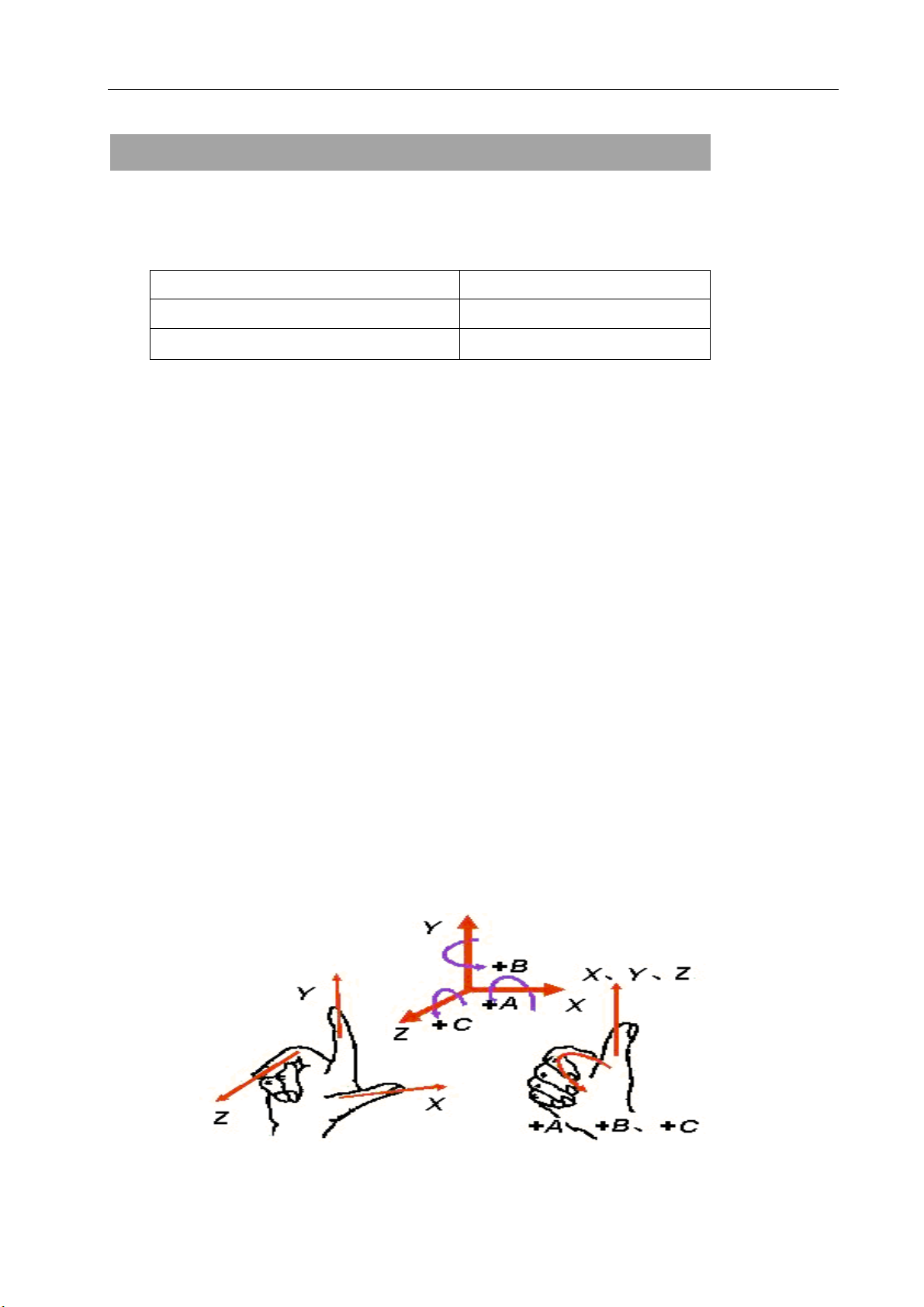
This system adopts right-hand Cartesian coordinate system. The motion along spindle is Z axis
motion. Viewed from spindle, the motion of headstock approaching the workpiece is negative Z axis
motion, and departing for positive. The other directions are determined by right-hand Cartesian
coordinate system.
11
Page 25
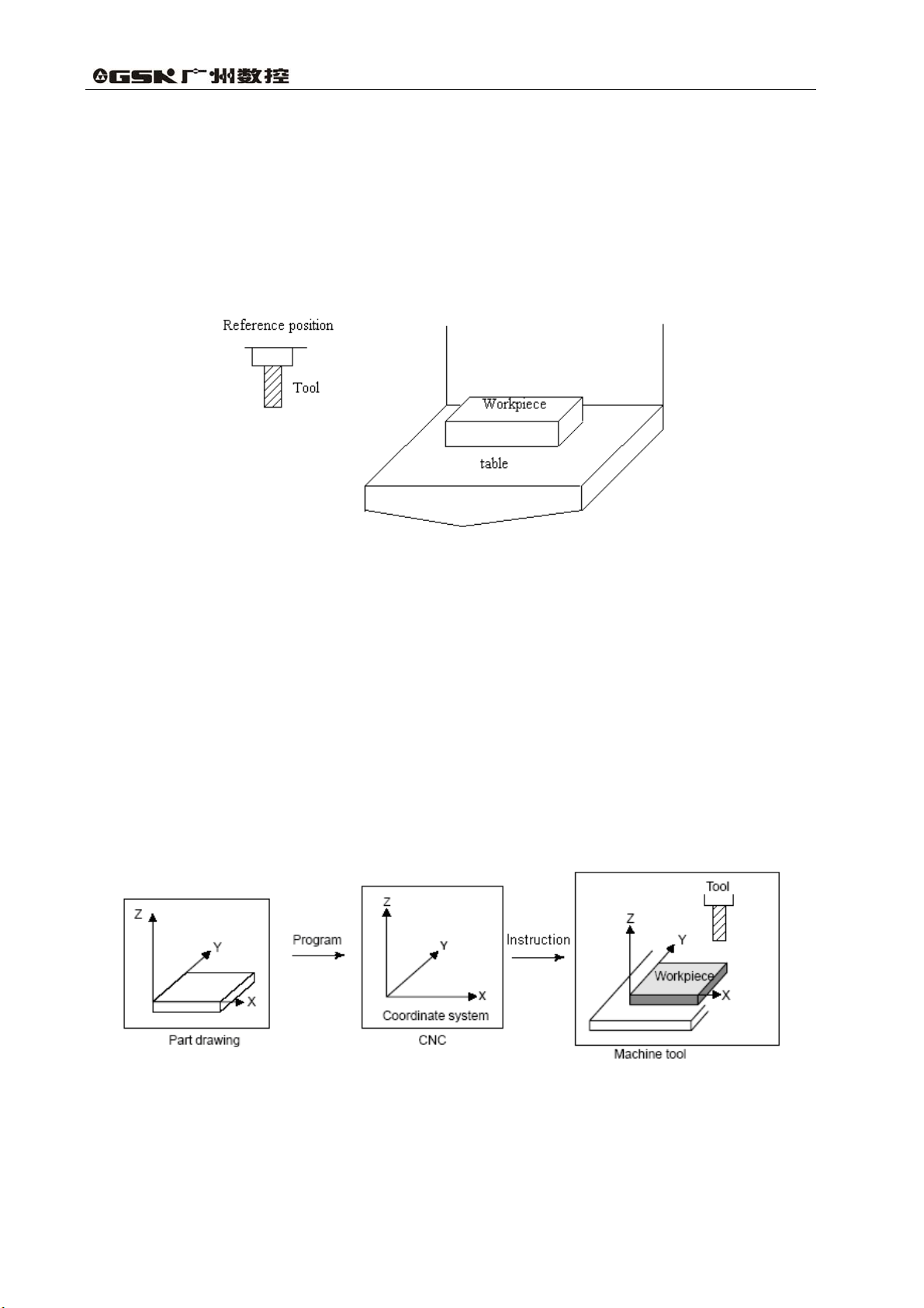
2.3.2 Reference Point
There is a special point on CNC machine tool for tool change and coordinate system
setup, which is called reference point. It is a fixed point in machine coordinate system set by
machine builder. By reference point return, the tool can easily move to this position. Generally
this point in CNC milling system coincides with the machine zero, while the reference point of
Machining Center is usually the tool change point.
GSK 25i Milling CNC System User Manual
Fig.2-1
There are two methods to traverse the tool to reference point:
1. Manual reference point return (see “Manual reference point return” in Operation Manual)
2. Auto reference point return
2.3.3 Workpiece Coordinate System
The coordinate system used for workpiece machining is called workpiece coordinate
system (or part coordinate system), which is preset by CNC system (to set workpiece
coordinate system).
The tool machines workpiece into desired shape on the drawing according to program, so it is
necessary to set relationship between machine coordinate system and workpiece coordinate system.
The method to determine the relationship between these two coordinate systems is called
alignment. It can be done by different methods according to part shape or workpiece quantity.
12
Page 26
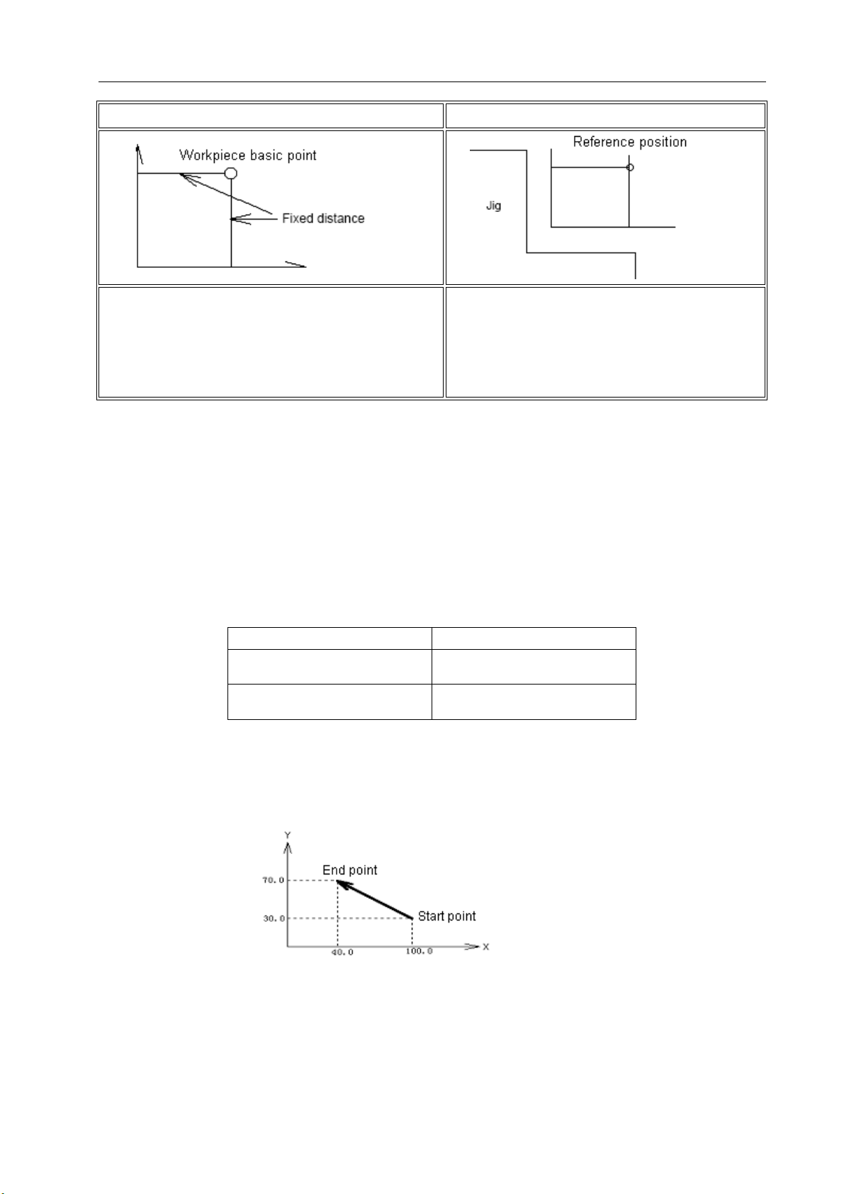
Volume I Programming and Operation
) By Ⅰ workpiece base point ) When part is fixed on jigⅡ
To align the tool center to the workpiece
base point, specify the workpiece coordinate
system by CNC instructions at this position, and the
workpiece coordinate system coincides with the
programming coordinate system.
Workpiece coordinate system can be set by one program and can be altered by moving its origin.
There are two methods to set the workpiece coordinate system:
1. By G92, see 3.2.11 for details.
2. By G54 to G59, see 3.2.8 for details.
Because the tool center can’t be located at
the workpiece base point, locate the tool to a
position (or reference point) that has a distance
to the base point, set the workpiece coordinate
system by this distance(e.g. G92)
2.3.4 Maximum Stroke
Maximum stroke= least command increment×99999999
Table 2-2 Maximum strokes
Increment system Maximum stroke
Metric machine system ±999999.9999mm
±999999.9999degree
Inch machine system ±99999.9999inch
±999999.9999degree
Note:
1.A command exceeding the maximum stroke cannot be specified.
2.The actual stroke depends on the machine tool.
Fig.2-3
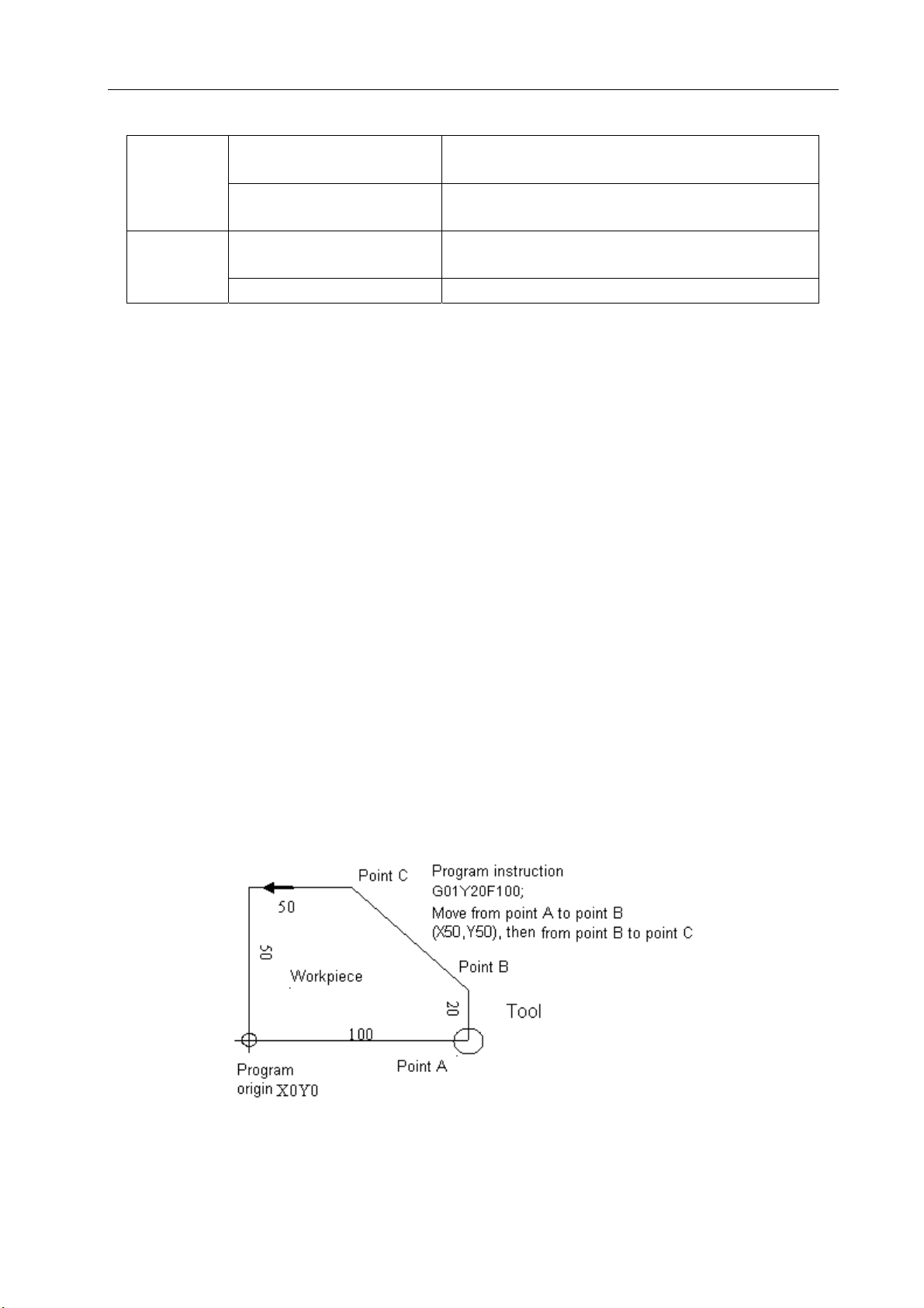
2.3.5 Absolute and Incremental Programming
There are two ways to command travels of the tool: the absolute command and the incremental
command. In the absolute command, coordinate value of the end position is programmed; in the
13
Page 27

GSK 25i Milling CNC System User Manual
incremental command, move distance of the position itself is programmed.
Incremental value command is a method based on the move distance. Regardless of the
coordinate, it just needs the move direction and distance of end position relative to the start position.
G90 and G91 are used to instruct absolute and incremental command.
In Fig. 2-3, moving from the start position to end position involves the following two commands (G90
and G91) respectively:
G90 G0 X40 Y70;
or G91 G0 X-60 Y40 ;
Either of two methods produces the same motion, and is available for operator to select.
Explanation:
¾ G90 and G91 are the modal value of the same group, i.e. G90 mode is defaulted before G91 is
specified; G91 is valid till G90 is specified.
System parameter
Parameter N0:1801#3 determines whether G90 (when parameter is 0) or G91 (when parameter is 1)
is employed as default mode.
2.4 Modal and Non-modal
Modal means that the number followed an address is valid till it is reset. Another function of
modal is that after a word being set, it is not necessary to re-input the word when the same function is
used.
¾ For example:
G0 X100 Y100; (positioning to X100 Y100)
X20 Y30; (positioning to X20 Y30, G0 is modal and can be omitted.)
G1 X50 Y50 F300(linear interpolation to X50 Y50, at a feedrate of 300mm/min G0→G1)
X100; (linear interpolation to X100 Y50, at a feedrate of 300mm/min, G1,Y50 and F300 are
all modal and can be omitted.)
Initial mode is the default mode after power-on. See Table 3-1 for details.
¾ For example:
¾ O00001
¾ X100 Y100; (positioning to X100 Y100, G0 is initial mode)
¾ G1 X0 Y0 F100;(linear interpolation to X0 Y0, at a feedrate of 100mm/min, G98 is initial
mode)
Non-mode means that the numbers after an address is valid in only in the current block
and should be re-specified in next block. As G command of group 00 shown in table 3-1.
Table 2-3 describes the modal and non-modal of commands.
14
Page 28
Volume I Programming and Operation
Table 2-3 modal and non-modal of commands
Modal G function
Modal
Modal M function
Non-modal G function
Non-modal M function Only valid in the current block
G commands are being executed till they are
invalidated by another G commands.
M commands is being executed till they are
invalidated by another M commands.
Only valid in specified blocks and to be cancelled
at the end of a program Non-modal
2.5 Decimal Point Programming
Numerical value can be entered with a decimal point. A decimal point can be used when entering a
distance, time, or speed. Decimal points can be specified with the following addresses:
X, Y, Z, A, B, C, I, J, K, R, P, Q, and F
Explanation:
1. Parameter N0:1800#5 determines the employment of decimal point programming. When
N0:1800#5=1, the unit of programming value is mm, inch or degree; when N0:1800#5=0,
the unit is the least movement unit, determining by parameter N0:1000#1.
2. Fractions less than the least input increment are truncated.
For example:
X9.87654; when the least input increment is 0.001mm, truncated to X 9.876.
when the least input increment is 0.0001mm, processed as X 9.8765.
2.6 Basic Functions
2.6.1 Tool Movement along Workpiece Parts Figure—Interpolation
1)The tool moves along straight lines
15
Page 29
GSK 25i Milling CNC System User Manual
2) The tool moves along arcs
The function of moving the tool along straight lines and arcs is called the interpolation.
Symbols of the programmed commands G01, G02…are called the preparatory function and specify
the type of interpolation conducted in the control unit.
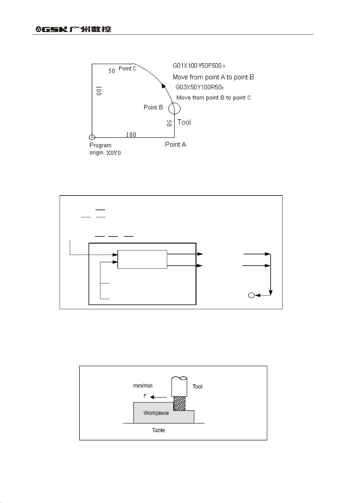
a) Movement along straight line
G01 Y
X Y ;
;
b) Movement along arc
G03 X
Note:
Some machines move tables instead of tools but this manual assumes that tools are
Y R ;
Interpolation
a) Movement along straight line
b) Movement along arc
moved against workpiece. Refer to the actual move direction to avoid danger and damages.
2.6.2 Feed—Feed Function
X axis (Motor)
Y axis (Motor)
Tool movement
The function of specifying a feedrate is called feed function.
Feed is to move the tool with a specified rate. The feedrate is indicated by numeric command. For
example, command F200 means the tool infeeds at a speed of 200mm/min.
16
Page 30
Volume I Programming and Operation
2.6.3 Cutting Speed, Spindle Speed Function
Tool
工 件
Tool diameter
V: Cutting speed
(m/min)
r/min
RPM
workpiece
The speed of the tool with respect to the workpiece when the workpiece is cut is called the
cutting speed. For CNC, it can be specified by the spindle speed RPM(r/min).
For example, when a workpiece is machined with a tool 100mm in diameter at a cutting speed of
80m/min, the spindle speed is about 250r/min, which is obtained from N=1000V/πD. The command is
S250.
Commands related to the spindle speed are called the spindle function.
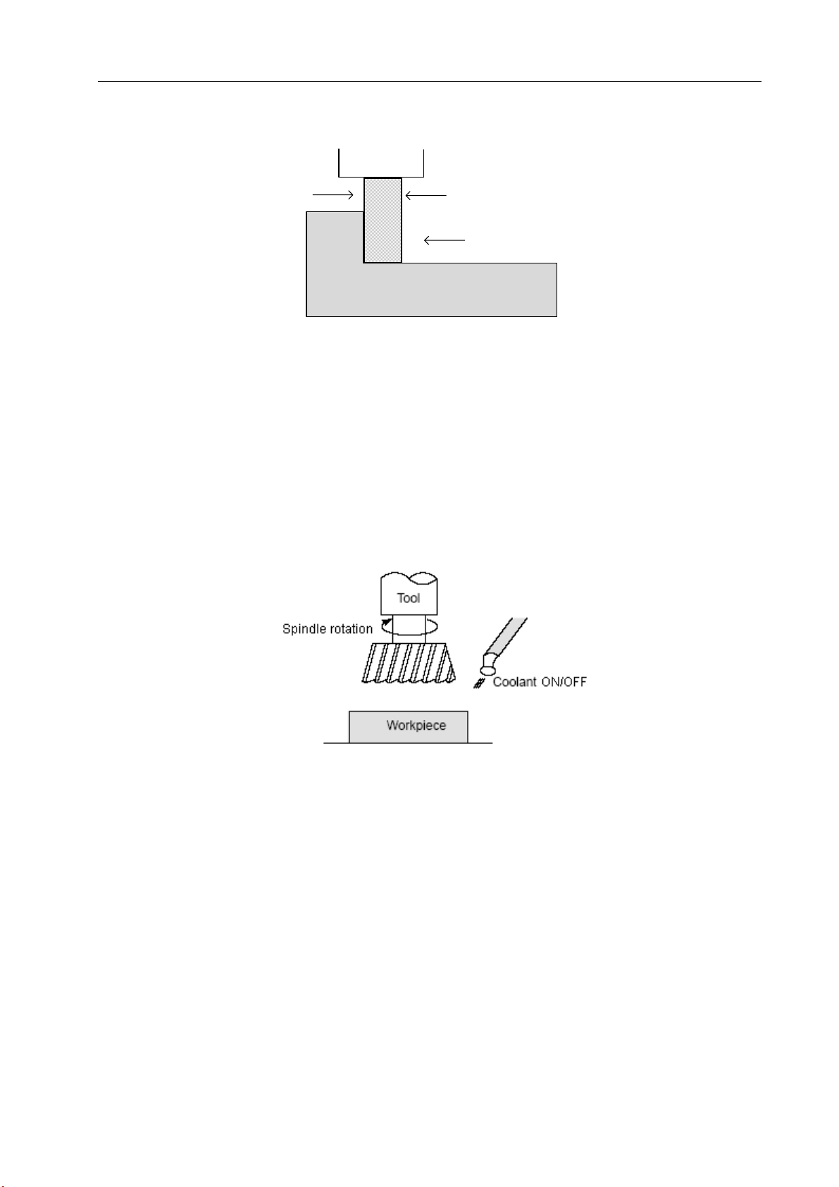
2.6.4 Command for Machine Operations—Miscellaneous Function
When machining is actually started, it’s necessary to rotate the spindle, and feed coolant
accordingly. Thus, the on-off switch for spindle motor and coolant valve should be controlled.
The function of specifying the on-off operations of the machine or program through NC system is
called the miscellaneous function, which is specified by M mode.
For example, when M03 is specified, the spindle rotates clockwise at the specified speed.
(Clockwise means operator views over the spindle along the negative direction of Z axis.)
2.6.5 Selection of Tool Used for Various Machining—Tool
When drilling, tapping, boring, milling or the like, is performed, it is necessary to select a suitable
tool. When a number is assigned to each tool and the number is specified in the program. The
corresponding tool is selected.
17
Page 31

GSK 25i Milling CNC System User Manual
For example, when No. 01 is assigned to a drilling tool
When the tool is stored at location 01 in the ATC magazine, the tool can be selected by
specifying T01. This is called the tool function.
2.6.6 Tool Figure and Tool Motion by Program
2.6.6.1 Tool Length Compensation
Usually, several tools are used for machining one workpiece. When a command is executed,
such as G0Z0, the distance from tools and to workpiece may vary due to different tool lengths.
However, it is very troublesome and error-prone to alter the program frequently.
Therefore, the lengths of tools are measured in advance, and their differences from that of the
standard tool (usually is the first tool) are input into CNC. In this way, machining can be done
without altering the program when tool is changed. The distance from tool end to the workpiece
remains unchanged after Z axis positioning (such as G0Z0) is executed. This function is called tool
length compensation function.
18
Page 32

2.6.6.2 Cutter Compensation Function
Volume I Programming and Operation
Tool path using tool radius compensation
Workpiece
Machined part figure
Tool
Because a tool has a radius, a workpiece will be overcut a cutter radius if the programmed path
is followed. To simplify programming, the program can be run with a cutter radius deviated around the
machined part figure. The path of intersection between lines and arcs is processed by system
automatically.
Cutter diameters should be stored in the compensation list in advance, so that the cutter path may
vary with different cutter compensation values. This function is called cutter compensation function.
2.6.6.3 Tool Movement Range—Stroke
A safe movement range can be set by parameters. Exceeding of the range leads to motion stop
of all axes and an alarm will be issued in that case. This function is called stroke check, usually called
soft restriction.
19
Page 33

GSK 25i Milling CNC System User Manual
3 PREPARATORY FUNCTION G CODES
3.1 Types of G Codes
The number following address G determines the meaning of the command for the concerned
block. G codes are divided into the following two types.
Table 3-1 types of G codes
Type meaning
Non-modal G code
Modal G code
(Example) G01 and G00 are modal G codes in group 01.
G01 X _ ;
Z ___ ; G01 is effective
X ___ ; G01 is effective
G00 Z__; G00 is effective
Table 3-2 G codes List
G code Group Commands format Functions
*G00 G00 X_Y_Z_ Positioning (rapid traverse)
G01 G01 X_Y_Z_F_ Linear interpolation (cutting feed)
G02 Circular interpolation (CW)
G03
G04 00
01
G02 R_
G03
X_Y_
I_J_
G04 P_ or G04 X_
The G code is effective only in the
block in which is specified
The G code is effective until another G
code of the same group is specified.
F_;
Circular interpolation (CCW)
Dwell, Exact stop
G10 00 G10L_; N_P_R_ Programmable data input
*G11 00
*G15 G15 Polar coordinate command cancel
G16
*G17
G18
G19
G20 Input in inch
*G21
G27
G28 G28 Return to reference point
G29 G29 Return from the reference point
G30 G30Pn 2nd, 3rd,and 4th reference point return
G31 G31
G39
17
02
06
00
G11
G16
write followed other words and used
in circular interpolation and cutter
radius compensation
Input at the beginning of a block and
before the coordinate system is set.
Specified by an independent block.
G27
X_Y_Z_
G39 I_J_; I_J_; J_K_or
G39
Programmable data input mode cancel
Polar coordinate command
XY plane selection
ZX plane selection
YZ plane selection
Input in metric
Reference point return check
Skip function
Corner offset circular interpolation
20
Page 34

Volume I Programming and Operation
*G40 G17 X_Y_ Cutter compensation cancel
G41 G18 X_Z_ Cutter compensation left
G42
G43 G43 Tool length compensation + direction
G44 G44 Tool length compensation - direction
*G49
*G50 G51 Scaling cancel
G51
G53 00 Write in a program Machine coordinate system selection
*G54 Workpiece coordinate system 1
G55 Workpiece coordinate system 2
G56 Workpiece coordinate system 3
G57 Workpiece coordinate system 4
G58 Workpiece coordinate system 5
G59
G60 00
G61 G61 Exact stop mode
G62 G62 Automatic corner override
G63
07
08
11
14
15
G19
G49
G51 X_ Y_ Z_ P_ Scaling
Write together with others, usually it
is placed at the beginning of a
G60 X_ Y_ Z_ F_
G40
G41
G42
program.
G63
Y_Z_ Cutter compensation right
Z_
Tool length compensation cancel
Workpiece coordinate system 6
Single direction positioning
Tapping mode
*G64
G65 00 G65 H_P# i Q# j R# k Macro program command
G68 G68 X_ Y_ R_ Coordinate rotation
*G69
G73 G73 X_Y_Z_R_Q_F_; Peck drilling cycle
G74 G74 X_Y_Z_R_P_F_; Counter tapping cycle
G76 G76 X_Y_Z_R_P_F_K_; Fine boring cycle
*G80 Write together with others Canned cycle cancel
G81 G81 X_Y_Z_R_F_; Drilling cycle (spot drilling cycle)
G82 G82 X_Y_Z_R_P_F_; Drilling cycle (stepped hole boring cycle)
G83 G83 X_Y_Z_R_Q_F; Peck drilling cycle
G84 G84 X_Y_Z_R_P_F_; Tapping cycle
G85 G85 X_Y_Z_R_F_; Boring cycle
G86 G86 X_Y_Z_R_F_; Drilling cycle
G8
7
G8
8
G89
*G90 Absolute programming
G91
G92 00 G92 X_Y_Z_ Workpiece coordinate system preset
*G94
16
G69 Coordinate rotation cancel
09
G87 X_Y_Z_R_Q_P_F_;
G88 X_Y_Z_R_P_F_;
G89 X_Y_Z_R_P_F_; Boring cycle
03 Write together with others
05
G64 Cutting mode
Counter boring cycle
Boring cycle
Incremental programming
G94
Feed per minute
21
Page 35

GSK 25i Milling CNC System User Manual
G95 G95 Feed per rotation
G96 G96S_ Constant surface speed control
*G97
13
G97S_
Constant surface speed control cancel
*G98 Return to initial plane in canned cycle
G99
G110
G111
10 Write together with others
X_ Y_ R_ Z_ I_ L_ W_ Q_ V_ D_ F_
K_
X_ Y_ R_ Z_ I_ L_ W_ Q_ V_ D_ F_
K_
Return to R point in canned cycle
Circular groove inner rough milling
(CCW)
Circular grove inner rough milling
(CW)
G112 X_Y_ R_ Z_ I_ J_ D_ F_ K_ Circular inner finish milling cycle (CCW)
G113 X_Y_ R_ Z_ I_ J_ D_ F_ K_ Circular inner finish milling cycle (CW)
G114 X_Y_R_Z_I_J_L_W_Q_V_D_F_K_ Circular outer rough milling cycle (CCW)
G115 X_Y_R_Z_I_J_L_W_Q_V_D_F_K_ Circular outer rough milling cycle (CW)
G116
X_Y_ R_ Z_ I_ J_D_F_ K_ Circular outer finish milling cycle
(CCW)
G117 X_Y_ R_ Z_ I_ J_D_F_ K_ Circular outer finish milling cycle (CW)
G130
G131
G132
G133
G134
G135
G136
G137
09
X_Y_Z_R_I_J_L_W_Q_V_U_D_F_
K_
X_Y_Z_R_I_J_L_W_Q_V_U_D_F_
K_
X_ Y_ R_ Z_ I_ J_ D_ L_ U_ F_ K_ Rectangular groove inner finish milling
X_ Y_ R_ Z_ I_ J_ D_ L_ U_ F_ K_ Rectangular groove inner finish milling
X_Y_Z_R_I_J_L_W_Q_V_E_U_D_
F_K
X_Y_Z_R_I_J_L_W_Q_V_E_U_D_
F_K
X_Y_R_Z_I_J_D_L_U_F_K_ Rectangular outer finish milling cycle
X_Y_R_Z_I_J_D_L_U_F_K_ Rectangular outer finish milling cycle
Rectangular groove rough milling
(CCW)
Rectangular groove rough milling
(CW)
cycle (CCW)
cycle (CW)
Rectangular groove outer rough milling
(CCW)
Rectangular groove outer rough milling
(CW)
(CCW)
(CW)
G120 X_Y_I_J_K_ Bolt hole circle (Canned Cycle)
G121 X_Y_I_J_K_ Line at angle (Canned Cycle)
G122 X_Y_I_J_P_K_ Arc (Canned Cycle)
G123 X_Y_I_P_J_K_ Grid (Canned Cycle)
00
G124 X_Y_R_Z_I_J_P_K_F_ Rectangular drilling (CW)
G125 X_Y_R_Z_I_J_P_K_F_ Rectangular drilling (CCW)
G126 X_Y_Z_I_J_L_F_ Round trip milling
G127
X_Y_Z_I_J_L_F_ Single trip milling
Note:
1.The G codes with mark * are the default G codes at power-on state.
2.G codes in 00 group are non-modal G codes except for G10 and G11.
3.If a G code not presented in G code list is used, or a G code has no corresponding function is
22
Page 36

Volume I Programming and Operation
specified, an alarm is output.
4.Multiple G codes can be specified in the same block if each G code belongs to a different group. If
multiple G codes that belong to the same group are specified in the same block, only the last G code
specified is valid.
5.If a G code belonging to group 01 is specified in a canned cycle, the canned cycle is cancelled and
G80 is set. However, the G codes in group 01 are not affected by a G code specifying a canned cycle.
6.G codes are indicated by group according to their types.
3.2 Simple G Code
3.2.1 Positioning (G00)
Function :The G00 command moves a tool to the position in the workpiece system specified with
an absolute or an incremental command at a rapid traverse rate.
Format: G00 IP_
IP_:For absolute command, the coordinate of an end position, and for an incremental
command, the distance the tool moves.
Either of the following tool paths can be selected according to N0:1200#1 (see Fig. 3-1)
1.Linear interpolation positioning: the tool path is the same as in linear interpolation (G01). The
tool is positioned within the shortest possible time at a speed that is not more than the rapid
traverse rate for each axis.
2.Non-linear interpolation positioning: the tool is positioned with the rapid traverse rate for each
axis separately. The tool path is normally not straight.
Fig. 3-1
Explanation:
1. G00 rapid traverse rate is set by parameter P1126, and the current tool move mode is
changed into G00 mode. By changing parameter P1801#0, the default mode after power-on can be
set as G00 (parameter value is 0)
2. The tool does not move until a positioning parameter is specified. The system only
changes tool move mode for G00.
3. G00 is identical with G0.
or G01 (parameter value is 0).
23
Page 37

GSK 25i Milling CNC System User Manual
Restriction:
1.The rapid traverse rate cannot be specified in the address F. If a feedrate is specified in G0
command, it is used as the cutting feedrate that followed. For example:
G0 X0 Y10 F800; Feeding at a rate set by system parameter
G1 X20 Y50; at the rate set by F800
The following keys on the operation panel are used to adjust rapid feedrate, see Fig 3-2, involving
such overrides as F0, 25, 50, 100%; The feedrate corresponding to F0 is set by parameter
P1231, and it applies to all axes.
Fig.3-2 Rapid feedrate keys
3.2.2 Linear Interpolation G01
Function: Tool moves linearly to a specified position at the feedrate set by F.
Format : G01 IP_ F_
IP_:For absolute command, the coordinate of an end position, and for an incremental
command, the distance the tool moves.
F_:Speed of tool feed (feedrate)
Explanation :
The feedrate should be specified in F and it is effective until a new value is specified. The
feedrate commanded by the F code is measured along the linear interpolation path. If the F code is
not commanded, the feedrate is regarded as zero.
Example (see Fig. 3-3)
Feedrate of X axis direction
G01 X200 Y100 F200 ;
Note: the feedrate of each axis direction
is as follows:
G01 Xα Yβ ZγFf ;
Feedrate of Y axis direction
222
γβα
++=L
Fig. 3-3
Feedrate of Z axis direction
24
Page 38

Volume I Programming and Operation
Note:
1.The ceiling limits of cutting feedrate F for each axis can be set by parameter P1125. If the actual
cutting feedrate (feedrate after override is used) exceeds the ceiling limit, the later will be adopted as
feedrate (Unit mm/min). The ceiling limit of multi-axes resultant cutting feedrate can be set by
parameter P1124. If the actual cutting feedrate (feedrate after override is used) exceeds the ceiling
limit, the later will be adopted as feedrate (Unit mm/min).
2. The tool does not move when a position parameter followed G01 is not specified, and the current
tool move mode is changed into G00 mode. By changing parameter P1801#0, the default mode after
power-on can be set as G00 (parameter value is 0) or G01 (parameter value is 0).
3.When the linear interpolation (rotation axes A,B or C) involves over 4-axes, the unit of cutting
feedrate changes from degree to inch (or mm), and the cutting feedrate in Cartesian coordinate
system is set to be equal to the feedrate specified by F code. The feedrate of rotation axes is
calculated by the formula in Fig. 3-3, the unit changed into deg./min.
Example: G91 G01 B90.0 F300;
Example: G91 G01 X20.0 B40.0 F300.0;
When the unit of cutting feedrate of B axis changed from degree to mm or inch, the calculation
formula of processing time is as follows:
22
+
4020
300
The feedrate of B axis is:
40
14907.0
=
=
0.014907
(min)
268.3
(deg/ min)
3.2.3 Circular Interpolation (Helical Interpolation) G02/G03
3.2.3.1 Circular Interpolation G02/G03
Format:The command below will move a tool along a circular arc.
Arc in the X—Y plane
25
Page 39

GSK 25i Milling CNC System User Manual
G02 R——
G17 X——Y—— F——;
G03 I——J——
Arc in the Z——X plane
G02 R——
G18 X——Z—— F——;
G03 I——K——
Arc in the Y——Z plane
G02 R——
G19 Y——Z—— F——;
G03 J——K——
Item Command Description
G17 Arc on plane XY
1 Plane selection
2 Rotation direction
G90 mode
G91 mode
3
End
point
Distance from start point
4
to end point
Arc radius R Arc radius
As an initial code, G17 is effective after power-on.
Explanation:
“Clockwise” (G02) and “counterclockwise”(G03)on the XY plane (ZPXP plane or YPZP plane)
are defined when the XY plane is viewed in the positive-to negative direction of ZP axis (ZP axis or
XP axis respectively) in the Cartesian coordinate system. See the figure below.
G18 Arc on plane ZX
G19 Arc on plane YZ
G02 CW
G03 CCW
2 axes of X, Y, Z
axes
2 axes of X, Y, Z
End point of workpiece coordinate
system
Distance from start point to end point
axes
2 axes of I, J, K
Distance from start point to end point
The end point of an arc is specified by address ZP, YP or ZP, and is expressed as an absolute or
incremental value according to G90 or G91. For the incremental value, the distance of the end point
which is viewed from the start point of the arc is specified.
26
Page 40

Volume I Programming and Operation
The arc center is specified by address I,J and K for the XP, YP, and ZP axes, respectively. The
numerical value following I,J, or K, however, is a vector component in which the arc center is seen
from the start point, and is always specified as an incremental value irrespective of G90 and G91, as
shown below.
I,J and K must be signed according to the direction (positive or negative).
End p o int (X,Y)
End point (Z,X)
End point (Y,Z)
Start point
K
Center
Start p o in tStart point
J
I
Center
K
I
Center
J
I0, J0 and K0 can be omitted. When XP, YP AND ZP are omitted (the end point is the same as
the start point) and the center is specified with I,J and K, a 360°arc (circle) is specified.
G02 I_; command for a circle.
If the difference between the radius at the start point and that at the end point exceeds the
permitted value in a parameter P1810, and alarm occurs.
The distance between an arc and the center of a circle that contains the arc can be specified
using the radius, R of the circle instead of I, J and K. In this case, one arc is less than 180°, and the
other is more than 180° are considered. When an arc exceeding 180° is commanded, the radius
must be specified with a negative value. If XP, YP and ZP are all omitted, if the end point is located
at the same position as the start point and when R is used, an arc of 0° is programmed.
G02 R; (the cutter does not move)
Example:
1. For arc less than 180°
G02 X6.0 Y2.0 R5.0;
2. For arc more than 180°
G02 X6.0 Y2.0 R-5.0;
27
Page 41

GSK 25i Milling CNC System User Manual
a)Absolute programming
(I) G92 X200.0 Y40.0 Z0;
(II) G90 G03 X140.0 Y100.0 I-60.0 F300.0;
(III) G02 X120.0 Y60.0 I-50.0;
(IV) G92 X200.0 Y40.0 Z0;
(V) G90 G03 X140.0 Y100.0 R60.0 F300;
(VI) G01 X120.0 Y60.0 R50.0;
b)Incremental programming
(I) G91 G03 X-60.0 Y60.0 I-60.0 F300;
(VII) G02 X-20.0 Y-40.0 I-50.0;
(II) G91 G03 X-60.0 Y60.0 R60.0 F300;
(VIII) G02 X-20.0 Y-40.0 R50.0;
The feedrate in circular interpolation is equal to the feedrate specified by the F code, and the
feedrate along the arc (the tangential feedrate of the arc) is controlled to be the specified feedrate
is±2% or less. However, this feedrate is measured along the arc after the cutter compensation is
applied.
If I,J and R addresses are specified simultaneously, the arc specified by address R takes
precedence and the other are ignored.
When an arc having a center angle approaching 180° is specified, the calculated center
coordinates may contain an error. In such a case, specify the center of the arc with I, J and K.
28
Page 42

Volume I Programming and Operation
3.2.3.2 Helical Interpolation G02/G03
Format:G02/G03
Function: Helical interpolation which moved helically is enabled by specifying up to two other axes
which move synchronously with the circular interpolation by circular commands.
Explanations:
Z
Tool path
X
Th e feed ra te alo ng th e circ um fere nc e o f tw o
circular interpolated axes is the specified feedrate
Y
The command method is to simply or secondary add a move command axis which is not circular
interpolation axes. An F command specifies a feedrate along arc. Therefore, the feedrate of the linear
axis is as follows:
axislinear oflength
F×
arccircular oflength
Determine the feedrate so the linear axis feedrate does not exceed any of the various limit
values.
Restrictions: Cutter compensation is applied only for a circular arc
Tool offset and tool length compensation cannot be used in a block in which a helical interpolation is
commanded.
29
Page 43

GSK 25i Milling CNC System User Manual
3.2.4 Cylindrical Interpolation (G07.1)
The amount of travel of a rotary axis specified by an angle is once converted into a distance of a
linear axis along the outer surface so that linear interpolation or circular interpolation can be
performed with another axis. After interpolation, such a distance is converted back into the amount of
travel of a rotary axis.
Cylindrical interpolation allows the cylinder flank to be developed for programming. So
programs such as a cylindrical cam grooving program can be easily created.
Format:
G07.1 IP1: Starts the cylindrical interpolation mode
(enables cylindrical interpolation)
…
G07.1 IP0: The cylindrical interpolation mode is cancelled.
IP: An address for the rotation axis
r: The radius of the cylinder
Specify G07.1 IPr: and G07.1 IP0: in separate blocks,
G107 can be used instead of G07.1.
Explanation:
1) Plane selection (G17, G18, G19)
Use parameter No. 1024 to specify whether the rotary axis is X axis, Y axis, Z axis or an axis
parallel to one of these axes. Specify the G code to select a plane for which the rotary axis is the
specified linear axis.
For example, when the rotary axis is an axis parallel to the X axis, G17 must specify and Xp-Yp
plane, which is a plane defined by the rotary axis and the Y axis or an axis parallel to the Y axis. Only
one rotary axis can be set for cylindrical interpolation.
2) Feedrate
A feedrate specified in the cylindrical interpolation mode is a speed on the developed cylindrical
surface.
3) Circular interpolation
In the cylindrical interpolation mode, circular interpolation can be performed between the rotary
axis and another linear axis. Radius R is used in commands in the same way as circular interpolation.
The unit for a radius is not degrees but mm (for metric input) or inch (for inch input)
Example: for circular interpolation between the Z axis and C axis, 5 is to be set (axis parallel to X axis)
for the C axis of parameter No.1024, the command is:
G18 Z_C_;
G02(G03) Z_C_R_;
6 (axis parallel to Y axis) can be specified instead for the C axis of parameter No.1021, the command
is:
G19 C_Z_;
G02(G03) Z_C_R_;
4) Cutter compensation
To execute cutter compensation in cylindrical interpolation mode, an ongoing cutter
compensation should be cancelled before entering into cylindrical interpolation mode, then a cutter
30
Page 44

Volume I Programming and Operation
compensation can be started and terminated within the cylindrical interpolation mode.
5) Cylindrical interpolation accuracy
In the cylindrical interpolation mode, the amount of travel of a rotary axis specified by an angle is
internally converted to a distance of a linear axis on the outer surface so that linear interpolation or
circular interpolation can be performed with another axis. After interpolation, such a distance is
converted back to an angle. For this conversion, the amount of travel is rounded to a least input
increment. Therefore, when the radius of a cylinder is small, the actual amount of travel can differ
from a specified amount of travel. Note, however, that such an error is not accumulative. If manual
operation is performed in the cylindrical interpolation mode with manual absolute on, an error can
occur for the reason described above.
The actual amount of travel=
MOTION REV: The amount of travel per rotation of the rotary axis (360°).
Limitations:
1) Specify arc radius in cylindrical interpolation mode
Address I, J or K cannot be used to specify the arc radius in cylindrical interpolation mode.
2) Circular interpolation and cutter compensation
If the cylindrical interpolation mode is started when the cutter compensation is already applied, even
circular interpolation cannot be performed correctly in such case.
3) Positioning
In cylindrical interpolation mode, positioning cannot be specified (including cycles that generate rapid
traverse, such as G28, G53, G73, G74, G76, G89~G89). Cylindrical interpolation mode should be
cancelled before positioning. Cylindrical interpolation (G07.0) cannot be executed in positioning
mode (G00).
4) Coordinate system setting
In cylindrical interpolation mode, workpiece coordinate system (G92, G54~G59) and local
coordinate system (G52) cannot be specified.
5) Cylindrical interpolation mode setting
In the cylindrical interpolation mode, the cylindrical interpolation mode cannot be reset. The
cylindrical interpolation mode should be cancelled before resetting the cylindrical interpolation.
6) Tool offset
Tool offset should be specified prior to cylindrical interpolation mode setting. Besides, it cannot be
changed in cylindrical interpolation mode.
7) Index table indexing function
Cylindrical interpolation cannot be specified when index table indexing function is being used.
Example of a Cylindrical Interpolation Program
⎡
⎢
⎣
MOTION π
REV
×
R
22
π
⎡
⎢
⎣
××
valueSpecified
×
22
R
REV
MOTION
⎤
⎤
⎥
⎥
⎦
⎦
31
Page 45

GSK 25i Milling CNC System User Manual
3.2.5 NURBS Interpolation
In the CAD drawings for mould designs such as car and plane, NURBS (Non Uniform Rational
B-Spline) is widely used as a method to describe sculptured surfaces and curves of the metal dies.
The NURBS interpolation can directly specify the expression of NURBS curves to CNC device. This
eliminates the need for approximating the NURBS curve with minute line segments, which brings the
following advantages:
1. Eliminate the errors due to linear approximation of designed NURBS curves.
2. Shorten the part programs
3. Avoid the “break” between blocks during the execution of small blocks at high-speed.
4. There is no need to perform high-speed transfer from the main unit to the CNC.
32
Page 46

Volume I Programming and Operation
Based on the NURBS expression output by CAD, the NURBS interpolation function creates NURBS
curves after compensating for the tool holder length, tool diameter and other tool elements. The
NURBS curve is programmed by using 3 parameters: control point, weight, knot.
CAD(Designing a metal die)
Generating a metal die surface
(NURBS surface or curve)
CAM(Creating an NC part program)
Studying the machining
method and others
Tool compensation file
NC part program after tool compensation
(NURBS curve)
NURBS curve (control point weight knot)
CNC epuipment Machine tool
NC part program for mould machining based on NURBS curve command
NURBS interpolation should be specified in high-precision contouring control mode (between G05
P10000~G05 P0). The NURBS interpolation is executed while the acceleration/deceleration of all
axes is controlled within the permitted range to prevent collision.
Format:
G05 P10000; (High precision contour control mode ON)
…
G06.2 [P_]K_X_Y_Z_[R][F];
K_X_Y_Z_[R];
K_X_Y_Z_[R];
K_X_Y_Z_[R];
...
K_;
G01...
...
G05 P0; High precision contour control mode OFF
G06.2: NURBS interpolation mode
P_: The rank of NURBS curve
X_Y_Z_: Control point
R_: Weight
K_: Knot
F_: Feedrate
33
Page 47

GSK 25i Milling CNC System User Manual
{
Note:
1. NURBS interpolation mode
NURBS interpolation mode is selected when G06.2 is programmed. G06.2 is the modal G code in
01 group. Therefore, specifying the G codes in 01 group other than G06.2 (such as G00, G01, G02,
G03) can end the NURBS interpolation. NURBS interpolation should be completed before the
high-precision contouring control mode is OFF.
2. NURBS rank
A rank of NURBS can be specified by address P. the rank setting, if any, must be specified in the
first block. If the rank setting is omitted, a rank of four (degree of three) is assumed for NURBS. The
valid data range for P is 2-4. the P value have the following meanings:
P2 : NURBS having a rank of two (degree of one)
P3 : NURBS having a rank of three (degree of two)
P4 : NURBS having a rank of four (degree of three) (default value)
The rank referred here is the “k” in the definition expression of NURBS curve described latter. For
example, the rank having a rank of four has a degree of three.
3. Weight
The weight of a control point programmed in a single block can be defined. When the weight
setting is omitted, the weight value is assumed to be 1.0.
4. Knot
The number of specified knots equals the number of control points plus the rank value. In the
blocks specifying the first to last control points, each control point and a knot are specified in an
identical block. After these blocks, as many blocks (including only a knot) as the rank value are
specified. The NURBS curve programmed for NURBS interpolation must start from the first control
point and end at the last control point. The first k knots (where k is the rank) must have the same
values as the last k knots (multiple knots). If the absolute coordinate of the start point of NURBS
interpolation do not match the position of the first control point, P/S alarm is issued. (To specify
incremental values, G06.2 X0 Y0 Z0 K_ must be programmed).
5. NUBRS curve
Describe every variable in following formats:
k : rank
Pi : control point
Wi : weight
Xi : knot (Xi ≤ Xi+1)
Knot vector [X0, X1,..., Xm] (m = n+ k)
t : spline parameter
Spline basis function N based on de Boor-Cox recursive formula can be expressed as
follows:
34
)1xt1(x
<<
1ii
(t)N
−
=
(t))N(t-x
1
i,k-i
+
xx
ik-i
=
(t)N
i,k
1
+
+
t)x,x0(tli,
<<
1ii
+
(t)-t)N(x
11
++
,k-iki
−
xx
++
iki
1
Page 48

Volume I Programming and Operation
The NURBS curve P (t) of interpolation can be expressed as follows:
m
)(
∑
P(t)≤≤=
6. Reset
Resetting in the process of NURBS interpolation results in the clear state, meanwhile the
NURBS interpolation mode is cancelled.
Limitations
1. Controlled axes
Up to 3 axes can perform NURBS interpolation. All the axes that perform NURBS interpolation
should be specified in the first block (G06.2 block). When there is no command in the first block, the
axes should be specified in the second block, otherwise, program error occurs and an alarm is
issued.
2. Commands in NURBS interpolation mode
In NURBS interpolation mode, the G codes, feedrate, MSTB codes and other interpolation mode
cannot be specified.
3. Manual intervention
When manual intervention is performed in manual absolute mode, P/S alarm is generated.
4. Cutter compensation
It cannot be used together with the cutter compensation. Please cancel the cutter compensation
before specifying NURBS interpolation.
5. Control point
As the first control point (coordinate value of G06.2 block) specifies the start point of NURBS
curve, it should be identical with the end point of the previous block, otherwise, a program error alarm
will be generated.
Example
<NURBS interpolation program>
G54G40G17G49G90G21;
G91G28Z0.0;
G0G90X0.0Y0.0;
X-33.22Y-15.695S0M03;
G43Z10.H00;
Z-21.F5000;
G0X54.493Y52.139Z0.000;
G6.2P4K0.000000X54.493Y52.139Z0.000R1.000;
K0.000000X55.507Y52.139Z0.000R1.000;
K0.000000X56.082Y49.615Z0.000R1.000;
i
=
∑
i
,
0
m
,
=
0
pwtN
iiki
)(
wtN
iki
0
)(
xtx
m
35
Page 49

GSK 25i Milling CNC System User Manual
K0.000000X56.780Y44.971Z0.000R1.200;
K0.008286X69.575Y51.358Z0.000R1.000;
K0.014978X77.786Y58.573Z0.000R1.000;
K0.036118X90.526Y67.081Z0.000R1.000;
K0.085467X105.973Y63.801Z0.000R1.000;
K0.129349X100.400Y47.326Z0.000R1.000;
K0.150871X94.567Y39.913Z0.000R1.000;
K0.193075X92.369Y30.485Z0.000R1.000;
K0.227259X83.440Y33.757Z0.000R2.000;
K0.243467X91.892Y28.509Z0.000R1.000;
K0.256080X89.444Y20.393Z0.000R1.000;
K0.269242X83.218Y15.446Z0.000R5.000;
K0.288858X87.621Y4.830Z0.000R3.000;
K0.316987X80.945Y9.267Z0.000R1.000;
K0.331643X79.834Y14.535Z0.000R1.100;
K0.348163X76.074Y8.522Z0.000R1.000;
K0.355261X70.183Y12.550Z0.000R1.000;
K0.364853X64.171Y16.865Z0.000R1.000;
K0.383666X59.993Y22.122Z0.000R1.000;
K0.400499X55.680Y36.359Z0.000R1.000;
K0.426851X56.925Y24.995Z0.000R1.000;
K0.451038X59.765Y19.828Z0.000R1.000;
K0.465994X54.493Y14.940Z0.000R1.000;
K0.489084X49.220Y19.828Z0.000R1.000;
K0.499973X52.060Y24.994Z0.000R1.000;
K0.510862X53.305Y36.359Z0.000R1.000;
K0.533954X48.992Y22.122Z0.000R1.000;
K0.548910X44.814Y16.865Z0.000R1.000;
K0.573096X38.802Y12.551Z0.000R1.000;
K0.599447X32.911Y8.521Z0.000R1.000;
K0.616280X29.152Y14.535Z0.000R1.100;
K0.635094X28.040Y9.267Z0.000R1.000;
K0.644687X21.364Y4.830Z0.000R3.000;
K0.651784X25.768Y15.447Z0.000R5.000;
K0.668304X19.539Y20.391Z0.000R1.000;
K0.682958X17.097Y28.512Z0.000R1.000;
K0.711087X25.537Y33.750Z0.000R2.000;
K0.730703X16.602Y30.496Z0.000R1.000;
K0.743865X14.199Y39.803Z0.000R1.000;
K0.756479X8.668Y47.408Z0.000R1.000;
K0.772923X3.000Y63.794Z0.000R1.000;
K0.806926X18.465Y67.084Z0.000R1.000;
K0.849130X31.197Y58.572Z0.000R1.000;
K0.870652X39.411Y51.358Z0.000R1.000;
K0.914534X52.204Y44.971Z0.000R1.200;
K0.963883X52.904Y49.614Z0.000R1.000;
K0.985023X53.478Y52.139Z0.000R1.000;
36
Page 50

K0.991714X54.492Y52.139Z0.000R1.000;
K1.000000;
K1.000000;
K1.000000;
K1.000000;
G0Z10.;
G0Z50.;
G91G28Z0.0;
G91G28Y0.0 ;
Volume I Programming and Operation
3.2.6 Dwell (G04)
Format:G04 X_ or P_
X_: specify a time (decimal point permitted)
P_: specify a time (decimal point not permitted)
Function: By specifying a dwell, the execution of the next block is delayed by the specified time.
Explanations:
1. As G04 is non-modal command, it is only effective in the current block.
1. With G04, the execution of the next block is delayed by the specified time. In addition, a dwell
can be specified to make an exact check in the cutting mode (G64 mode).
3.When neither P or X is specified, exact stop is performed.
4.When P and X is specified simultaneously, P is effective.
5. Alarm No.18 will occur if the value specified by P and X is negative.
Table 3-3 command value range of the dwell time (command by X)
Command value range Dwell time unit
0.001~99999.999
s
37
Page 51

GSK 25i Milling CNC System User Manual
Table 3-4 command value range of the dwell time (command by P)
Command value range Dwell time unit
1~99999999
0.001 s
E.g.: dwell for 3.8s
G04 X3.8 or G04 P3800;
3.2.7 Single Direction Positioning(G60)
Format:G60 X_ Y_ Z_
Overrun
Dwell
Start point
Start point
End point
Function: For accurate positioning without play of the machine (backlash), final positioning from one
direction by G60 is available.
Dwell
Explanations
:
Parameters X,Y and Z indicate that, for an absolute command, the coordinate of an end position,
and for an incremental command, the distance the tool moves.
In the figure above, the marked overrun can be set by parameter P1880, and the defaulted dwell
time is 1s. The positioning direction can be set by the positive or negative value of overrun. See
system parameters for details.
System parameters:
P1880
P1880
P1880
P1880
P1880
Overrun on X axis(Unit:mm)
Overrun on Y axis(Unit:mm)
Overrun on Z axis(Unit:mm)
Overrun on 4th axis(Unit:mm)
Overrun on 5th axis(Unit:mm)
E.g.:
G90 G00 X-10 Y10;
G60 X20 Y25; (1)
38
Page 52

Volume I Programming and Operation
Y
20
A(-10,10)
10
—10 0
C(20,25)
B(28,20)
Dwell for 1s
X
10 20 30
In the case that the parameter P1880 is set to(-8, 5, 0, 0, 0), for statement (1),the tool path is
AB→1s dwell→BC.
G60 is non-modal code, when parameter No.1870#0(MDL)is set to 1, G60 can be used as
mode code in group 01. This setting can eliminate specifying a G60 command for every block. Other
specifications are the same as those for a one-shot G60 command. When a one-shot G code is
specified in the single direction positioning mode, the one-shot G command is effective like G codes
in group 01.
Notes:
1. During canned cycle for drilling, no single direction positioning is performed in Z axis.
2. No single direction positioning is performed in an axis for which not overrun has been set by
parameter.
3. When the move distance 0 is commanded, the single direction positioning is not performed.
4. Direction set by parameter is ineffective in case of the mirror image function is used.
5. Single direction positioning does not apply to canned cycle G76 and G87.
39
Page 53

GSK 25i Milling CNC System User Manual
3.2.8 Skip Function G31
3.2.8.1 Normal Skip
Format : G31 X_Y_Z_
Function
:Linear interpolation can be commanded by specifying axial move following the G31
command, like G01. If and external skip signal is input during the execution of this command,
execution of the command is interrupted and the next block is executed. The skip function is used
when the end of machining is not programmed but specified with a signal form the machine, for
example, in grinding. It is also used for measuring the dimensions of a workpiece.
Explanations:
1.As a non-modal code, G31 is effective only in specified blocks.
2.If G31 command is issued while cutter compensation is applied, an alarm is displayed. Cancel the
cutter compensation before the command is specified.
3.Disable feedrate override, dry run, and automatic acceleration/deceleration (however, these
become available by setting the parameter No.1940#7(SKF) to 1). When the feedrate per minute is
specified, allowing for an error in the position of the tool when a skip signal is input. These functions are
enabled when the feedrate per rotation is specified.
The motion after skip signal is input depends on the next block (absolute or incremental command).
1). The next block is an incremental command.
Incremental movement is performed from the break point
E.g.:G31 G91 X100.0;
Y50.0;
Skip signal is input here
Y
100
X
50
Actual motion
Motion without skip signal
2). The next block is an absolute command for 1 axis
The commanded axis moves to the specified position, the unspecified one stay at the position where
skip signal in input.
e.g.:G31 G90 X200.0;
Y100.0;
40
Page 54

Volume I Programming and Operation
G31 G90 X200 F100;
Y100;
Skip signal is input here
Y
Actual motion
X
3). The next block is an absolute command for 2 axis
Axes move to the specified position wherever a skip signal is input.
e.g.:G31 G90 X200.0;
X300.0 Y100.0;
Y
100
Skip signal is input here
(300,100)
Y100
X200
Motion without skip signal
Actual motion
Motion without skip signal
X
100 200 300
Feedrate specified in G31 block can be set with the following two methods:
a) To specified by F code (specified before or in G31 block.)
b)To set by parameter
The coordinate value is stored in the system variables #5061~#5065 of custom macro when
the skip signal is turned on, therefore, the skip function can be used in macro program.
#5061………………………coordinate value the 1st axis
#5062………………………coordinate value the 2nd axis
#5063………………………coordinate value the 3rd axis
#5064………………………coordinate value the 4th axis
#5065………………………coordinate value the 5th axis
Skip function can be used when the movement amount is not defined; therefore it applies to the
following situations:
a) Feeding in grinding with standard size.
b)Measuring when tool touching the sensor.
Notes:
1. If the feedrate specified by G31 is related to that set by parameter, the relevance is effective even
during dry run.
2. If the feedrate specified by G31 is related to that set by parameter, auto-acceleration/deceleration is
ineffective, which will improve the measure precision when skip function is applied.
41
Page 55

GSK 25i Milling CNC System User Manual
3.2.8.2 High Speed Skip Signal
Format:
G31 X_Y_Z_;
G31:non-modal code(only effective in the specified blocks)
The skip function operates based on a high-speed skip signal (connected directly to the NC; not via
the PLC) instead of an ordinary skip signal. In this case, up to eight signals can be input. Delay and
error of skip signal input is 0-2 ms at the NC side (not considering those at the PLC side). This
high-speed skip signal input function keeps this value to 0.1 mc or less, thus allowing high precision
measurement.
For details, refer to relevant manual supplied by machine tool builder.
3.2.9 System Parameter Online Modification (G10)
Function:It can modify parameters and screw-pitch error compensation data. This function is applied
for setting screw-pitch error compensation data when attachments is changed, the maximum cutting
feedrate or time constant are changed to meet the changing machining condition.
Format:
G10L50; parameter entry mode setting
N_R_; For parameters other than axis type
N_P_R_; For axis type parameters
┇
┇
G11; parameter entry mode cancel
Command meaning:
N_ ; Parameter No. (4 digits) or compensation position No. for pitch errors compensation +10, 000(5
digits)
R_; Parameter setting value(leading zero can be omitted).
P_; Axis No.1~5(Used for entering axis type parameters)
Explanations:
1.Do not use a decimal point in a value set in a parameter(R_). A decimal point cannot be used
in a custom macro variable for (R_)either.
2.Axis No. (P): Specify an axis number from 1 to 5 for an axis type parameter. The control axes are
numbered in the order in which they are displayed on the CNC screen.
For example, specified P2 for the control axis which is displayed second.
Warning:
1.Do not fail to perform reference point return manually after changing the pitch error compensation
data or backlash compensation data, otherwise, the machine position will deviate from the
correct position.
2. The canned cycle mode should be cancelled before inputting parameters, otherwise,
malfunction will occur.
42
Page 56

Volume I Programming and Operation
Notes:
1.Other NC statements (except for explanatory note) cannot be specified in parameter input mode.
2.G10 block should be commanded alone or else alarm is raised. Do remember to cancel the
parameter input mode after executing G10, lest program mistake occurs.
3.The parameter value modified with G10 should be within the range of system parameter,
otherwise an alarm will be issued.
4.The canned cycle mode should be cancelled before executing G10, otherwise, alarm will be
given.
Examples:
1.Set bit 7(LTM)of parameter P2501
G10L50; Parameter input mode
N2501 R 10000000; LTM setting
G11; Parameter input mode cancel
2.Modify the value of Z axis (3rd axis) and A axis (4th axis) in parameter No.1082 of axis type (set the
coordinate value of positive direction boundary in memory stroke check 2).
G10L50; Parameter input mode
N1082 P3 R4500; Modify Z axis
N1082 P4 R120; Modify A axis
G11; Parameter input mode cancel
3.2.10 Workpiece Coordinate System G54~G59
Format:G54~G59
Function
coordinate systems are needed. In this case, 6 workpiece coordinate systems set in advanced are
available by 6 G codes (G54~G59). Programs are executed in the selected coordinate system
whose position depends on the distance from reference point (a fixed point on machine tool) to the
coordinate origin (workpiece origin offset value). See Fig. 3-4:
:
When the carriages are amounted in different positions on a machine tool, different workpiece
Z
Y
X
Z
X
Z
workpiece origin
offset value
Y
Y
X
Fig. 3-4
43
Page 57

GSK 25i Milling CNC System User Manual
Do not set a coordinate system with G92 command when the said coordinate systems are in use,
for G92 will replace the set coordinate system. Usually, G92 and G54~ G59 are not used
simultaneously.
Note:For coordinate system set by G54~G59, there is no need to set an auto-coordinate
system, because when returning to the 1st reference point after power-on, a coordinate system will
generate by G54 automatically.
Explanations:
1.No command parameter.
2.Up to 6 workpiece coordinate systems can be set in system, each one can be selected by its
corresponding commands (G54~G59).
G54 ---------------- Workpiece coordinate system 1
G55 ---------------- Workpiece coordinate system 2
G56 ---------------- Workpiece coordinate system 3
G57 ---------------- Workpiece coordinate system 4
G58 ---------------- Workpiece coordinate system 5
G59 ---------------- Workpiece coordinate system 6
3. When a different workpiece coordinate system is called, the commanded axis moves to a
position in the new workpiece coordinate system; for axis not commanded, it moves to the
corresponding position in the new workpiece coordinate system and the actual position of the
machine does not change.
For example:
The corresponding machine coordinate for G54 coordinate system origin is(20, 20, 20).
The corresponding machine coordinate for G55 coordinate system origin is(30, 30, 30).
When the program is executed by sequence, the absolute coordinate and the machine coordinate
of the end point are shown as follows:
Program Absolute coordinate Machine coordinate
G0 G54 X50 Y50 Z50 50, 50, 50 70, 70, 70
G55 X100 Y100 100, 100, 30 130, 130, 60
X120 Z80 120, 100, 80 150, 130, 110
44
4. External workpiece zero point offset value or workpiece zero point offset value can be
changed by G10, which is shown as follows:
By command G10 L2 Pp X_Y_Z_
P=0 : External workpiece zero point offset value
P=1 to 6: Workpiece zero offset value corresponds to workpiece coordinate system 1 to 6
X_Y_Z_ : For absolute instruction(G90), workpiece zero point offset for each axis
For incremental instruction(G91), value to be added to the set workpiece
zero point offset for each axis(the result of addition becomes the new work
piece zero point offset).
By G10 command, each workpiece coordinate system can be changed separately.
Page 58

Volume I Programming and Operation
Workpiece
coordinate
system 1
(G54)
Machine zero
Machine coordinate origin
Workpiece
coordinate
system 2
(G55)
Workpiece coordinate
system offset
Machine reference point
Fig. 3-5
Workpiece
coordinate
system 3
(G56)
Workpiece
coordinate
system 4
(G57)
Workpiece
coordinate
system 5
(G58)
Workpiece
coordinate
system 6
(G59)
As shown in Fig. 3-5, the machine returns to machine zero by manual zero return function after
power-on. The machine coordinate system is set up based on this machine zero, thus machine
reference point to be generated and workpiece coordinate system to be defined. The corresponding
values of offset data parameter P1040~1046 in workpiece coordinate system indicate the whole
offset amount of the 6 workpiece coordinate systems. The 6 workpiece coordinate system origins can
be specified by inputting coordinate offset in MDI mode or setting by parameter P1040~1046. These
6 workpiece coordinate systems are set up based on the distances from machine zero to their
coordinate system origins.
Z
Z
Y
X
Y
Workpiece zero offset
X
Machine zero
Fig. 3-6
45
Page 59

GSK 25i Milling CNC System User Manual
Example:
N10 G55 G90 G00 X100 Y20;
N20 G56 X80.5 Z25.5;
In the example above, when N10 block is being executed, positioning to workpiece coordinate
system 2 (X=100, Y=20) is performed. When N20 block is being executed, the absolute coordinate
value is changed automatically to the coordinate value (X=80.5, Z=25.5)in workpiece coordinate
system 3 at rapid traverse rate.
3.2.11 Optional Angle Chamfering and Corner Rounding
Chamfering and corner rounding blocks can be inserted automatically between the following:
(1)Between linear interpolation and linear interpolation blocks;
(2)Between linear interpolation and circular interpolation blocks;
(3)Between circular interpolation and linear interpolation blocks;
(4)Between circular interpolation and circular interpolation blocks.
Format: L_:chamfering
R_: Corner R
Function: When the above specification is added to the end of a block that specifies linear
interpolation (G01) or circular interpolation (G02 or G03), a chamfering or corner rounding
block is inserted. Blocks specifying chamfering and corner rounding can be specified
consecutively.
Explanations:
1. Blocks specifying chamfering and corner rounding can only be inserted between linear
interpolation and linear interpolation blocks.
2. Chamfering: After L, specify the distance from the virtual corner position to the start and end
positions. The virtual corner position is the corner position that would exist if chamfering were not
performed, which is shown as below:
( 1 ) G91 G01 X100.0 L10.0;
( 2 ) X100.0 Y100.0;
Inse rted ch a rmin g blc o k
L
L
V irtu a l c o rn e r in te rs ec tio n
3. Corner R: After R, specify the radius for corner rounding, which is shown as below:
46
Page 60

( 1 ) G91 G01 X100.0 ,R10.0;
( 2 ) X100.0 Y100.0;
Examples:
N001 G92 G90 X0 Y0;
N002 G00 X10.0 Y10.0;
N003 G01 X50.0 F10.0,L5.0;
N004 Y25.0,R8.0;
N005 G03 X80.0 Y50.0 R30.0,R8.0;
N006 G01 X50.0,R8.0;
N007 Y70.0,L5.0;
N008 X10.0,L5.0;
N009 Y10.0;
N010 G00 X0 Y0;
N011 M0;
Volume I Programming and Operation
Center of a circle with radius R
R
Y
N009
N001
N008
N007
N004
N002
20.0 30.0 40.0 50.0 60.0 70.0 80.0
10.0
N003
N006
N005
X
70.0
60.0
50.0
40.0
30.0
20.0
10.0
N010
N011
0
Restrictions :
1.Chamfering and corner rounding can be performed only in the plane specified by plane selection
(G17,G18 or G19). These functions can’t be performed for parallel axes.
2.A block specifying chamfering or corner rounding must be followed by a block that specifies a move
command using linear interpolation or circular interpolation (G02 or G03). If the next block does not
contain these specifications, the alarm is then issued.
3.A chamfering or corner rounding block can be inserted only for move commands which are
performed in the same plane. In a block that comes immediately after plane switching, neither
47
Page 61

GSK 25i Milling CNC System User Manual
chamfering nor corner rounding can be specified.
4.If the inserted chamfering or corner rounding block causes the tool to go beyond the original
interpolation move range, the alarm is then issued.
5.In a block that comes immediately after the coordinate system is changed (G92, or G52 to G59) or
a return to the reference position (G28 to G30) is specified, neither chamfering nor corner rounding
can be specified.
6.Corner rounding can not be specified in a threading block.
7.DNC operation can not be applied to optional-angle chamfering or corner rounding.
8.The following G codes can not be used in a block that specifies chamfering or corner rounding.
They can not be used between chamfering and corner rounding blocks, either.
1)G codes of group 00 (except for G04)
2)G68 of group 16
3.2.12 Selecting a Machine Coordinate System (G53)
Format: G53 X_ Y_ Z_
Function: The tool is positioned to corresponding coordinate in the machine coordinate system at a
rapid traverse rate.
When the position is specified by a command on a machine coordinate system, the tool moves to
the position by rapid traverse. G53, which is used to select a machine coordinate system, is a
one-shot G code; that is, it is valid only in the block in which it is specified on a machine coordinate
system. Specify an absolute command (G90) for G53. When an incremental command (G91) is
specified, the G53 command is ignored. When the tool is to be moved to a machine-specific position
such as a tool change position, program the movement in a machine coordinate system based on
G53.
When manual reference point Return is performed after power-on, a machine coordinate system is
set so that the reference position is at the coordinate values (α, β).
Explanations
1. When the G53 command is specified, the cutter compensation, the tool length offset and
the tool offset are cleared.
2. Since the machine coordinate system must be set before the G53 command is specified,
at least one manual reference point Return (zero-return should be operated in the manual
mode) or automatic reference point Return by the G28 command must be performed after
48
Page 62

Volume I Programming and Operation
the power is turned on. This is not necessary when an absolute-position detector is
attached.
3.2.13 Floating Coordinate System (G92)
Format: G92 X_ Y_ Z_
Function:
When an absolute command traverse the tool to one position, the coordinate system must be
preset by the commands. One coordinate system is set by the commands, the coordinate system
origin is set by the offset amount and the origin of the previous coordinate system, which is called as
the workpiece coordinate system. Once it is set, the following absolute commands must refer to the
coordinate value in the workpiece coordinate system.
Fig 3-7
G92 X25.0 Z23.0;
At the starting of the block, G92 commands the tool nose coincides with the starting position of the
program, which is shown as the above program.
Fig 3-8
G92 X600.0 Z1200.0;
G92 commands the tool position coincides with the starting position of the program at the beginning
of the program, which is shown as the above figure, and one absolute command is executed, and the
reference position is positioned on the specified point. To position the tool nose on the specified point,
the difference from the tool nose to the reference position must be corrected through the tool length
compensation.
49
Page 63

GSK 25i Milling CNC System User Manual
Explanations:
1. During offset, in the coordinate system set by G92, the tool coordinate value in the specified point
doesn’t include the offset value.
2. When the workpiece coordinate system is set, the tool position (such as the tool nose) is in the
specified coordinate position. If G92 sets the coordinate system during the tool length offset, G92
sets the coordinate system through the coordinate value without the offset. The cutter
compensation is deleted by G92 temporarily.
3. After the external workpiece zero position offset value is set, the coordinate system isn’t affected
by the offset value when G92 sets the coordinate system. For example. When G92X100.0Z80.0
is commanded, the tool current position is specified by the coordinate system as X=100.0,
Z=80.0.
G92 floating coordinate system
Machine zero
Machine coordinate origin
Fig.3-9
The origin corresponding G92 floating coordinate system is the value of the machine coordinate
system shown as the above figure, and it is set after the machine is returned to the mechanical zero,
and it is irrelevant to the work piece coordinate system.
After G92 setting, they become valid before the following situations:
1) Before system powers off
2) Before calling the workpiece coordinate system
3) Before operating the machine zero return
G92 floating coordinate system is usually for correcting the machining the temporary workpiece,
and it gets lost after power-off. Usually, it runs at the starting position of the program or G92 is
commanded in MDI mode before the program auto running.
Restriction: After setting the floating coordinate system, the first canned cycle command must be
executed in the complete form; otherwise, the tool feeds wrongly.
3.2.14 Local Coordinate System (G52)
When a program is created in a workpiece coordinate system, a sub-coordinate system can be
set to facilitate programming. Such a sub-coordinate system is called local coordinate system.
50
Page 64

Volume I Programming and Operation
Format
G52 IP_; set the local coordinate system
¦
G52 IP0; cancel the local coordinate system
IP_:The origin point of the local coordinate system
Explanation:
A local coordinate system can by set in all the workpiece coordinate systems (G54 to G59) by
command G52 IP_; . The origin point of the local system is set at the position specified by IP_ in the
workpiece coordinate system. When a local coordinate system is set, the coordinates in the local
coordinate system are used in an axis shift command. The local coordinate system can be changed
by specifying the G52 command with the origin point of a new local coordinate system in the
workpiece coordinate system. To cancel the local coordinate system and specify the coordinate value
in the workpiece coordinate system, the origin point of the local coordinate system should be
matched with that of the workpiece coordinate system.
Local coordinate system
IP_
G54:Workpiece coordinate system 1
Reference point
Machine co o rd inate system or ig in
G55 G56
G57
G58
Local coordinate system
IP_
G59:Workpiece coordinate system 1
Fig. 3-10 Setting a local coordinate system
Warning:
1. When an axis returns to the reference point by the manual reference point return function. The
origin point of the local coordinate system of the axis matches that of the work coordinate system.
The same is true when the following command is issued:
G52 α0
α: Axis which returns to the reference point
2. The local coordinate system setting does not change the workpiece and machine coordinate
systems.
3. Whether the local coordinate system is cancelled at reset depends on the parameter setting. The
local coordinate system is cancelled when No.1031#4(G52) or No.1031#3(RLC)is set to 1.
4. If coordinate values are not specified for all axes when a workpiece coordinate system is set with
the G92 command, the local coordinate systems of axes for which coordinate values were not
specified are not cancelled, but remain unchanged.
51
Page 65

GSK 25i Milling CNC System User Manual
3.2.15 Plane Selection G17/G18/G19
Format:G17/G18/G19
Function: Select the planes for circular interpolation, cutter compensation, drilling or boring by
G17/G18/G19.
Explanations:
The system defaults G17 plane without commanding parameter after power on. Or, the plane can be
set by the bit parameter N0:1801#1, #2 after power on. The corresponding relation between the
command and the plane is shown below:
G17-------------XY plane
G18-------------ZX plane
G19-------------YZ plane
When the axial address isn’t specified in G17, G18 or G19 block, it is assumed that the addresses of
basic three axes are omitted.
The plane is unchanged in the block in which G17, G18 or G19 is not commanded.
Examples:
G18 X_ Z_; ZX plane
G0 X_ Y_; Plane remains unchanged (ZX plane)
Moreover, the movement command is irrelevant to the plane selection. For example, when G17Z_ is
specified, Z moves.
3.2.16 Starting/Canceling Polar Coordinate (G16/G15)
Format: G16/G15
The end position coordinate value can be input in polar cordons (radius and angle). The plus
direction of the angle is counterclockwise of the selected plane first axis + direction, and the minus
direction is clockwise. Both radius and angle can be commanded in either absolute or increment
command (G90, G91). When G51 is set, the polar coordinate mode can be canceled, and the
coordinate value can be input through the Cartesian coordinate.
Function format:
G□□G00G16 Start the polar coordinate command (polar coordinate mode)
G〇〇 IP_; Polar coordinate command
G15; Cancel polar coordinate command (cancel polar coordinate mode)
G□□ Select plane by the polar coordinate commands (G17, G18 or G19)
G00 G90 specifies the zero position of the workpiece coordinate system as the origin of the polar
coordinate system, from which a radius is measured.
G91 specifies the current position as the origin of the polar coordinate system, from which a radius is
measured.
IP_ Specifying the addresses of axes constituting the plane selected for the polar coordinate
system, and their value.
st
The 1
axis: polar coordinate radius
52
Page 66

Volume I Programming and Operation
The 2nd axis: polar coordinate angle
The regulation of the polar coordinates origin:
1. In G90 absolute mode, when G16 commands, the workpiece coordinate system zero position is set
as the polar coordinate origin.
2. In G91 increment mode, when G16 commands, the current position is set as the polar coordinates
origin.
Such as: Bolt hole circle (The zero position of the work piece coordinate system is taken as the origin
of the polar coordinates, select X—Y plane).
z Specifying angles and a radius with absolute commands
G17 G90 G16;
Specifying the polar coordinates command and selecting XY plane
setting the zero position of the work piece coordinate system as the origin of the polar coordinate
system
G81 X100.0 Y30.0 Z-20.0 R-5.0 F200.0;
Specifying a distance of 100mm and an angle of 30°
Y150;
Specifying a distance of 100mm and an angle of 150°
Y270;
Specifying a distance of 100mm and an angle of 270°
G15 G80;
Canceling the polar coordinate command
53
Page 67

GSK 25i Milling CNC System User Manual
z Specifying angles with incremental commands and a radius with absolute commands
G17 G90 G16;
Specifying the polar coordinates command, selecting XY plane
setting the zero position of the work piece coordinate system as the origin of the polar coordinate
system
G81 X100.0 Y30.0 Z-20.0 R-5.0 F200.0;
Specifying a distance of 100mm and an angle of 30°
G91 Y120;
Specifying a distance of 100mm and an angle of 150°
Y120;
Specifying a distance of 100mm and an angle of 270°
G15 G80;
Canceling the polar coordinate command
current coordinate plane. The polar coordinate plane is relative with the current coordinate plane, For
example, in G91, if the current coordinate plane is G17, X and Y axial vector of the current tool
position is set as the origin. If the current coordinate plane is G18, Z and X vector of the current tool
position is taken as the origin.
sets the current position which the tool is as the defaulted positioning parameter of the hole cycle. At
present, the first canned cycle command after the polar coordinates must be complete; otherwise, the
tool feeds wrongly.
connected with the plane selection mode. For example, in mode G18, about the positioning
parameter of the hole cycle command, the system sets the 1
the positioning parameter of the basic interpolation commands, the system sets the 1st axis as Z, the
2
position, which the current tool is, is the starting position of the movement command.
Restriction:
1.Specifying a radius in the polar coordinate mode
In the polar coordinate mode, specify a radius for circular interpolation or helical cutting (G02, G03)
with R.
2.Axes those are not considered part of a polar coordinate command in the polar coordinate mode
Axes specified for the following commands are not considered part of the polar coordinate
command:
Moreover, when the polar coordinates are used for programming, pay attention to setting the
After G16, the positioning parameter of the first hole cycle command isn’t specified, the system
After G16, except for the hole cycle, the tool traverse command positioning coordinate is
st
axis as X, the 2nd as Y; however, about
nd
as X.
After G15 cancels the polar coordinates and follows with the movement command, default the
—Dwell(G04)
—Programmable data input (G10)
—Setting the local coordinate system (G52)
—Switching the workpiece coordinate system(G92)
—Selecting the machine coordinate system (G53)
54
Page 68

Volume I Programming and Operation
P
P
′
P
′
P
′
P
P
—Stored stroke check(G22)
—Coordinate system rotation (G68)
—Scaling (G51)
2. Optional-angle chamfering/corner rounding
Neither optional-angle chamfering nor corner rounding can be commanded in polar coordinate mode.
3.2.17 Scaling in the Plane G51/G50
Format:
1)Equivalent scaling of each axis
G51 X_ Y_ Z_ P_ (X_Y_Z_: Absolute command for center coordinate value of scaling, P: Equivalent
scaling for each axis)
… Scaled machine block
G50 Cancel the scaling
2)Different scaling of each axis:
G51 X_ Y_Z_ I_ J_ K_(X_Y_Z_:Absolute command for center coordinate value of scaling, I_J_K_:
Scaling magnification for X axis, Y axis and Z axis respectively)
… Scaled machining block
G50 Canceling the scaling
The scaling ratio range which can be commanded is shown as below:
0.001 time~99.999 times(P1~P99999)
Function: The programmed figure, of which the specified point is set as the center by G51, can be
scaled up or down with the same or different rates of magnification. Moreover, specify G51 in a
separate block. After the figure is enlarged or reduced, specify G50 to cancel the scaling mode.
Fig 3-9 Scaling (P1P2P3P4→
P1~P4: The figure of the machining program
′
P0: The scaling center
If P isn’t specified, the scaling ratio can be set by the parameter; if X, Y or Z is omitted, the
position commanded by G51 is taken as the scaling center.
The scaling is not applicable to offset values, such as cutter compensation values, tool length
1~
′
4:The figure after scaling
′
1
2
3
4)
55
Page 69

GSK 25i Milling CNC System User Manual
offset values and tool position offset values, etc.
Explanations:
1. Scaling center: G51 is with 3 position parameters X_Y_Z_ and they can be selected. The
positioning parameter specifies the scaling center of G51. If the positioning parameter isn’t specified,
the system sets the tool current position as the scaling center. No matter the current positioning
mode is the absolute or the increment mode, the scaling center is specified by the absolute
positioning mode. Moreover, in polar coordinate mode G16, the parameter commanded by G51 is
indicated by the Cartesian coordinate system.
Fig. 3-10
Examples:
G17 G91 G54 G0 X10 Y10;
G51 X40 Y40 P2;
Although in the increment mode, the scaling center is the absolute coordinate(40,40)of G54
coordinate system.
G1 Y90; Parameter Y still uses the increment mode.
2. Scaling: No matter it is G90 or G91 mode, the scaling is still indicated by the absolute mode. The
scaling can be specified in the program, and also be set in the parameter. The data
th
parameter P1862 respectively corresponds to the magnifications of X, Y, Z, 4
and 5th; if
there isn’t the scaling magnification command, the scaling can be performed by data
parameter P1861.
If the parameter P or the parameter values of I, J and K are negative values, the mirror
images are used for the corresponding axes.
3. Setting scaling: Whether the single axis scaling is valid is set by bit parameter N0:1850#3; whether
the scaled mirror image of each axis is valid is set by bit parameter N0:1850#6
and the scaling magnification unit is set by bit parameter N0:1850#7.
4.Scaling cancel: After G50 cancels the scaling and follows with the movement command, it
defaults the position, which the tool is, is the starting position of the movement
command when the coordinate rotation is canceled.
5.In scaling mode, G27,G28,G29,G30 or commands related to the coordinate system (G54 to G59,
G92) must not be specified. When any of these G codes is necessary, specify it after canceling
scaling mode.
6.Even if different magnifications are applied to each axis in circular interpolation, the tool will not
trace an ellipse.
56
Page 70

Volume I Programming and Operation
When different magnifications are applied to axes and a circular interpolation is specified
with radius R, it becomes as following figure 3-11 (in the example shown below, a magnification
of 2 is applied to the X-component and a magnification of 1 is applied to the Y-component.).
G90 G0 X0.0 Y100.0;
G51 X0.0 Y0.0 Z0.0 I200.0 J100.0;
G02 X100.0 Y0.0 R100.0 F500.0;
Above commands are equivalent to the following one:
G90 G0.0 X0.0 Y100.0 Z0.0;
G02 X200.0 Y0.0 R200.0 F500.0;
Scaling of radius R depends on I or J which is larger
Y
Scaled shape
(0,0)
(100,0)(200,0)
X
Fig. 3-11 Scaling for circular interpolation 1
When different magnifications are applied to axes and a circular interpolation is specified
with I, J and K, it becomes as following figure 3-12 (In the example shown below, a magnification
of 2 is applied to the X-component and a magnification of 1 is applied to the Y-component.).
G90 G0 X0.0 Y0.0;
G51 X0.0 Y0.0 Z0.0 I200.0 J100.0;
G02 X100.0 Y0.0 I0 J-100.0 F500.0;
Above commands are equivalent to the following one:
G90 G0.0 X0.0 Y100.0 ;
G02 X200.0 Y0.0 I0 J-100.0 F500.0;
In this case, the end position isnot on the radius, a linear section
is included
Y
Scaled shape
(0,0)
(100,0)(200,0)
Fig 3-12 Scaling the arc interpolation 2
X
57
Page 71

GSK 25i Milling CNC System User Manual
7.The scaling is invalid for the cutter compensation value, the tool length compensation value and
the tool offset value, which is shown as Fig. 3-13.
Programmed figure
Scaled figure
The tool radius compensation values are not scaled
Fig. 3-13 Scaling during cutter compensation
Explanation:
1.The position displays as the coordinate value after scaling.
2.If a parameter setting value is employed as a scaling magnification without specifying P, the setting
value at G51 command time is employed as the scaling magnification, and a change of this value, if
any, is not effective.
3.Whether each axis scaling function is valid is set by the parameter; in G51 mode, arc radius is set
by R command, and the function is always valid without any connection with setting parameter.
The scaling function is always invalid for the additional axis.
4.Scaling function is invalid for the manual operation, but it is valid in DNC, auto or MDI mode.
5. Scaling is not applicable to the Z-axis movement in case of the following canned cycle.
* Cut-in value Q and retraction value d of peck drilling cycle (G83,G73).
* Shift value of X and Y axes in fine boring cycle(G76)and in back boring cycle (G87).
6. Specify G27, G28, G29, G30 and G92 in G50 mode.
7. If scaling results are rounded by counting fractions of 5 and over as a unit and disregarding the
rest, the move amount may became zero. In this case, the block is regarded as a no movement
block. Therefore, the tool traverse caused by the tool compensation C may get affected.
8. Reset
Reset in (a)G51 mode, the original programming coordinate changes into the current coordinate
value or the scaled coordinate. Therefore, after resetting, the movement depends on the
increment command or the absolute.
58
Page 72

Volume I Programming and Operation
Reset in position B, and take position A as B. When the movement command is executed in position
D, the following movement depends on the increment command or the absolute one.
* Increment
If the movement value from position A to D is the increment, D’ becomes the target position on the
programming path, and convert position D’into position E. Because only Y axis movement is
commanded, the tool traverses to position E
Y.
AD-A'D'
Fig. A
* Absolute
If position D is absolute, the tool traverses to position E converted from position D.
Fig.B
(b) Clear through resetting, which is set by parameter 007 BIT3 CLER.
After G51 mode is converted into G50, if the movement command is the increment, the tool traverses
to position D’(refer to figure A); if it is absolute (refer to figure B), the tool traverses to position D.
59
Page 73

GSK 25i Milling CNC System User Manual
Mirror image program examples:
Main program
G00 G90;
M98 P9000;
G51 X50.0 Y50.0 I1 J-1;
M98 P9000;
G51 X50.0 Y50.0 I-1 J-1;
M98 P9000;
G51 X50.0 Y50.0 I-1 J1;
M98 P9000;
G50;
Subprogram:
O9000
G00 G90 X60.0 Y60.0;
G01 X100.0 F100;
G01 Y100;
G01 X60.0 Y60.0;
M99;
3.2.18 Coordinate System Rotation G68/G69
A programmed shape can be rotated. When there is a pattern comprising some identical shapes
in the positions rotated from a shape, the coordinate rotation function can just program the
subprograms of the shape and the subprogram is called after rotation.
Format: G17 G68 X_ Y_ R_
Or G18 G68 X_ Z_ R_
Or G19 G68 Y_ Z_R_
G69
60
Page 74

Y
Volume I Programming and Operation
Angle of rotation
Center of rotation
Function: The programmed shape rotates with the origin, which is the specified center position,
through G68 , the coordinate system rotation is canceled by G69.
Command meaning:
G17 (G18 or G19): Select the plane and it contains the figure to be rotated.
X_Y_ Absolute command for two of the X_, Y_ and Z_ axes that corresponds to the current plane
selected by a command (G17,G18 or G19). The command specifies the coordinates of the center of
rotation for the values specified subsequent to G68.
R_ Angular displacement with a positive value indicates CCW rotation. Bit 0 of parameter 1850
selects whether the specified angular displacement is always considered an absolute value or is
considered an absolute or incremental value depending on the specified G code (G90 or G91) .
Least input increment: 0.001deg.
Valid data range: -360.000~~360.000
Explanation:
1.G68 is an optional parameter which is held with 2-position parameter. The position parameter
specifies the rotation center. If the rotation center isn’t specified, the current tool position is
assumed as the rotation center. The position parameter is connected with the current coordinate
plane, X and Y are selected in G17; Z and X are selected in G18; Y and Z are selected in G19.
2.No matter the current positioning mode is the absolute or the relative, the rotation center can only
be specified by the Cartesian coordinate system absolute positioning mode. G68 is also with one
command parameter R, the parameter value is the rotation angle, the positive value indicates
CCW rotation. The rotation angle unit is the degree. During the coordinate rotation, if there isn’t
the rotation angle command, the rotation angle is set by the data parameter P1860.
3.In G91 mode, the rotation angle = the rotation angle of the last time + the angle specified by R in
current G68 command.
X
4.When the system is in the rotation mode, the plane selection can’t be operated; otherwise, the
alarm is issued. Please pay attention to it during programming.
5. In the coordinate system rotation mode, G codes related to reference point Return(G27, G28,
G29 and G30, etc)and those for changing the coordinate system(G52 to G59 and G92, etc)
must not be specified. If any of these G codes is necessary, specify it only after canceling
61
Page 75

GSK 25i Milling CNC System User Manual
coordinate system rotation mode.
6.The first move command after the coordinate system rotation cancel command (G69) must be
specified with absolute values. If an incremental move command is specified, correct movement
will not be performed.
7.Cutter compensation, tool length offset, tool offset, and other compensation operations are
executed after the coordinate system is rotated.
8.If a coordinate system rotation command is executed in the scaling mode (G51), the coordinate
value of the rotation center will also be scaled, but not the rotation angle (R). When a move
command is issued, the scaling is applied firstly and then the coordinates are rotated. A
coordinate system rotation command (G68) should not be issued in cutter compensation mode
(G41,G42) on scaling mode (G51). The coordinate system rotation command should always be
specified prior to setting the cutter compensation mode.
Example 1: Rotation
G92 X-50 Y-50 G69 G17;
G68 X-50Y-50 R60;
G90 G01 X0 Y0 F200;
G91 X100;
G02 Y100 R100;
G3 X-100 I-50 J-50;
G01 Y-100;
G69 ;
Tool path after rotation
(0,0)
60°
(-50,-50)
Rotation center
Example 2: Scaling and coordinate system rotation
G51 X300 Y150 P0.5;
G68 X200 Y100 R45;
G01 G90 X400 Y100;
G91 Y100;
X-200;
Originally programmed tool path
62
Page 76

Y-100;
X200;
G69 G50;
Volume I Programming and Operation
200
100
Y
When scaling and coordinate
system rotation are applied
0
100 200 300 400
When only coordinate system rotation is applied
When only scaling is applied
Cutting progam
X
Example 3: Repetitive commands for coordinate system rotation (G68)
It is possible to store one program as a subprogram and recall subprogram by changing the angle.
Basic program (main program)
G92 X0 Y0 Z20 G69 G17;
M3 S1000;
G0Z2 ;
G51 X0 Y0 I1.2 J1.2;
G42 D01; (Setting the tool offset)
M98 P2100(P02100); (Calling the subprogram)
M98 P2200L7; (Calling for seven times)
G40;
G50;
G0 G90 Z20;
X0Y0;
M30;
Subprogram 2200
O2200 ;
G68 X0 Y0 G91 R45.0; (Relative angle of rotation)
G90;
M98 P2100; (Subprogram O2200 calling subprogram O2100)
M99;
Subprogram 2100
O2100;
G90 G0 X0 Y-20; (Set through the right tool compensation mode)
63
Page 77

G01Z-2 F200;
X8.284;
X14.142 Y-14.142;
M99;
GSK 25i Milling CNC System User Manual
Programm ed path
( 0 , 0 )
Wh e n o ffs et is a p p lied
( 0 , -20)
(14.142,-14.142)
subprogram
(8.284,-20)
3.2.19 Inch/Metric Conversion (G20/G21)
Format: G20: inch input
G21: mm input
Function: Input in the inch system or the metric system.
Explanation:
1. Either inch or metric input can be selected by G code.
System of unit G codes Least input unit
inch (the inch system) G20 0.0001inch
Mm (the metric system) G21 0.0001mm
The two G codes must be specified in an independent block before setting the workpiece coordinate
system at the beginning of the program.
N10 G20;
N20 G92 X—Y—;
The following contents depend on the metric or the inch system;
(1)Feedrate commanded by F code
(2)Positional command
(3)Workpiece zero position offset value
(4)Unit of scale for MPG
(5)Movement distance in incremental feed
(6)Some parameters
When the power is turned on, the G code is the same as that held before the power was turned off.
Positions for attention:
1.Inch and metric input must not be switched during a program.
2.When switching inch input to metric input and vise versa, the tool compensation value must be
64
Page 78

Volume I Programming and Operation
preset based on the least input increment.
3.For the first G28 command after switching inch input to metric input or vice verse, operation from the
intermediate point is the same as that of manual reference point Return.
4.When the least input increment and the least command increment systems are different, the
maximum error is half of the least command increment, and the error isn’t accumulated.
5.Switch between metric and inch input, which is set by the bit parameter N0:0001#2.
6.G20 and G21 must not be switched during a program.
7.When the mechanical system is different with the program system, the maximum error is half of the
least movement unit and the error isn’t accumulated.
3.2.20 Adding Workpiece Coordinate Systems(G54.1Pn)
Besides the six workpiece coordinate systems (standard workpiece coordinate system)
selectable with G54 to G59, 48 additional workpiece coordinate systems (additional work piece
coordinate systems) can be used. Alternatively, up to 300 additional workpiece coordinate systems
can be used.
Format: G54.1 Pn;
Pn:Codes specifying the additional work piece coordinate systems.
n :1~48
G54.1 P1 …Additional workpiece coordinate system 1
G54.1 P2 …Additional workpiece coordinate system 2
┇
G54.1 P48 …Additional workpiece coordinate system 48
The workpiece zero position offset value is set in an additional workpiece coordinate system:
G10L20Pn IP_;
Pn : Codes specifying the workpiece coordinate system for setting the workpiece zero position offset
value.
n :1~48
IP_: Axis addresses and a value set as the workpiece zero position offset
Explanations:
1. Selecting the additional workpiece coordinate systems
1) When a P code is specified together with G54.1, the corresponding coordinate system is selected
from the additional workpiece coordinate systems(1~48).
2) Once the workpiece coordinate system is selected, it remains valid till the other workpiece
coordinate system is selected.
3) Standard workpiece coordinate system 1 (G54) is selected at power-on.
2. Setting the workpiece zero position offset value in the additional workpiece coordinate systems
Similar as the standard workpiece coordinate system, the following operations can be performed for a
workpiece zero position in an additional workpiece coordinate system:
(1) Press to display and set a workpiece zero position offset value.
65
Page 79

GSK 25i Milling CNC System User Manual
(2) The G10 function enables a workpiece zero position offset value to be set by programming.
(3) A custom macro program allows a workpiece zero position offset value to be handled as a
system variable.
(4) The workpiece zero position offset data can be input or output as the external data.
(5) When an absolute workpiece zero position offset value is specified, the specified value
becomes a new offset value. When an incremental workpiece zero position offset value is
specified, the specified value is added to the current offset value to produce a new offset
value.
Limitations:
After G54.1, a P code must be specified. If G54.1 is not followed by a P code in the same block,
additional workpiece coordinate system 1(G54.1P1)is assumed. If a value not within the specifiable
range is specified in a P code, a P/S alarm(No.030)is issued: Illegal compensation number. In a
G54.1 block, P codes other than workpiece offset numbers cannot be specified.
Example) G54.1(G54)P1000 G04;
3.3 Reference Position G Codes
The reference position is the specified one on the machine, and the tool can position on it through the
reference point Return command. About the reference position, there are three command modes. For
example, by G28, the tool is automatically moved to the reference position via an intermediate point
along a specified axis; By G29, the tool is automatically moved from the reference position to a
specified point via an intermediate point along a specified axis.
(3)
R (Reference position)
(2) (4)
(1)
(Intermediate point)
A
(return to the start point
of reference position)
B
(5)
C
(return to target point
from reference position)
Fig 3-14
3.3.1 Reference Point Return Check G27
Format: G27 X_ Y_ Z_ :
Function: The reference point Return check is executed by a G27 command, X_ Y_ Z_ specifies the
command (absolute value/incremental command) of the reference position.
Explanation:
1. If the tool is on the reference position, the reference point Return indicator corresponding to
66
controllable axis is on. If the tool doesn’t reach the reference position, an alarm occurs. After the
reference point Return, the next block is executed continuously if M00 or M01 is not
Page 80

Volume I Programming and Operation
performed in a block. If each cycle doesn’t require the reference point Return, optional block
skip function is used.
2. When the machine tool system is an inch system with metric input, the reference point Return
indicator is also on even if the programmed position is shifted for 1μfrom the reference
position. This is because the least setting increment of the machine tool system is smaller
than its least command increment.
3. In the offset mode, the position to be reach by the tool with G27 command is the position
obtained by adding the offset value. Therefore, if the position with the offset value added is
not the reference position, the indicator is off, but an alarm is displayed instead. Usually,
cancel offsets before G27 is commanded.
4. The indicator of the completion of return is off when the machine lock is turned on, even when
the tool has automatically returned to the reference position. In this case, it is not checked
whether the tool has returned to the reference position even when a G27 command is
specified.
5.Before a machine coordinate system is established with the first reference point Return after
power-on, the manual and automatic reference point Return federates and automatic rapid
traverse rate are same. Even after a machine coordinate system is established upon the
completion of reference point Return, the manual reference point Return feedrate conforms to
the setting value of the parameter.
3.3.2 Reference Point Return G28
Format: G28 X_ Y_ Z_
Function: When G28 is commanded, the tool returns to the reference position via the intermediate
point and the reference position is one specified point on the machine.
Explanations:
The commanded axis can auto position on the reference position, X/Y/Z is the move command
and specified by G90/G91 (absolute/incremental command) .
The end position of the command is called as the “intermediate point” and the coordinate value
specified by the command is saved in NC, and used by G29 (return from the reference position
command).
The movement of G28 block is introduced as below:
Firstly, all controlled axes all rapidly position in the intermediate point and then return to the reference
position via the intermediate point. If the machine isn’t locked, the reference point Return indicator is
on.
Positioning in the intermediate point and the reference position are equivalent to that of G00.
67
Page 81

GSK 25i Milling CNC System User Manual
(3)
R (reference position)
(2) (4)
(1)
AC
B
(5)
Fig. 3-15
1 .The movement of G28 block can be divided into the following (refer to fig 3-15):
(1) Position from the current position to the intermediate point of the commanded axes at the
rapid traverse rate (point A→point B).
(2) Position from the intermediate point to the reference position at the rapid traverse rate
(point B→point R).
2 .G28 is one-shot command, and only valid for the current block.
3. It supports the single axis or the multi-axes and returns to the reference position; during changing
the workpiece coordinate, the coordinate of the intermediate point is saved in the system.
Example 1:
N1 G90 G54 X0 Y10;
N2 G28 X40 ; Set the intermediate point in X axis as X40 in G54 workpiece coordinate system,
passing point(40,10)to return to the reference position, namely, X axis returns to
the reference position independently.
N3 G29 X30 ; From the reference position and passing the point (40, 10)and returns to point (30,
10), X axis returns to the destination position independently.
N4 G01 X20;
N5 G28 Y60 ; The intermediate point (X40, Y60), because there aren’t any commands in X axis,
X40 commanded by G28 can be replaced. Notice: The intermediate point isn’t(20,
60).
N6 G55; Change the workpiece coordinate, then the intermediate point changes from the
point (40, 60) of G54 workpiece coordinate system into point (40, 60) of G55
workpiece coordinate system.
N7 G29 X60 Y20; From the reference position, pass the intermediate point (40, 60) of G55 work
piece coordinate system and returns to the point (60, 20).
G28 auto cancels the tool compensation. However, the command is normally used during auto tool
changing, namely, after the reference point Return, the tool is changed in the reference position.
Therefore, for safety, the cutter compensation and the tool length compensation should be cancelled
before executing this command.
Note:
1.The coordinates for the move command and the intermediate point are stored only for the
axes for which values are specified in a G28 block. For the other axes, the previously
specified coordinates are used. (refer to example 1).
68
Page 82

Volume I Programming and Operation
2. When the G28 command is specified and the manual return to the reference position has not
been performed after the power has been turned on, the movement from the intermediate
point is the same as in manual return to the reference position. In this case, the direction
shifted from the intermediate point becomes the reference position direction specified in the
parameter.
3.About the rotation axis, G28 is specified, the move direction from the intermediate point to the
reference position becomes the direction of reference point Return set by the parameter. And
the move amount should be in the range of 360°.
3.3.3 Return from the Reference Position G29
Format: G29 X_ Y_ Z_:
Function: When G29 is commanded, the tool traverses from reference position via the intermediate
point specified by the G28 command and returns to the specified point.
Explanations:
The tools traverses from one intermediate point and positions on the specified point with the
function and the command always follows one G28 command.
X/Y/Z is the move command and specified by G90/G91 (absolute/incremental command).
In the incremental command, the incremental value corresponding to the intermediate point must
be specified.
When G29 is commanded, all the commanded axes pass from the intermediate point
commanded by G28 in the rapid feedrate and then reach the specified point.
The operation of positioning in the intermediate point and then in the specified point is exactly
same as G00 position.
1. The movement of G29 block can be divided into the following steps (refer to figure 3-15):
(1) Position from the reference position to the intermediate point specified by G28 at the rapid
traverse rate (point R→point B).
(2) Position from the intermediate point to the specified point at the rapid traverse rate (point
B→point C).
2. G29 is one-shot information and only valid for the current block. Normally, after completing G28
command, return from the reference position command is executed immediately.
3. In G29 command format, the parameter X, Y and Z can be selected to specify the destination
position for return from the reference position, such as point C in figure 3-15, and it can be
indicated by the absolute or the incremental command. About the incremental programming,
the commanded value specifies the incremental value away from the intermediate point. When
some axis isn’t specified, it means the relative intermediate point in the axis doesn’t have any
move amount. After G29, only the command with one axis returns independently, and other
axes remains still.
69
Page 83

GSK 25i Milling CNC System User Manual
Application examples of G28 and G29:
Y
700
A
500
B
R (reference position)
The tool is changed at point R
Intermediate point
300
300 1300 1800
C
X
Example 1:
It is shown as above:
G91:
G28 X1000.0 Y200.0; (From A to B)
M06;
G29 X500.0 Y-400.0; (From B to C)
Example 2:
G90 G0 X10 Y10;
G91 G28 X20 Y20; return the reference position via the intermediate point(30, 30)
G29 X30; Return from the reference position (60, 30) via the intermediate point(30, 30). Pay
attention to that in the incremental programming mode, the vector of X axial direction is 60.
3.3.4 2nd, 3rd and 4th Reference Point Return G30
On the machine coordinate system, the four reference positions are set; but in the system
without the absolute position detector, the 2nd, 3rd or 4th reference point Return can be executed
only after completing auto reference point Return (G28) or manual reference point Return.
nd
The specified axis move toward the 2
commands.
P2
G30 P3 X_ Y_ Z_; (P2 can be omitted)
P4
nd
reference position
rd
reference position
th
reference position
70
P2: The 2
P3: The 3
P4: The 4
, the 3rd or the 4th reference position by the following
Page 84

Volume I Programming and Operation
The position of the 2nd, the 3rd and the 4
th
reference position is the coordinate value of each
reference position on the mechanical coordinate system, which is preset by the parameter. The
function is same as the reference point Return specified by G28 except the tool doesn’t return to the
st
reference point. After completing G30 command and when G29 is specified, the tool positions from
1
the intermediate point set by G30 to the specified position by G29, its movement process is same as
that of specifying G29 after G28 commands.
Explanation:
1.X_ Y_ Z_: Commands specifying the intermediate position (absolute /incremental command).
2.G30 command setting and restrictions are same as those of G28; about setting the 2
nd
, 3rd, 4
th
reference positions, refer to data parameter P1051~1053.
3. After the power has been turned on, the manual reference point return or the auto reference point
Return(G28)should be operated for one time before executing G30.
3.4 Canned Cycle G Codes
The canned cycle usually uses one block including G codes to replace some blocks for
commanding the machining to simplify the programming (The system supports the canned cycle in
the three planes and it normally defaults G17 plane.).
List 3-5 Canned cycles
G codes
Drilling(-Z
direction)
Operation at the
bottom of a hole
Retraction
movement (+Z
Application
direction)
G73
Intermittent
feed
—— Rapid traverse
High-speed peck
drilling cycle
G74 Feed Spindle CW Feed CCW tapping
G76 Feed
Oriented spindle
stop
Rapid traverse Fine boring cycle
G80 —— —— —— Cancel
G81 Feed —— Rapid traverse
G82 Feed Dwell Rapid traverse
G83
Intermittent
feed
—— Rapid traverse
Drilling cycle (spot
drilling cycle)
Drilling cycle (counter
boring cycle)
Peck drilling cycle
G84 Feed Spindle CCW Feed Tapping cycle
G85 Feed —— Feed Boring cycle
G86 Feed Spindle stop Rapid traverse Boring cycle
G87 Feed Spindle CW
G88 Feed
Dwell→ spindle
stops
Manual operation or
Manual operation or
rapid traverse
rapid traverse
Boring cycle (back
boring)
Boring cycle
G89 Feed Dwell Feed Boring cycle
71
Page 85

GSK 25i Milling CNC System User Manual
The normal process of the canned cycle:
A canned cycle consists of a sequence of six operations (Fig.3-16).
Fig. 3-16
Operation 1: Positioning of X and Y axes (including another axis)
Operation 2: Rapid traverse to point R
Operation 3: Hole machining
Operation 4:Operation at the bottom of a hole
Operation 5: Retraction to point R
Operation 6: Rapid traverse to the initial point
Position on XY plane, and the hole is machined in Z axis direction and one canned cycle operation is
set by three modes. They are respectively specified by G codes.
G90 Absolute
① Data format
G91 Incremental
G98 The plane which the origin is
② Point plane return
G99 The plane which point R is
G73
G74
G76
G80 Refer to list 3③ -5
G81
G89
72
Page 86

Volume I Programming and Operation
Note: The plane, which the origin is, is the absolute value position in Z direction when the canned cycle
cancel mode is switched into the canned cycle mode.
The initial level and point R level
The initial level: It means the absolute position in Z axis which the tool is before the canned cycle.
Point R level: It is called as the safe level. In the canned cycle, the rapid feed is switched into the
cutting feed, the position in Z axis direction keeps some distance from the work
piece surface to avoid the tool hitting the work piece and ensure the enough
distance for speeding.
G73/G74 /G76/G81~G89 specify all the data of the canned cycle (the hole position
data, hole machine data, repeated times), which forms a block.
The format of the hole machine mode is shown as below:
(G17) G__ X__ Y__ Z__ R__ Q__ P__ F__ K__;
Among them, the basic meaning of the hole position data and the hole machine data is shown as the
list 3-6:
Specified
content
Name
of axis
Hole
machine
G Refer to list 3-5, and pay attention to the above restrictions.
mode
Hole
position
data
X, Y
Specify the position of a hole through the absolute or incremental value,
and the control is same as that of G00 position.
The incremental value specifies the distance from point R to the bottom of a
Hole
machine
data
Z
hole or the absolute value specifies the coordinate value of the hole bottom,
which is shown as 3-17(A). The feedrate is the speed specified by F in
operation 3; while in operation 5, it can be the rapid feed or the speed
specified by F code based on the hole machine mode.
The incremental value specifies the distance from the initial level to point R in
R
figure 3-17(B), or the absolute value specifies the coordinate value of point
R. The feedrate is the rapid feed during the operations 2 and 6.
Q
Specify the cutting amount of each time in G73 and G83, or the translation
amount (incremental value) in G76 and G87.
Specify the dwell time at the bottom of a hole. The canned cycle command
can be with one parameter P_, the parameter value in P_ can specify the
P
dwell time after the tool reaches Z plane. The unit is ms. The parameter
minimum value is set by data parameter P281and the parameter maximum
value is set by data parameter P282.
Hole machine data
Hole position data
Hole machine mode
List 3-6
Remark
73
Page 87

GSK 25i Milling CNC System User Manual
F Specify the cutting feedrate.
Specify the repeated times in K_ parameter value, and K is only valid in the
specified block. And it can be omitted and one time is assigned by default.
K
Restrictions:
The canned cycle G command is the mode command, G codes remain valid till the canned cycle
is canceled.
G codes, which include G80 and G codes of 01 group, cancels the canned cycle.
Once the machine date are specified in the canned cycle, and they remain valid till the canned
cycle is canceled. Therefore, at the beginning of the canned cycle, the required hole machine data all
are specified. The following canned cycle just specifies the rewritten data.
Remark: The cutting feed of F command still remains valid even the canned cycle is canceled.
In the single block, generally, the canned cycle uses the machine mode in three steps,
position→point R level→initial level.
In the canned cycle, if it is reset, the hole machine data, the hole position data all are cleared.
The examples of remaining the data valid and clearing the data are shown as the following list:
Order Specifying the
data
① G00X-M3;
② G81X-Y-Z-R-F-; At the beginning, specify the required value for Z, R and F.
③ Y-;
④ G82X-P-;
⑤ G80X- Y- The hole isn’t processed. All the hole machine data are canceled.
⑥ G85X-Z-R-P-;
⑦ X- Z-;
⑧ G89X-Y-;
⑨ G01X-Y-; Cancel the hole machine mode and the hole machine data.
A. G90/G91 The absolute or incremental value command of the canned cycle G90/G91
Along with the move distance of the drilling axis, the change of G90 and G91 is shown as figure 3-17.
(Normally, programming with G90, if it is programmed by G91, Z and R are handled as the negative
value,)
The maximum drilling times are 99999. When it is specified as the negative
value, and executed as its absolute value; if it is zero, the drilling isn’t
operated while only mode is changed.
List 3-7
Remark
The hole machine mode and the hole machine data are same as those
specify in hole , ② so G81 and Z-R-F- all can be omitted. The hole
position moves to Y, the hole is machined for one time in G81 mode.
Compared with hole ③ position, the hole just moves in X axis. The hole
is machined in G28 mode, Z, R and F specified in and P specified in ②
are assumed as the hole machine④ data.
All the data are canceled in . ⑤ Therefore, Z and R should be specified
again, F is same as that specified in , it can be omitted. P② isn’t
required in the block but just saved.
Compared with , Z value is different in the hole⑥ machine, and the hole
position just moves in X axis.
Z specified in , R specified in ⑦⑥ and F specified in P and are ②
assumed as the hole machine data, and the hole is machined in G89
mode.
74
Page 88

Volume I Programming and Operation
(A) (B)
Fig. 3-17
B. The level return commands in the canned cycle G98/G99
When the tool reaches the hole bottom, the tool can return to point R level or the initial level. Based
on the difference between G98 and G99, the tool can return to the initial level or point R level.
Normally, G99 is used for the first drilling operation and G98 for the last. The initial level does not
change even when drilling is performed in the G99 mode. The operation of commands G98 and G99
is shown as below.
The system defaults it as G98.
G98 (return to initial level )
Initial level
G99 (return to point R level)
Initial level
Point R
Fig. 3-18
Figures in these explanations of each canned cycle use the following symbols:
75
Page 89

GSK 25i Milling CNC System User Manual
Positioning ( rapid traverse G0)
Cutting feed (linear interpolation G1)
Manual feed
Offset ( rapid traverse G0)
P
Dwell
Description of each machine mode:
3.4.1 High-Speed Peck Drilling Cycle G73
Format: G73 X_Y_Z_R_Q_F_K_
Function: The cycle performs high-speed peck drilling. It executes intermittent cutting feed to the
bottom of a hole while removing chips from the hole. About the operation, refer to Fig. 3-19.
Remark:
X_Y_: Hole position data
Z_: The incremental programming means the distance from point R to the hole bottom;
the absolute programming means the absolute coordinate value of the hole bottom.
R_:The incremental programming means the distance from the initial level to point R;
the absolute programming means the absolute coordinate value of point R.
Q_:Depth of cut for each cutting feed
F_:Cutting feedrate
K_:Number of repeats
76
Point R
q
q
G73( G98)
Initial leve l
d
d
Point Z
G73( G99)
Point R
q
q
d
d
Point Z
Fig. 3-19
Page 90

Volume I Programming and Operation
Z and R: When the first hole is drilled, parameters Z and R must be specified correctly and not
defaulted.
Q:When the command parameter Q is specified, the intermittent feed is performed shown as the
above figure. Then, the system retracts based on the retraction value d set by the data parameter
P2010 shown in figure 3-19, the tool intermittently rapidly retracts based on the distance d.
When the G73 command and an M code are specified in the same block, the M code is executed
at the time of the first positioning operation. The system then proceeds to the next drilling operation.
When K is used to specify the number of repeats, the M code is executed for the first hole only;
for the second and subsequent holes, the M code is not executed.
Note:
1. If the command parameter Q isn’t specified, the system alarms: “Fail to find address Q
(G73/G83)” . If value Q is specified as the negative value, the intermittent feed is performed
based on its absolute value.
2. In the canned cycle, the tool length offset (G43, G44 or G49) is specified, the offset is applied
during positioning point R.
Restrictions:
Cancel: It’s not allowed to specify a G code of group 01 (G00, G01, G02, G03 or G60) in a single
block; otherwise, the alarm is issued.
Tool offset: In the canned cycle mode, the tool offset is ignored.
Example 1:
M3 S1500; Cause the spindle to start rotating;
G90 G99 G73 X0 Y0 Z-15. R-10.Q5 F120; Position, drill hole 1, and then return to point R;
Y-50.; Position, drill hole 2, and then return to point R;
Y-80.; Position, drill hole 3, and then return to point R;
X10.; Position, drill hole 4, and then return to point R;
Y10.; Position, drill hole 5, and then return to point R;
G98 Y75.; Position, drill hole 6, and then return to the initial level;
G80;
G28 G91 X0 Y0 Z0; Return to the reference position
M5; Cause the spindle to stop rotating
M30;
Note: In the above example, when the holes of 2~6 are machined, although Q is omitted, the chips
are still removed.
3.4.2 Left-Handed Tapping Cycle G74
Format: G74 X_ Y_ Z_ R_ P_ F_
Function: This cycle performs left-handed tapping. In the left-handed tapping cycle, when the bottom
of the hole has been reached, the spindle rotates clockwise.
Remark:
X_Y_:Hole position data
77
Page 91

GSK 25i Milling CNC System User Manual
Z_:The incremental programming means the distance from point R to the hole bottom, the
absolute programming means the absolute coordinate value of the hole bottom.
R_:The incremental programming means the distance from the initial level to point R; the
absolute programming means the absolute coordinate value of point R.
P_:Dwell time
F_:Cutting feedrate
Point R
Spindle cw
P
G74(G98)
Initial level
Spindle ccw
P
Spindle cw
Point Z
Point R
P
G74(G99)
Point R level
Spindle ccw
P
Point Z
Fig. 3-20
Tapping is performed by turning the spindle counterclockwise. When the bottom of the hole has
been reached, the spindle is rotated clockwise for retraction, This creates a reverse thread.
Feedrate overrides are ignored during left-handed tapping. A feed hold doesn’t stop the machine
unit the return operation is completed.
Before specifying G74, the miscellaneous function (M code) is used to rotate the spindle. If the
spindle CCW rotation isn’t commanded, the system changes into spindle CCW rotation on point R
level based on the current spindle commanded speed.
When the G74 command and an M code are specified in the same block, the M code is executed
at the time of the first positioning operation. The system then proceeds to the next drilling operation.
When K is used to specify the number of repeats, the M code is executed for the first hole only;
for the second and subsequent holes, the M code is not executed.
In the canned cycle, when a tool length offset (G43, G44 or G49) is specified, the offset is applied
during positioning to point R.
78
Page 92

Volume I Programming and Operation
Examples:
M4 S100; Cause the spindle to start rotating;
G90 G99 G74 X300. Y-250. Z-150. R-120. P300 F120;
Position, tap hole 1, then return to point R;
Y-550.; Position, tap hole 2, then return to point R;
Y-750.; Position, tap hole 3, then return to point R;
X1000; Position, tap hole 4, then return to point R;
Y-550.; Position, tap hole 5, then return to point R;
G98 Y-750.; Position, tap hole 6, then return to the initial level;
G80;
G28 G91 X0 Y0 Z0 ; Return to the reference position;
M5; Cause the spindle to stop rotating.
;
M30
Restrictions:
Cancel: It’s not allowed to specify a G code of group 01(G00, G01, G02, G03 or G60) in the same
block; otherwise, the alarm is issued.
Tool offset: In the canned cycle mode, the tool offset is ignored.
3.4.3 Fine Boring Cycle G76
Format: G76 X_Y_Z_Q_R_P_F_K_
Function: The fine boring cycle bores a hole precisely. When the bottom of the hole has been
reached, the spindle stops, and the tool is moved away from the machined surface of the workpiece
and retracted. Therefore, it can avoid the tool withdrawal mark when the tool withdraws and
damaging the tool and keep the fineness of the machined surface.
Explanation:
X_Y_:Hole position data
Z_:The incremental programming means the distance from point R to the hole bottom; the
absolute programming means the absolute coordinate value of the hole bottom.
R_:The incremental programming means the distance from the initial level to point R; the
absolute programming means the absolute coordinate value of point R.
Q_:Offset value of the hole bottom
P_:Dwell time
F_:Cutting feedrate
K_:The times of the fine boring cycle
79
Page 93

GSK 25i Milling CNC System User Manual
G76(G98)
Spindle cw
Initial level
Point R
Spindle exact stop Spindle exact stop
P
Point Z
g
Spindle exact stop
Spindle cw
Point R
P
Tool
G76(G99)
Point R level
Point Z
g
Shift amount Q
Fig. 3-21
Rapid traverse
Cutting feed
Jog feed ‘ d’ is s e t b y the para m e te r
Tool movement
OSS O riented spindle stop (the spindle stops in the fixed point)
P D w e ll
Note: G76 can only output M codes, which are set by the parameter 009 BIT7(FIX2), as the output
signals of the spindle CCW rotation, CW rotation and the spindle exact stop,
At the bottom of the hole, the spindle stops in the oriented position, and then the tool head is
pulled after the offset on the machined surface, so the hole can be processed in high precision and
high efficiency without damaging the work piece surface. The address Q which is always the positive
number sets the offset value. If Q is specified with a negative value, the sign is ignored. Among +X,
+Y, -X and -Y, one offset direction is preset by the parameter 022 BIT4 or 5(PMXY1 or 2). Pay
attention to that Q is modal value retained within canned cycles and is also used as the depth of cut
for G73 and G83.
80
Page 94

Volume I Programming and Operation
The tool offset can be set by addresses I and J at the hole bottom. X and Y axes move in the
linear interpolation, which is set by parameter 022 BIT6(SIJ), Q is replaced by the incremental value
specified by I and J. Therefore, offset in any direction, the feedrate is same as the speed specified by
F code. In the canned cycle mode, I and J are modal values. Commanding I and J can’t complete
machining the hole, but just specifies I and J again.
Switching the axis: Before the drilling axis can be changed, the canned cycle must be canceled.
Boring : In a block that does not contain X, Y, Z, R or any additional axes, boring isn’t executed.
Examples:
M3 S500; Cause the spindle to start rotating;
G90 G99 G76 X300.Y-250.; Position, bore hole 1, and then return to point R;
Z-150. R-100.Q5; Orient at the bottom of a hole, and then shift by 5mm;
P1000 F120; Stop at the hole bottom for 1s;
Y-550.; Position, bore hole 2, and then return to point R;
Y-750.; Position, bore hole 3, and then return to point R;
X1000.; Position, bore hole 4, and then return to point R;
Y-550.; Position, bore hole 5, and then return to point R;
G98 Y-750.; Position, bore hole 6, and then return to the initial level;
G80 G28 G91 X0 Y0 Z0; Return to the reference position;
M5; Cause the spindle to stop rotating.
Restrictions:
Cancel: It’s not allowed to specify a G code of group 01(G00, G01, G02, G03 or G60) in the same
block; otherwise, the alarm is issued.
Tool offset: In the canned cycle mode, the tool offset is ignored.
3.4.4 Canned Cycle Cancel G80
Format: G80
Function: G80 cancels canned cycles.
Explanation:
All canned cycles are canceled to perform normal operation. Points R and Z are cancelled. Other
drilling and boring data are also canceled (cleared).
Examples:
M3 S100; Cause the spindle to start rotating;
G90 G99 G88 X300. Y-250. Z-150. R-120. F120;
Position, bore hole 1, and then return to point R;
Y-550.; Position, bore hole 2, and then return to point R;
Y-750.; Position, bore hole 3, and then return to point R;
X1000.; Position, bore hole 4, and then return to point R;
Y-550.; Position, bore hole 5, and then return to point R;
G98 Y-750.; Position, bore hole 6, and then return to the initial level;
G80;
G28 G91 X0 Y0 Z0 ; Return to the reference position and cancel the canned cycle;
M5; Cause the spindle to stop rotating.
81
Page 95

GSK 25i Milling CNC System User Manual
3.4.5 Drilling Cycle, Spot Drilling (G81)
Format: G81 X_ Y_ Z_ R_ F_ K_ ;
Function: This cycle is used for normal drilling. Cutting feed is performed to the bottom of the hole.
The tool is then retracted from the bottom of the hole in rapid traverse.
Explanation:
X_Y_:Hole position data
Z_:The incremental programming means the distance from point R to the hole bottom; the
absolute programming means the absolute coordinate value of the hole bottom.
R_:The incremental programming means the distance from the initial level to point R; the
absolute programming means the absolute coordinate value of point R.
F_:Cutting feedrate.
K_:Number of repeat (if required).
Point R
Point Z
G81(G98)
Initial level
Point R
G81(G99)
Point R level
Point Z
Fig. 3-22
Z & R:When the first drilling hole is executed, the hole bottom parameters Z and R must be specified
correctly and not defaulted. If parameters P and Q are specified, the system ignores them.
After positioning along the X- and Y- axes, rapid traverse is performed to point R, and drilling is
executed from point R to Z. The tool is then retracted in rapid traverse.
Before specifying G81, the spindle is rotated with a miscellaneous function (M code).
When the G81 command and an M code are specified in the same block, the M code is
executed at the time of the first hole positioning operation. The system then proceeds to the
next drilling operation.
When K is used to specify the number of repeats, the M code is performed for the first hole only;
for the second and subsequent holes, the M code is not executed.
82
Page 96

Volume I Programming and Operation
When a tool length offset (G43, G44 or G49) is specified in the canned cycle, the offset is
applied at the time of positioning to point R.
Examples:
M3 S2000; Cause the spindle to start rotating
G90 G99 G81 X300. Y-250. Z-150. R-10. F120;
Position, drill hole 1, and then return to point R;
Y-550.; Position, drill hole 2, and then return to point R;
Y-750.; Position, drill hole 3, and then return to point R;
X1000.; Position, drill hole 4, and then return to point R;
Y-550.; Position, drill hole 5, and then return to point R;
G98 Y-750.; Position, drill hole 6, and then return to the initial level;
G80;
G28 G91 X0 Y0 Z0 ; Return to the reference position;
M5; Cause the spindle to stop rotating.
M30;
Restrictions:
Cancel: It’s not allowed to specify a G code of group 01(G00, G01, G02, G03 or G60) in the same
block; otherwise, the alarm is issued.
Tool offset: In the canned cycle mode, the tool offset is ignored.
3.4.6 Drilling Cycle, Counter Boring Cycle G82
Format: G82 X_ Y_ Z_ R_ P_ F_ K_;
Function: The cycle is used for normal drilling. Cutting feed is performed to the bottom of the hole. At
the bottom, a dwell is performed, and then the tool is retracted in rapid traverse.
Remark:
X_Y_:Hole position data.
Z_:The incremental programming means the distance from point R to the hole bottom; the
absolute programming means the absolute coordinate value of the hole bottom.
R_:The incremental programming means the distance from the initial level to point R; the
absolute programming means the absolute coordinate value of point R.
F_:Cutting feedrate
P_:Dwell time
K_:Number of repeats
83
Page 97

GSK 25i Milling CNC System User Manual
G82(G98)
Point R
P
Dwell
Initial level
Point Z
Point R
P
Dwell
G82(G99)
Point R level
Point Z
Fig.3-23
After positioning along the X- and Y- axes, rapid traverse is performed to point R, and drilling is
then executed from point R to Z. When the bottom of the hole has been reached, a dwell is
performed. The tool is then retracted in rapid traverse.
Before specifying G82, use a miscellaneous function (M code) to rotate the spindle.
When the G82 command and an M code are specified in the same block, the M code is executed
at the time of the first hole positioning operation. The system then proceeds to the next drilling
operation.
When K is used to specify the number of repeats, the M code is performed for the first hole only;
for the second and subsequent holes, the M code is not executed.
When a tool length offset (G43, G44 or G49) is specified in the canned cycle, the offset is applied
at the time of positioning to point R.
Examples:
M3 S2000; Cause the spindle to start rotating;
G90 G99 G82 X300. Y-250. Z-150. R-100. P1000 F120
Position, drill hole 1, and dwell for 1s at the hole bottom, then return to point R;
Y-550; Position, drill hole 2, and dwell for 1s at the hole bottom, then return to point R;
Y-750; Position, drill hole 3, and dwell for 1s at the hole bottom, then return to point R;
X1000.; Position, drill hole 4, and dwell for 1s at the hole bottom, then return to point R;
Y-550; Position, drill hole 5, and dwell for 1s at the hole bottom, then return to point R;
G98 Y-750; Position, drill hole 6, and dwell for 1s at the hole bottom, then return to initial level;
G80; Canned cycle cancel;
G28 G91 X0 Y0 Z0 ; Return to the reference position;
M5; Cause the spindle to stop rotating.
M30;
Restrictions:
Cancel: It’s not allowed to specify a G code of group 01(G00, G01, G02, G03 or G60) in the same
84
Page 98

Volume I Programming and Operation
block.
Tool offset: In the canned cycle mode, the tool offset is ignored.
3.4.7 Peck Drilling Cycle (G83)
Format: G83 X_ Y_ Z_ R_ Q_ F_ K_
Function: This cycle performs peck drilling. It performs intermittent cutting feed to the bottom of a
hole while removing shavings from the hole.
Explanation:
X_Y_:Hole position data.
Z_:The incremental programming means the distance from point R to the hole bottom; the
absolute programming means the absolute coordinate value of the hole bottom.
R_:The incremental programming means the distance from the initial level to point R; the
absolute programming means the absolute coordinate value of point R.
Q_:Depth of cut for each cutting feed.
F_:Cutting feedrate.
K_:Number of repeats.
G83(G98)
Initial level
Point R
q
d
q
d
Point Z
G83(G99)
Point R
q
d
q
d
Point Z
Fig. 3-24
Q:It represents the depth of cut for each cutting feed. It must always be specified as an incremental
value. In the second and subsequent cutting feeds, rapid traverse is performed up to a d point just
before where the last drilling ended, and cutting feed is performed again and d is set in parameter
(No.P2011). The operation is shown as figure 3-24.
Be sure to specify a positive value in Q. Negative value are ignored and the system proceeds as the
positive value.
85
Page 99

GSK 25i Milling CNC System User Manual
Specify Q in the block executing the drilling. If it’s specified in the block which doesn’t execute the
drilling, Q can’t be saved as the modal data. Before specifying G83, use a miscellaneous function (M
code) to rotate the spindle.
When the G83 command and an M code are specified in the same block, the M code is executed at
the time of the first hole positioning operation. The system then proceeds to the next drilling
operation.
When K is used to specify the number of repeats, the M code is performed for the first hole only; for
the second and subsequent holes, the M code is not executed.
When a tool length offset (G43, G44 or G49) is specified in the canned cycle, the offset is applied at
the time of positioning to point R.
Examples:
M3 S2000; Cause the spindle to start rotating;
G90 G99 G83 X300. Y-250. Z-150. R-100. Q15 F120;
Position, drill hole 1, and then return to point R;
Y-550; Position, drill hole 2, and then return to point R;
Y-750; Position, drill hole 3, and then return to point R;
X1000; Position, drill hole 4, and then return to point R;
Y-550; Position, drill hole 5, and then return to point R;
G98 Y-750; Position, drill hole 6, and then return to initial level;
G80;
G28 G91 X0 Y0 Z0 ; Return to the reference position;
M5; Cause the spindle to stop rotating,
M30;
Restrictions:
Cancel: It’s not allowed to specify a G code of group 01(G00, G01, G02, G03 or G60) in the same
block.
Tool offset: In the canned cycle mode, the tool offset is ignored.
3.4.8 Right-Handed Tapping Cycle G84
Format: G84 X_ Y_ Z_ R_ P_ F_ ;
Function: This cycle performs tapping. In this tapping cycle, when the bottom of the hole has been
reached, the spindle is rotated in the reverse direction.
Explanation:
X_Y_:Hole position data.
Z_:The incremental programming means the distance from point R to the hole bottom; the
absolute programming means the absolute coordinate value of the hole bottom.
R_:The incremental programming means the distance from the initial level to point R; the
absolute programming means the absolute coordinate value of point R.
P_:Dwell time.
F_:Cutting feedrate.
86
Page 100

Volume I Programming and Operation
Point R
Spindle ccw
P
G84(G98)
Initial level
Spindle cw
P
Spindle ccw
Point Z
Point R
P
G84(G99)
Point R level
Spindle cw
P
Point Z
Fig. 3-25
Tapping is performed by rotating the spindle clockwise. When the bottom of the hole has been
reached, the spindle is rotated in the reverse direction for retraction. This operation creates threads.
During tapping, feeding overrides are ignored. A feed hold does not stop the machine until the
return operation is completed.
Before specifying G84, the spindle rotates with a miscellaneous function (M code). If the spindle
CW rotation isn’t commanded, the system changes into CW rotation on R level based on the current
spindle command speed.
When the G84 command and an M code are specified in the same block, the M code is executed
at the time of the first hole positioning operation. The system then proceeds to the next drilling
operation.
When K is used to specify the number of repeats, the M code is performed for the first hole only;
for the second and subsequent holes, the M code is not executed.
When a tool length offset (G43, G44 or G49) is specified in the canned cycle, the offset is applied
at the time of positioning to point R.
In the feeding mode per minute, the relation among the thread lead, the feedrate and the spindle
speed is as below:
Feedrate F = Tap pitch X Spindle speed S
For example: The bolt hole of M12×1.5 is tapped on the part, the parameter can be selected.
S500=500r/min F=1.5×500=750mm/min
If they are the multiple thread, F value can be obtained after multiplying the number of the thread.
87
 Loading...