

Page 1
Page 2

This user manual describes all items concerning the operation of
this CNC system in detail. However, it is impossible to give particular
descriptions for all unnecessary or unallowable operations due to length
limitation and products application conditions;Therefore, the items not
presented herein should be considered impractical or unallowable.
Copyright is reserved to GSK CNC Equipment Co., Ltd. It is illegal
for any organization or individual to publish or reprint this manual. GSK CNC
Equipment Co., Ltd. reserves the right to ascertain their legal liability.
Page 3

GSK25i Milling CNC System User Manual
Preface
Your Excellency,
We are honored by your purchase of this GSK 25i Milling CNC System
made by GSK CNC Equipment Co., Ltd.
This book is “PARAMETER” section of the User Manual Volume Ⅲ.
Special caution:
The power supply fixed on/in the cabinet is exclusively used for the
CNC system made by GSK.
It can't be applied to other purposes, or else it may cause serious
danger.
II
Page 4

Volume Ⅲ Parameter
Warning and Precaution
Accident may occur by improper connection and operation!This system can
only be operated by authorized and qualified personnel.
Please read this manual carefully before operation!
Please read this manual and a manual from machine tool builder carefully before
installation, programming and operation, and strictly observe the requirements.
This manual includes the precautions for protecting user and machine tool. The
precautions are classified into Warning and Caution according to their bearing on safety,
and supplementary information is described as Note. Read these Warnings, Cautions
and Notes carefully before operation.
Warning
User may be injured or equipment be damaged if operation instructions and
procedures are not observed.
Caution
Equipment may be damaged if operation instructions or procedures are not
observed.
Note
It is used to indicate the supplementary information other than Warning and Caution.
III
Page 5

GSK25i Milling CNC System User Manual
Announcement
● This manual describes various possibilities as much as possible.
However, operations allowable or unallowable cannot be explained
one by one due to so many possibilities that may involve with, so the
contents that are not specially stated in this manual shall be
considered as unallowable.
Caution
● Functions, technical indexes (such as precision and speed) described
in this user manual are only for this system. Actual function
deployment and technical performance of a machine tool with this
CNC system are determined by machine tool builder’s design, so
functions and technical indexes are subject to the user manual from
machine tool builder.
● Refer to the user manual from machine tool builder for function and
meaning of keys on control panel.
IV
Page 6

Volume Ⅲ Parameter
Precautions
■ Delivery and storage
● Packing box over 6 layers in pile is unallowed.
● Never climb the packing box, neither stand on it, nor place heavy objects on it.
● Do not move or drag the products by the cables connected to it.
● Forbid collision or scratch to the panel and display screen.
● Avoid dampness, insolation and drenching.
■ Open-package inspection
● Confirm that the products are the required ones.
● Check that the products are not damaged in delivery.
● Confirm that the parts in packing box are in accordance with the packing list.
● Contact us in time if any inconsistence, shortage or damage is found.
■ Connection
● Only qualified personnel can connect the system or check the connection.
● The system must be earthed, and the earth resistance must be less than 0.1Ω.
The earth wire cannot be replaced by zero wire.
● The connection must be correct and firm to avoid any fault or unexpected
consequence.
● Connect with surge diode in the specified direction to avoid damage to the
system.
● Switch off power supply before plugging out or opening electric cabinet.
■ Troubleshooting
● Only competent personnel are supposed to inspect the system or machine.
● Switch off power supply before troubleshooting or changing components.
● Check for fault when short circuit or overload occurs. Restart can only be done
after troubleshooting.
● Frequent switching on/off of the power is forbidden, and the interval time should
be at least 1 min.
V
Page 7

GSK25i Milling CNC System User Manual
Safety Responsibility
Manufacturer’s Responsibility
——Be responsible for the danger which should be eliminated and/or controlled on
design and configuration of the provided CNC systems and accessories.
——Be responsible for the safety of the provided CNC systems and accessories.
——Be responsible for the provided information and advice for the users.
User’s Responsibility
——Be trained with the safety operation of CNC system and familiar with the safety
operation procedures.
——Be responsible for the dangers caused by adding, changing or altering to the
original CNC systems and the accessories.
——Be responsible for the failure to observe the provisions for operation, adjustment,
maintenance, installation and storage in the manual.
All specifications and designs herein are subject to change without
further notice.
This manual is reserved by end user.
We are full of heartfelt gratitude to you for supporting us in the use of
GSK’s products.
VI
Page 8

Volume Ⅲ Parameter
Contents
1 PARAMETER DISPLAY..........................................................................................................................1
2 PARAMETER SETTING IN THE MODE OF MDI .........................................................................................2
3 SETTING OR MAINTAINING THE SYSTEM PARAMETERS BY PC INSTRUCTION CONTROL UNIT SOFTWARE..4
3.1 Editing of System Parameters................................................................................................4
3.2 Editing of Tool and Offset Parameter......................................................................................5
3.3 Editing of the Pitch Error Compensation Data........................................................................ 6
3.4 Editing of PLC Parameter.......................................................................................................7
4
PARAMETER EXPLANATION .................................................................................................................8
4.1 Parameter Setting (1~99)......................................................................................................8
4.2 Communication Parameter (100~999)..................................................................................9
4.3 Coordinate Parameter (1000~1199)....................................................................................11
4.4 Feedrate Parameter (1200~1399).......................................................................................21
4.5 Interpolation and Acceleration/Deceleration Control Parameter (1400~1599)....................24
4.6 Editing Parameter Display (1600~1799).............................................................................31
4.7 Programming Parameter (1800~1999) ...............................................................................35
4.8 Fixed Cycle Parameter (2000~2099)..................................................................................39
4.9 Rigid Tapping Parameter (2100~2299)...............................................................................40
4.10 Parameter of Manual, Auto and MPG Operation (2300~2499).........................................42
4.11 Parameter (2500~2599) Input/Output ............................................................................... 43
4.12 Tool Administration Parameter (2600~2799).....................................................................45
4.13 Pitch Compensation Parameter (2800~2999)...................................................................48
4.14 Servo Parameter (4000~4999) .........................................................................................49
4.15 Spindle Control Parameter (5000~5999)...........................................................................61
4.16 Custom Macro Program Parameter (6000~6999).............................................................65
4.17 System Diagnosis Configuration Parameter (9000~9999)................................................68
VII
Page 9

GSK25i Milling CNC System User Manual
VIII
Page 10
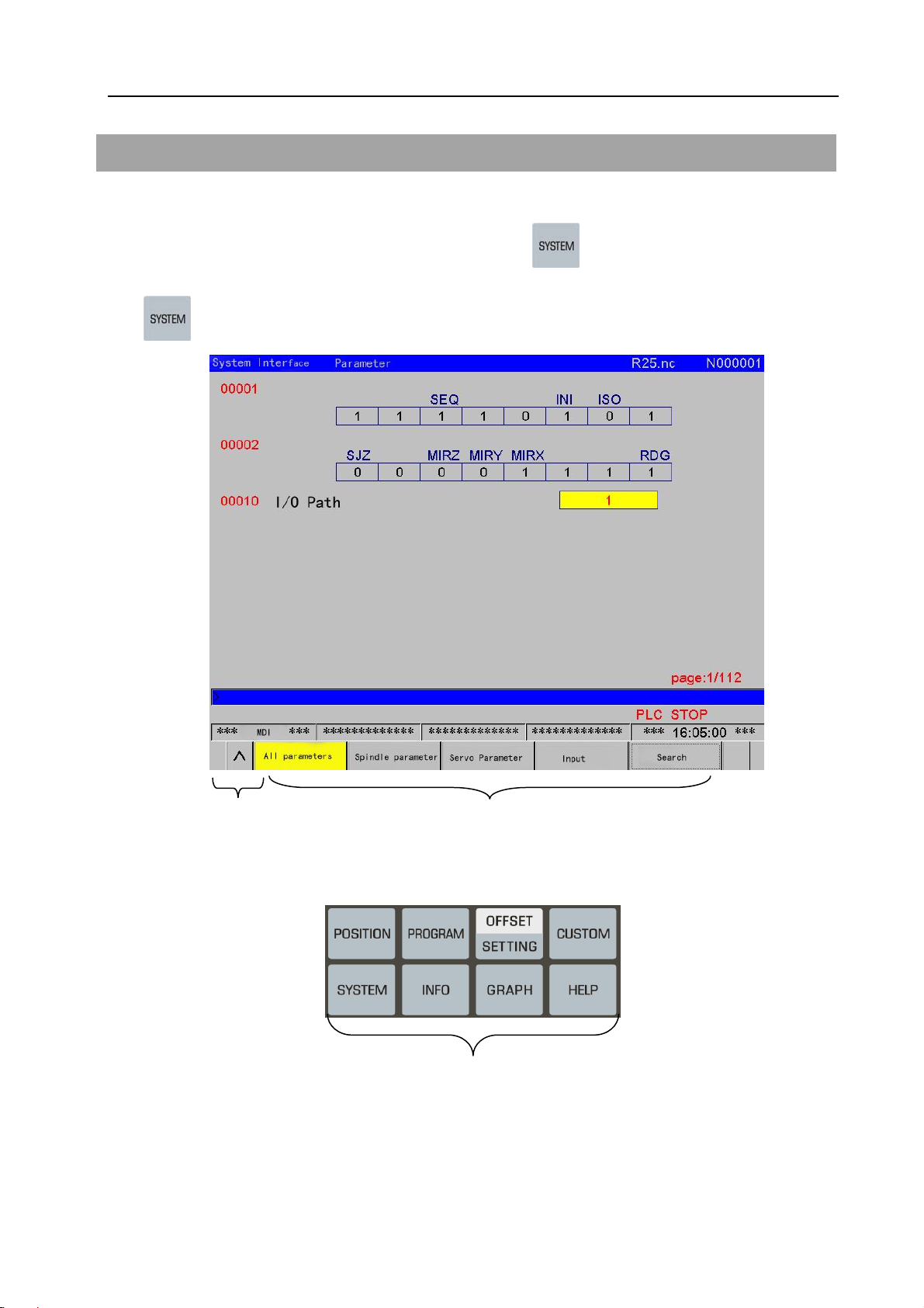
1 Parameter Display
The operations are shown below:
Volume Ⅲ Parameter
(1) Enter the parameter screen after the function key
times, or press the [Parameter] and [Operation] soft keys subsequently after pressing the function
key
once.
on MDI panel is controlled for many
(2) The parameter screen consists of multiple pages. Use two steps to display the page that
contains the parameter you want to display.
(a) The required relative parameters are selected using the soft key, and then the page to be
Return to the manual
Soft Keyboard
Fig.1-1
Fig.1-2 Function keys
1
Page 11
GSK25i Milling CNC System User Manual
found by the page keys or cursor move keys.
(b) The parameter numbers to be displayed are input from keyboard, and press the [search]
softkey to search, then the specified parameter page is displayed, and the cursor is positioned to the
specified parameter (the data part is turned into the selected color).
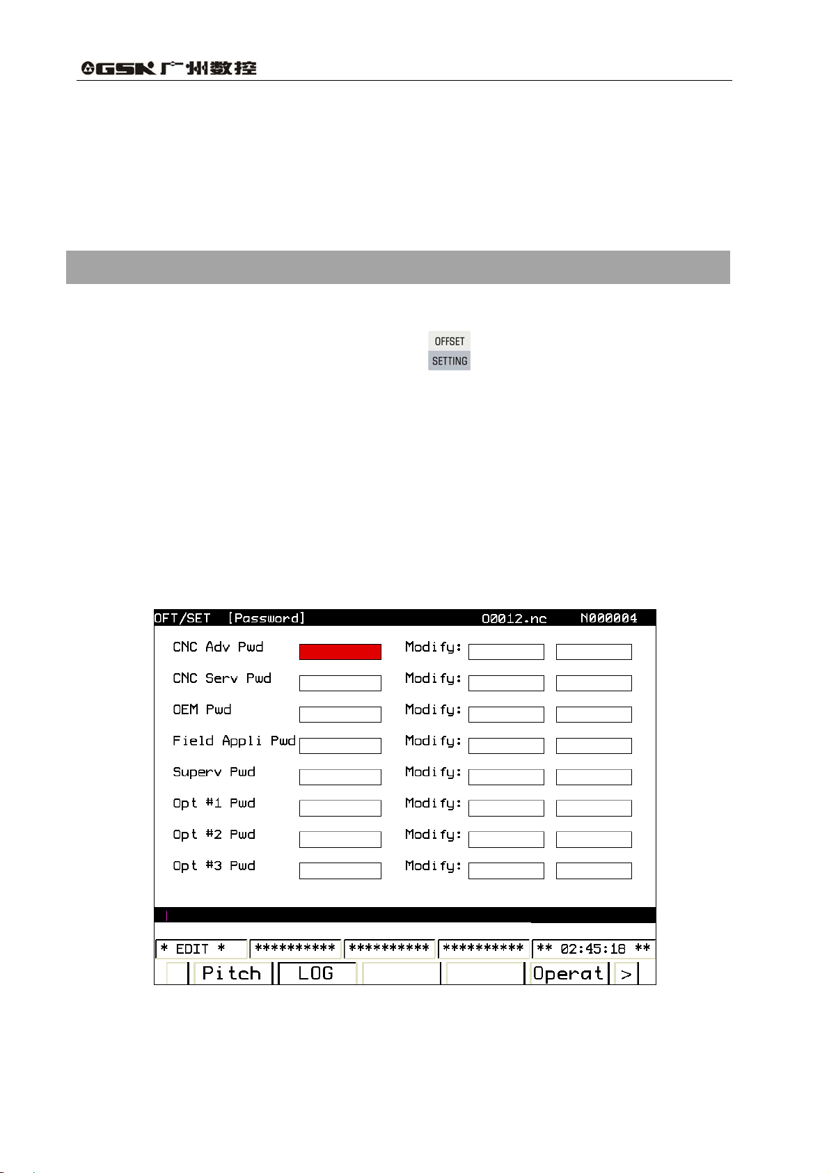
2 Parameter Setting in the Mode of MDI
The operation steps of parameters setting are shown below:
(1) Enter the offset setting page by pressing the
password.
To prevent the machining program and CNC parameters from being maliciously modified, the
GSK 25i offers an authority setting function and the password can be divided into 9 levels, from the
higher to the lower level, such as the 0 level (the system high level), the 1st level (the system service),
the 2nd level (the machine manufacturer), the 3rd level (the installation and debugging), the 4th level
(the terminal administration), as well as the 5th level (the operator 1 level), the 6th level (the operator
2 level), the 7th level (the operator 3 level) and the lowest default level (see the figure 2-1). The 0
level is enjoys the highest protection; contrarily, the lowest levels are from 5 to 7, and the highest level
can be administrated the lowest levels, which is the low authority function. The parameter password
level is 3 except for the special explaination.
, and firstly to input the correspondence
Fig. 2-1
2
Page 12
Volume Ⅲ Parameter
Level 0: the highest authority, reserved by the developer.
Level 1: It is used for the system manufacturer service, which can modified various data.
Level 2: The PLC program, PLC note and the pitch error compensation are modified. The PLC
and the pitch error compensation files are input or output. The user customized interface authority is
modified/ input or output.
Level 3: The parameter and PLC source data can be modified; the PLC operation is
started/stopped; the alarm/operation messages are eliminated; and the files are input or output, and
the system, interpolation and positional control maintenance softwares can be upgraded.
Level 4: The program, tool offset, setting, workpiece coordinate system offset and macro
program value are modified; these files are input or output and it also has the authority to modify the
passward.
th
The 5
, 6th and 7th levels: it is an operation authorized to corresponding person with
bit-parameter by the end user administrator.
The lowest level default by the system: it is an authority operation donated with bit-parameter by
end user administrator; no password inputs.
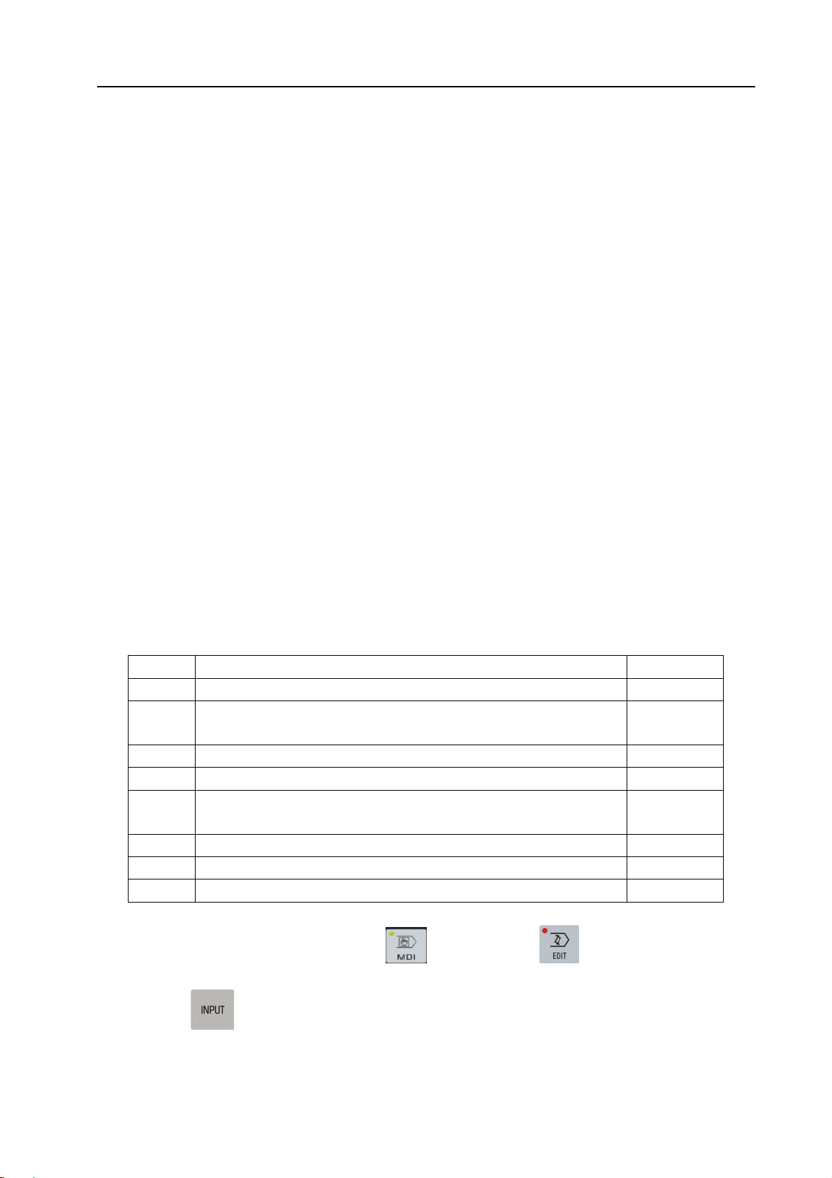
The bit-parameter definitions are authorized by the end user administrator, refer to the following table:
Bit Significance Note
0 Modify/input or output the authority of G code program. Authority
1 Modify the authority of geometrical tool offset/input or output tool
Authority
offset.
2 Modify the authority of wear tool offset/input or output tool offset. Authority
3 Modify the authority of setting Authority
4 Modify/input or output the authority of a workpiece coordinate
Authority
system offset.
5 Modify/input or output the authority of a macro program value Authority
6 Reserved
7 Reserved
(2) In the [MDI/Edit] mode, the MDI mode and Edit mode can be selected, and the
cursor can be moved based on the password authority to the required items.
(3) Press the
key, the corresponding level password can be input. If the password is correct,
a “correct password” may be displayed in the system; otherwise a “wrong password input” may occur.
(4) After the corresponding parameters are modified, the password is cancelled after logging out.
3
Page 13
GSK25i Milling CNC System User Manual
3 Setting or Maintaining the System Parameters by PC Instruction
Control Unit Software
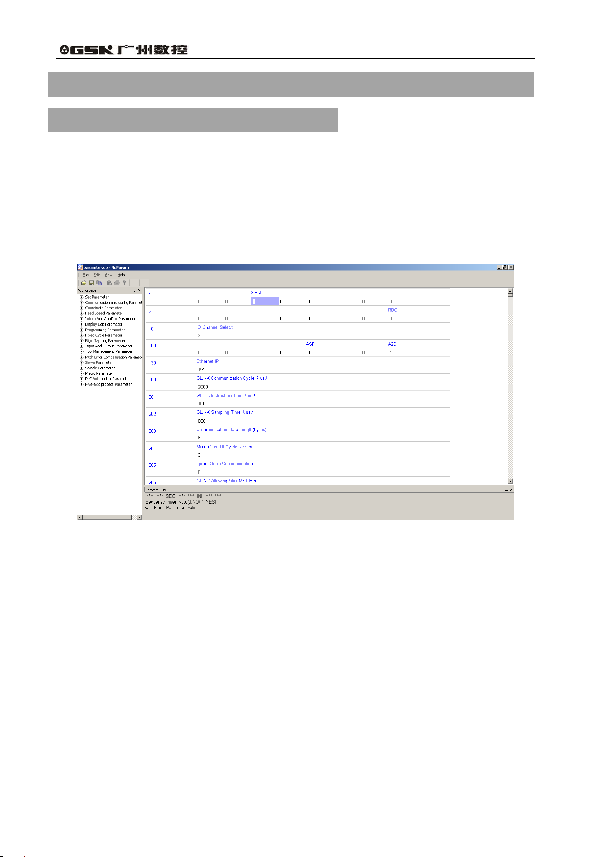
3.1 Editing of System Parameters
This software can be edited the system parameter on CNC in the program, and the
corresponding backup parameter files can be uploaded and downloaded through the internet. (Refer
to the Fig. 3-1, Fig. 3-2 and Fig. 3-3)
Fig.3-1 Editing the system parametersⅠ (Editing of the bit parameters)
4
Page 14
Volume Ⅲ Parameter
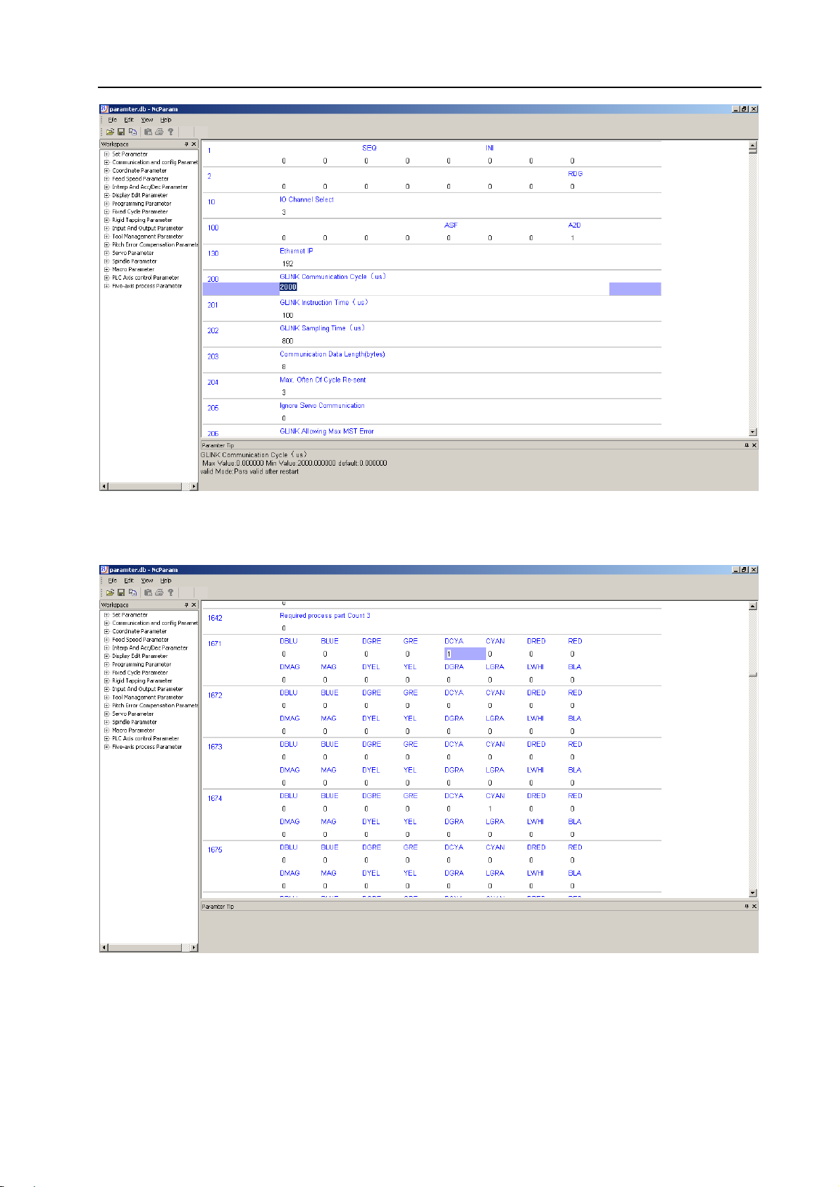
Fig.3-2 Editing the system parameters II (Editing of data parameters)
Fig.3-3 Editing the system parameters III (Editing of color parameters)
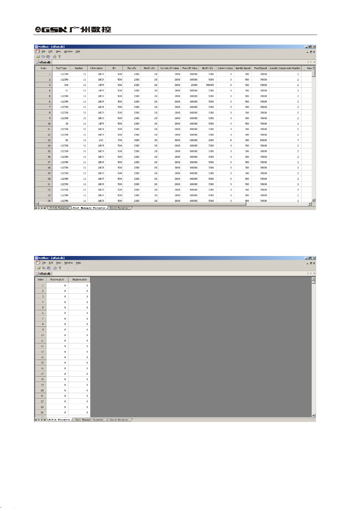
3.2 Editing of Tool and Offset Parameter
Editing of the tool and offset parameter is as the Fig. 3-4.
5
Page 15
GSK25i Milling CNC System User Manual
Fig. 3-4 Editing of tool and offset parameter
3.3 Editing of the Pitch Error Compensation Data
Editing the pitch error compensation data is as Fig. 3-5.
Fig. 3-5 Editing of the pitch error compensation data
6
Page 16
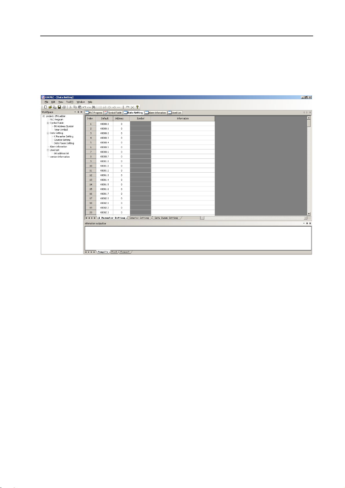
3.4 Editing of PLC Parameter
Editing the PLC parameter is as Fig. 3-6.
Volume Ⅲ Parameter
Fig. 3-6 Editing of PLC parameter
7
Page 17
GSK25i Milling CNC System User Manual
4 Parameter Explanation
[Parameter type]
The system parameters can be divided into several types based upon the following parameters
(refer to the fig. 4-1).
Table 4-1 data type and data effective range
Data type Effective data range
Bit
Bit axis
Integrated
Integral axis
Real number
Real number axis
The displayed number of axis type is determined on the total setting axis amount.
-99999999~99999999
-99999999~99999999
-99999999~99999999
-99999999~99999999
[Parameter explanation format]
The system parameter can be defined based on the following format.
Parameter number Parameter significance explanation
It is important to notice that the cautions may occur in the notice column to remind the user
Note
1. Notice 1
2. Notice 2
3. Notice 3
4,……
0 or 1
0 or 1
4.1 Parameter Setting (1~99)
7# 6# 5# 4# 3# 2# 1# 0#
0001
[Data type] Bit
[Data range] 0 or 1
INI: Unit of input
0:In mm
1:In inches
SEQ: Automatic insertion of sequence numbers
0:Not performed
1:Performed
8
SEQ INI
Page 18
Note:
The incremental of sequence number is set in parameter No.1621.
[Standard setting] 0 0 0 0 0 0 0 0
7# 6# 5# 4# 3# 2# 1# 0#
Volume Ⅲ Parameter
0002
RDG
[Data type] Bit
[Data range] 0 or 1
RDG: Remote diagnosis is
0:Not performed
1:Performed
Standard setting] 0 0 0 0 0 0 0 0
[
0010
I/O CHANNEL selection 3
[Data type] Integrated type
[Data range] 0-4
[
Standard setting]
Setting value Significance
0 RS232C serial port
1 Reserved
2 Reserved
3 USB interface
4 Ethernet interface
4.2 Communication Parameter (100~999)
7# 6# 5# 4# 3# 2# 1# 0#
0100
[Data type] Bit type
[Data range] 0 or 1
A2D: DSP loading method
0:DSP directly start mode
1:Loading DSP using cnc program
ASF:The current file of previous one is whether to save automatically while the file is loaded.
0:Yes
1:No
[
Standard set] 0 0 0 0 0 0 0 1
ASF A2D
9
Page 19
GSK25i Milling CNC System User Manual
0130
Ethernet IP address 192
[Data type] Integrated type
[Data range] 0-255
Note
For example: The value of IP:192.168.2.10 is 10 (192.168.2 is a fixed
value)
200
GSK-LINK communication period 200000
[Data type] Integrated type
[Data unit] 10ns
[Data range] 10000~1000000(100us-10ms)
201
GSK-LINK command time 10000
[Data type] Integrated type
[Data unit] 10ns
[Data range] 100~1000000
202
GSK-LINK sampling time 80000
[Data type] Integrated type
[Data unit] 10ns
[Data range] 100~1000000
203
The length of period communication data 8
[Data type] Integrated type
[Data unit] Byte
[Data range] 6~16(Required in multiples of 2)
204
The maximum period repeated times 3
[Data type] Integrated type
[Data unit]
[Data range] 0~16
205
Servo communication ignorance 0
[Data type] Integrated
[Dtat unit]
[Data range] 0~1
10
Page 20
Note:
The system may ignore the servo net communication when it is set to
1, which is mainly used for debugging; when this parameter is set, the
power must be turned off before operation is continued.
4.3 Coordinate Parameter (1000~1199)
7# 6# 5# 4# 3# 2# 1# 0#
Volume Ⅲ Parameter
1000
ISC INM
[Data type] Bit
[Data range] 0 or 1
INM: Least command increment on the linear axis
0:In mm (Metric system)
1:In inches (Inch system)
ISC:The least move unit
0:0.001mm, 0.001deg
1:0.0001mm, 0.0001deg
Note:
When this parameter is set, the power must be turned off before
operation is continued.
Standard setting] 0 0 0 0 0 0 1 0
[
7# 6# 5# 4# 3# 2# 1# 0#
1001
SFD DLZ
[Data type] Bit
[Data range] 0 or 1
DLZ: Function setting the reference position without dog
0:Disabled
1:Enabled
SFD: The function for shifting the reference position is
0:Not used
1:Used
[Standard setting] 0 0 0 0 0 0 0 0
11
Page 21
GSK25i Milling CNC System User Manual
7# 6# 5# 4# 3# 2# 1# 0#
1002
EDN EDP HJZ
[Data type] Bit
[Data range] 0 or 1
HJZ: When a reference position is already set:
0: Manual reference position return is performed with deceleration dogs.
1: Manual reference position return is performed using rapid traverse without
deceleration dogs.
EDP: External deceleration signal in the positive direction for each axis
0: Valid only for the rapid traverse
1: Valid for rapid traverse and cutting feed
EDN: External deceleration signal in the negative direction for each axis
0: Valid only for rapid traverse
1: Valid for rapid traverse and cutting feed
[
Standard setting] 0 0 0 0 1 0 0 0
7# 6# 5# 4# 3# 2# 1# 0#
1004
ZMI
[Data type] Bit axis
[Data range] 0 or 1
RRLn: Relative coordinates are
0: Not rounded by the amount of the shift per one rotation
1: Rounded by the amount of the shift per one rotation
ZMIx: Reference position return direction is set for each axis
0: In positive
1: In negative
Note:
When this parameter is set, the power must be turned off before
operation is continued.
Standard setting] 0 0 0 0 0 0 0 0
[
1020
Program axis name for each axis
[Data type] Integrated axis
[Data range] 0~127
X RRLn
12
Note
The display name is ASCII code, and the allowable input values are
X-88, Y-89, Z-90, A-65, B-66 and C-67.
Page 22
Volume Ⅲ Parameter
1021
The attribute of each axis in the basic
coordinate system
[Data type] Integrated
[Data range] 0~7
Setting value Significance
0 Neither the basic three axes nor a parallel axis
1 X axis of the basic three axes
2 Y axis of the basic three axes
3 Z axis of the basic three axes
4 Axis parallel to the X axis
5 Axis parallel to the Y axis
6 Axis parallel to the Z axis
1022
Servo logic address for each axis
[Data type] Integrated
[Data range] 0~25
Note
The setting of servo logic address is related to the connection of servo
network, the 1
is 0, according to this, servo logic address is its corresponding set
value; Usually, set a same value both the control axis number and the
controlled axis number.
1023
st
slave station connected from the system P1 terminal
7# 6# 5# 4# 3# 2# 1# 0#
[Data type] Bit axis
[Data range] 0 or 1
AXUn: Enabling for each axis is
0: Not used
1: Used
ISRn: It is either rotation axis or pallel axis for each axis
0: Pallel axis
1: Rotation axis
[Standard setting] 0 0 0 0 0 0 0 1
7# 6# 5# 4# 3# 2# 1# 0#
ISRn AXUn
1030
[Data type] Bit
[Data range] 0 or 1
RMOD: G code rotation command movement method
0: The approximate principle moves to the nearest position
ITI IDX ABS REL RMOD
13
Page 23
GSK25i Milling CNC System User Manual
1: Value magnitude moves
REL: Relative coordinate display of rotation axis
0: Out of the 360°
1: Within 360°
ABS: Absolute coordinate display of rotation axis
0: Out of the 360°
1: Within 360°
IDX: Index table indexing sequence.
0: Type A
1: Type B
ITI: The index function of the index table is:
0: Disabled
1: Enabled
[
Standard setting] 0 0 0 0 0 0 0 0
7# 6# 5# 4# 3# 2# 1# 0#
1031
[Data type] Bit
[Data range] 0 or 1
RLC: Local coordinate system is
0: Not cancelled by reset
1: Cancelled by reset
G52: In local coordinate system setting, a cutter compensation vector is
0: Not considered
1: Considered
[Standard setting] 0 0 0 0 1 0 0 0
1040
External workpiece origin offset value 0
[Data type] Real number axis
[Data unit] mm
[Data range] -9999.9999~9999.9999
1041
The origin offset amount of workpiece
coordinate system 1(G54)
G52 RLC
0
[Data type] Real number axis
[Data unit] mm
[Data range] -9999.9999~9999.9999
14
Page 24
Volume Ⅲ Parameter
1042
The origin offset amount of workpiece
[Data type] Real number axis
[Data unit] mm
[Data range] -9999.9999~9999.9999
1043
The origin offset amount of workpiece
[Data type] Real number axis
[Data unit] mm
[Data range] -9999.9999~9999.9999
1044
The origin offset amount of workpiece
[Data type] Real number axis
[Data unit] mm
[Data range] -9999.9999~9999.9999
1045
The origin offset amount of workpiece coordinate
0
coordinate system 2(G55)
0
coordinate system 3(G56)
0
coordinate system 4(G57)
0
system 5(G58)
[Data type] Real number axis
[Data unit] mm
[Data range] -9999.9999~9999.9999
1046
The origin offset amount of workpiece coordinate
[Data type] Real number axis
[Data unit] mm
[Data range] -9999.9999~9999.9999
1050
Coordinate value of the 1
each axis in the mechanical coordinate system
[Data type] Real number axis
[Data unit] mm
[Data range] -9999.9999~9999.9999
Note:
When this parameter is set, the power must be turned off before
operation is continued.
system 6(G59)
st
reference position on
0
0
15
Page 25

GSK25i Milling CNC System User Manual
1051
Coordinate value of the 2
each axis in the mechanical coordinate system
[Data type] Real number axis
[Data unit] mm
[Data range] -9999.9999~9999.9999
Note:
When this parameter is set, the power must be turned off before
operation is continued.
1052
Coordinate value of the 3rd reference position on
each axis in the mechanical coordinate system
[Data type] Real number axis
[Data unit] mm
[Data range] -9999.9999~9999.9999
nd
reference position on
0
0
Note
When this parameter is set, the power must be turned off before
operation is continued.
1053
Coordinate value of the 4th reference position
on each axis in the mechanical coordinate
[Data type] Real number axis
[Data unit] mm
[Data range] -9999.9999~9999.9999
Note
When this parameter has been set, the power must be turned off
before operation is continued.
1060
Amount of a shift per one rotationof a feed
0
system
0
axis
[Data type] Real number axis
[Data unit] mm or degree
[Data range] 0~999.9999
Note
When this parameter is set, the power must be turned off before
operation is continued.
16
Page 26

1068
Amount of rotation angle per one rotation
[Data type] Real number axis
[Data unit] Degree
[Data range] 0~9999.9999
Note
1. This parameter is used during cylinderical interpolation.
2. When this parameter is set, the power must be turned off before
operation is continued.
7# 6# 5# 4# 3# 2# 1# 0#
Volume Ⅲ Parameter
360
of a revolution axis
1070
LZR
[Data type] Bit
[Data range] 0 or 1
OUT: The area inside or outside of the stored stroke check 2 is set as an inhibition area.
0: Inside
1: Outside
OT2: Whether stored stroke check 2 is checked for each axis is set.
0: Stored stroke check 2 is not checked.
1: Stored stroke check 2 is checked.
OT3: Whether stored stroke check 3 is checked for each axis is set.
0: Stored stroke check 3 is not checked.
1: Stored stroke check 3 is checked.
XWG: Overtravel alarm switch
0: Alarm ON
1: Alarm OFF
LZR: Checking of stored stroke check 1 during the time from power-on to the manual
reference position return.
0: Not checked
1: Checked
[
Standard setting] 0 0 0 0 0 0 0 0
1080
Coordinate value of stored stroke check 1 in the
positive direction on each axis.
XWG
OT3 OT2
OUT
999999.9999
[Data type] Real number axis
[Data unit] mm
[Data range] 0~999999.9999
17
Page 27

GSK25i Milling CNC System User Manual
1081
Coordinate value of stroed stroke check 1 in the
negative direction on each axis.
[Data type] Real number axis
[Data unit] mm
[Data range] -999999.9999~0
1082
Coordinate value of stored stroke check 2 in the
positive direction on each axis.
[Data type] Real number axis
[Data unit] mm
[Data range] 0~999999.9999
1083
Coordinate value of stored stroke check 2 in the
negative direction on each axis.
-999999.9999
999999.9999
-999999.9999
[Data type] Real number axis
[Data unit] mm
[Data range] -999999.9999~0
1084
Coordinate value of stored stroke check 3 in the
positive direction on each axis.
[Data type] Real number axis
[Data unit] mm
[Data range] 0~999999.9999
1085
Coordinate value of stored stroke check 3 in the
negative direction on each axis.
[Data type] Real number axis
[Data unit] mm
[Data range] -999999.9999~0
1100 Machine struction type 12
999999.9999
-999999.9999
[Data type] Integrated
[Data range] 0~21
1101 Controlled axis number of the 1
[Data type] Integrated
[Data range] 0~5
18
st
rotation axis 4
Page 28

1102 The axis direction of the 1
[Data type] Integrated
[Data range] 0~5
1103 The rotation direction of the 1
[Data type] Integrated
[Data range] 0: negative/ 1: positive
st
1104 The 1
angular aixs
rotation axis is an inclination angle for
[Data type] Real number
[Data unit] deg
[Data range] -999999.9999 ~ 999999.9999
1105 The controlled axis number of the 2
axis
Volume Ⅲ Parameter
st
rotation axis 2
st
rotation axis 1
nd
rotation
0
5
[Data type] Integrated
[Data range] 0~5
1106 The axis diretion of the 2
[Data type] Integrated
[Data range] 0~5
1107 The rotation direction of the 2
[Data type] Integrated
[Data range] 0: negative/ 1: positive
nd
1108 The 2
the angular axis
rotation axis is an inclination angle of
[Data type] Real number
[Data unit] deg
[Data range] -999999.9999 ~ 999999.9999
1109 The axis direction of tool axis 3
nd
rotation axis 3
nd
rotation axis 1
0
[Data type] Integrated
[Data range] 0~3
19
Page 29

GSK25i Milling CNC System User Manual
1110
The position of index table 0
[Data type] Real number axis
[Data unit] mm
[Data range] -9999.9999~9999.9999
Note
Coordinate parameters of three axes X, Y and Z are included
1111
Offset vector between the 1st and 2nd working
table rotation axes
[Data type] Real number axis
[Data unit] mm
[Data range] -9999.9999~9999.9999
Note
Coordinate parameters of three axes X, Y and Z are included
1112
Offset vector between the tool axis and tool
rotation axis
0
0
[Data type] Real number axis
[Data unit] mm
[Data range] -9999.9999~9999.9999
Note
Coordinate parameters of three axes X, Y and Z are included
1113
Offset vector between the 2nd and 1st tool rotation
axes
[Data type] Real number axis
[Data unit] mm
[Data range] -9999.9999~9999.9999
Note
Coordinate parameters of three axes X, Y and Z are included
1114
Tool post offset 0
[Data type] Real number axis
[Data unit] mm
[Data range] -9999.9999~9999.9999
0
20
Page 30

4.4 Feedrate Parameter (1200~1399)
7# 6# 5# 4# 3# 2# 1# 0#
Volume Ⅲ Parameter
1200
[Data type] Bit
[Data range] 0 or 1
RPD: Manual rapid traverse during the period from the power-on time to the completion of the
reference position return.
0: Disabled
1: Enabled
RF0: When the rapid feedrate override is F0,
0: The machine tool does not stop moving.
1: The machine tool stops moving.
RDR: When the rapid traverse is performed,
0: Dry run is disabled.
1: Dry run is enabled.
[
Standard setting] 0 0 0 0 0 0 0 0
1210
Dry run speed (common to all axes) 10000
[Data type] Real number
[Data unit] mm/min
[Data range] 0~1000000
RDR RF0 RPD
Note
The dry run speed is set when the manual feedrate is set to 100%.
1211
[Data type] Real number
[Data unit] mm/min
[Data range] 0~1000000
Note
The feedrate is set when the automatic feedrate is set to 100%.
1224
[Data type] Real number
[Data unit] mm/min
[Data range] 0~1000000
The cutting feedrate occurs by default in the
automatic mode
The maximum cutting composite feedrate
(common to all axes)
1000
4000
21
Page 31

GSK25i Milling CNC System User Manual
1225
Maximum cutting feedrate for each axis in the
automation mode
[Data type] Real number axis
[Data unit] mm/min or degree/min
[Data range] 0~1000000
1226
Rapid traverse rate for each axis in the
automation mode
[Data type] Real number axis
[Data unit] mm/min or degree/min
[Data range] 0~1000000
Note
1. The rapid traverse rate is set when the rapid traverse rate is set to
100%.
1227
The top allowable speed of move axis is shown
when it is started or stopped suddenly during
the linkage.
4000
10000
1000
[Data type] Real number axis
[Data unit] mm/min or degree/min
[Data range] 0~1000000
1228
The top allowable speed of move axis is shown
when it is performed in negative suddenly
during the linkage.
[Data type] Real number axis
[Data unit] mm/min or degree/min
[Data range] 0~1000000
1229
The top allowable acceleration speed
of move axis is shown when it is
performed in negative suddenly during
the linkage.
[Data type] Real number axis
[Data unit] m/s
2
[Data range] 0~90000000
1000
0.3
[The rotation
axis is 75]
22
Page 32

1231
F0 speed of rapid traverse feedrate override
(common to all axes)
[Data type] Real number
[Data unit] mm/min or degree/min
[Data range] 0~100000
1232
Feedrate in manual continuous feed (JOG feed)
for each axis
[Data type] Real number axis
[Data unit] mm/min or degree/min
[Data range] 0~100000
Note
JOG feedrate is set when manual feedrate is 100%.
1233
Manual rapid traverse rate for each axis
[Data type] Real number axis
[Data unit] mm/min or degree/min
[Data range] 0~100000
Volume Ⅲ Parameter
100
1000
3000
Note
1. Rapid traverse rate is set when the rapid traverse rate is 100%,
and the value set by No.1226 [the top speed at rapid traverse rate]
is employed when this parameter is set to 0.
1234
FL rate of the reference position return for each
axis
[Data type] Real number axis
[Data unit] mm/min or degree/min
[Data range] 0~15000
1235
Reference position return speed for each axis
[Data type] Real number axis
[Data unit] mm/min or degree/min
[Data range] 0~100000
300
4000 [the rotation
axis is 2000]
23
Page 33

GSK25i Milling CNC System User Manual
1236
The 2
return for each axis
nd
FL speed of reference position
[Data type] Real number axis
[Data unit] mm/min or degree/min
[Data range] 0~100000
1239
[Data type] Real number
[Data unit] mm/min or degree/min
[Data range] 0~100000
1240
The maximum operation speed of single-step
[Data type] Real number
[Data unit] mm/min or degree/min
[Data range] 0~100000
1241
[Data type] Real number
[Data unit] mm/min or degree/min
[Data range] 0~100000
The top speed of manual feed
The maximum feed speed of MPG
7 [The rotation
axis is 2]
5000
10000
15000
4.5 Interpolation and Acceleration/Deceleration Control Parameter
(1400~1599)
7# 6# 5# 4# 3# 2# 1# 0#
1400
[Data type] Bit
[Data range] 0 or 1
PPCK: In-position check
0: Not performed
1: Performed
P ACD: The acceleration/deceleration mode before the interpolation
0: Linear type
1: Type S
[
Standard setting] 0 0 0 0 0 0 0 0
PACD PPCK
24
Page 34

Volume Ⅲ Parameter
7# 6# 5# 4# 3# 2# 1# 0#
1401
ALS WFM DEF EFL
[Data type] Bit
[Data range] 0 or 1
EFL: The flag of the transition of small line segment fold
0: No employed
1: Employed
DEF: The speed is whether to control the speed variable when the controlled axis is stopped
suddenly
0: Not considered
1: Considered
WFM: MPG interpolation mode
0: It is treated by the impounding reservoir mode
1: It is treated by the real-time mode
ALS: Automatic corner feed function
0: Invalid
1: Valid
[
Standard setting] 0 0 0 0 0 0 0 0
7# 6# 5# 4# 3# 2# 1# 0#
1403
RCOK RBK HXS
[Data type] Bit
[Data range] 0 or 1
HXS: The rotation diretion between MPG and each axis
0: Different
1: Same
RBK: The backlash compensation is performed between the cutting and rapid traverse.
0: Not separately
1: Separately
RCOK: Backlash compensation
0: Not performed
1: Performed
[
Standard setting] 0 0 0 0 0 0 1 0
1404
Curve frequency of Nurbs interpolation
[Data type] Integrated
[Data unit] times
[Data range] 1~4
3
25
Page 35

1405
[Data type] Integrated
[Data unit] Point/mm
[Data range] 5~1000
1406
[Data type] Integrated
[Data unit] Section
[Data range] 0~2000
1407
[Data type] Integrated
[Data unit] Section
[Data range] 10~500
1409
[Data type] Integrated
[Data unit] Section
[Data range] 0~2000
GSK25i Milling CNC System User Manual
Standard indensity setting of Nurbs curve
interpolation
Pre-read sections in its look-ahead treatment
The maximum program sections of Nurbs curve
interpolation
Prospective treatment program section amount
10
1000
200
10
Note
The prospective program section amount is set when adopting the
prospect, and the 0 does not indicate prospect.
100
1410
Acceleration/deceleration type S and time
constant T1 are specified before the rapid
traverse feed is performed
[Data type] Integrated axis
[Data unit] ms
[Data range] 1~4000
The parameter value of its corresponding number is indicated by the P+ parameter number , such
as, P A1233 means the No. 1233 pa rameter. The acceleration/deceleration calculation mode of type S
is shown below, where, the t
acceleration time, and A
indicates an uniform acceleration time, t2 means a jerk and decelerating
1
is the maximum acceleration.
m
26
Page 36

Volume Ⅲ Parameter
t
a
V
2
t
1
=0.
Q
V
3
2A
R
2/2t
A)*tt(t
V
++
2
m
+
V
m
t
2
m
A
m
=
=
m211
)t(2t
21
A
m
O
As the above figure mentioned, the ladder area is:
The maximum acceleration calculation is concluded:
And, the calculation of jerk time is:
The linear acceleration/deceleration can be regarded as a special example when the type S
acceleration/deceleration is on the state of t
Before the Goo rapid traverse, the maximum acceleration calculation format of
acceleration/deceleration type S is:
P2
×
A
m00
=
1226
+×
14111410
P
V
1
2/2t
J =
m
2
, And the maximum acceleration calculation format of jerk type
)PP(2
S before the Goo rapid traverse is
Note
1. When the acceleration or jerk calculation is used this format during
the actual application; it is very necessary to note that the unit
conversion must be performed in terms of the unit of parameters.
1411
[Data type] Integral axis
[Data unit] ms
[Data range] 0~4000
S-type acceleration/deceleration time constant
T
at the rapid traverse feed
2
Note
1. When the acceleration or jerk calculation is used this format during
the actual application; it is very necessary to note that the unit
conversion must be performed in terms of the unit of parameters.
J =
m00
2A
P
m00
1411
.
100
27
Page 37

GSK25i Milling CNC System User Manual
1440
[Data type] Real number axis
[Data unit] m/ s
related to the parallel axis.
[Data range] 0~25000
2
, the rotation axis is: degree/s2, a general rotation axis value is up to 250 folds
Note
It is only valid to the linear acceleration/deceleration control.
1442
[Data type] Real number
[Data unit] m/ s
[Data range] 0~25000
[Data type] Real number axis
[Data unit] m/s
to the parallel axis.
[Data range] 0~25000
2
1444
Mechanical zero return acceleration speed by
default
2
, the rotation axis is: degree/s2, a general rotation axis value is up to 250 folds related
1445
[Data type] Real number
[Data unit] m/ s
[Data range] 0~25000
2
1446
[Data type] Real number
[Data unit] m/s
[Data range] 0~25000
[Data type] Real number
[Data unit] m/s
[Data range] 0~25000
2
2
1447
The maximum acceleration speed
0.4 [The
rotation axis is
100]
The maximum acceleration speed of the circular
arc interpolation feed
0.139[The
rotation axis
is 80]
The acceleration speed is performed during
deceleration when dwelling or RESETTING in
the process of operation
MPG acceleration speed
Manual acceleration speed
0.5
0.5
0.5
0.5
28
Page 38

Volume Ⅲ Parameter
1471
[Data type] Real number
[Data unit] mm
[Data range] 0~1
1472
[Data type] Real number
[Data unit] mm
[Data range] 0~1
1473
[Data type] Real number
[Data unit] mm
[Data range] 0~1
1480
[Data type] Integral axis
[Data unit] ms
[Data range] 0~4000
The maximum acceleration calculation format of acceleration/deceleration type S before the Goo
rapid traverse is:
The acceleration/deceleration S-type time
constant T1 before cutting feed
Cutting feed in-position accuracy
Circular arc interpolation control accuracy
The maximum contour error of the system
0.001
0.001
0.001
16
2
P
×
A
acceleration/deceleration type S before the Goo rapid traverse is
=
01
m
Note
1. When the acceleration or jerk calculation is used this format during the
actual application; it is very necessary to note that the unit conversion
must be performed in terms of the unit of parameters.
1481
[Data type] Integral axis
[Data unit] ms
[Data range] 0~4000
1225
, and the maximum jerk calculation format of
)2(
PP
+×
14811480
Accleration/deceleration S type time constant
T2 before cutting feed
J =
01
m
2
16
P
A
1481
m
01
.
29
Page 39

Note
1. When the acceleration or jerk calculation is used this format during the
actual application; it is very necessary to note that the unit conversion
must be performed in terms of the unit of parameters.
1493
[Data type] Real number
[Data unit] mm
[Data rang] 0~50.0000mm
1494
[Datat type] Real number
[Data unit] deg
[Data range] 0~30
1495
[Datat type] Real number
[Data unit] deg
[Data range] 120~180
The least conversion corner of fold line transition
1500
[Datat type] Real number
[Data unit] deg
[Data range] 0~60
1501
[Datat type] Real number
[Data unit] mm/min
[Data range] 60~1000
The lowest federate of automatic corner deceleration
1502
[Datat type] Real number
[Data unit] %
[Data range] 0.00~100.00
GSK25i Milling CNC System User Manual
Judging the least distance of Nurbs interpolation
deceleration point
Judge the least corner of Nurbs interpolation
deceleration point
Two blocks’ boundary corner of the automatic
corner deceleration
The least circular arc cutting feed deceleration
rate inside the automatic corner override
1.000
10
150
0
120
50
30
Page 40

1503
[Datat type] Real number
The start distance of the internal corner override
[Data unit] 0.1mm
[Data range] 0~4000
1504
[Datat type] Real number
The end distance of the internal corner override
[Data unit] 0.1mm
[Data range] 0~3999
1505
[Datat type] Real number
[Data unit
[Data range] 0~9999.9999
] mm/min
The lowest speed of circular interpolation
Volume Ⅲ Parameter
1
1
200
4. 6 Editing Parameter Display (1600~1799)
7# 6# 5# 4# 3# 2# 1# 0#
1601
[Data type] Bit
[Data range] 0 or 1
ENG, CHI: Language selection
Standard setting] 0 0 0 1 0 0 0 0
[
1603
[Data type] Bit
[Data range] 0 or 1
DRL: The relative position display is whether to consider the tool length compensation
0: Considered
1: Not considered
DRC: The relative position display is whether to consider the tool radius compensation
0: Considered
1: Not considered
ENG CHI
ENG CHI Language display
0 * Simplified Chinese
1 0 English
7# 6# 5# 4# 3# 2# 1# 0#
DAC DAL DRC DRL
31
Page 41

GSK25i Milling CNC System User Manual
DAL: The absolute position display is whether to consider the tool length compensation
0: Considered
1: Not considered
DAC: The absolute position display is whether to consider the tool radius compensation
0: Considered
1: Not considered
[
Standard setting] 0 0 0 0 0 0 0 0
7# 6# 5# 4# 3# 2# 1# 0#
1605
NPA PLCD
[Data type] Bit
[Data range] 0 or 1
PLCD: PLC ladder diagram display
0: Not displayed
1: Displayed
NPA: Whether to shift to an alarm screen when the alarm occurs.
0: No
1: Yes
[
Standard setting] 0 0 0 0 0 0 0 1
7# 6# 5# 4# 3# 2# 1# 0#
1610
NE9 NE8
[Data type] Bit
[Data range] 0 or 1
NE8: Whether to forbid the subprogram edit of the program numbers from 8000 to 8999
0: Not forbidden
1: Forbidden
NE9: Whether to forbid the subprogram edit of the program numbers from 9000 to 9999
0: Not forbidden
1: Forbidden
[Standard setting] 0 0 0 1 0 0 0 1
1621
Automatically insert the incremental value in
10
sequence number
[Data type] Integrated
[Data range] 0~9999
1640
[Data type] Integrated
[Data range] 0~99999999
32
The required machining parts are added 1
0
Page 42

1641
[Data type] Integrated
[Data range] 0~99999999
1642
[Data type] Integrated
[Data range] 0~99999999
1671
[Data type] Bit
1672
[Data type] Bit
1673
[Data type] Bit
1674
[Data type] Bit
1675
[Data type] Bit
1676
[Data type] Bit
1677
[Data type] Bit
1678
[Data type] Bit
Volume Ⅲ Parameter
The required machining parts are added 2
The required machining parts are added 3
Main surface ground colour
Fixed output color
Dynamic output color
Selected basis color
Selected font color
The ground color of controllable parts
The selected color of controllable parts
The ground color of input column
0
0
33
Page 43

[Data type] Bit
[Data type] Bit
[Data type] Bit
[Data type] Bit
[Data type] Bit
[Data type] Bit
[Data type] Bit
[Data type] Bit
1679
1680
1681
1682
1683
1684
1685
1686
GSK25i Milling CNC System User Manual
The font color of input column
The ground color of title column
The font color of title column
The ground color of state column
The font color of state column
Alarm color
Setting-out color
Shared color
7# 6# 5# 4# 3# 2# 1# 0#
1687
[Data type] Bit
[Data range] 0 or 1
Note
DEF1-DEF3, the default color configuration program, the above-mentioned
configuration color can be regarded as valid as long as all default bits are
set to 0.
34
DEF3 DEF2 DEF1
Page 44

4. 7 Programming Parameter (1800~1999)
7# 6# 5# 4# 3# 2# 1# 0#
Volume Ⅲ Parameter
1800
DPI
[Data type] Bit
[Data range] 0 or 1
DPI: The decimal point is ignored when programming
0: It is treated as the least set unit
1: It is regarded as mm, sec
Starndard setting] 0 0 0 0 0 0 0 1
[
7# 6# 5# 4# 3# 2# 1# 0#
1801
G23 CLR G91 G19 G18 G01
[Data type] Bit
[Data range] 0 or 1
G01: The modul issues when the power is turned on or off
0: G00 mode
1:G01 mode
G18, G19: When the power is turned on or off, the panel selection is:
G19 G18 Panel selection
0 0 G17
0 1 G18
1 0 G19
G91: When the power is turned on or off, its set is:
0: G90 mode
1: G91 mode
CLR: When the reset is performed
0: The system is reset
1: The system is eliminated
G23: When the power is turned on
0: G22 mode
1: G23 mode
[
Standard setting] 1 0 0 0 0 0 0 0
7# 6# 5# 4# 3# 2# 1# 0#
1802
AD2
[Data type] Bit
[Data range] 0 or 1
AD2: More than two same addresses are specified in a same command.
0: Command is valid
1: System alarm
Standard set] 0 0 0 0 0 0 0 0
[
35
Page 45

GSK25i Milling CNC System User Manual
7# 6# 5# 4# 3# 2# 1# 0#
1803
M3B POL
[Data type] Bit
[Data range] 0 or 1
POL: Decimal point command address program
0: Used
1: Not used
M3B: M code number can be specified in program
0: One
1: Up to 3
[Standard setting] 0 1 0 0 0 0 0 0
1810
Allowable error of circular arc radius
[Data type] Real number
[Data unit] mm
[Data range] 0~9999.9999
Note
The circular arc radius error is not to be checked when the
set value is 0.
7# 6# 5# 4# 3# 2# 1# 0#
0.01
1850
SCR XSC SCL RIN
[Data type] Bit
[Data range] 0 or 1
RIN: The rotation angle of its coordinate rotation
0: Absolute coordinate command
1: G90/G9 command
SCL: Scaling for each axis
0: Disabled
1:Enabled
XSC: Scaling override for each axis
0: Disabled
1:Enabled
SCR: The scaling override unit
0: 0.001 times
1: 0.0001 times
[
Standard setting] 0 0 0 0 0 0 0 0
36
Page 46

1860
The rotation angle is used when the angle in
coordinate rotation does not occur.
[Data type] Real number
[Data unit] deg
[Data range] -360.000~ 360.000
1861
The scaling override is used when the scaling
command override does not occur.
[Data type] Real number
[Data range] 0~ 99.999
1862
[Data type] Real number axis
[Data range] 0~ 99.999
7# 6# 5# 4# 3# 2# 1# 0#
Scaling for each axis
Volume Ⅲ Parameter
0
1
1
1870
PDI MDL
[Data type] Bit
[Data range] 0 or 1
MDL: Single direction positioning G code (G60)
0: The modul code does not set
1: Modul code
PDI: Single direction positioning in-position check
0: Not performed
1: Performed
[Standard set] 0 0 0 0 0 0 0 0
1880
The direction and overtravel amount of single
direction positioning for each axis
[Data type] Real number axis
[Data unit] mm
[Data range] -999.9999~ 999.9999
1931
The least angle of index table
[Data type] Real number
[Data unit] deg
[Data range] 0~360.000
0
0
37
Page 47

GSK25i Milling CNC System User Manual
7# 6# 5# 4# 3# 2# 1# 0#
1940
SKF
[Data type] Bit
[Data range] 0 or 1
SKF: Whether the G31 skip command is valid to the dry run, override and authomatic
acceleration/deceleration:
0: Valid
1: Invalid
Standard set] 0 0 0 0 0 0 0 0
[
7# 6# 5# 4# 3# 2# 1# 0#
1950
MOU
[Data type] Bit
[Data range] 0 or 1
MOU: Whether to input the M, S, T and B codes when the program is restarted:
0: Not output
1: Output
Standard set] 0 0 0 0 0 0 0 0
[
1960
The move sequence for each axis moves to the
program restart position
[Data type] Integral axis
[Data range] 0~ Controllable axis number
7# 6# 5# 4# 3# 2# 1# 0#
1971
ESC ESR
[Data type] Bit
[Data range] 0 or 1
ESR: External program number index
0: Ineffective
1: Effective
ESC: The reset is input from ESTB input to index.
0: Index performed
1: Not performed
[Standard set] 0 0 0 0 0 0 0 0
38
Page 48

4.8 Fixed Cycle Parameter (2000~2099)
7# 6# 5# 4# 3# 2# 1# 0#
Volume Ⅲ Parameter
2000
M5B RD2 RD1 FXY
[Data type] Bit
[Data range] 0 or 1
FXY: The drilling axis in the drilling canned cycle is:
0: Always the Z-axis
1: The axis selected by the program
RD2, RD1 Set the retraction axis direction of G76 or G87
RD2 RD1 G17 G18 G19
0 0 +X +Z +Y
0 1 -X -Z -Y
1 0 +Y +X +Z
1 1 -Y -X -Z
M5B: G76 G87 spindle orientation
0: Outputs M05 before an orientated spindle stops
1: Not ouput M05 before an oriented spindle stops
[
Standard setting] 0 0 0 0 0 0 0 0
2010
Return d of high speed peck drilling G73 0.5
[Data type] Real number
[Data unit] mm
[Data range] 0~99.9999
2011
Clearance d of canned cycle G83 0.5
[Data type] Real number
[Data unit] mm
[Data range] 0~99.9999
2034
Clearance of small diameter peck drilling cycle 0.5
[Data type] Real number
[Data unit] mm
[Data range] 0~99.9999
39
Page 49

GSK25i Milling CNC System User Manual
4.9 Rigid Tapping Parameter (2100~2299)
2112
[Data type] Real number
[Data unit] mm
[Data range] 0~99.9999
2140
[Data type] Integrated
[Data unit] r/min
[Data range] 0~9999
2141
[Data type] Integrated
[Data unit] r/min
[Data range] 0~9999
2142
[Data type] Integrated
[Data unit] r/min
[Data range] 0~9999
2170
[Data type] Integrated
[Data unit] 0.01/s
[Data range] 0~9999
Return or clearance in peck tapping cycle 0.5
The maximum speed of spindle (the 1
gear) in rigid tapping
The maximum speed of spindle (the 2
gear) in rigid tapping
The maximum speed of spindle (the 3
gear) in rigid tapping
The position control circuit gain is performed
(the 1st step gear) between spindle and tapping
axis when the rigid tapping is performed.
st
step
nd
step
rd
step
1000
1000
1000
1000
Note
When this parameter is set, the power must be turned off before
operation is continued.
2171
[Data type] Integrated
[Data unit] 0.01/s
40
The position control circuit gain is performed
nd
(the 2
step gear) between spindle and tapping
axis when the rigid tapping is performed.
1000
Page 50

[Data range] 0~9999
Note
When this parameter is set, the power must be turned off
before operation is continued.
2172
[Data type] Integrated
[Data unit] 0.01/s
[Data range] 0~9999
Note
When this parameter is set, the power must be turned off before
operation is continued.
2180
[Data type] Integrated
[Data range] 0~32767
2181
[Data type] Integrated
[Data range] 0~32767
2182
[Data type] Integrated
[Data range] 0~32767
2210
[Data type] Integrated
[Data unit] Check unit
[Data range] 1~127
2211
[Data type] Integrated
Volume Ⅲ Parameter
The position control circuit gain is performed
(the 3rd step gear) between spindle and tapping
axis when the rigid tapping is performed.
Spindle circuit gain coefficient in rigid tapping
Spindle circuit gain coefficient in rigid tapping
Spindle circuit gain coefficient in rigid tapping
Spindle backlash compensating value of rigid
tapping (the 1
Spindle backlash compensating value of rigid
tapping (the 2nd step gear)
st
(the 1
(the 2nd step gear)
(the 3rd step gear)
step gear)
st
step gear)
1000
1000
1000
1000
10
10
41
Page 51

GSK25i Milling CNC System User Manual
[Data unit] Check unit
[Data range] 1~127
2212
Spindle backlash compensating value of rigid
[Data type] Integrated
[Data unit] Check unit
[Data range] 1~127
2221
[Data type] Real number
[Data unit] mm
[Data range] 0~9999.9999
10
tapping (the 3rd step gear)
Return value of rigid tapping 0.5
4.10 Parameter of Manual, Auto and MPG Operation (2300~2499)
7# 6# 5# 4# 3# 2# 1# 0#
2300
[Data type] Bit
[Data range] 0 or 1
JHD: MPG feed in JOG mode or incremental feed in MPG feed mode
0: Invalid
1: Valid
IHD: The travel increment of MPG is:
0: Output unit
1: Input unit
HCL: Whether the softkey is cleared the display of MPG interruption
0: Disabled
1: Enabled
HPF: When a MPG feedrate exceeding the rapit traverse rate is issued, the rate is clamped at
the rapid traverse rate and exceeded part of pulse
0: Ignored
HNGD JAG HPF HCL IHD JHD
1: Not ignored, but stored in the CNC
JAG: Manual absolute switch of system
0: OFF
1: ON
HNGD: Axis movement direction for rotation direction of MPG
0: Same in direction
1: Reverse in direction
[
Standard setting] 0 0 0 0 0 0 0 0
42
Page 52

2310
[Data type] 2-word
[Data unit] mm
[Data range] 0~10.000
2320
[Data type] Byte
[Data range] 1~3
2321
[Data type] Byte
[Data range] 1~127
2322
[Data type] Word
[Data range] 1~999
MP2(G19#5) MP1(G19#4) MPG movement
Volume Ⅲ Parameter
Least command increment setting for JOG feed
Number of MPG
MPG feedrate override m
MPG feedrate override n
0 0
0 1
1 0
1 1 Least input increment ×n
Least input increment ×1
Least input increment ×10
Least input increment ×m
0.001
2323
Allowable number of pulses that can be
accumulated during MPG feed
[Data type] 2-Word
[Data range] 0~99999999
4.11 Parameter (2500~2599) Input/Output
7# 6# 5# 4# 3# 2# 1# 0#
2501
[Data type] Bit
[Data range] 0 or 1
SWI: Position switch symbol
0: Invalid
1: Valid
DEC: Deceleration signal for reference position return
LTM DEC SWI
43
Page 53

GSK25i Milling CNC System User Manual
0: Deceleration is applied when the signal is 0.
1: Deceleration is applied when the signal is 1.
LTM: Hard limit treatment method
0: Hard limit deceleration treatment
1: Stops immediately
[
Standard setting] 0 0 0 0 0 0 0 0
2510
The delay time of strobe signal MF, SF, TF and
BF
[Data type] Integrated
[Data unit] ms
[Data range] 16~32767
2511
The acceptable width of the M, S, T and B
[Data type] Integrated
[Data unit] ms
[Data range] 16~32767
2512
Distributed address to the skip signal 0
[Data type] Integrated
[Data range] 0~127
64
64
completion signal
Note
1. It is invalid when the parameter is less than 10.
2513
[Data type] Integrated
[Data range] 0~127
Note
1. It is invalid when the parameter is less than 10.
2518
[Data type] Integrated
[Data unit] ms
[Data range] 0~1000
Distributed address to the measure arrival
signal
Output time of reset signal 100
0
44
Page 54

Volume Ⅲ Parameter
2540-2555
[Data type] Integrated
[Data range] 0~6
Note
1. Position switch function is valid when the bit SWI is set to 1.
2. Position switch function is invalid when the bit SWI is set to 0.
2556-2571
The maximum range of position switch positive 0
[Data type] Integrated
[Data range] 0~99999999
2572-2587
The maximum range of position switch negative 0
[Data type] Integrated
[Data range] -99999999~ 0
Position switch corresponds servo axis 0
4.12 Tool Administration Parameter (2600~2799)
7# 6# 5# 4# 3# 2# 1# 0#
2600
[Data type] Bit
[Data range] 0 or 1
TLB: Tool length compensation selection
0: Tool compensation A (Always Z axis irrespective of plane specification)
1: Tool compensation B (Axis perpendicular to plane specification)
Standard setting] 0 0 0 0 0 0 1 0
[
2601
[Data type] Bit
[Data range] 0 or 1
CCN: G28 command moves to the intermediate point in radius compensation
0: The radius compensation is cancelled in movement to an intermediated position
1: The radius compensation is not cancelled in movement to an intermediate position,
but is cancelled in movement to the reference position.
LVK: Tool length offset value
0: Not cleared, but held by reset
1: Cleared by reset
ODI: A cutter compensation amount is set using:
0: A diameter
TLB
7# 6# 5# 4# 3# 2# 1# 0#
ODI LVK CCN
45
Page 55

GSK25i Milling CNC System User Manual
1: A radius
Standard setting] 0 0 0 0 0 1 0 0
[
7# 6# 5# 4# 3# 2# 1# 0#
2602
G39 TPH CNI OIM
[Data type] Bit
[Data range] 0 or 1
OIM: When the unit is switched between the inch and metric systems, automatic tool offset
value conversion is:
0: Not performed
1: Performed
CNI: Interference check for radius compensation is:
0: Performed
1: Not performed
TPH: Tool format of cutter compensation
0: Type A
1: Type B
G39: The corner rounding function in radius compensation mode is:
0: Disabled
1: Enabled
[
Standard setting] 0 0 0 0 0 0 0 0
2610
The vector limit value is ignored when cutter
compensation moves along with the corner
external.
[Data type] Real number
[Data unit] mm
[Data range] 0~99.9999
2611
The maximum amount of tool wear
compensation value
[Data type] Real number
[Data unit] mm
[Data range] 0~99.9999
2651
Automatic tool length compensation measure
[Data type] Real number
[Data unit] mm/min
[Data range] 0~15000
10
60
1000
speed
46
Page 56

Volume Ⅲ Parameter
2652
[Data type] Real number
[Data range] 0~9999.9999
2653
[Data type] Real number
[Data range] 0~9999.9999
7# 6# 5# 4# 3# 2# 1# 0#
2700
EIS LTM GS2 GS1
[Data type] Bit
[Data range] 0 or 1
GS2 and GS1 are composed of tool number combination
GS2 GS1 Group Tool number
0 0
0 1
1 0
1 1
The r value of automatic tool length
compensation measure
The e value of automatic tool length
compensation
1~16 1~16
1~32 1~8
1~64 1~4
1~128 1~2
0
0
L TM: Tool life
0: Specified by the number of times
1: Specified by time
EIS: When the life of a tool is measured in time-based units:
0: The life is counted every four seconds.
1: The life is counted every second.
[
Standard setting] 0 0 0 0 0 0 0 0
2710
The omissive number of tool life administration
[Data type] Integrated
[Data range] 0~ 9999
2711
M code for restarting tool life count
[Data type] Integrated
[Data range] 0~255
2712
The rest of tool life (frequence of use)
[Data type] Integrated
[Data range] 0~ 9999
47
Page 57

GSK25i Milling CNC System User Manual
2713
The rest of tool life (time of use)
[Data type] Integrated
[Data unit] min
[Data range] 0~ 9999
4.13 Pitch Compensation Parameter (2800~2999)
7# 6# 5# 4# 3# 2# 1# 0#
2800
[Data type] Bit
[Data range] 0 or 1
SCRW: Pitch compensation
0: Not performed
1: Performed
WDIR: Pitch compensation selection
0: Unidirection
1: Bidirection
[Standard set] 0 0 0 0 0 0 0 1
WDIR SCRW
Note
When this parameter is set, the power must be turned off before
operation is continued.
2810
[Data type] Integral axis
[Data range] 0~1023
Note
1. When this parameter is set, the power must be turned off before
operation is continued.
2811
[Data type] Integral axis
[Data range] 0~1023
Reference position pitch error compensation
number for each axis
The farthest pitch error compensation point
number for each axis in negative direction
48
Note
1. When this parameter is set, the power must be turned off before
operation is continued.
Page 58

Volume Ⅲ Parameter
2812
The farthest pitch error compensation point
[Data type] Integral axis
[Data range] 0~1023
Note
1. When this parameter is set, the power must be turned off before
operation is continued.
2. This parameter setting value is more than the No.2810 (reference
position pitch error compensation number).
2813
Pitch error compensation override for each axis
[Data type] Real number axis
[Data unit] %
[Data range] 1~100
Note
1. When this parameter is set, the power must be turned off before
operation is continued.
2814
The interval of pitch error compensation point
[Data type] Real number axis
[Data unit] mm
[Data range] 0~9999.9999
number for each axis in positive direction
for each axis
Note
1. Pitch error compensation point is distributed in equidistant, the least
value of interval = the maximum feedrate/7500 * compensation override
2. When this parameter is set, the power must be turned off before
operation is continued.
4.14 Servo Parameter (4000~4999)
7# 6# 5# 4# 3# 2# 1# 0#
4000
[Data type] Bit
[Data range] 0 or 1
IGNn: The servo axis is:
0: Not ignored
1: Ignored
ALMG: The corresponding switch for system alarms to servo
ALMG IGN5 IGN4 IGNZ IGNY IGNX
49
Page 59

GSK25i Milling CNC System User Manual
0: Not alarmed
1: Alarmed
Standard setting] 0 0 0 0 0 0 0 0
[
7# 6# 5# 4# 3# 2# 1# 0#
4001
RAST APZ
[Data type] Bit axis
[Data range] 0 or 1
APZ: Absolute encoder position and machine position
0: Not corresponding
1: Corresponding
RST: Whether to use the optical grating
0: No
1: Yes
[Standard setting] 0 0 0 0 1 0 0 0
4100
Move axis pulse equivalent
[Data type] Real number axis
[Data unit] Pulse/mm
[Data range]1~99999999
Note
1. This parameter is valid when the pulse drive servo is used.
4111
The maximum allowable position offset when
[Data type] Real number axis
[Data unit] um
[Data range] 0~32767
4120
Grid or reference point offset value for each axis
[Data type] Real number axis
[Data range] 0~99999999
4121
Backlash compensating value for each axis
[Data type] Real number axis
[Data unit] mm
[Data range] -9999.9999~9999.9999
30
each axis is stopped
1
50
Page 60

Volume Ⅲ Parameter
4122
Backlash compensating value in rapid traverse
[Data type] Real number axis
[Data unit] mm
[Data range] -9999.9999~9999.9999
4123
Step distance of backlash compensation
[Data type] Real number axis
[Data unit] mm
[Data range] 0~9999.9999
4200
[Data type] Integral number axis
[Data range] 0~9999
4201
[Data type] Integral number axis
[Data range] 0~100
4202
[Data type] Integral number axis
4203
[Data type] Integral number axis
4204
[Data type] Integral number axis
[Data range] 0~7
4205
[Data type] Integral number axis
[Data range] 5~1280
4206
Speed integration time constant (ms)
[Data type] Integral number axis
[Data unit] ms
[Data range] 0~32767
rate for each axis
Password 315
Motor type code 65
Version number
Initial display state
Control mode selection
Speed proportional gain
0
0
135
80
1
1
51
Page 61

GSK25i Milling CNC System User Manual
4207
[Data type] Integral number axis
[Data range] 1~2000
4208
[Data type] Integral number axis
[Data range] 40~2000
4209
[Data type] Integral number axis
[Data range] 0~2000
4210
[Data type] Integral number axis
[Data range] 0~1280
4211
Position feedforward low-pass cut-off frequency
Torque command filter (%)
Speed check low-pass filter (%)
Position proportional gain
Position feedforward gain (%)
(Hz)
50
245
110
0
300
[Data type] Integral number axis
[Data unit] Hz
[Data range] 2000
4212
[Data type] Integral number axis
[Data range] 0~32767
4213
[Data type] Integral number axis
[Data range] 0~32767
4214
[Data type] Integral number axis
[Data range] 0~2
Electron gear rate numerator
Electron gear rate denominator
Position pulse input mode
0
8192
5000
52
Page 62

4215
[Data type] Integral number axis
[Data range] 0~1
4216
The completion range of positioning
[Data type] Integral number axis
[Data range] 0~32767
4217
[Data type] Integral number axis
[Data range] 0~10000000
4218
Position excess-error check is enabled
[Data type] Integral number axis
[Data range] 0~1
4219
[Data type] Integral number axis
[Data range] 0~127
4220
[Data type] Integral number axis
[Data range]
0~1
4221
[Data type] Integral number axis
[Data range] -6000~6000
4223
[Data type] Integral number axis
[Data range]
0~6000
4224
[Data type] Integral number axis
[Data range]
-6000~6000
Position pulse direction
Position excess-error check range
Differential proportional coefficient
Invalid drive forbiddance
JOG speed
The maximum speed limit
Internal speed 1
0
0
100
2500
0
Volume Ⅲ Parameter
20
30000
0
0
53
Page 63

GSK25i Milling CNC System User Manual
4225
[Data type] Integral number axis
[Data range] -6000~6000
4226
[Data type] Integral number axis
[Data range] -6000~6000
4227
[Data type] Integral number axis
[Data range] -6000~6000
4228
[Data type] Integral number axis
[Data range] -6000~6000
4229
The 2
[Data type] Integral number axis
[Data range] 0~32767
4230
Linear speed conversion numerator
[Data type] Integral number axis
[Data range]
0~32767
4231
Linear speed conversion denominator
[Data type] Integral number axis
[Data range] 0~32767
4232
Linear speed decimal point position
[Data type] Integral number axis
[Data range]
0~4
4233
The speed in the mode of motor check 100
[Data type] Integral number axis
[Data range]
0~6000
Internal speed 2
Internal speed 3
Internal speed 4
Arrvial speed
nd
integration time constant of speed 220
100
300
-100
500
10
1
3
54
Page 64

4239
[Data type] Integral number axis
[Data unit] ms
[Data range] 0~10000
4241
[Data type] Integral number axis
[Data unit]
[Data range] 0~32767
4246
Analog command and pulse output are reverse 0
[Data type] Integral number axis
[Data range] 0~3
4256
The output time is performed in advance when
the feedback pulse is more than 10000
Acceleration time ms
Servo output pulse number
0
Volume Ⅲ Parameter
0
20
[Data type] Integral number axis
[Data unit] ms
[Data range] 0~32767
4257
Speed command feedforward gain
[Data type] Integral number axis
[Data range] 0~32767
4258
Acceleration command feedforward gain
[Data type] Integral number axis
[Data range] 0~32767
4259
[Data type] Integral number axis
[Data range] 1~4
4260
[Data type] Integral number axis
[Data range] 0~12800
Inertia stop decay coefficient
Current proportional gain
200
200
2
1050
55
Page 65

GSK25i Milling CNC System User Manual
4261
[Data type] Integral number axis
[Data unit] ms
[Data range] 0~32767
4262
Current integration separation point
[Data type] Integral number axis
[Data range] 0~32767
4264
[Data type] Integral number axis
[Data unit] Hz
[Data range] 0~32767
4265
[Data type] Integral number axis
[Data range] 0~32767
4267
[Data type] Integral number axis
[Data range] 0~32767
4268
[Data type] Integral number axis
[Data range] 0~32767
4269
The position proportional gain change rate of
Current integration time constant 130
20
Current low-pass cut-off frequency
Speed integration separation point
Position excess-error corner 0
Position excess-error corner 1
position excess-error corner 0
280
200
20
350
100
[Data type] Integral number axis
[Data range] 0~32767
4270
The position proportional gain change rate of
[Data type] Integral number axis
[Data range] 0~32767
56
position excess-error corner 1
100
Page 66

4271
[Data type] Integral number axis
[Data range] 0~32767
4272
[Data type] Integral number axis
[Data range] 0~32767
4273
[Data type] Integral number axis
[Data range] 0~32767
4274
The maximum allowable current of current
Motor rotor inertia
Motor rated torque
Motor rated speed
sampling circuit
Volume Ⅲ Parameter
133
60
2500
2500
[Data type] Integral number axis
[Data range] 0~32767
4275
[Data type] Integral number axis
[Data range] 0~32767
4276
[Data type] Integral number axis
[Data range] 0~32767
4279
[Data type] Integral number axis
[Data range] 0~32767
4280
The 2
[Data type] Integral number axis
[Data range] 0~32767
Motor rated current
The maximum overload capability
Differential regulation time
nd
integration time constant of current 500
60
200
200
57
Page 67

GSK25i Milling CNC System User Manual
4288
The communication error counter of absolute
encoder
[Data type] Integral number axis
[Data range] 0~32767
4289
The longest time executes when the encoder is
set to 0.
[Data type] Integral number axis
[Data range] 0~32767
4290
Zero point offset of encoder
[Data type] Integral number axis
[Data range] 0~32767
4294
Wheel display time in alarm
[Data type] Integral number axis
[Data range] 0~32767
4295
[Data type] Integral number axis
[Data range] 0~32767
4296
Opened-loop operation voltage
[Data type] Integral number axis
[Data range] 0~32767
4297
Opened-loop operation speed
[Data type] Integral number axis
[Data range] 0~32767
4298
SON enforcement is valid
[Data type] Integral number axis
[Data range] 0~1
Magnetic polar number
2
3000
0
15000
4
1395
16
0
58
Page 68

4299
The voltage value when the encoder is set to 0 4000
[Data type] Integral number axis
[Data range] 0~32767
4300
[Data type] Integral number axis
[Data range] 0~32767
4302
The adjustable pulse width of pulse Z output
[Data type] Integral number axis
[Data range] 0~32767
4304
[Data type] Integral number axis
[Data range] 0~32767
4305
[Data type] Integral number axis
[Data range] 0~32767
4306
[Data type] Integral number axis
[Data range] 0~32767
4307
[Data type] Integral number axis
[Data range] 0~32767
4309
Speed filter wave separation point 0
[Data type] Integral number axis
[Data range] 0~32767
4310
Speed filter wave separation point 1
[Data type] Integral number axis
[Data range] 0~32767
Feedback speed gain
Speed filter cut-off frequency 0
Speed filter cut-off frequency 1
Speed filter cut-off frequency 2
Speed filter cut-off frequency 3
1000
Volume Ⅲ Parameter
30
200
230
250
280
3
10
59
Page 69

GSK25i Milling CNC System User Manual
4311
Speed filter wave separation point 2
[Data type] Integral number axis
[Data range] 0~32767
4312
The check is permited when the encoder
[Data type] Integral number axis
[Data range] 0~1
4313
[Data type] Integral number axis
[Data range] 0~1
4314
[Data type] Integral number axis
[Data range] 0~20
4316
[Data type] Integral number axis
[Data range] 400~32767
4317
[Data type] Integral number axis
[Data range] 0~32767
4318
[Data type] Integral number axis
[Data range] 0~32767
4320
[Data type] Integral number axis
[Data range] 0~32767
command return is incorrect
Inertial stop selection
Over-current alarm delay time
3-second key time
Open strobe delay time
Brake delay time 10000
Speed display error compensation
1
1
800
1500
35
0
4
60
Page 70

4.15 Spindle Control Parameter (5000~5999)
7# 6# 5# 4# 3# 2# 1# 0#
Volume Ⅲ Parameter
5000
LOOPS SVAL ALMS SWG SAR
[Data type] Bit
[Data range] 0 or 1
SAR: The spindle speed arrvial signal is:
0: Not checked
1: Checked
SWG: Spindle alarm switch
0: Ignored
1: Accepted and treated
ALMS: Spindle alarm LEVEL availability
0: Low LEVEL
1: High LEVEL
SVAL: Spindle speed display selection
0: Command speed
1: Actual speed
LOOPS: Spindle position control mode selection
0: Opened-loop
1: Closed-loop
5100
The gain regulation data of spindle speed
[Data type] Integrated
[Data range] 0~1250
5101
The compensation value of spindle speed
analog output offset voltage
[Data type] Integrated
[Data range] -1024 ~ 1024
5102
Spindle acceleration 2222
[Data type] Real number
[Data unit] rev / s
2
[Data range] 0~99999
5103
Spindle analog output direction 0
[Data type] Integrated
[Data range] 0~1(0: Positive, 1: Negative)
analog output
0
61
Page 71

5105
The spindle maximum acceleration in rigid tapping 139
[Data type] Real number
[Data unit] rev / s
2
[Data range] 0~99999
5106
[Data type] Integrated
[Data range] 0~3
Setting value Command direction Feedback direction
0 1 1
1 -1 -1
2 1 -1
3 -1 1
5110
[Data type] Integrated
[Data unit] r/min
[Data range] 0~100000
5111
[Data type] Integral word
[Data unit] r/min
[Data range] 0~100000
5112
[Data type] Integrated
[Data unit] r/min
[Data range] 0~100000
5113
[Data type] Integrated
[Data unit] ms
[Data range] 0~255
5120
[Data type] Real number
[Data unit] r/min
[Data range] 0~100000
GSK25i Milling CNC System User Manual
The direction control of closed-loop spindle 0
The motor’s speed when the spindle orientation
or spindle gear shifting are performed
The lowest speed constant of spindle motor 0
The highest speed constant of spindle motor 6000
Time check of spindle speed arrival signal
The spindle maximum speed of gear 1 1500
100
62
Page 72

5121
[Data type] Real number
[Data unit] r/min
[Data range] 0~100000
5122
[Data type] Real number
[Data unit] r/min
[Data range] 0~100000
5130
[Data type] Real number
[Data unit] r/min
[Data range] 0~4095
5131
[Data type] Real number
[Data unit] r/min
[Data range] 0~4095
5135
[Data type] Real number
[Data unit] r/min
[Data range] 0~100000
5136
[Data type] Real number
[Data unit] r/min
[Data range] 0~100000
5139
[Data type] Integrated
[Data unit] r/min
[Data range] 0~100000
Volume Ⅲ Parameter
The spindle maximum speed of gear 2 3000
The spindle maximum speed of gear 3 4500
Spindle speed shift point between gear 1- and
gear 2
Spindle speed shift point between gear 2- and
gear 3
Spindle speed shift point between 1- and gear 2
when the tapping cycle is performed.
Spindle speed shift point between 2- and gear 3
when the tapping cycle is performed.
Spindle default speed
500
2000
3500
1500
2000
63
Page 73

GSK25i Milling CNC System User Manual
5142
[Data type] Integrated
[Data unit] r/min
[Data range] 0~100000
5143
[Data type] Real number
[Data range] 0~9999
5144
[Data type] Real number
[Data range] 0~9999
5160
[Data type] Integral number
[Data range] 1~999999
5161
[Data type] Integral number
[Data range] 1~999999
5162
[Data type] Integral number
[Data range] 1~999999
5163
[Data type] Integral number
[Data range] 1~999999
5164
[Data type] Integral number
[Data range] 1~999999
5165
[Data type] Integral number
[Data range] 1~999999
The maximum spindle speed 10000
Spindle servo loop circuit proportional gain 0.5
Spindle servo loop circuit integration gain 0.0005
Spindle low gear rate numerator 1
Spindle low gear rate denominator 1
Spindle middle gear rate numerator 1
Spindle middle gear rate denominator 1
Spindle high gear rate numerator 1
Spindle high gear rate denominator
1
64
Page 74

5170
[Data type] Integrated
[Data range] 1~1000000
5171
[Data type] Real number
[Data unit] Pulse number
[Data range] 1~32767
Note
It is valid when the servo spindle is valid.
Volume Ⅲ Parameter
The maximum spindle excess-error range 100000
Spindle pulse equivalence 4096
4.16 Custom Macro Program Parameter (6000~6999)
7# 6# 5# 4# 3# 2# 1# 0#
6001
[Data type] Bit
[Data format]
TCS Subprogram
0: Not called using a T code
1: Called using a T code
CLV Custom macro’s local variable Nos. 1 to 33
0: Cleared to “vacant” by reset
1: Not cleared by reset
CCV Custom macro’s common variables No.s 100 to 199
0: Cleared to “vacant” by reset
1: Not cleared by reset
6050
6051
6052
CCV CLV TCS
G code that calls the subprogram number
O9010
G code that calls the subprogram number
O9011
G code that calls the subprogram number
O9012
6053
G code that calls the subprogram number
O9013
65
Page 75

GSK25i Milling CNC System User Manual
6054
6055
6056
6057
6058
6059
G code that calls the subprogram number
O9014
G code that calls the subprogram number
O9015
G code that calls the subprogram number
O9016
G code that calls the subprogram number
O9017
G code that calls the subprogram number
O9018
G code that calls the subprogram number
O9019
[Data type] Integerated
[Data range] 1~9999
These parameters set the G codes that call the custom macros of program numbers 9010
through 9019.
Note
These parameters set the G codes that call the custom macros of
program numbers 9010 through 9019.
6071
6072
M code that calls the subprogram number
O9001
M code that calls the subprogram number
O9002
6073
6074
6075
6076
M code that calls the subprogram number
O9003
M code that calls the subprogram number
O9004
M code that calls the subprogram number
O9005
M code that calls the subprogram number
O9006
66
Page 76

Volume Ⅲ Parameter
6077
6078
6079
M code that calls the subprogram number
O9007
M code that calls the subprogram number
O9008
M code that calls the subprogram number
O9009
[Data type] Integerated
[Data range] 1~9999
These parameters set the M codes that call the custom macros of program numbers 9001
through 9009.
Note
Setting value 0 is invalid. No subprogram can be called by M00.
6080
6081
6082
6083
6084
6085
6086
6087
6088
M code that calls the subprogram number
O9020
M code that calls the subprogram number
O9021
M code that calls the subprogram number
O9022
M code that calls the subprogram number
O9023
M code that calls the subprogram number
O9024
M code that calls the subprogram number
O9025
M code thatcalls the subprogram number
O9026
M code that calls the subprogram number
O9027
M code that calls the subprogram number
O9028
67
Page 77

GSK25i Milling CNC System User Manual
6089
M code that calls the subprogram number
O9029
[Data type] Integerated
[Data unit] 1~9999
Custom macro program M code is called the program numbers from 9020 to 9029.
Note
Setting value 0 is invalid. No custom macro program can be called by M00.
4.17 System Diagnosis Configuration Parameter (9000~9999)
9101
[Data type] Integerated
[Data range] 2~5
9120
[Data type] Integerated
[Data unit] min.
[Data range] 0~9999
9121
[Data type] Real number
[Data unit] ms
[Data range] 0.01~9999.9999
Note
When this parameter is set, the power must be turned off before
operation is continued.
System control axis number selection 3
Screen-protection time waiting 50
System interpolation period time ms 2
68
 Loading...