

Page 1

This user manual describes all items concerning the operation of
this CNC system in detail. However, it is impossible to give particular
descriptions for all unnecessary or unallowable operations due to length
limitation and products application conditions;Therefore, the items not
presented herein should be considered impractical or unallowable.
Copyright is reserved to GSK CNC Equipment Co., Ltd. It is illegal
for any organization or individual to publish or reprint this manual. GSK CNC
Equipment Co., Ltd. reserves the right to ascertain their legal liability.
Page 2
DAT Series AC Servo Drive Unit User Manual
Preface
Your Excellency,
We are honored by your purchase of products from GSK CNC Equipment Co., Ltd.
This manual introduces property, installation, connection, debugging, operation and
maintenance of DAT Series AC Servo Driver in detail. To ensure safe and efficient work,
please read this manual carefully before installation and operation.
New products of DAT Series AC Servo Drive Unit include DAT2030, DAT2050,
DAT2075, DAT2100 and bus-type ones such as DAT2030C, DAT2050C, DAT2075C
and DAT2100C.
This manual applies to the software version: V1.05 of DAT2000 series and
V1.05 of DAT2000C series.
Please read the manual carefully before installation and using the product to
ensure it works safely, normally and efficiently.
To avoid operator and other personal injury and machine damage, please pay
special attention to the following warning label while you read the manual.
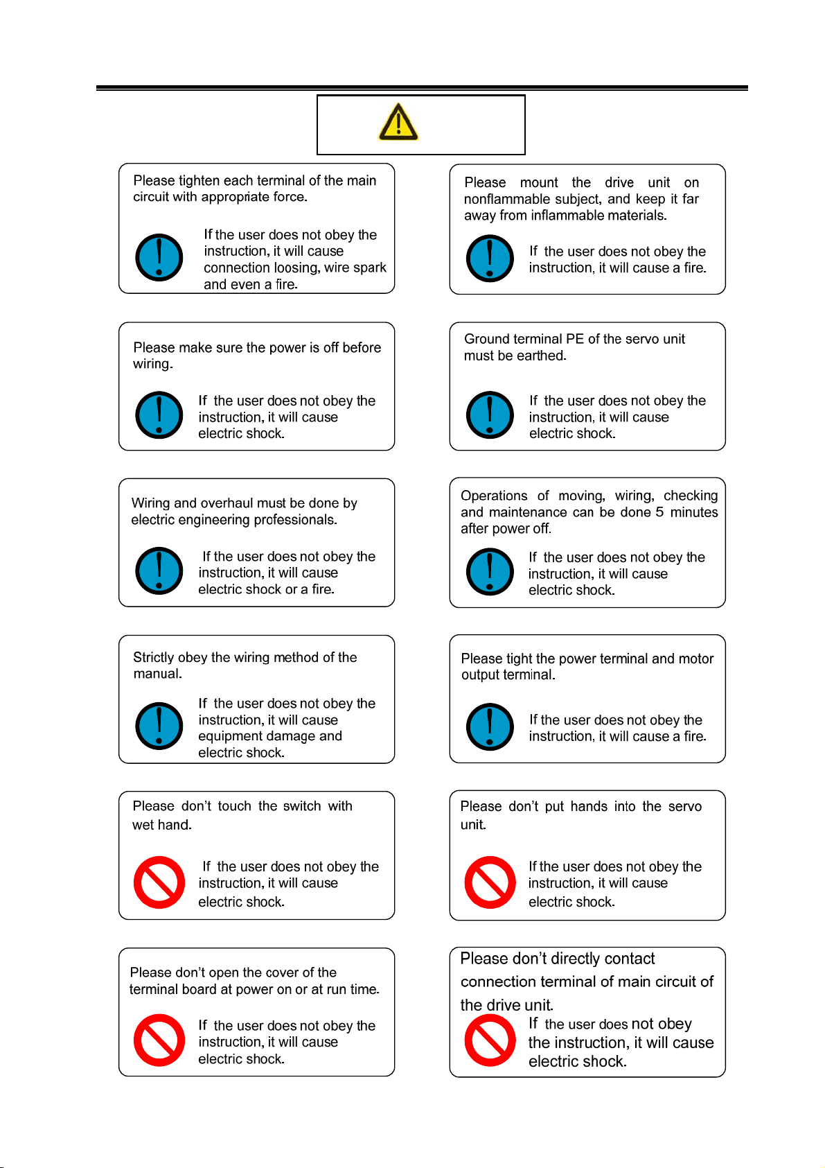
Danger
If the motor operates incorrectly, it will cause damage or death.
If the motor operates incorrectly, it will cause medium or slight
injury, even property loss.
Caution
If this label is not noticed, unexpected result and situation will
Note
Remind important requirements and instructions to user during the
operation.
occur.
II
It indicates prohibition (mustn’t do)
It indicates forced execution (must do)
Page 3
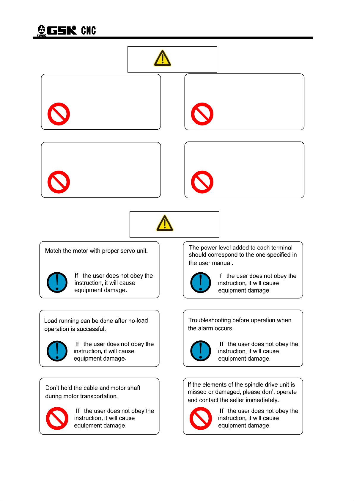
Cautions
Danger
III
Page 4
DAT Series AC Servo Drive Unit User Manual
Note
The drive unit may startup when the power is
recovered, the user don’t operate the shaft
device of the servo motor.
If the user does not obey the
instruction, it will cause
personal injury.
Don’t put the cable on sharp edge. Don’t
make the cable bear heavy load or tension.
If the user does not obey the
instruction, it will cause
electric shock, trouble or
damage.
Caution
Don’t prevent heat diffusion or put object
on radiator fan or radiator.
If the user does not obey the
instruction, it will cause
damage or a fire.
When removing the cover on the terminal
board, the user don’t operate drive device
during power is on.
If the user does not obey the
instruction, it will cause
electric shock.
IV
Page 5
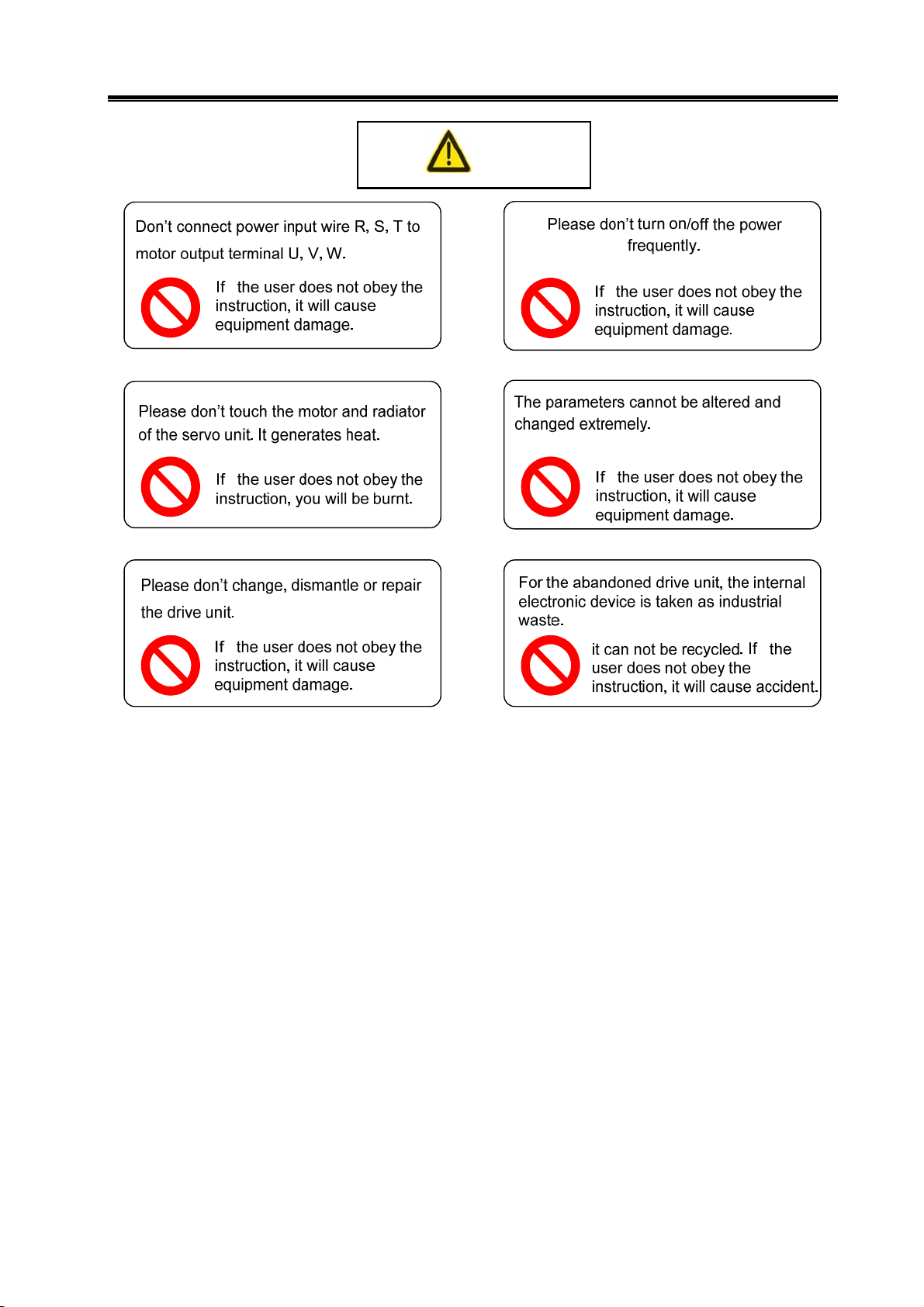
Cautions
Caution
V
Page 6

DAT Series AC Servo Drive Unit User Manual
Safety responsibility
Manufacturer Responsibility
——Be responsible for the danger which should be eliminated and/or controlled on
design and configuration of the provided servo unit and accessories.
——Be responsible for the safety of the provided servo unit and accessories.
——Be responsible for the provided information and advice for the users.
User Responsibility
——Be trained with the safety operation of servo unit and familiar with the safety
operation procedures.
——Be responsible for the dangers caused by adding, changing or altering to the
original servo unit and the accessories.
——Be responsible for the failure to observe the provisions for operation, adjustment,
maintenance, installation and storage in the manual.
This manual is kept by final user.
We are full of heartfelt gratitude to you for supporting us in the use of GSK’s
products.
VI
Page 7

Contents
contents
CHAPTER 1 PRODUCT INTRODUCTION .........................................................................................1
1.1 Basic Knowledge .................................................................................................................1
1.2 Confirmation of the Arrived Goods.......................................................................................6
1.2.1 Instruction of Servo Motor Model ...............................................................................6
1.2.2 Instruction of Servo Motor Models Unit......................................................................7
1.2.3 Appearance of servo unit ...........................................................................................8
1.3 Technical Specifications ..................................................................................................10
1.3.1 Servo motor technical specifications........................................................................10
1.3.2 Technical Specification of Servo Unit ......................................................................13
1.4 Order instruction ..............................................................................................................15
1.4.1 Order model example ..............................................................................................15
1.4.2 Standard Products Accessories...............................................................................17
CHAPTER 2 INSTALLATION ........................................................................................................19
2.1 Servo Motor .......................................................................................................................19
2.1.1 Mounting Dimension of the Servo Motor..................................................................19
2.1.2 Servo Motor Installation ...........................................................................................21
2.2 Servo Unit ..........................................................................................................................22
2.2.1 Installation Dimension..............................................................................................23
2.2.2 Mounting Interval .....................................................................................................24
Chapter 3 CONNECTION.................................................................................................................25
3.1 Connection of Peripherals..................................................................................................26
3.2 Terminal Connection of Main Circuit ...................................................................................30
3.2.1 Terminal Connection of Servo Unit ..........................................................................30
3.2.2 Instructions for Servo Motor Interface......................................................................32
3.3 Connection of Control Signal .............................................................................................33
3.3.1 Definition of Pin CN1 of DAT Series Products .........................................................33
3.3.2 Input of Speed Command ........................................................................................35
3.3.3 Input of Position Command......................................................................................36
3.3.4 Switching Value Input ..............................................................................................39
3.3.5 Output of Switch Value ............................................................................................41
3.4 Connection of Feedback Signal .........................................................................................44
3.4.1 Introductions for CN2 of DAT2000...........................................................................44
3.4.2 Introductions for CN2 OF DAT2000C ......................................................................45
3.4.3 Connection to Encoder Signal of the Motor .............................................................46
3.5 GSKLink Communication Function ....................................................................................48
3.6 Examples for Different Working Mode ...............................................................................50
3.6.1 Speed Mode Wiring of DAT2000 Series Products ...................................................50
3.6.2 Position Mode Connection of DAT2000 Series Products.........................................51
3.6.3 Speed Mode Connection of DAT2000C Series Products ........................................52
3.6.4 Position Mode Connection of DAT2000C Series Products ......................................53
CHAPTER 4 DISPLAY AND OPERATION.......................................................................................54
VII
Page 8

DAT Series AC Servo Drive Unit User Manual
4.1 Operation Panel.................................................................................................................54
4.2 Display Menu.....................................................................................................................54
4.3 State Monitoring.................................................................................................................55
4.4 Parameter Setting.............................................................................................................. 59
4.5 Parameter Management ....................................................................................................60
CHAPTER 5 DEBUGGING AND OPERATION .............................................................................62
5.1 Manual and Jog operation .................................................................................................63
5.1.1 Manual Operation ....................................................................................................64
5.1.2 Jog Operation ..........................................................................................................65
5.2 Speed mode operation ......................................................................................................66
5.2.1 External analog voltage command ..........................................................................66
5.2.2 Internal digital command..........................................................................................69
5.3 Position Mode Operation ...................................................................................................71
Chapter 6 FUNCTION DEBUGGING............................................................................................. 73
6.1 Fundamental performance parameter debugging illustration.............................................73
6.2 Application of brake releasing signal .................................................................................75
6.3 The switchover of motor rotating direction .........................................................................79
6.4 Output of position feedback signal..................................................................................... 80
6.5 Function Debugging of Position Mode ...............................................................................82
6.5.1 Position Command E-gear Ratio .............................................................................82
6.5.2 Position arrival signal (COIN).............................................................................83
6.5.3 Pulse deviation zero clearing(CLE)..................................................................... 84
6.5.4 Pulse command inhibition (INH).........................................................................84
6.6 Function debugging under speed mode ............................................................................84
6.6.1 Adjustment of analog command ..............................................................................84
6.6.2 Speed arrival signal
(COIN) .................................................................................85
6.6.3 Zero speed clamping(ZSL) ................................................................................. 86
CHAPTER 7 PARAMETERS .........................................................................................................87
7.1 Parameter List......................................................................................................................87
7.2 Parameter Description..........................................................................................................89
CHAPTER 8 ABNORMALITIES AND REMEDIES ........................................................................98
8.1 Abnormalities Caused by Misuse .........................................................................................98
8.2 Alarms and Remedies ........................................................................................................100
8.3 Inspection and Maintenance ..............................................................................................105
APPENDIX A MODEL CODE PARAMETERS AND FEED SERVO MOTOR TABLE................. 106
APPENDIX B PERIPHERAL EQUIPMENTS ............................................................................... 108
B. 1 External Braking Resistor (Optional).................................................................................108
B. 2 Circuit Breaker and Contactor (Necessary) ......................................................................109
B.3 Three-Phase AC Filter (Recommended)............................................................................ 110
B.4 Isolation Transformer (Necessary).....................................................................................110
APPENDIX C VERSION UPGRADE INSTRUCTION .....................................................................114
VIII
Page 9
Chapter 1 Product Introduction
CHAPTER 1 PRODUCT INTRODUCTION
1.1 Basic Knowledge
¾ Basic principle of AC servo drive device
The AC servo drive unit consists of AC servo unit and AC servo motor (three-phase
permanent magnet synchronous servo motor, hereafter referred to as the servo motor).
Approximate sine wave current with 120° phase difference (namely: DC—AC) are generated in
three-phase stator winding of the servo motor through controlling on/off of the power switch tube
after three-phase alternating current is rectified to direct current by the servo unit (namely:
AC—DC). Rotary magnetic field is formed by the sine wave current and the rotor of the servo
motor is made of rare earth permanent materials that with fine anti-degaussing property,
therefore, the interaction between the field of motor rotor and rotary field generates
electromagnetic torque to rotate the rotor. The higher the current frequency flowing through the
motor winding is, the faster speed will be. The bigger the current amplitude flowing through the
motor winding is, the bigger the output torque (Torque=force × arm length of the force) will be.
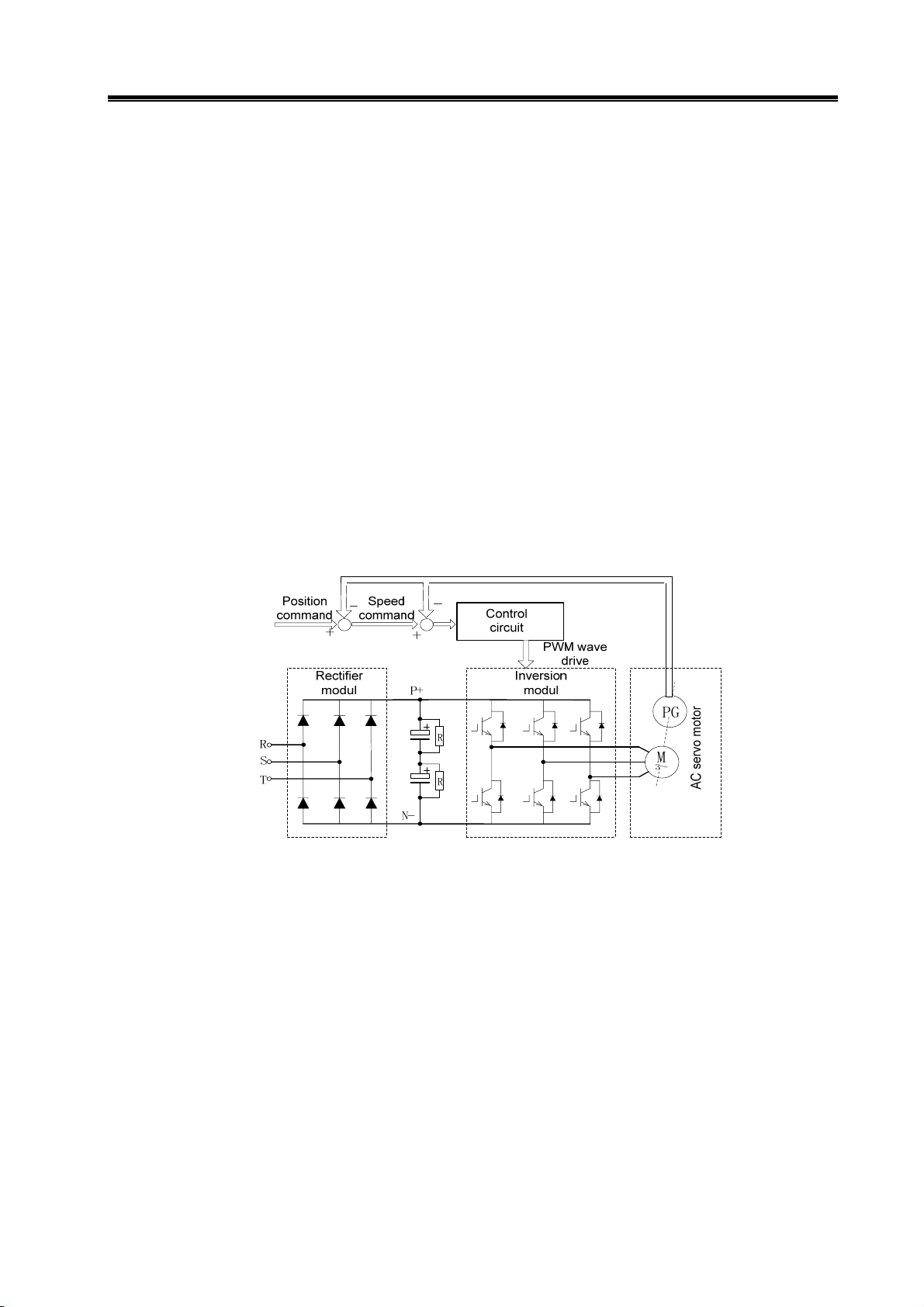
The diagram of main return current, see Fig. 1-1, PG in the figure represents encoder.
Fig.1-1 Main return current diagram of the AC servo drive unit
¾ Basic configuration of AC servo drive device
The servo unit receives the speed (or position) command from a control unit(PC)like
computerized numerical control system (CNC) to control the frequency and magnitude of the
motor winding current, and make the speed (or rotor angle) of motor rotor approach to the speed
(or position) command value. The deviation between the actual value of motor rotor speed (or
rotor angle) and the command value is obtained through the feedback signal from the encoder.
In addition, the servo unit constantly adjusts frequency and magnitude of the motor winding
current to make the deviation between the actual value of motor speed (or rotor anger) and the
command value within a required range. The basic configuration of the servo system is shown in
Fig 1-2.
1
Page 10
DAT Series AC Servo Drive Unit User Manual
setting
CNC
equipment
+
-
Spindle servo drive equipment
Control
unit
Power drive unit
Feedback
check
Motor
Fig.1-2 Basic configuration of AC servo drive device
¾ General concept of control
¾ Control: The process of making the property (eg. Speed) of the object (eg. Servo motor) get
or close to the predicted value is called control. The forementioned object is called controlled
object. Controlled quantity (Variable): The property of the controlled object. Control unit
(controller): The device to achieve control. Setting: The predicted value (command value) of the
controlled quantity that is received by the control unit. Feedback: The controlled quantity is taken
as input of the controller to affect itself. Feedback device: The device to detect the controlled
quantity. According to the vary direction of controlled quantity and setting to the controller output,
the feedback is divided into positive feedback (the same direction) and negative feedback
(opposite direction). Control system consists of the controller used to achieve the controlled
quantity control, the controlled object and the feedback device. The drive device is divided into
closed-loop control and open-loop control according to the presence and absence of feedback
device, and the position of feedback unit .The closed loop introduced in this manual are all
closed loop of negative feedback.
In the AC servo drive unit introduced by this manual, servo unit is a controller, the servo
motor is controlled object, the motor speed (or rotor angle) is a controlled quantity, the encoder of
the servo motor is a feedback device. The actual speed is detected by the encoder and it is used
to speed control to achieve speed feedback. Therefore, the AC servo drive unit belongs to closed
loop control system.
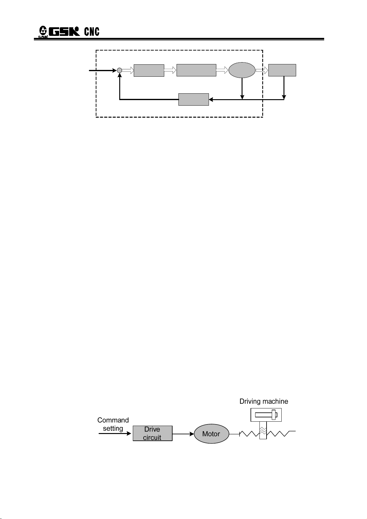
z Open loop control: There is no feedback device in the control system, and the actual value
of the controlled quantity does not affect the controller output. Example: Drive unit of step motor.
After output current phase sequence of servo unit of step motor is changed, the rotation of rotor
of the step motor should vary with it. Because the step motor are not usually installed speed or
position feedback device, the rotation of motor rotor may not vary accurately with the changing of
the current phase sequence, which causes so-called “step out”.
Open loop control is shown in Fig. 1-3.
Driving
machine
Fig. 1-3 Open loop control
2
Page 11
Chapter 1 Product Introduction
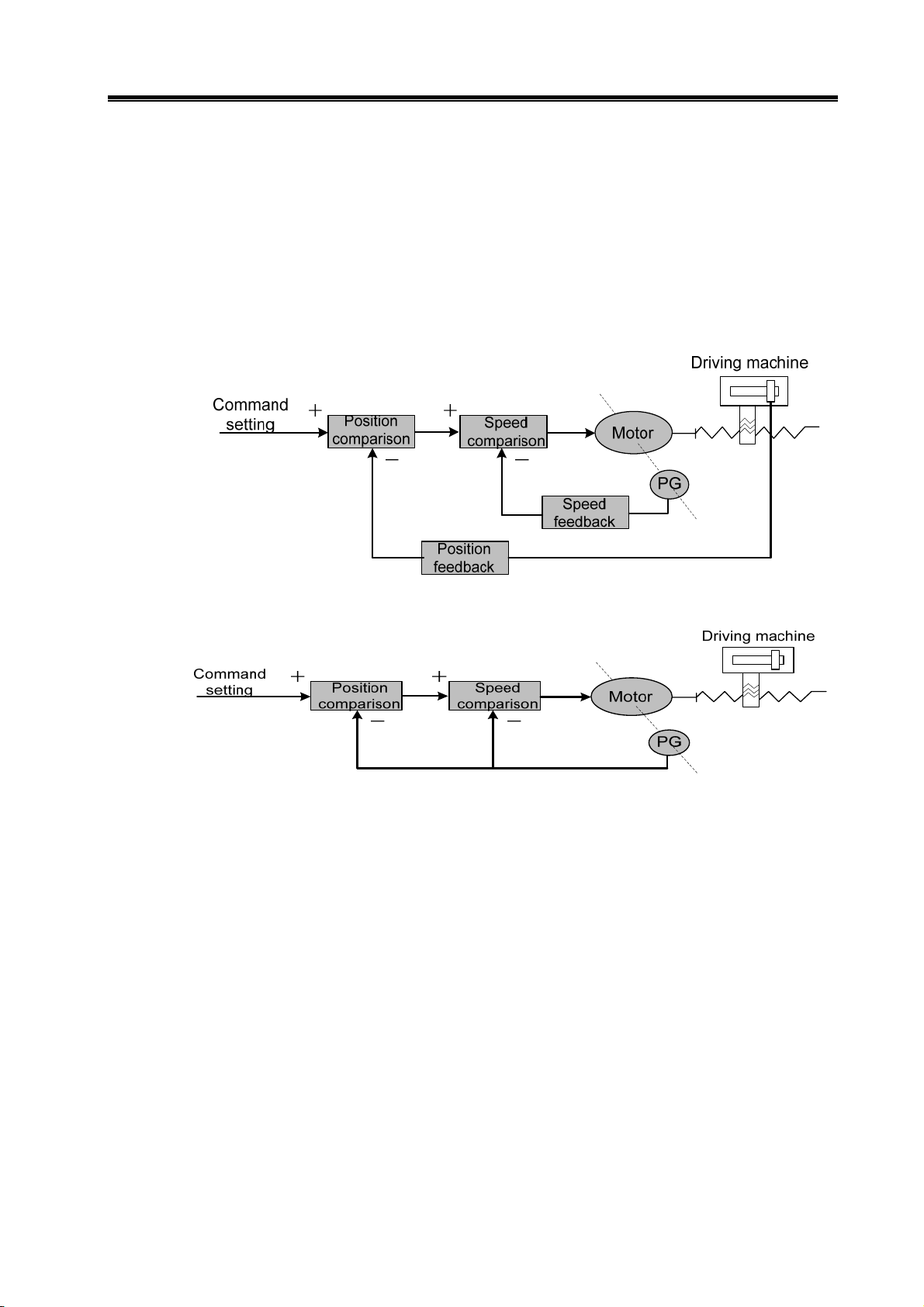
z Closed loop control: The controlled quantity of the control system is detected by feedback
device and is output to the controller. This process affects the output of the controller and then
changes the controlled quantity. According to the detection point of the feedback device, the
closed loop control id divided into entirely closed loop control and semi closed loop control.
Entirely closed loop control (Fig. 1-4): The controlled quantity is detected directly by the feedback
device and it is used for feedback. Mechanical position is used as controlled quantity, grating
ruler fixed on the machine as position feedback device, and the encoder of the servo motor is
taken as a speed feedback device, realizing the entirely closed loop control of machine position.
If the grating ruler is not fixed, the encoder of the servo motor is used as speed feedback device
(Fig. 1-5), therefore, this is a semi-closed loop control of a mechanical position.
Fig. 1-4 Full-closed loop control
Fig. 1-5 semi-closed loop control
z PID Control: also called PID adjustment, is a common algorithm the controller adopted to
mathematically deal with input data (setting, feedback). P stands for proportional, which means
the input of the controller is to be linearly proportional to the output, the larger the adjustment
coefficient is, the more sensitive the system will react and smaller the error is (can not completely
eliminated), however, over larger adjustment coefficient will result in system oscillation and
instability. I stands for integral, means time integral of system input affects the output (input
gradually affects output), the larger the integration time constant is, the more stable the system
will be, which can eliminate steady-state error but slows system response at the same time. D
stands for differential, which means input differential (slope of input change) affects output,
differential control may predict deviation and produce advanced correction action to decrease
tracking error and improve dynamic performance; while over large differential coefficient will also
result in system oscillation and instability. Along with the adjustment of PID control coefficient at
specific control system, the proportional, integral and differential adjustment are mutually
affected to make a balance between system reaction speed, control accuracy and stability. As
differential adjustment is prone to produce impact and oscillation, the servo system introduced in
this manual adopts PI adjustment, that is, proportional and differential adjustment.
3
Page 12
DAT Series AC Servo Drive Unit User Manual
¾ Concepts of servo control
There are three basic control models in servo system: location control, speed control and
torque control. The system chart is shown in Fig. 1-6.
z Position control: set the direction and angle of motor rotation through digital pulse or data
communication, the motor rotor controlled by servo unit will rotate to the corresponding angle in
accordance with the preset direction. The rotary angle (position) and speed are both controllable.
z Speed control: set the direction and angle of motor rotation through analog voltage or data
communication, the motor rotor controlled by servo unit will rotate in accordance with the set
direction and speed.
z Torque control: set the value and direction of the motor output torque through analog
voltage or data communication, the servo unit controls the motor rotor’s rotation direction and the
value of output torque.
The servo device introduced in this manual does not receive signals set by torque at present
and the torque control operational mode is not available for the time being.
+
Command
position
Position
controller
Position
adjustment
-
Position
feedback signal
Speed
controller
+ Speed
adjustment
-
Speed feedback
signal
+
Current
controller
Current
adjustment
-
Current feedback
signal
Power
amplification
Motor
PG
Fig. 1-6 Three-loop control diagram
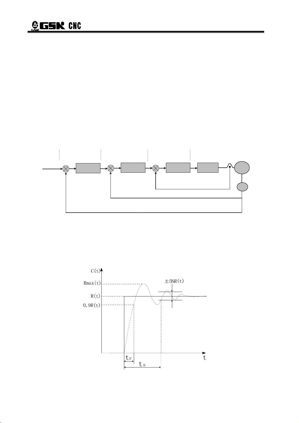
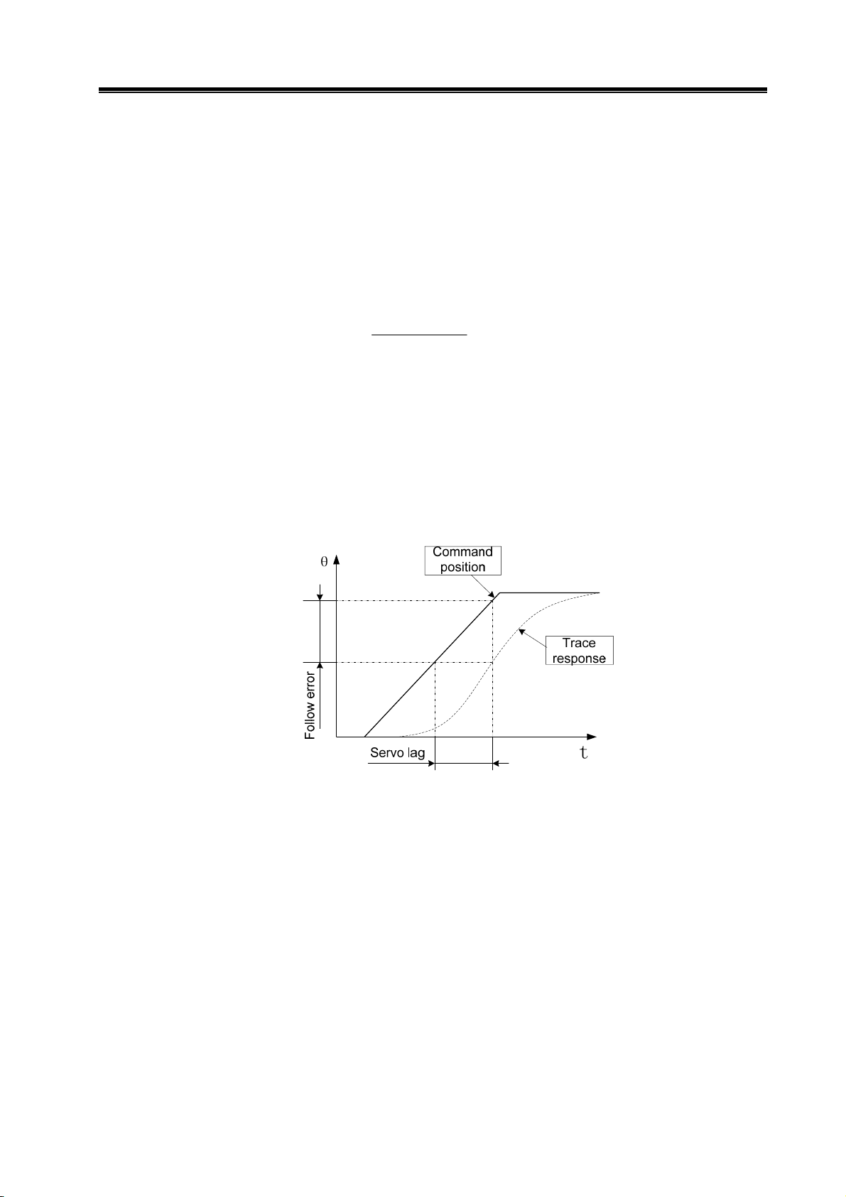
¾ Servo performance index
Servo dynamic reaction characteristics: refers to the reaction speed, dynamic control error
and stable control error of the servo system with set signal or load change. Fig. 1-7 indicates
reaction characteristics of the servo system set with step signals (solid line represents the setting
signal and dashed line represents the output signal of the servo system).
Fig. 1-7 Servo dynamic reaction curve
4
Page 13
Chapter 1 Product Introduction
Rise time tr: the length of time of the speed quantity rise for the first time from zero to 90% of a stable
value R (t), which shows the rapidity of dynamic reaction.
Adjustment time t
error interval which is used to measure the whole adjustment tempo of the device. The allowed
interval refers to plus or minus 5% of the stable value proximal to the step reaction curve stable
value R (t).
Overshoot σ:The ratio between the maximum D-value that the rotation output quantity overpasses
the stable value(Rmax(t)- R (t))and the stable value R (t), which reflects the relative stability of
the servo device and expressed as percentages, i.e.:
Steady-state error: the difference between the expected output steady-state value and the practical
output value after the system rotation speed turned into stable.
Servo static performance: Stability is the most important issue of the servo control system. Servo
static performance index, mainly the position accuracy, refers to deviation degree between the
practical state and expected state when the system transient process comes to cease. Not only
errors from the position measurement device and from the system will affect servo steady-state
accuracy, but the internal structure and parameters of the system can also matter. Fig.1-8 shows
the position servo static curve.
: The minimum time needed to make the reaction curve reach but not exceed
s
)()(
−
σ
(%)
max
=
tRtR
)(
tR
%100
×
Fig. 1-8 Position servo static curves
Tracking error: The difference between the movable position of the workbench requested by the
command signals (commanding position) and the practical movable position, i.e., tracking error
equals to the value of commanding position minus the value of practical position.
Servo rigidity: servo system’s capability to resist the position deviation resulted from load
interference.
5
Page 14
DAT Series AC Servo Drive Unit User Manual
1.2 Confirmation of the Arrived Goods
Please promptly inspect the received goods in accordance with the following items, any question,
please feel free to contact suppliers or our company.
Inspected Items Notes
Check and confirm if the servo units
and servo motors are the ordered.
Accessories complete or not
Damaged or not in transport
Screw loose or not
Please check by the nameplates on the servo units
and servo motors
Please check accessories according to packing list,
any unmatched ones, refer to order instruction 1.4.
Check the general appearance of goods to ensure
products intact and with no damage.
Please check if there is any screw loose with
screwdrivers.
1. Damaged AC servo unit or the ones without integrated parts can not be installed.
2. AC servo unit should be matched with servo motor with proper property.
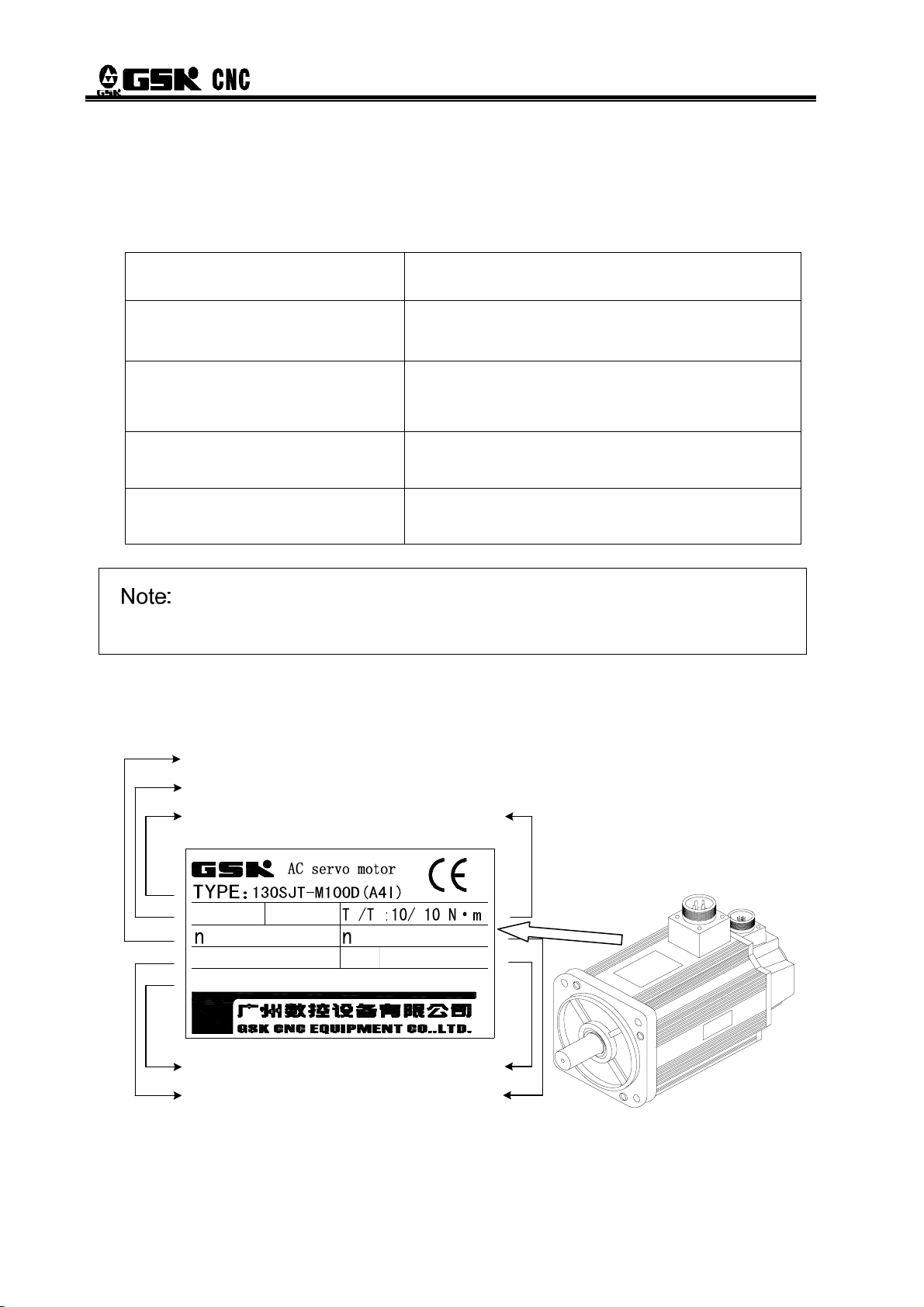
1.2.1 Instruction of Servo Motor Model
Rated speed
Rated voltage and rated current
Servo motor model
交流伺服电动机
N
U :220V
N
: 2500r/min
S/N:
Product No.
Class of Insulation
N
I :10A
081016100D0000107H
max
IP65INS.CLASS: B
Grade of protection
Encoder lines
Rated torque
NS
: 3000 r/min
M: 17 bit
Max speed
Fig. 1-9 Instruction of servo motor models:
6
Page 15

Chapter 1 Product Introduction
130 SJT
Machine model
AC synchonic servo motor
M:Photoelectric encoder
Non:Non-electricity-breaking brake
Z:With-electricity-breaking brake
Zero-speed torque
150: 15N·m
Rated
rotation
speed
#1:Working power of electricity-breaking brake: DC(0.9~1.1)×24V, interface: triax socket, 1,2
pin are power terminals (have no polarity), 3 pin is the earth terminal. When the 1 and 2 pin plug
in power, the electricity-breaking brake doesn’t work, while when the power is disconnected, it
will brake and the operating time is less or equal to 0.1s.
#2:A three-digital number “150” is used to show its value: 150×10
A:1000 r / min
B:1500
C:2000
D:2500
E:3000
2
r/min
r/min
r/min
r/min
-
M
Z
150 D(A□Y□X
□
)
Non:Aviation sockettype
X:Cable direct type
Shaft or installation config.#3
Non:Standard shaft
Y□:Special ballpoint shaft
Z□:Special cone shaft
S□:Stepping motor installation config.
Encoder type
A or None:
A2:Increment type 5000 p/r
A3:Increment split-type 5000 p/r
A4:Absolute type 17bit
A41:Danaher multi-circle 17bit absolute type
A4S1:Danaher single-17bit absolute type
Increment type 2500 p/r
-1
=15, unit: N.m.
#3:‘□’ is a numeric codes, please refer to the installation outline drawing of the motor for the
special shaft represented by a certain number.
1.2.2 Instruction of Servo Motor Models Unit
Nameplate examples:
Motor model corresponded to factory parameter of the drive unit
Drive unit order model
Digital AC servo drive unit
DAT2075C
Version: Model :
V1.05
Adapted motor:130SJT-M150D(A4
Power:3-phase 220V
SN:E03DN00088
Date:2009/3
Tel.020-81986247 Fax.81993683
)
Software version
of Drive unit
Production date
of drive unit
Production No. of drive unit
Power of drive unit
7
Page 16
DAT Series AC Servo Drive Unit User Manual
DAT 2 050
130
-
C
SJT M-
IPM module nominal current
Input power grade:2:AC220V
Product model code
150 D
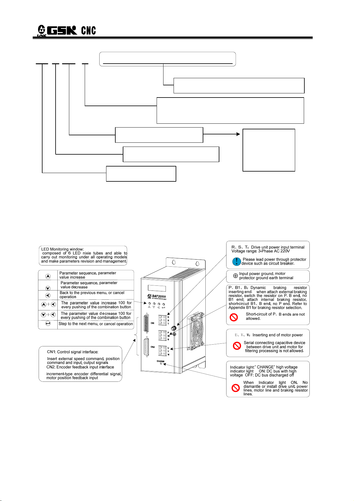
1.2.3 Appearance of servo unit
z Appearance of DAT2030 and DAT2050
A □ Y □X □)
(
Matching AC servo motor model (omit if no matching)
Communications Mode:
C: GSKLink serial communications
None: No serial communications function
030:30A;
050:50A;
075:75A;
100:100A。
8
Page 17

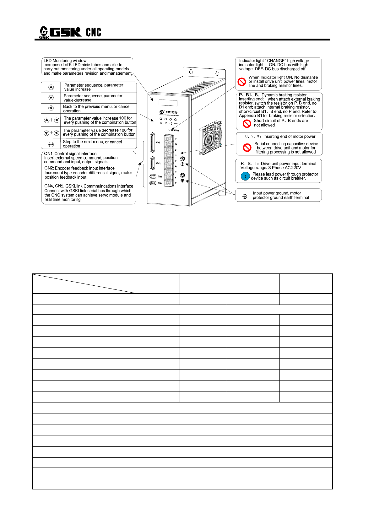
z Appearance of DAT2030C and DAT2050C
LED Monitoring window:
composed of 6 LED nixie tubes and able to
carry out monitoring under all operating models
and make parameters revision and management.
Parameter sequence, parameter
value increase
Parameter sequence, parameter
value decrease
Back to the previous menu, or cancel
operation
The parameter value increase 100 for
every pushing of the combination button+
The parameter value decrease 100 for
+
every pushing of the combination button
Step to the next menu, or cancel operation
CN1: Control signal interface:
Insert external speed command, position command
and input, output signals
CN2: Encoder feedback input interface
Increment-type encoder differential signal, motor
position feedback input
CN4, CN5, GSKLlink Commnuincations Interface
Connect with GSKLlink serial bus through which
the CNC system can achieve servo module and
real-time monitoring.
z Appearance of DAT2075 and DAT2100
Chapter 1 Product Introduction
R、S、T:Drive unit power input terminal
Voltage range: 3-Phase AC 220V
Please lead power through protector
!
device such as circuit breaker.
Input power ground, motor protector
ground earth terminal
P、B1、B:Dynamic braking resistor inserting
end: when attach external braking resistor,
switch the resistor on P. B end, no B1 end;
attach internal braking resistor, short-circuit
B1、B end, no P end. Refer to Appendix B1 for
braking resistor selection.
Indicator light:” CHANGE” high voltage
indicator light ON: DC bus with high voltage
OFF: DC bus discharged off
Short-circuit of P、B ends are
not allowed.
U、V、W:Inserting end of motor power
Serial connecting capacitive device
between drive unit and motor for
filtering processing is not allowed.
When Indicator light ON, No dismantle
or install drive unit, power lines, motor
line and braking resistor lines.
9
Page 18
DAT Series AC Servo Drive Unit User Manual
z Appearance of DAT2075C,DAT2100C
1.3 Technical Specifications
1.3.1 Servo motor technical specifications
Table 1-1 Principle Technical Parameters of 80SJT Series Motor
Model
Project
Rated Voltage(kW)
Pole-pairs 4
Rated Current(A)
Zero-speed Torque(N·m)
Rated Torque(N·m)
Maximum Torque (N·m)
Rate Rotary speed(r/min)
Maximum Rotary speed(r/min)
Moment of Inertia(kg·m2)
Weight(kg)
80SJT-M024C
(A□)
0.5 0.75 0.66 1.0
3 4.8 5 6.2
2.4 2.4 3.2 3.2
2.4 2.4 3.2 3.2
7.2 7.2 9.6 9.6
2000 3000 2000 3000
2500 4000 2500 4000
0.83×10
2.8 2.9 3.4 3.5
80SJT-M024E
(A□)
-4
0.83×10⁻⁴ 1.23×10⁻⁴ 1.23×10⁻⁴
80SJT-M032C
(A□)
80SJT-M032E
(A□)
Insulation Grade
Oscillation Grade
Protection Grade
Installation Type
character of service
electricity-breaking brake Not available
Adaptive Encoder
10
IP65(GB 4208—2008/IEC 60529:2001,GB/T 4942.1—2006)
IMB5(Flange installation)(GB/T 997—2008 / IEC 60034-7:2001)
S1(Continuous duty)(GB 755—2008)
Increment-type 2500 p/r,5000 p/r etc,absolute encoder17bit
F(GB 755—2008)
R(GB 10068—2008)
single-circuit or multi-coil。
Page 19

Chapter 1 Product Introduction
Table 1-2 Principle Parameters of 110SJT Series, 130SJT Series Motor
Model
Project
Rated Voltage(kW)
Pole-Pairs 4
Rated Current (A)
Zero-speed Torque
(N·m)
Rated Torque (N·m)
Maximum Torque (N·m)
Rated Rotary speed
(r/min)
Maximum Rotary speed
(r/min)
Moment of Inertia
(kg·m
2
)
Weight(kg)
Weight of motor with
electricity-breaking
brake(kg)
110SJT-M
040D(A□)
110SJT-M
040E(A□)
110SJT-M
060D(A□)
110SJT-M
060E(A□)
130SJT-M
040D(A□)
130SJT-M
050D(A□)
1.0 1.2 1.5 1.8 1.0 1.3
4.5 5 7 8 4 5
4 4 6 6 4
4 4 6 6 4
12 10 12 12 10
5
5
12.5
2500 3000 2500 3000 2500 2500
3000 3300 3000 3300 3000 3000
0.68×10
-3
0.68×10
-3
0.95×10
-3
0.95×10
-3
1.1×10⁻³ 1.1×10⁻³
6.1 6.1 7.9 7.9 6.5 6.5
7.7 7.7 9.5 9.5 8.1 8.1
Insulation Grade
Oscillation Grade
Protection Grade
Installation Type
Character of Service
Adaptive Encoder
Table 1-2 Principle Parameters of 110SJT Series, 130SJT Series Motor(continue)
Model
Project
Rated Voltage(kW)
Pole-Pairs 4
Rated Current (A)
Zero-speed Torque
(N·m)
Rated Torque (N·m)
B(GB 755-2008)
R(GB 10068-2008)
IP65(GB/T4942.1-2006)
IMB5(Flange Installation)(GB/T 997-2008 / IEC 60034-7:2001)
S1(Continuous Duty)(GB 755-2008)
Increment-type 2500 p/r,5000 p/r etc,absolute encoder17bit single-circuit
or multi-coil。
130SJT-M
060D(A□)
1.5 1.88 1.5 2.5 2.3
130SJT-M
075D(A□)
130SJT-M
100B(A□)
130SJT-M
100D(A□)
130SJT-M
150B(A□)
130SJT-M
150D(A□)
3.9
6 7.5 6 10 8.5 14.5
6 7.5 10 10 15 15
6 7.5 10 10 15 15
Maximum Torque (N·m)
18 20 25 25 30 30
11
Page 20

DAT Series AC Servo Drive Unit User Manual
Rated Rotary speed
(r/min)
Maximum Rotary speed
(r/min)
Moment of Inertia(kg·m2)
Weight(kg)
Weight of motor with
electricity-breaking brake
(kg)
Insulation Grade
Oscillation Grade
Protection Grade
Installation Type
Character of Service
Adaptive Encoder
2500 2500 1500 2500 1500 2500
3000 3000 2000 3000 2000 3000
1.33×10
-3
1.85×10
-3
2.42×10
-3
2.42×10
-3
3.1×10⁻³ 3.6×10⁻³
7.2 8.1 9.6 9.7 11.9 12.7
10.1 11 12.5 12.6 14.8 15.6
B(GB 755-2008)
R(GB 10068-2008)
IP65(GB/T4942.1-2006)
IMB5(Flange Installation)(GB/T 997-2008 / IEC 60034-7:2001)
S1(Continuous Duty)(GB 755-2008)
Increment-type 2500 p/r,5000 p/r etc,absolute encoder17bit single-circuit or
multi-coil
Model
Project
Rated Voltage(kW)
Pole-Pairs 3
Rated Current (A)
Zero-speed Torque (N·m)
Rated Torque (N·m)
Maximum Torque (N·m)
Rated Rotary speed(r/min)
Maximum Rotary speed
(r/min)
Moment of Inertia(kg·m2)
Weight(kg)
Weight of motor with
electricity-breaking brake
(kg)
Insulation Grade
Oscillation Grade
Protection Grade
Installation Type
Character of Service
Adaptive Encoder
Table 1-3 Principle Parameters of 175SJT Series Motor
175SJT-M
180B(A□)
175SJT-M
180D(A□)
175SJT-M
220B(A□)
175SJT-M
220D(A□)
175SJT-M
300B(A□)
175SJT-M
300D(A□)
2.8 3.8 3.5 4.5 3.8 6
15 16.5 17.5 19 19 27.5
18 18 22 22 30 30
18 14.5 22 17.6 24 24
36 29 44 35.2 48 48
1500 2500 1500 2500 1500 2500
2000 3000 2000 3000 2000 3000
6.5×10
-3
6.5×10
-3
9.0×10⁻³ 9.0×10⁻³ 11.2×10⁻³ 11.2×10
22.8 22.9 28.9 29.2 34.3 34.4
28.4 28.5 34.5 36.8 42 42.1
F(GB 755-2008)
R(GB 10068-2008)
IP65(GB/T4942.1-2006)
IMB5(Flange Installation)(GB/T 997-2008 / IEC 60034-7:2001)
S1(Continuous Duty)(GB 755-2008)
Increment-type 2500 p/r,5000 p/r etc,absolute encoder17bit
single-circuit or multi-coil。
-3
12
Page 21

Mechanical Properties of Servo Motor
1.3.2 Technical Specification of Servo Unit
Servo unit model
Rated current of
adaptive servo current
(A)
DAT2030
DAT2030C
<6
DAT2050
DAT2050C
6~10.5 11~21 22~28
Chapter 1 Product Introduction
DAT2075
DAT2075C
DAT2100
DAT2100C
Dimension(mm)
(width*height*depth)
Main power
speed regulation ratio
Speed fluctuation ratio
Speed frequency
response
Position accuracy
Work mode
Internal speed pattern
External speed pattern
Position pattern
263×115×197 300×105×240
3-phase AC(0.85~1.1)×220 V, 50Hz/60Hz
5000:1
DAT2000 adaptive to 5000p/r increment encoder, <0.03%;
DAT2000C adaptive to 17bit absolute encoder,<0.01%;
≥300Hz
DAT2000 adaptive to 2500p/rspeed regulation ratio, Position error:
±0.036°
DAT2000 adaptive to 5000p/rspeed regulation ratio, Position error:
±0.018°
DAT2000C adaptive to 17bit absolute encoder,Position error:±0.005°
As manual operation, jog, internal speed, external speed, position, zero
setting etc.
Servo motor operates at the 4-stage speed set in accordance with
parameters and selected by input signals.
Servo motor operated at the speed corresponding to VCMD input
(-10V~+10V or 0V~+10V) analog voltage).
13
Page 22

Position feedback input
position feedback
output
DAT Series AC Servo Drive Unit User Manual
Rotary angle of servo motor is controlled according to the pulse quantity
of position command and the rotary speed determined by the pulse
frequency of position command.
Position command mode: pulse plus direction, CCW pulse/CW pulse,
A/B two phase orthogonal pulse
Maximum pulse frequency: 1MHz
Command pulse frequency multiplication ratio and frequency
demultiplication: 1~32767
1
Position command electric gear ratio
~50
50
With DAT2000 standard adaptive increment type encoder as the
position feedback input, A/B/Z/U/V/W differential signal , encoder
resolution ratio: 2500 pixels or 5000 pixels.
With DAT2000C standard adaptive absolute encoder as the position
feedback input, i.e. 17bit absolute encoder, 12bit circles of power-down
memory。
Carry out frequency division processing to the pulse data from
electromotor encoder (PG or pulse generator) in drive unit and output
them to upper computer through CN1 in accordance with the preset
pulse number so as to realize function such as the positional
closed-loop control of upper computer.
Communications bus
10 input points as servo enabling, alarming elimination, CCW
Input signal
Output signal
Protection function
Operation and display
braking mode
CCW indicates the main drive shaft of motor installation plane rotates counterclockwise
when you see it from the shaft extension direction (CCW-Counter Clockwise).
CW indicates the main drive shaft of motor installation plane rotates clockwise when you
see it from the shaft extension direction (CW- Clockwise).
prohibition, CW prohibition, Zero-speed clamping, internal speed
option1,internal speed option 2,CCW torque limitation, CW torque
limitation, general input etc.
7 output points as S-RDY, servo alarming, position arrival/speed arrival,
band-type brake release, zero-speed output, Z pulse(encoder zero
point), general output, etc.
With protection functions as overvoltage, undervoltage, overcurrent,
overload, overspeed, position deviation, drive abnormality, encoder
abnormality, etc.
4 buttons, manual operation, jog as well as parameter revision, setting,
writing-in and back-up are available.
6 LEDs which display information as rotary speed, current position,
pulse accumulation, position deviation, motor torque, motor current,
absolute rotor position, input & output signal states.
Dynamic braking, built-in braking resistor (DAT2100 or DAT2100C
excluded) and can attach external braking resistor.
GSKLink Bus(V1.0)
14
Page 23

Chapter 1 Product Introduction
1.4 Order instruction
1.4.1 Order model example
Order model examples of adaptive SJT series servo motor are listed on the following chart:
Principle motor parameters
Order model
DAT2030-05-80SJT-M024C 0.5kW 3 A 2.4 N·m 2000r/min
DAT2030-08-80SJT-M024E 0.75kW 4.8 A 2.4 N·m 3000r/min
DAT2030-07-80SJT-M032C 0.66kW 5 A 3.2 N·m 2000r/min
DAT2050-10-80SJT-M032E 1.0kW 6.2 A 3.2 N·m 3000r/min
DAT2030-10-110SJT-M040D(A2)
DAT2030-10-110SJT-MZ040D(A2)
DAT2050-15-110SJT-M060D(A2)
DAT2050-15-110SJT-MZ060D(A2)
DAT2030-10-130SJT-M040D(A2)
DAT2030-10-130SJT-MZ040D(A2)
DAT2030-13-130SJT-M050D(A2)
DAT2030-13-130SJT-MZ050D(A2)
DAT2050-15-130SJT-M060D(A2)
DAT2050-19B-130SJT-M075D(A2)
DAT2050-15-130SJT-M100B(A2)
DAT2050-25B-130SJT-M100D(A2)
DAT2050-23B-130SJT-M150B(A2)
DAT2075-39E-130SJT-M150D(A2)
DAT2075-28E-175SJT-M180B(A2)
DAT2075-38E-175SJT-M180D(A2)
DAT2075-35-175SJT-M220B(A2)
DAT2075-45-175SJT-M220D(A2)
Rated
Voltage
1.0kW 4.5A 4N·m 2500r/min
1.5kW 7A 6N·m 2500r/min
1.0kW 4A 4N·m 2500r/min
1.3kW 5A 5N·m 2500r/min
1.5kW 6 A 6 N·m 2500r/min
1.9kW 7.5 A 7.5 N·m 2500r/min
1.5kW 6 A 10 N·m 2500r/min
2.5kW 10 A 10 N·m 2500r/min
2.3kW 8.5 A 15 N·m 1500r/min
3.9kW 14.5 A 15 N·m 2500r/min
2.8kW 15 A 18 N·m 1500r/min
3.8kW 16.5 A 18 N·m 2500r/min
3.5kW 17.5 A 22 N·m 1500r/min
4.5kW 19 A 22 N·m 2500r/min
Rated
Current
Zero-speed
Torque
Rated
speed
Encoder
2500p/r
Incremental type
2500p/r
Incremental type
2500p/r
Incremental type
2500p/r
Incremental type
5000p/r
Incremental type
5000p/r
Incremental type
5000p/r
Incremental type
5000p/r
Incremental type
5000p/r
Incremental type
5000p/r
Incremental type
5000p/r
Incremental type
5000p/r
Incremental type
5000p/r
Incremental type
5000p/r
Incremental type
5000p/r
Incremental type
5000p/r
Incremental type
5000p/r
Incremental type
5000p/r
Incremental type
15
Page 24

DAT Series AC Servo Drive Unit User Manual
Principle motor parameters
Order model
DAT2075-38-175SJT-M300B(A2)
DAT2100-60-175SJT-M300D(A2)
DAT2030C-10-110SJT-M040D(A4I)
DAT2030C-10-110SJT-MZ040D(A4I)
DAT2050C-15-110SJT-M060D(A4I)
DAT2050C-15-110SJT-MZ060D(A4I)
DAT2030C-10-130SJT-M040D(A4I)
DAT2030C-10-130SJT-MZ040D(A4I)
DAT2030C-13-130SJT-M050D(A4I)
DAT2030C-13-130SJT-MZ050D(A4I)
Rated
Voltage
Rated
Current
3.8kW 19 A 30 N·m 1500r/min
6.0kW 27.5 A 30 N·m 2500r/min
1.0kW 4.5A 4N·m 2500r/min
1.5kW 7A 6N·m 2500r/min
1.0kW 4A 4N·m 2500r/min
1.3kW 5A 5N·m 2500r/min
DAT2050C-15-130SJT-M060D(A4I) 1.5kW 6 A 6 N·m 2500r/min
DAT2050C-19B-130SJT-M075D(A4I) 1.9kW 7.5 A 7.5 N·m 2500r/min
DAT2050C-15-130SJT-M100B(A4I) 1.5kW 6 A 10 N·m 2500r/min
DAT2050C-25B-130SJT-M100D(A4I) 2.5kW 10 A 10 N·m 2500r/min
DAT2050C-23B-130SJT-M150B(A4I) 2.3kW 8.5 A 15 N·m 1500r/min
DAT2075C-39E-130SJT-M150D(A4I) 3.9kW 14.5 A 15 N·m 2500r/min
DAT2075C-28E-175SJT-M180B(A4I) 2.8kW 15 A 18 N·m 1500r/min
DAT2075C-38E-175SJT-M180D(A4I) 3.8kW 16.5 A 18 N·m 2500r/min
DAT2075C-35-175SJT-M220B(A4I) 3.5kW 17.5 A 22 N·m 1500r/min
DAT2075C-45-175SJT-M220D(A4I) 4.5kW 19 A 22 N·m 2500r/min
DAT2075C-38-175SJT-M300B(A4I) 3.8kW 19 A 30 N·m 1500r/min
DAT2100C-60-175SJT-M300D(A4I) 6.0kW 27.5 A 30 N·m 2500r/min
Zero-speed
Torque
Rated
speed
Encoder
5000p/r
Incremental type
5000p/r
Incremental type
17bit multi-coil
absolute type
17bit multi-coil
absolute type
17bit Multi-coil
absolute type
17bit Multi-coil
absolute type
17bit Multi-coil
absolute type
17bit Multi-coil
absolute type
17bit Multi-coil
absolute type
17bit Multi-coil
absolute type
17bit Multi-coil
absolute type
17bit Multi-coil
absolute type
17bit Multi-coil
absolute type
17bitMulti-coil
absolute type
17bit Multi-coil
absolute type
17bit Multi-coil
absolute type
17bit Multi-coil
absolute type
17bit Multi-coil
absolute type
16
Page 25

Chapter 1 Product Introduction
1.4.2 Standard Products Accessories
Following list shows the standard products accessories which are allocated on the basis that
no special requirement asked by users. If users need other accessories not included in the list,
please contact salesperson or consult our technicians for further information.
DAT2000 series servo unit standard accessories list(allocated per each servo unit)
Order
Type
servo unit
and servo
motor kit
Servo unit
and CNC
Kit(without
servo
motor)
Servo unit,
servo
motor and
CNC Kit
Note: Please mark on the order if you need other length of wire except for the standard 3M.
Accessories Name Quantity Description Note
44DB cellular type plug and
1set CN1 connection plug
plastic box
motor encoder wire 1strip standard length 3M
motor wire 1strip standard length 3M
“Instruction Manual of DAT
Series AC Servo Drive Unit”
RXLG-1500W-10ΩJ braking
resistor
25DB pin-type plug and plastic
1 PCS Accompanying
technical document
1 PCS Only DAT2100 adaptive
to this accessory
1 set CN2 connection plug
welded cable wire
box
“Instruction Manual of DAT
Series AC Servo Drive Unit
RXLG-1500W-10ΩJ braking
resistor
1PC Accompanying
technical document
1PC Only DAT2100 adaptive
to this accessory
motor encoder wire 1strip standard length 3M
motor wire 1 strip standard length 3M
“Instruction Manual of DAT
Series AC Servo Drive Unit
RXLG-1500W-10ΩJ braking
resistor
1PC Accompanying
technical document
1PC Only DAT2100C
adaptive to this
CN1-CNC signals
accessory
are available
CN1-CNC
signals.
connection wires
are available
along with CNC
products
connection wires
are available
along with CNC
products
17
Page 26

DAT Series AC Servo Drive Unit User Manual
DAT2000C Series Servo Unit Standard Accessories List(allocated per each servo unit)
Order
Type
Servo unit
and CNC
Kit(without
servo
motor)
servo unit,
servo
motor and
CNC Kit
DAT Series Selective Accessories
Accessory Name Quantity Description Note
26P high density plug and
plastic box
“Instruction Manual of DAT
Series AC Servo Drive Unit
RXLG-1500W-10ΩJ braking
resistor
1set CN2 connection plug
1 pc Accompanied
technical document
1 pc Only DAT2100C
adaptive to this
CN1-CNC,
GSKLinK signals
connection wire and
terminal socket are
available along with
CNC products
accessory
motor encoder wire 1strip standard length 3M
motor wire 1 strip standard length 3M
“Instruction Manual of DAT
Series AC Servo Drive Unit
RXLG-1500W-10ΩJ braking
resistor
1 pc Accompanied
technical document
1 pc Only DAT2100C
adaptive to this
CN1-CNC,
GSKLinK signals
connection wire and
terminal socket are
available along with
CNC products
accessory
Accessory Name Description Note
Braking resistor
RXLG-300W-30ΩJ
Braking resistor
RXLG-500W-22ΩJ
Power:300W,resistivity: 30Ω; DAT2030
or DAT2030C external selective
Power 500W,resistivity: 22Ω;DAT2050
or DAT2050C external selective
Refer to
Appendix B1
“Outlay Braking
Resistor” for
detailed the
Braking resistor
RXLG-1000W-15ΩJ
4*1.5mm2 BVVB
4*2.5mm2 BVVB
Power 1000W,resistivity:15Ω; DAT2075
or DAT2075C external selective
4-core wire, wire diameter:1.5mm2; DAT2030
or DAT2030C for motor wire
4-core wire, wire diameter:2.5mm
2
; DAT2050
installation
dimension.
or DAT2050C for motor wire
2
;
4*4.0mm2 BVVB
4-core wire, wire diameter:4.0mm
DAT2075,DAT2075C,DAT2100,DAT2100C for
motor wire
10-core twinning
shielding wire
matching motor encoder wire
18
Page 27

Chapter 2 Installation
CHAPTER 2 INSTALLATION
2.1 Servo Motor
2.1.1 Mounting Dimension of the Servo Motor
¾ For external dimensions and installation of 80SJT series motor, see figure 2-1, table 2-1.
Industrial (aviation)
Socket mount
Cable type
Type D(mm) N(mm) LB(mm) L(mm)
80SJT—M024C (A□) φ19
80SJT—M024E(A□) φ19
80SJT—M032C(A□) φ19
80SJT—M032E(A□) φ19
Fig. 2-1
Table 2-1
0
-0.013
0
-0.013
0
-0.013
0
-0.013
φ70
φ70
φ70
φ70
0
171 206
-0.03
0
171 206
-0.03
0
189 224
-0.03
0
189 224
-0.03
19
Page 28
DAT Series AC Servo Drive Unit User Manual
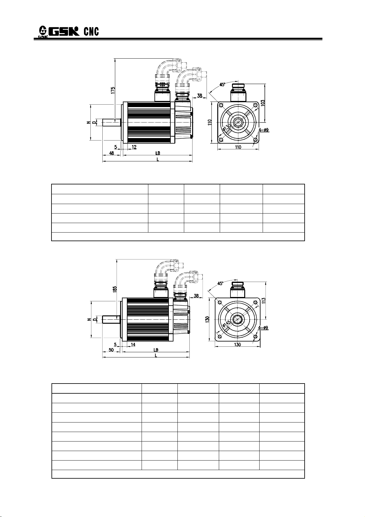
¾ For external dimensions of 110SJT series motor, see figure 2-2, table 2-2.
Fig. 2-2
Table 2-2
Type D(mm) N(mm) LB(mm) L(mm)
110SJT—M040D(A□) φ19
110SJT—M040E(A□) φ19
110SJT—M060D(A□) φ19
110SJT—M060E(A□) φ19
0
-0.013
0
-0.013
0
-0.013
0
-0.013
Note: LB, L values in the brackets are the length of corresponding motor that with safe brake.
φ95
φ95
φ95
φ95
0
-0.035
0
-0.035
0
-0.035
0
-0.035
186 (237) 241 (292)
186 (237) 241 (292)
212 (263) 267 (318)
212 (263) 267 (318)
¾ For external dimensions of 130SJT series motor, see figure 2-3, table 2-3.
Fig. 2-3
Table 2-3
Type D(mm) N(mm) LB(mm) L(mm)
0
130SJT—M040D(A□) φ22
130SJT—M050D(A□) φ22
130SJT—M060D(A□) φ22
130SJT—M075D(A□) φ22
130SJT—M100B(A□) φ22
130SJT—M100D(A□) φ22
130SJT—M150B(A□) φ22
130SJT—M150D(A□) φ22
-0.013
0
-0.013
0
-0.013
0
-0.013
0
-0.013
0
-0.013
0
-0.013
0
-0.013
Note: LB, L values in the brackets are the length of corresponding motor that with safe brake.
φ110
φ110
φ110
φ110
φ110
φ110
φ110
φ110
0
-0.035
0
-0.035
0
-0.035
0
-0.035
0
-0.035
0
-0.035
0
-0.035
0
-0.035
168 (227) 225 (284)
168 (227) 225 (284)
176 (235) 233 (292)
188 (247) 245 (304)
208 (267) 265 (324)
208 (267) 265 (324)
238 (297) 295 (354)
248 (307) 305 (364)
20
Page 29
Chapter 2 Installation
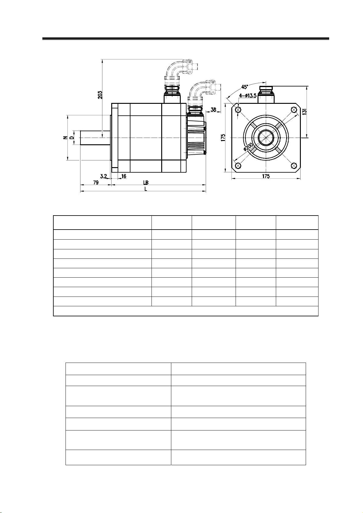
¾ For external dimensions of 175SJT series motor, see figure 2-4, table 2-4.
Fig. 2-4
Table 2-4
Type D(mm) N(mm) LB(mm) L(mm)
175SJT—M150D(A□) φ35
175SJT—M180B(A□) φ35
175SJT—M180D(A□) φ35
175SJT—M220B(A□) φ35
175SJT—M220D(A□) φ35
175SJT—M300B(A□) φ35
175SJT—M300D(A□) φ35
175SJT—M380B(A□) φ35
Note: LB, L values in the brackets are the length of corresponding motor that with safe brake.
+0.01
φ114.3
0
+0.01
φ114.3
0
+0.01
φ114.3
0
+0.01
φ114.3
0
+0.01
φ114.3
0
+0.01
φ114.3
0
+0.01
φ114.3
0
+0.01
φ114.3
0
0
-0.025
0
-0.025
0
-0.025
0
-0.025
0
-0.025
0
-0.025
0
-0.025
0
-0.025
224 (291) 303 (370)
244 (311) 323 (390)
244 (311) 323 (390)
279 (346) 358 (425)
279 (346) 358 (425)
309 (382) 388 (461)
309 (382) 388 (461)
359 (432) 438 (561)
2.1.2 Servo Motor Installation
Servo motor installation, storage and transportation environment
Item Parameter and requirement
Operation temperature
Storage and transportation
temperature
0℃~40℃
-40℃~70℃
Operation humidity
Storage and transportation humidity
Atmosphere environment
There is no corrosive or flammable gas, oil
30%~95%(no dewing)
≤95%(40℃)
mist or dust etc. in the control cabinet
Altitude Altitude of below 1000m
21
Page 30

DAT Series AC Servo Drive Unit User Manual
Attentions
the motor or the motor axis to avoid damage
to internal encoder. Spiral insert and pull
out tools should be used for dismounting.
radial load. Spring coupling is recommended
to connect the load.
to avoid motor loosening.
against water and oil. The cable will bring water and
oil to the motor if it immerses in water and oil.
Therefore, this situation should be prevented from happening.
1. When install the belt pulley, do not strike
2. The servo motor can not bear axial and
3. Stop washer should be used to fix the motor
4. The motor mounting position should be protected
2.2 Servo Unit
The installation environment of the servo motor has direct effect on its functions and service life.
Please install it correctly under the instructions below.
Storage and transportation temperature
Storage and transportation humidity
Operation temperature
Operation humidity
Atmosphere environment
Atmosphere pressure
Item Parameter and requirement
0℃~40℃
-40℃~70℃
30%~95%(no dewing)
≤95%(40℃)
There is no corrosive or flammable gas, oil
mist or dust etc. in the control cabinet
Altitude Altitude of below 1000m
Vibration ≤0.6G(5.9m/s2)
86kPa~106kPa
22
Page 31

2.2.1 Installation Dimension
Chapter 2 Installation
Fig. 2-5 DAT2030,DAT2030C,DAT2050,DAT2050C installation dimension (unit:mm)
Fig. 2-6 DAT2075,DAT2075C,DAT2100,DAT2100C installation dimension (unit:mm)
23
Page 32

DAT Series AC Servo Drive Unit User Manual
2.2.2 Mounting Interval
DAT series servo unit adopts base-plate installation mode, install direction is perpendicular
to the mounting surface. Put the front side of the servo unit forward, and top side upward to
dissipate heat. Please leave space around it.
Fig. 2-7 DAT servo unit mounting interval
Fig. 2-8 shows intervals between servo units, more space should leave in actual installation to
ensure well heat elimination.
24
Fig. 2-8 Mounting intervals between DAT servo units
To prevent environment temperature continuously from being increased, ensure
convection current flows to radiator of the servo unit in the electric cabinet.
Page 33

Please read the following notes carefully and follow it to get safe and smooth operations.
Attentions
Chapter 3 Connection
Chapter 3 CONNECTION
Wiring can only be done by professional technical persons according to
corresponding instructions.
Do wiring and maintenance operation at least 5 minutes after the servo unit is
power off. Ensure the voltage that each main circuit terminal to ground is safe
voltage, or you will be electrocuted.
Please confirm that servo unit and servo motor are earthed correctly.
When you wiring, do not damage the cable by a sharp object, do not pull the
cable lustily, otherwise, it will cause electric shock or poor contact.
Do not cross the main return circuit and signal wire through the same pipe, and
do not tie them together. When wiring, the user separates or crosses the main
return circuit and signal wire, and leaves an interval of 30cm to prevent
interference (from high current wire to signal wire) that makes the servo unit
unable to work properly.
Do not switch on or off the servo unit frequently, because high capacitance in it
will generate high charging current when power on. Power on or off frequently
will decrease the performance of internal components of the servo unit.
Recommended power on or off interval is above 3 minutes.
Power capacity, surge absorber, radio noise filter and other devices should not
be installed at output side of the servo unit or between servo motors.
Keep the main return circuit wire and signal line away from heat abstractor and
motor to avoid insulation property decreasing by heat.
After connection of the main return circuit wire, the terminal protective cap is
covered to avoid electric shock.
25
Page 34

DAT Series AC Servo Drive Unit User Manual
3.1 Connection of Peripherals
Servo unit must be equipped with some peripherals. Proper peripheral ensures the servo
unit works stably. Otherwise, service life will be shortened and even the servo unit will be
damaged.
26
Fig. 3-2 Connection of peripheral DAT2030, DAT2050
Page 35

Chapter 3 Connection
For circuit breaker, isolation transformer, AC wave filter, AC contactor selection, please refer to
appendix B.
Fig. 3-3 Connection of peripheral DAT2030C, DAT2050C
For circuit breaker, isolation transformer, AC wave filter, AC contactor selection, please refer to
appendix B.
27
Page 36

DAT Series AC Servo Drive Unit User Manual
L3L2L1
3-phase AC 380V power
RESET
CNC system
位置
转换
信息
退格
取消删除
上档
输入
程序 系统
图形
Braking resistor (optional)
Not connect to external braking resistor,
B, B1 are connected;
Connect to external braking resistor,
设置
帮助
B, B1 are not connected
AC380V
AC220V
PE
U
V
W
R
S
T
Protective earth wire
Control circuit
Fig. 3-4 Connection of peripheral DAT2075, DAT2100
For circuit breaker, isolation transformer, AC wave filter, AC contactor selection, please refer to
appendix B.
28
Page 37

Chapter 3 Connection
RESET
CNC system
位置
转换
信息
退格
取消删除
上档
输入
程序 系统
图形
3-phase AC 380V power
L3L2L1
Braking resistor (optional)
Not connect to external braking resistor,
B, B1 are connected;
设置
帮助
Connect to external braking resistor,
B, B1 are not connected
AC380V
AC220V
PE
U
V
W
R
S
T
(necessary)
Circuit breaker
(necessary
Transformer
(Optional)
Wave filter
Protective earth wire
See section 3.5 for connection of GSKLink
Control circuit
Fig. 3-5 Connection of peripheral DAT2075C, DAT2100C
For circuit breaker, isolation transformer, AC wave filter, AC contactor selection, please refer to
appendix B.
(necessary)
AC contactor
29
Page 38

DAT Series AC Servo Drive Unit User Manual
3.2 Terminal Connection of Main Circuit
3.2.1 Terminal Connection of Servo Unit
drive unit
DAT series AC servo
Encoder feedback signal
Fig. 3-6 Main circuit connection of DAT series products
The following circuit diagram is recommended for connection of KM1 control circuit in Fig. 3-5:
30
Page 39

Chapter 3 Connection
Section selection of main circuit wiring:
R S T
PE
U V W P B1 B
Current of
the adapted
motor
Input terminal of
AC current
≤6A 1.5 mm2 ≥1.5 mm
6A~10.5A
11A~21A
22A~28A
2.5 mm
4 mm
4 mm
2
≥2.5 mm
2
≥ 4 mm
2
≥ 4 mm
Protective
ground
end
2
2
2
2
Power output end
1.5 mm2 1.5mm2
2.5 mm2 2.5 mm2
4 mm2 4 mm2
4 mm2 4 mm2
For DAT2030 or DAT2030C, DAT2050 or DAT2050C terminal, its
insulation covering is stripped off and the exposed copper wire is
twisted according to the following figure. Press wiring (press terminal
with special tools) with H2.5/18D type tubular terminal (Weidmuller
Company). Insert terminal as the figure, and tighten up terminal screw.
10m m ~ 12m m
For DAT2075 or DAT2075C, DAT2100 or DAT2100C terminal and DAT
series PE terminal connections, insulation covering is stripped off and exposed
copper wire is twisted according to the following figure. Press wiring (press
terminal with special tools) with HRV 2―5S type round pre-insulation terminal.
(Huxi Electric Apparatus co., Ltd), and tighten it up to the ground screw at the
front of the shell.
6m m ~ 8m m
Connection
terminal of
external, internal
brake resistor
31
Page 40

DAT Series AC Servo Drive Unit User Manual
3.2.2 Instructions for Servo Motor Interface
¾ Corresponding relationship between pins of motor power socket and output terminal of the
servo unit
Pin No. of the motor power socket 1 2 3 4
Terminal tab the servo unit PE U V W
¾ Pins connection of safe brake socket
z Pin1, Pin 2 is connected to DC24V, and their positive and negative poles are not distinguished,
pin 3 is earthed.
z For controlling of controlled contact KA, refer to section 6.2 :application of release signal of
band-type brake.
For motor with different power is adapted to the safe brake with different power. When selecting
24V switch power supply, please refer to the following technical parameters of arrester brakes
adapted to different motors.
Seat No. of
the motor
110 4 24V DC 20 0.037
130 8 24V DC 25 0.042
175 32 24V DC 40 0.135
¾ For connection of pins of encoder signal socket, please refer to section 3.4.3.
Rated
torque
Supply
voltage
Coil power of the brake at
20 (unit℃ : W)
Release time
(s)
32
Page 41

Chapter 3 Connection
3.3 Connection of Control Signal
3.3.1 Definition of Pin CN1 of DAT Series Products
¾ The control signal interface CN1 of DAT2000 series products is Pin 44 male, the connector
for making control wire is Pin 44 female (the type is G3150-44FBNS1X1, provided by
WIESON Company). See the following figure for the definition of the pins.
Figure 3-13 Pin CN1 of DAT2000
In the above figure, pins with the same name are connected and shorted in the inner
circuit board.
33
Page 42

DAT Series AC Servo Drive Unit User Manual
¾ Control signal interface CN1 of DAT2000C series products is high-density socket with 50
cores (type: MDR50-10250-55H3JL, provided by 3M company), which pin layout is as
follows:
Fig. 3-14 Pin CN1
Pin
No.
1
2
3
Name Meaning
PBO-
Position
feedback
output
PBO+
signal A
pase
PAO-
Position
Reference
item
6.4
Pin
No.
26
Name Meaning
PZO-
Position
Reference
feedback
output
27
PZO+
signal Z
pase
28 GND digital ground
item
feedback
4
PAO+
output
signal B
6.4
29 NC
pase
5
6
PULS-
PULS+
Position
command pulse
input
3.3.3
30
31
SIGN-
SIGN+
Input direction
of position
command
3.3.3
Speed
7 SC2/INH
selection
2/pulse
5.2.2
6.5.4
32 RIL
CW torque
limit
3.3.4
prohibited
Speed
8 SC1/CLE
selection 1/
pulse clearing
9 NC 34 ZSL
10 RSTP
11 FSTP
CW drive
prohibited
CCW drive
prohibited
5.2.2
6.5.3
33 FIL
CCW torque
limit
Zero-speed
clamped
3.3.4
6.6.3
3.3.4 35 GIN reserve
3.3.4 36 NC
12 ALRS Alarm clearing 3.3.4 37 NC
6.4
13 SON Enabling 3.3.4 38
14 NC 39
Speed arrival
15
COIN+
+/ position
6.6.2
6.5.2
arrival+
34
COM-
COM+
41
COM+
Input power
of control
signal (15~
24VDC)
Page 43

Chapter 3 Connection
Speed arrival
16
17
18 NC 43
19 NC 44 NC
20
21
22
23
24
25
SRDY-
SRDY+
ZSP-
ZSP+
ALM-
ALM+
VCMD+
VCMD-
Servo be
ready to
output
Motor
zero-speed
output
Alarm output 3.3.5
Simulated
command
input
3.3.5
3.3.5
3.3.2
40
42
45 NC
46
47
48 0VA
49 NC
50 NC
COIN-
HOLD-
HOLD+
CZ-
CZ+
+/ position
arrival+
Release
signal of safe
brake output
Zero-point
signal of
encode
output
3.3.2 Input of Speed Command
6.6.2
6.5.2
6.2
3.3.5
VCMD+/ VCMD- are input terminals of speed command input, which receives max. 10V DC
voltage signal, and its terminal input resistance is 20KΩ.
Note: The signal cable uses a shielded line, and the differential signal must use a twisted-pair line.
35
Page 44

DAT Series AC Servo Drive Unit User Manual
3.3.3 Input of Position Command
Position commands PULS+/PULS-,SIGN+/SIGN- can use differential drive method or use
single-end drive method. See example as follows:
z Differential drive method
z Single-end drive method
36
Fig. 3-18 Wiring of NPN type single-end drive
4.7K
4.7K
Fig. 3-19 Wiring of PNP type single-end drive
Page 45

Chapter 3 Connection
~
1. Differential drive method is recommended to use in order to avoid high interference;
In differential drive mode, AM26LS31, MC3487 or similar RS422 drive chip are
recommended.
2. Single-end drive method will decrease action frequency. Under the condition that the
pulse input to circuit, drive current is 10 mA~15mA, external max. power voltage is
limited to 25V, resistance R value is defined. Experiential data: VCC=24V,R=1.3kΩ
2kΩ;VCC=12V,R=510Ω~820Ω;VCC=5V,R=0Ω
There are three kinds of position command input modes, which are set by parameter PA14, can
be received. See the table bellow, and arrow represents the counting edge.
37
Page 46

DAT Series AC Servo Drive Unit User Manual
a. Input interface sequence diagram of pulse + symbol (max. pulse frequency 1MHz)
PULS
SIGN
90%
10%
90%
10%
th
trh trl
ts
tck
tl
ts
CW
trh
CCW
trl
CW
b. Input interface sequence diagram of CCW pulse/CW pulse (max. pulse frequency 1MHz)
c. Input interface sequence diagram of 2-phase command pulse (max. pulse frequency 1MHz)
Parameter
Differential
drive input
(μs)
Single-end
drive input
(μs)
38
Sequence parameters of pulse input are listed bellow.
tck th t
trh trl ts t
l
qcktqh
>1 >0.3 >0.3 <0.2 <0.2 >2 >1 >0.3 >0.3 <0.2 <0.2 >0.2
>5 >2.5 >2.5 <0.3 <0.3 >2.5 >10 >5 >5 <0.3 <0.3 >2.5
tql t
qrh
t
qrl
tqs
Page 47

Chapter 3 Connection
3.3.4 Switching Value Input
Two examples of wiring are provided bellow, Inx represents input point: (SON, ALRS, FSTP,
RSTP, SC1/CLE, SC2/INH, ZSL, FIL, RIL, GIN).
Example of external
switch value
Example of external
photocoupler
DC15V~24V power (above 1A) should be provided for servo unit. It is suggested the same
power with output circuit should be used.
Input coupler is on when Inx connects to 0V, and the signal is ON, input is active. Monitor window
can be used for judgment, when the input point is ON, corresponding LED lights up. When
the input point is OFF, corresponding LED is not work. This monitor window is used for debugging
and examining the control signal of the servo unit.
Detailed instructions for input signals:
¾ COM+, COM- are input ports of external specified power (15V~24V).
39
Page 48

DAT Series AC Servo Drive Unit User Manual
¾ Servo enable is operated when SON is ON. Check the monitor window and
is displayed.
Related
parameters
PA54
Meaning Unit
When there is no external SON signal
input, motor enable is enforced in the
servo unit.
PA54=0:When external input signal
SON is ON, the motor is enabled.
PA54=1:Motor enable is enforced in the
servo unit, and the external SON signal
is not needed.
0
Default
value
Applicable
modes
P,S
The motor is turned on when the servo unit works normally. If the servo unit has troubles,
the alarm code occurs. Please refer to chapter 8 troubles and troubleshooting.
¾ When ALRS is ON, alarms that smaller than No. 9 alarm are cleared by ALRS signal
after trouble clearing. Alarms that bigger than No. 9 alarm can only be cleared after trouble
clearing and power on again. When SON is ON, the function of alarm clearing is invalid.
¾ FSTP, RSTP: Drive prohibition signal is usually matched with stroke switch to avoid
over travel.
Input signal Operation
FSTP RSTP CCW CW
ON ON O O
ON OFF O Prohibited
OFF ON Prohibited O
OFF OFF Prohibited Prohibited
Note: O represents normal. When drive prohibition function is not used, PA20 is set to 1 to shield drive
prohibition function.
40
Page 49

¾ FIL: CCW torque limit. When FIL is ON, the maximum torque of the motor is limited by
the setting of PA36.
¾ RIL: CW torque limit. When RIL is ON, the maximum torque of the motor is limited by the
setting of PA37.
3.3.5 Output of Switch Value
1. In DAT2000 series product, except signal HOLD, CZ, other output signals are
single-end transistor output. Emitter of the coupler has been connected to COM-.
2. Switching value output of DAT2000C series product is double-end transistor output:
Chapter 3 Connection
OUTx represents output points (ALM, SRDY, ZSP, COIN, HOLD, CZ)
z Wiring diagram of single-end transistor output
Example 1: Servo unit matches with system GSK980TDb
External controller
Example 2: Servo unit matches with system 983M
Output of external
relay
41
Page 50

DAT Series AC Servo Drive Unit User Manual
z Wiring diagram of double-end transistor output
External controller
External relay output
When OUTx is connected to COM- or OUTx+ is connected to OUTx, input point is ON.
Monitor window
can be used for judgment, when input point is ON, corresponding
LED lights up. When input point is OFF, corresponding LED does not light.
¾ ALM of the servo unit is output when abnormity is detected. Output state is relevant to PA47.
PA47=0
PA47=1
ALM signal output coupler is OFF when alarm occurs
ALM signal output coupler is ON when alarm occurs
42
Page 51

Chapter 3 Connection
ALM
ALM
Power
(PA47=1)
(PA47=0)
OFF ON
OFF
OFF
No alarm
0.5s
<
No alarm alarm
alarm
¾ SRDY represents servo unit is ready. SRDY signal output photo coupler is connected when
the motor power-on is excited.
¾ ZSP represents zero-speed output, i.e. when the speed of the motor is zero, photo coupler
of ZSP signal output is ON.
¾ CZ represents zero point signal of encode: For incremental encoder, sequence is in
accordance with Z signal (one-rotation signal) feedback from motor encoder, as shown
below:
For absolute type encoder, AB-phase pulse number per circle is set by servo parameter, zero
point signal CZ is output at the same time.
¾ HOLD:Release signal of safe brake of the motor with a band-type brake. Refer to 6.2 for
output logic of this signal.
1. When output signal is open collector type, its maximum load current is 100mA, maximum
voltage of external DC current is 25V. If it exceeds the specific requirement or output end directly
connect to the power, servo unit will be damaged.
2. If the load is inductive load, freewheeling diode should be paralleled with two ends of the
load. If the freewheeling diode is connected reversely, the servo unit will be damaged.
43
Page 52

DAT Series AC Servo Drive Unit User Manual
3.4 Connection of Feedback Signal
3.4.1 Introductions for CN2 of DAT2000
The encoder interface CN2 of the motor of the DAT2000 servo unit is Pin 25 female. The
connector for making control wire is Pin 25 male (the type is G3150-44FBNS1X1, provided by
WIESON Company). See the following figure for the definition of the pins.
Fig. 3-42 CN2 DB 25 female socket
Pin
No.
1 0V 14 FG
2 0V 15 FG
3 0V 16 0V
4 0V
5 5V 18 5V
Name Meaning Pin No. Name Meaning
Frame ground
Encoder power(-)
17 5V
Encoder power(-)
Encoder power(+)
6 5V
7
8
9
10
11
12
W-
V-
U-
Z-
B-
A-
Encoder power(+)
Feedback of
incremental type
encoder W-
Feedback of
incremental type
encoder V-
Feedback of
incremental type
encoder U-
Feedback of
incremental type
encoder Z-
Feedback of
incremental type
encoder B-
Feedback of
incremental type
encoder A-
19
20
21
22
23
24
25 NC
W+
V+
U+
Z+
B+
A+
Feedback of incremental
type encoder W+
Feedback of incremental
type encoder V+
Feedback of incremental
type encoder U+
Feedback of incremental
type encoder Z+
Feedback of incremental
type encoder B+
Feedback of incremental
type encoder A+
13 OH
44
Input terminal of motor
temperature sensor
Page 53

Chapter 3 Connection
This interface is only applicable for feedback signal of incremental encoder. The signal wire uses
differential drive connection. The wiring diagram is shown below:
OH1(CN2-13)is used for connecting overheating detector in the servo motor, which makes the
servo unit have overheating protective function. Internal wiring diagram is shown below:
After connection, set PA 57 of the servo motor according to properties of overheating detector. If
the servo motor has no overheating detector, PA57 is set to 0 and the shielding alarm occurs, OH1,
0V can not be connected.
Related
parameter
Name Unit
Alarm shielding for motor overheating
Parameter
scope
0~2
Default
value
0
Application
mode
P,S
PA57=0:shielding alarm
PA57
PA57=1:logic alarm when the check switch is the normally-closed in the
appropriate motor’s temperature
PA57=2:logic alarm when the check switch is the normally-open in the
appropriate motor’s temperature
3.4.2 Introductions for CN2 OF DAT2000C
Feedback signal interface CN2 of the encoder of the DAT2000C series products are high-density
socket with 26 cores (type: MDR26-10226-55H3JL, provided by 3M company), which pin layout is
shown below:
Fig. 3-45 Pin CN2
45
Page 54

DAT Series AC Servo Drive Unit User Manual
Pin No. Name Meaning Pin No. Name Meaning
1 OH1
2
3
4
5
6
7
8
9
10
11
12
13
1~13 pins combine CN2 interface of DAT2000 series products, which applies to feedback
signal of incremental encoder. Other pins apply to feedback signal of absolute encoder. OH1
(CN2-1)is used for connecting overheating detector in the servo motor, its connection is the
same that of DAT2000 series products.
W+
W-
V+
V-
U+
U-
Z+
Z-
B+
B-
A+
A-
Input terminal of the motor
temperature sensor
Connect incremental
encoder feedback signal
14 NC
15 NC
16 0V
17 0V
18 NC
19 5V
20 5V
21 5V
22 NC
23
24
25
26
MA+
MA-
SL+
SL-
Encoder power(-)
Encoder power(+)
Feedback signal of
absolute encoder
3.4.3 Connection to Encoder Signal of the Motor
The following diagram is a standard wiring of incremental encoder motor matched DAT2000
series products. When users use motors of other company or make encoder cable by
themselves, refer to the standard wiring bellow. (If the motor is with a thermostat, connect the
thermostat to OH1, 0V ports)
46
Page 55

OH1
null
Chapter 3 Connection
motor
Servo motor
Intermediate cable
Drive unit
Fig. 3-46 Encoder wiring of SJT servo motor
The following diagram is a standard wiring of absolute encoder motor matched DAT2000C
series products. When users use motors of other company or make encoder cable by
themselves, refer to the standard wiring bellow. (If the motor with a thermostat, connect the
thermostat to OH1, 0V ports)
Fig. 3-47 Wiring of absolute encoder
Encoder signal socket of SJT series servo motor are all Pin15 male aviation socket, please
select Pin 15 female aviation plug to make signal cable. Exterior of aviation plug of the encoder
signal cable is as follows:
47
Page 56

DAT Series AC Servo Drive Unit User Manual
1. The length of power cable and feedback signal cable of the motor shall be within 20m, the
distance between two cables shall be more than 30cm. Two cables can not be crossed through the
same pipe or tied them together.
2. Signal cable uses stranded shielding cable, cross-section is 0.15mm
shielding layer to PE terminal.
2
~0.20mm2, connect
3.5 GSKLink Communication Function
DAT2000C series servo unit has GSKLink serial communication function. Connect CN4 or CN5
interfaces to GSKLink to realize real-time communication of the CNC. The servo unit can manage
parameters through GSKLink (including parameter storage, parameter alteration, and parameter
backup) or monitor the position, speed, current, humidity and I/O state information.
¾ Connection between CNC and servo unit is as follows:
48
There is a spare commnunication interface on the servo unit that is for GSKLink link.
Serial terminal is to connect a resistor matched with 120Ω/0.25W between CANL of the
interface and CHNH signal terminal.
Page 57

Chapter 3 Connection
¾ Circuit diagram of bus interface CN4, CN5 of GSKLink is as follows:
¾ Communication diagram between GSK988T CNC system and servo unit
¾ Communication connection between servo units
¾ Set related parameters after connecting the communication cable correctly:
Related
parameter
PA58
Name Unit
Servo unit slave No.
Note: Set number to servo unit that connected to GSKLINK communication bus, and
the number cannot be repeated.
Selection of GSKLINK
communication baudrate
Parameter
scope
0~5
0~4
Default
value
PA59=0:Shield GSKLINK communication function;
1
0
Application
mode
P,S
P,S
PA59
PA59=1:Set baudrate to 500k;
PA59=2:Set baudrate to 600k;
PA59=3:Set baudrate to 800k;
PA59=4:Set baudrate to 1M。
49
Page 58

DAT Series AC Servo Drive Unit User Manual
3.6 Examples for Different Working Mode
3.6.1 Speed Mode Wiring of DAT2000 Series Products
Fig. 3-54 DAT2000 speed mode wiring
Signals with mark * in the figure are necessary connection signal.
#1:Minimum power of external given switch power (DC 15V~24V) should not less than 35W.
#2:When speed command is 0V~10V, and PA4=1,PA46=1, SC1, SC2 are taken as CCW, CW
rotation start signal. It is a necessary connection signal at this moment. When PA4=2, it is taken as
an internal speed selection signal.
#3:DG is an output common port. Please connect it to power earth wire of output signal.
#4:OH is not connected to the servo motor without temperature control sensor. Set PA57=0 to
shield motor overheating alarm.
50
Page 59

Chapter 3 Connection
#5:The metal shell of CN1, CN2 interfaces are connected to PE of servo unit, which can be
taken as bonding point of shield line.
3.6.2 Position Mode Connection of DAT2000 Series Products
Single or three phase AC
External given
Alarm clear
CCW drive prohibition
CW drive prohibition
CCW torque limitation
CW torque limitation
Pulse deviation clearing
Pulse command prohibition
Ready
Zero-speed output
Speed arrival
Alarm output
Band-type brake
signal output
Position feedback
output Z pulse
Pulse command input
220V
SON
#
1
DC15V~24V
~
KM1
Power earth wire
*COM+
*COM+ 39
#2
HOLD +
HOLD -
PULS
PULS
SIGN
SIGN
R
S
T
PE
*SON 23
ALRS 8
FSTP
RSTP
FIL
RIL
CLE
INH
11
GIN 1
32
DG
33
DG
SRDY 20
19
ZSP
35
COIN
CZ +
36
CZ -
30
+
-
15
29
+
14
-
r
t
CN 1
38
24
9
25
10
40
41
5ALM
CN
7
6
37
CN
4.1k
1
PE
1
270
270
AC servo drive unit
A
B
Z
U
V
W
PE
CN 2
13 OH1
16
55V
6
17
18
1
20V
3
4
24 A +
12
23
11 B -
22 Z +
10
21
9U-
20 V +
8
19
7W-
14 FG
15 FG
PE
4
#
CN1
27
12
28 PBO +
13
42
43
OH2
5V
5V
5V
0V
0V
0V
A-
B+
Z-
U+
V-
W+
PAO +
PAO -
PBO -
PZO +
PZO -
#
Vcc
GND
A+
A-
B+
B-
Z+
Z-
U+
U-
V+
V-
W+
W-
FG
3
Servo motor
2
3
4
1
2
3
4
7
5
8
6
9
10
13
11
14
12
15
1
M
Motor
Fig. 3-55 Position mode connection of DAT2000
Signals with mark * in the figure are necessary connection signals.
#1:Minimum power of external given switch power (DC 15V~24V) should not less than 35W.
#2:DG is output common port. Please connect it to power earth wire of output signal.
#3:OH is not connected to the servo motor that without temperature control sensor. Set PA57=0
to shield motor overheating alarm.
#4:The metal shells of CN1, CN2 interfaces are connected to PE of servo unit, which can be
taken as bonding point of shield line.
51
Page 60

DAT Series AC Servo Drive Unit User Manual
3.6.3 Speed Mode Connection of DAT2000C Series Products
#3
Zero-speed clamping
CCW torque starting/speed
#2
CW torque starting/speed
External given
SON
Alarm clear
CCW drive prohibition
CW drive prohibition
CCW torque limitation
CW torque limitation
selection 1
selection 2
Single or three phase AC
220V
Power earth wire
#1
DC15V~24V
*COM+
*COM+ 39
*SON 13
ALRS 12
ZSL 34
FSTP 11
RSTP
FIL
RIL
*SC1
*SC2
R
S
T
PE
CN1
41
10
33
32
8
7
P
AC servo drive unit
4.1k
B
B1
U
V
W
PE
4
1OH
16
PE
5
#
0V
CN2
#
Servo motor
2
3
4
1
MS
3~
CN1
38
Alarm output
Servo ready
Speed arrival
Zero-speed output
Band-type brake releasing
signal output
Motor zero point signal
Analog command inPut
-10V~+10V or 0V~+10V
COM-
23
ALM+
22
ALM-
17
SRDY+
16
SRDY-
15
COIN+
40
COIN-
21
ZSP+
20
ZSP-
43
HOLD +
42
HOLD -
47
CZ +
46
CZ -
PE
CN1
DC
* VCMD+ 24
* VCMD-
25
OVA
CN4
CN5
PE
CNC
DAT series
drive unit
Fig.3-56 Speed mode connection of DAT2000C
Signals with mark * in the figure are necessary connection signals.
#1:Minimum power of external given switch power (DC 15V~24V) should not less than 35W.
#2:When speed command is 0V~10V, and PA4=1,PA46=1, SC1, SC2 are taken as CCW, CW
rotation start signal. It is a necessary connection signal at this moment. When PA4=2, it is taken as
an internal speed selection signal.
#3:Short circuit B1 and B terminals when braking resistor is not needed to connect.Connect
resistance to P, B ends when external resistance is needed. Disconnect B1 and B at the same time.
#4:OH is not connected to the servo motor that without temperature control sensor. Set PA57=0
to shield motor overheating alarm.
#5:The metal shell of CN1, CN2 interfaces are connected to PE of servo unit, which can be
taken as bonding point of shield line.
52
Page 61

Chapter 3 Connection
3.6.4 Position Mode Connection of DAT2000C Series Products
#2
External given
Zero-speed clamping
CCW drive prohibition
CW drive prohibition
CCW torque limitation
CW torque limitation
Position deviation clearing
Pulse command prohibition
Alarm output
Servo ready
position arrival
Zero-speed output
Band-type brake
releasing signal output
Motor zero point signal
DC15V~24V
SON
Alarm clear
Single or three phase
AC 220V
Power earth
wire
#1
*
*
*
*
*
SRDY+
SRDY-
COIN+
COM+
COM+ 39
SON 13
ALRS 12
ZSL 34
FSTP 11
RSTP
FIL
RIL
CLE
INH
COM-
ALM+
ALM-
COIN-
ZSP+
ZSP-
HOLD+
HOLD-
CZ+
CZ-
R
S
T
PE
CN1
41
10
33
32
8
7
CN1
38
23
22
17
16
15
40
21
20
43
42
47
46
PE
B1
P
AC servo drive unit
4.1k
Servo motor
B
U
V
W
PE
1OH
16
PE
4
#
PE
0V
CN2
CN4
CN5
2
3
4
1
3
#
CNC
DAT series
drive unit
MS
3~
1
CN
270
6
+
-
5
270
31
+
30
-
Pulse command
input
PULS
PULS
SIGN
SIGN
Fig.3-57 Position mode connection of DAT2000C
Signals with mark * in the figure are necessary connection signals.
#1:Minimum power of external given switch power (DC 15V~24V) should not less than 35W.
#2:Short circuit B1 and B terminals when braking resistor is not needed to connect.
Connect resistance to P, B ends when external resistance is needed. Disconnect B1 and B at the
same time.
#3:OH is not connected to the servo motor that without temperature control sensor. Set PA57=0
to shield motor overheating alarm.
#4:The metal shell of CN1, CN2 interfaces are connected to PE of servo unit, which can be
taken as bonding point of shield line.
53
Page 62

CHAPTER 4 DISPLAY AND OPERATION
4.1 Operation Panel
Detailed functions of keys are as follows:
Key Name Function explanation
Plus
Minus
Return
Multiplication
combination key
Demultiplication
combination key
+
+
DAT Series AC Servo Drive Unit User Manual
1. Parameter No. or parameter value is increased
2. Upturn1-level menu
3. Increase motor speed when manual operation
4. CCW rotation starting when jog operation
1.Parameter No. or parameter value are reduced
2.Page down 2-level menu
3.Decrease motor speed when manual operation
4. CW rotation starting when jog operation
Return to previous level menu or cancel the
operation
Parameter increases 100 by pressing this
combination key once
Parameter decreases 100 by pressing this
combination key once
When modifying the parameter, decimal light in the lower right corner of 6-section LED
lights up, which indicates the value is confirmed to valid, and it can be turned off by
pressing
parameter is invalid .
Confirmation key Enter next lower menu or confirm data alteration
. If exit by pressing when the decimal light is not off, the setting of
4.2 Display Menu
6-section LED is composed of monitor window of DAT series products. Manage the contents
with the form of menu.
First level menu comprises condition monitoring, parameter setting, manual operation, jog
operation. See Fig. 4-1 for the selection and operation of the first level menu.
54
Page 63

Chapter 4 Display and Operation
Fig.4-1 Operation of display menu
4.3 State Monitoring
is state monitoring, and the user can select different monitor state on this menu.
Set value of parameter PA03 here or set initial monitoring state when power on.
Parameter
value
PA3=0
PA3=1
PA3=2
Initial monitor
when power-on
Operation Monitor data Explanation
Current motor speed 1000r/min
【1】
Current motor position lower
five-order (pulse) 【2】
Current motor position higher
five-order(×100000 pulse)
55
Page 64

Parameter
value
Initial monitor when
power-on
DAT Series AC Servo Drive Unit User Manual
Operation Monitor
data
Explanation
PA3=3
PA3=4
PA3=5
PA3=6
PA3=7
PA3=8
PA3=9
PA3=10
PA3=11
Position command lower
five-order (pulse) 【2】
Position command higher
five-order (×100000 pulse)
Position deviation lower
five-order (pulse) 【2】
Position deviation higher
five-order (×100000 pulse)
Reserve
Motor torque 70%
Motor current 2.3A
Position mode is current control
mode
Pulse current of position
command is 283.8KHZ
PA3=12
PA3=13
PA3=14
PA3=15
PA3=16
PA3=17
PA3=18
PA3=19
PA3=20
PA3=21
Reserve
Reserve
Speed command is 210r/min
Torque command 20%
Input terminal state 【4】
Output terminal state 【4】
Reserve
Operating 【5】
Display No.9 alarm
Sample value of analog voltage
of high speed section
56
Page 65

Param
eter
Initial
monitor
Chapter 4 Display and Operation
Operation Monitor data Explanation
PA3=22
PA3=23
PA3=24
PA3=25
PA3=26
PA3=27
PA3=28
PA3=29
PA3=30
Sample value of analog voltage of low
speed section
Software version No.
Hardware version No.
Rated torque of the motor is 15N·m
Rated current of the motor is 14.5A
Rotation inertia of the motor
Input power is 1Kw
Radiator temperature is 32 centigrade
degrees
Voltage of DC bus line is 318V
PA3=31
Single-turn position of the motor 【3】
Lower digit of absolute position of the
PA3=32
motor 【3】
Higher digit of absolute position of the
PA3=33
motor 【3】
【1】In
1000r/min. If it rotates in CW direction, negative rotational speed
r is motor speed code, 1000 indicates that CCW speed of the motor is
,
is displayed. Unit: r/min.
【2】Feedback position value of the motor encoder consists of two parts: POS.(higher-five-order)
+POS(lower-five-order).
Example:
× 100000 + =1845806 pulses
As the same principle, pulse value of the position command is composed of two parts:
CPO.(higher-five-order)+CPO (lower-five-order).
Example:
× 100000 + =1845810 pulses
Relationship between CPO and POS:
Calculation formular of position deviation(EPO)when electronic gear ratio is 1:1:
57
Page 66

DAT Series AC Servo Drive Unit User Manual
- =
- =
【3】When 17-digit absolute encoder is used,
displays the position of motor rotor at
each rev, the display scope is 0~131071. If multi-coil absolute encoder (if 12-17 digit absolute
encoder) is selected, that is, the counting scope of each rev is 17-digit (0~131071),coil counting is
12-digit (0~4095). The motor position includes two parts
+
during rotation,
displayed value scope is 0~536870911.
In single-circle absolute encoder, displays of and +
consistent.
are
【4】Refer to section 3.3.4 for states of input terminal, section 3.3.5 for states of output terminal.
【5】Display of operation state
Operation methods for monitor state selection are introduced bellow.
Example: There are two ways to enter low five-digit
state of current position.
Method 1: Select state monitoring directly.
Method 2: Select state monitoring with parameters.
58
Fig.4-2 Select state monitoring with parameters
Page 67

4.4 Parameter Setting
Chapter 4 Display and Operation
Default value: After set PA1 according to motor type, and execute operation
corresponding value becomes the default value.
Operations for motor default value recovery:
1. Input specific code for altering motor parameters, that is PA0=385.
2. Search for corresponding type code of current motor according to code list in Appendix A.
3. Input motor type code to PA1, press
execute
Related
parameter
to complete the operation of defaulted valued recovery.
Name Unit
Parameter altering code
to enter parameter management menu, and
Parameter
scope
0~9999
Default
value
315
Application
PA0
When PA0=315, parameters except PA1, PA2 can be altered
PA1 Motor type code
0~185
0
Taking example of recovering default parameter of 130SJT-M100D(A□)(motor type is 50)
below:
,
mode
P,S
P,S
Press 2 times
Fig.4-3 Alter default parameter of the motor
1. 385 is specific code for setting default parameter of the motor. PA1 can be altered
when PA0=385.
2. User can evaluate whether the default parameter of the servo unit is suitable for the
motor through the operation of setting motor default parameter and related parameters
that are written into default value or PA1 parameter value (see appendix A). If PA1
parameter value without a corresponding motor type code, the motor may not work
59
Page 68

normally.
DAT Series AC Servo Drive Unit User Manual
3. Press
key to validate the parameter after alteration. Now, the altered value is
reflected on the controller. If you are not satisfy with the parameters that is being altered,
don’t press key, press key to exit, and the parameter value is restored to the
one before alteration. If you hope the altered parameter is valid after power off, please
execute parameter writing operation.
On parameter setting, combination keys +
makes parameter increases hundred-fold or
decreases hundred-fold. Take the operation of changing the value of PA24 from 100 to 1800 as
example.
Fig.4-4 Usage of key combination
4.5 Parameter Management
This part introduced operations for parameter write, reading, backup, recovery and default
value recovery of DAT series servo unit in details. See the following figure for data storage
relationship of parameter management.
System power on:
Parameter
write-in
Parameter
read
Parameter
backup
Backup
recovery
Call out the
default
:
EEPROM parameter area
:
:
:
Memory
EEPROM parameter area
Memory
EEPROM backup area
the default parameters
:
EEPROM parameter area
EEPROM backup area
Memory,
EEPROM parameter area
Fig.4-5 Storage diagram of parameter management
¾ EE-SEt Parameter write indicates that write the parameters in the memory to EEPROM
parameter area. Parameter alteration only changes the parameter value. It will change into
original value after power on again. If the parameter value is needed to be changed forever,
Memory
Memory
Memory
60
Page 69

Chapter 4 Display and Operation
parameter write operation is used. Write parameter in the memory to EEPROM parameter area,
and the altered value will be used after power on again.
¾ EE-rd Parameter reading indicates that read data from EEPROM parameter area into memory.
This process will be done once after power on. At the beginning, parameter values in the
memory are the same as the ones in the EEPROM parameter areas. Parameter value in the
memory will be changed after altering the parameter. If user is not satisfy with the altered
parameter or the parameter is disarrayed, execute parameter reading operation. Read the data
from EEPROM parameter area into memory again, recover original parameter at power on.
¾ EE-bA Parameter backup. Write parameter in the memory to EEPROM backup area. This
function used to prevent incorrect alteration and the original parameter can not be recovered.
¾ EE-rS Backup recovery. Read parameters from EEPROM backup area to the memory. Write
operation is needed, otherwise, the parameter will not change after power on.
¾ EE-dEF Default value recovery. It indicates that default value of corresponding parameter is
read to the memory, and it is written to parameter area of EEPROM. The default parameter of
the motor will be used at power on again. (See section 4.4 for parameter setting)
Operations for parameter management are as follows:
Parameter
write-in
Parameter read
Parameter
backup
Backup
recovery
Default
recovery
Fig. 4-6 Parameter management
Parameter writing example:
Power on
Press 2
times
Press 5
times
Point flash is modified
at the 0 bit position
Modification
The data is modified and the
0 bit is always lighted up.
Successful
operation
Operation
failure
Press 2
times
Point flash is modified
at the 0 bit position
The data modification is
affirmed and the 0 bit
indicator is turned off.
1 s
Fig. 4-7 Steps of parameter writing
61
Page 70

DAT Series AC Servo Drive Unit User Manual
CHAPTER 5 DEBUGGING AND OPERATION
Attention: When using the servo unit first time, users should page out the monitoring
window of motor current after the first power on. Once SON turns into ON, please monitor in time
the amount of motor current. If the current exceeds the rated amount, cut off the power
immediately and check the parameter setting of the wiring and servo unit, or the motor is very
likely to be damaged.
Debugging and operation modes will be introduced in this chapter in accordance with the values
of PA4 parameter.
Relevant
parameter
PA4
Name Unit
Work mode choice
Parameter
range
0~6
Default
Value
1
Application
modes
P,S
z PA4=0:Position mode;
Set the direction and angle of motor rotation through digital pulse, the
motor rotor controlled by servo unit will rotate to the corresponding angle in
accordance with the preset direction. The rotary angle (position) and speed are
both controllable.
z PA4=1: External analog voltage command speed mode
Set the direction and angle of motor rotation through analog voltage, the
motor rotor controlled by servo unit will rotate to the corresponding angle in
accordance with the preset direction and speed. This mode can not only
enhance motor’s fast action capability, but also strengthen its turbulence-resist
ability of operation speed
z PA4=2:Internal digital command speed mode
Users should set the values of PA24~PA27 which will be chosen as the
internal speed command corresponding to the rotary speed of motor through
status combination of input points SC1 and SC2 in CN1,
z PA4=3:Manual mode
Operate under the menu
or
’.
accelerate or decelerate by pressing ‘
,
z PA4=4:Jog mode
Operate under the menu
, set the Jog speed value of PA21 first,
62
then proceed CCW, CW revolving operation by pressing ‘
z PA4=5: Encoder Zero-setting, preset well in production, no need to set
again.
z PA4=6: Analog Zero-setting, preset well in production, no need to set
again.
There are normally the following four steps in the operation of a new servo unit.
or ’.
Page 71

Chapter 5 Debugging run
The first three steps will be illustrated to facilitate users for a faster operation of the servo
drive device. Users with different requirements may refer to “Function Debugging” of Chapter Six
for detailed information.
z When using the servo unit first time, manual operation or JOG operation without
connected load is recommended. Make sure the servo unit and motor function
normally after moving, oscillating or assembling.
z After confirming the drive device work properly without connected load, users
connect CN1 control signal and proceed debugging and operating in speed mode or
position mode according to users’ practical needs.
z After the debugging of signal connection, parameter setting and motor operation run
regularly, connect the load for loaded operation.
5.1 Manual and Jog operation
First of all, wire correctly according to the following figure, do NOT connect motor load.
Fig. 5-1 Major loops connection illustration
The following schematic diagram is recommended to wire the control circuit of KMI.
63
Page 72

DAT Series AC Servo Drive Unit User Manual
After wire correctly, check according to the following illustrations before power on:
Items to be examined Examine methods
The specification of servo unit and motor
matching or not.
Breaker, contactor and isolation transformer
connected correctly or not.
R, S, T, PE, P, B1, B and U, V, W,
PE connected correctly or not。
Motor encoder feedback signal wire
connected correctly or not.
Major loop terminal screw fixed firmly or not. Check if any loose with screwdriver.
Make sure connect normally, and then turn on the power as the following time sequence.
Refer to instruction manual to check
nameplates of servo unit and motor
Refer to “Choose of Peripheral Equipments”
on Appendix B.
Make sure field power circuit, if necessary,
use multimeter for measurement.
Refer to Manual 3.4
5.1.1 Manual Operation
After the servo unit turned on,
is out-of-action, alarming code
Eight (Abnormal and Managing) for solution.
Essential
Parameter
PA4 Work mode choice
PA54 Interior enabling
Name Unit
will show as in normal condition; if the servo unit
will show, in this condition please refer to Chapter
Parameter
range
0~6
0~1
Default
Value
0
0
Application
Mode
P,S
P,S
64
Page 73

Steps of manual operation (PA4=3) as follows:
Chapter 5 Debugging run
1. Just after the servo unit is turned on,
monitoring window of motor operation speed.
will show, it’s the
2. Check if PA1 corresponds to the right motor (refer to Appendix A), if
PA1 is correct, the step is skipped, otherwise the user output the default
Press 2
times
parameters which corresponds to the servo motor of the servo unit (see
section 4.4 for operation methods ).
3. Set PA4=3 and choose the manual operation mode.
4. Set PA54=1, interior enabling (before enabling, make sure no danger
to rotate the motor shaft); (If the user wants to cancel interior enabling,
set PA54=0)
5. Enter manual operation manual per the left operation drawing.
(previous parameter setting omitted)
Acc.
Dec.
6. Keep pressing
, motor begins accelerating, release the button,
speed remains unchanged;
keep pressing
, and motor begins decelerating till zero speed, the
motor will reverse-accelerate.
If there is abnormal condition in manual operation, such as oscillating or noisy in
motor, it’s necessary to debug the speed loop parameters of PA5,PA6 and PA8.
Refer to 6.1 for specific debugging methods.
5.1.2 Jog Operation
After the servo unit is turned on,
unit is out-of-action, alarming code
Chapter Eight (Abnormal and Managing) for solution.
Essential
Parameter
PA4 Work mode choice
PA21 JOG operation speed r/min
PA54 Interior enabling
Name Unit
will show as in normal condition; if the servo
will show, in this condition please refer to
Parameter
range
0~6
-3000~3000
0~1
Default
Application
Value
0
120 S
0
Mode
P,S
P,S
Like manual operation, Jog operation also proceeds through operation panel.
65
Page 74

DAT Series AC Servo Drive Unit User Manual
Steps of Jog operation (PA4=4) as follows:
1. Just after the servo unit turned on,
monitoring window of motor operation speed.
2. Check if PA1 corresponds to the right motor (refer to Appendix A), if
PA1 is correct, the step is skip, otherwise the user outputs the default
parameters which corresponds to the servo motor of the servo unit (see
section 4.4 for operation methods ).
3. Set PA4=4 and choose the Jog operation mode.
Set PA21=500, Jog speed: 500 r/min.
4. Set PA54=1, interior enabling (before enabling, make sure no danger
to rotate the motor shaft); (If the user wants to cancel interior enabling,
set PA54=0)
5. Enter manual operation manual per the left operation drawing.
(previous parameter setting omitted)
6. Keep pressing
preset per PA21;
keep pressing
PA21. Release the button, motor stops rotating and remains
zero-speed.
, motor will operate at the speed of 500 r/min
, motor will reverse-operate per the speed set per
will show, it’s the
If there is abnormal condition in Jog operation, such as oscillating or noisy in motor,
it’s necessary to debug the speed loop parameters of PA5,PA6 and PA8. Refer to
6.1 for specific debugging methods.
.
5.2 Speed mode operation
5.2.1 External analog voltage command
① First, refer to the wiring diagrams in section 3.61 (DAT 2000 series) or section 3.6.3
(DAT2000C series) for correct wiring, and pay attention to the essential input signals in the following
chart which must be connected to.
②,After correct connection, all of the input signals must be OFF, the power is turned on and the
essential parameters are set .
Essential
parameter
Parameter illustration
66
PA4 PA4=1 Choose external analog voltage command speed mode
Voltage range of analog control signal under speed mode:
PA46
PA46= 0:(-10V~+10V)effective, voltage command is positive, motor CCW
rotates; Voltage command is negative, motor CW rotates.
PA46= 1:(0~+10V)Effective, SC1, SC2 are the rotating start signals of CCW,
Page 75

CW respectively.
PA46= 0:(-10V~+10V)effective:
PA19= 0:Motor CCW rotates when voltage command is positive.
PA19= 1:Motor CW rotates when voltage command is positive.
Chapter 5 Debugging run
PA19
PA29
PA46= 1:(0~+10V)effective:
PA19= 0:Motor CCW rotates when SC1 is ON, or motor CW rotates
when SC2 is ON.
PA19= 1:Motor CW rotates when SC1 is ON,or motor CCW rotates
when SC2 is ON.
Analog command gain:
PA29 sets the motor rotating speed
corresponding to 1V analog voltage.
Different motors have different rated
rotating speeds, so the value should be
set according to motor models.
E.g.: The responding rated rotating speed
of GSK110SJT-M060D (A□) is 2500r/min.
Set PA29=250.
10V command corresponds to motor at 2500r/min.
5V command corresponds to motor at 1250r/min,
1V command corresponds to motor at 250r/min.
③. Basic debugging operation
1. After the essential parameters is set completely, the user enters into the step of
parameter-read-in operation. (Refer to Section 4.5 for the operation illustration of
on
parameter management)
2. Set a minor analog command to make the input signal SON turns ON, the motor will rotates
following the command.
¾ PA46=0, analog command -10V~+10V effective; take the following diagram for example:
input analog command n(r/min), the on-off control motor of SON will operate or stop; Command
unchanged, if the motor direction reverse, the value of parameter PA19 will change.
67
Page 76

DAT Series AC Servo Drive Unit User Manual
Fig 5-2 Time sequence of motor operation when PA46=0
¾ PA46=1, analog command 0~10V effective, set SC1, SC2 as the positive-and-negative
rotating signals. If analog voltage turns to be negative, the motor will not function.
r/min
n
Analog
command
The rotation
speed when
PA19=0 (r/min)
The rotation
speed when
PA19=1 (r/min)
SC 1
SC 2
0
OFF
2
ON
OFF
ON
OFF
ON OFF
ON
OFF
OFF
n
0
t1t
0
-n
t
Fig 5-3 Time sequence of motor operation when PA46=1
t1, t2 represents the accelerating and decelerating time of motor respectively, the
larger the motor load inertia is, the longer the accelerating & decelerating time will be.
3. Gently increase the analog command to fasten the operation speed of motor. Meanwhile
monitor the motor’s operation condition and check if oscillation or noise occurs, the speed is stable as
well as motor current exceed the rated value. Observe the value of motor current by
monitoring
In normal condition, the displayed current value won’t exceed the rated one.
.
4. If the motor rotates from zero-speed to the maximum positive rotating speed, or from the
maximum negative rotating speed to the maximum positive speed in normal condition, users can
proceed the debugging of other functions.
Troubleshooting of abnormal often met during the operation when the analog command speed
68
Page 77

mode are introduced in the following chart:
Number
1
2 Oscillation or noise occur in motor
3 Motor can only run in one direction;
Abnormality during the debugging
operation
Motor rotating direction is
inconsistent;
Chapter 5 Debugging run
Troubleshooting
Refer to Chapter 6.3 for the switchover of
motor rotating direction
1. Check if the shielding wire is connected
correctly.
2. Refer to Chapter 6.1 for debugging
illustration of fundamental performance
parameters.
1. Inspect the command source mode, and
test the setting of PA46, PA19;
2. Check if the analog command input wire
connected reversely.
4
Set OV command, motor will still
move slightly;
Refer to Chapter 6.6.1 for offset
adjustment.
5.2.2 Internal digital command
① The essential input signal in the following chart must be connected.
Essential input signal Functions
*COM+
*SON Servo enabling signal can individually control motor enabling.
*SC1 speed choice 1
*SC2 speed choice 2
②,Confirm the connection is correct, all input signals must be OFF, the power supply is turned
on and the essential parameter must be set.
Essential
parameter
PA4=2
Choose the internal digital
command speed mode
The input point common terminal is the control supply input terminal.
Name Unit
Digital command
default value
PA24=500
PA25=2000
PA26=-1000
PA27=-1500
Operation speed
Internal speed 1
Internal speed 2
Internal speed 3
Internal speed 4
Parameter
range
0~6
I/O status of selection speed
SC2 SC1
OFF OFF
OFF ON
Default
value
0
ON OFF
ON ON
Application
mode
P,S
69
Page 78

DAT Series AC Servo Drive Unit User Manual
③ Basic debugging operation
1. After the essential parameters is set completely, the drive unit enters into the step of
parameter-read-in operation. (Refer to Section 4.5 for the operation illustration of
on
parameter management)
2. Set input signal SC1 and SC2 turn OFF, the motor will rotate at the internal speed, i.e.
500.0r/min when SON turns ON. Observe the value of motor current by monitoring
In
.
normal condition, the displayed current value won’t exceed the rated one.
3. Switch over the four different internal speeds by changing the combination status of SC1 and
SC2. Meanwhile monitor the motor’s operation condition and check if oscillation or noise occurs, the
speed is stable as well as motor current exceed the rated value. Following figure shows the
successive switch-over time sequence of the four speeds.
Motor speed
r/min
2000
r/min
500
0r/min
-1000 r /min
r/min
-1500
SC1
PA 24
Internal
speed 1
OFF
PA 25 PA 26 PA 27
Internal
speed 2
ON ON
Internal
speed 3
OFF
Internal
speed 4
SC2
OFF
ON
4. When motor operates normally at the four-phase internal speed, users can proceed the
debugging of other functions.
Troubleshooting of abnormality during the operation under the internal speed command mode
introduced in the following chart:
NO. Abnormality during the debugging operation Troubleshooting
Refer to Chapter 6.3 for the
1 Motor rotating direction is inconsistent;
switchover of motor rotating
direction
Refer to Chapter 6.1 for debugging
2 Oscillation or noise occurs in motor;
illustration of fundamental
performance parameters.
to judge if the
3
The status of speed choice input signal is
inconsistent with motor speed
Check
input signal correct. (refer to
Chapter 3.3.4 for switching value
input points )
70
Page 79

Chapter 5 Debugging run
5.3 Position Mode Operation
① First, refer to the wiring diagrams in section 3.61 (DAT 2000 series) or section 3.6.3
(DAT2000C series) for correct wiring, and pay attention to the essential input signals in the following
chart which
Essential input signals Function
*COM+
*SON
*PULS+
*PULS-
*SIGN+
*SIGN-
② After correct connection, all of the input signals must be OFF, the power supply is turned on
and the essential parameters must be set.
Essential
parameter
PA4 Choose position mode
Position command E-gear function:
PA12 is the pulse command multiplying factor
PA13 is the pulse command frequency-division factor
Set the E-gear ratio of position command to match various pulse commands.
PA12
PA13
The calculating formula of E-gear ratio is as follows:
Input point common terminal is the control supply input
terminal.
Servo enabling signal can individually control motor
enabling in this mode.
position command input
Input model: 1. pulse + direction
2. CCW pulse+ CW pulse
3. orthogonal pulse A/B phase
Parameter illustration
,
(refer to Chapter 6.4.1 for detailed calculation method.)
position command pulse model choice
PA14=0:pulse + direction
PA14
PA15
PA14=1:CCW pulse + CW pulse
PA14=2:Two-phase orthogonal pulse input; (refer to Chapter 3.3.3 for
position command input)
Position command reverse direction
PA15=0:Maintain the original command direction
PA15=1: Take the reverse direction of input pulse command. (see also
Chapter 6, Section 3)
71
Page 80

DAT Series AC Servo Drive Unit User Manual
③ Basic debugging operation
1. After the essential parameters is set completely, the motor enters into the step of
parameter-read-in operation. (Refer to Section 4.5 for the operation illustration of
parameter management)
2. Turn SON to ON and keep zero-speed, set the position pulse command with small frequency
and then the motor will run. Observe the value of motor current by monitoring
condition, the displayed current value won’t exceed the rated one:
3. Gently increase the analog command to fasten the operation speed of motor. Meanwhile
monitor the motor’s operation condition and check if oscillation or noise occurs, the speed is stable as
well as motor current exceed the rated value.
4. When the motor can operate along with command within the rated rotating speed, and that the
number of position command pulse
showed, users can proceed debugging of other functions.
Troubleshooting of abnormality during the operation under the position command mode are
introduced in the following chart:
No.
Abnormality during the debugging
operation
showed equals to the ones that
Troubleshooting
on
In normal
.
12
PA
×
13
PA
1
2
does not function;
3 Motor rotating direction is inconsistent
4 Oscillation or noise occurs in motor
5 Motor does not function
6
7
inconsistent with the pulse number of
The pulse value of
is inconsistent with the pulse number
No data is displayed, motor
does not function after enabling;
Data is displayed, motor
×
is
PA
Data showed on
command source
PA
showed on
12
13
Test command wiring and upper computer
Test enabling signal and the setting of
essential parameter
Refer to Section 6.3 for the switch-over of
motor rotating direction
Refer to Chapter 6.1 for debugging illustration
of fundamental performance parameters.
Test the mode of command source and
correctly set based on PA14.
1. Check the mask processing of control
signal wire
2. Keep away from strong interference source.
When position command available, SON
signal is not always effective, i.e. SON may
turn OFF sometimes even if there is position
command.
72
Page 81

Chapter 6 Function Debugging
Chapter 6 FUNCTION DEBUGGING
6.1 Fundamental performance parameter debugging illustration
Fig 6-1 Fundamental performance parameter adjustment diagram
When debugging motor parameters, users can first output the default parameters according to
the corresponding motor model codes in Appendix A. If abnormal situations, such as oscillation, noise,
creeping or insufficient force, occur during the operation, and the fundamental performance
parameters need to be adjusted. Generally speaking, parameters in above diagram should first be
adjusted in the inner-ring speed loop, and then the out-ring speed loop.
z PA5 (Speed loop proportional gain):
The larger the PA5 speed loop proportional gain value is, the higher the servo rigidity will be;
while if the value is over large, the motor is liable to oscillate (motor generates abnormal sound) when
starting up or stopping running; the smaller the value is, the slower the motor responds. The user can
add or decrease 5o each time on the basis of the default values for adjustment, and observe the
effect. Please note the general value range of PA5 is 150~900.
z PA6 (Speed loop integral time factor)
The larger the value of PA6 speed loop integral time factor is, the faster the system will respond;
While the system will turn unstable if the preset value is over large, and even oscillation occurs; the
smaller the value is, the slower the motor responds. The integral action may weaken and the
steady-state error can not be decreased if the value is too small. The user can add or decrease 5o
each time on the basis of the default values for adjustment, and observe the effect. Please note the
general value range of PA6 is 20~500.
The proportional gain and integral time constant of speed loop should be proportionally adjusted
73
Page 82

DAT Series AC Servo Drive Unit User Manual
according to specific servo models and load condition. In general, the larger the load inertia is, the
bigger the speed loop proportional gain and integral time factor will be. In the case of no oscillation
occurs in the system, speed loop proportional gain is to be set as bigger as possible.
Fig 6-2 below shows the response curve of phase-step command input of a driven motor with
certain inertia load.
Curve 1 shows the speed phase-step input curve when PA5, PA6 are relatively small; with quite
soft motor character, slow dynamic response and comparatively large steady-state error.
Curve 2 shows the speed step-phase input curve when the value of PA5, PA6 are relatively
proper. The rigidity of motor is moderate and dynamic respond fast.
Curve 3 shows the speed phase-step e input curve when PA5, PA6 are relatively large;
instantaneous overshoot is to be the largest and the motor is liable to oscillate.
Fig. 6-2 Response curve of phase-step command input
z PA8(Speed feedback filtering factor)
The larger the speed feedback filtering factor value is, the faster the speed feedback responds.
The motor will generate big electromagnetic noise if the value is overlarge; the speed feedback will
respond slower as the value decreases, and the speed will fluctuates more which may lead to
oscillation if the value is over small. The user can add or decrease 5o each time on the basis of the
default values for adjustment, and observe the effect. Please note the minimum value of PA8 should
not less than 50.
z PA9 (Position loop proportional gain)
The closed position loop will work when the servo unit position loop adopts simple P adjustment,
position mode and the speed mode orientation function. The larger the position loop proportional gain
is, the faster the position command responds and the bigger the rigidity will be. With overlarge gain
value, the motor will generate position overshoot and even oscillation when it starts or stop working;
74
Page 83

Chapter 6 Function Debugging
the smaller the value is, the slower the response will be and tracking error will thereby increase. The
user can add or decrease 5o each time on the basis of the default values for adjustment, and observe
the effect. Please note Please note the general value range of PA9 is 25~60.
z PA10(Position loop feed-forward gain), PA11(Position loop feed-forward filtering factor):
PA10 adjust the speed loop through the speed information of position command, tracking error
will decrease as the value increases, while the motor is liable to generate overshoot and oscillation if
the value is overlarge.
PA11 actually carries on smoothing processing of the position command feedforward control.
The lager the value is, the faster the phase-step speed command will be responded to, thereby better
restraining the position overshoot and oscillation resulted from the sudden change of command
speed. The smaller the value is, the less obvious the effect of feedforward control will be, while the
control will generate bigger oscillation.
Generally speaking, PA10(Position loop feed-forward gain) and PA11(Position loop
feed-forward filtering factor) may not be used.
z PA50 (Analog command filtering factor)
The smaller the analog command filtering factor value is, the higher interference signal-resistant
ability is. The response to speed command will be too slow if the value is too small. The larger the
value is, the lower interference signal-resistant ability will be, while the response will faster. The user
can add or decrease 50 each time on the basis of the default values for adjustment, and observe the
effect. Please note the minimum of PA50 is no less than 50.
6.2 Application of brake releasing signal
In order to lock the vertical or tilting workbench linked with motor shaft and prevent the falling off
of the table if the servo warning or power absent, the servo motor with electricity-breaking brake, i.e.
brake servo, is usually used. To effectively control the motion of brake motor, brake releasing signal
(HOLD) is furnished in this servo unit.
Electricity-breaking brake can only be used to maintain workbench, definitely can not to
decelerate or to stop machine’s running compulsively.
1. Correctly wire according to fig.6-3, and note the prerequisite connection of essential input
signal in the following chart.
Essential input signal Function
*COM+
*SON Servo enabling signal
Input point common terminal, is the control
supply input terminal.
*HOLD+
Brake releasing signal
*HOLD-
Figure 6-3 shows the wiring theory of practical application of brake releasing signal controlling
brake servo. Users offer 24V power and pay attention to the polarity of leading power when
75
Page 84

DAT Series AC Servo Drive Unit User Manual
connecting brake releasing signal (HOLD±). See the detailed wiring in the diagram below.
power
24 V
Brake motor
Relay
HOLD+
HOLD-
Electricity-breaking brake
DAT2050C
CN1
43
42
Fig. 6-3 Typical example of HOLD± brake releasing signal
Motors with different power will be configured with the electricity-breaking brakes with different
power. So users can refer to the following chart listing the technical parameters of brakes configured
to motors of different specifications when choosing 24V power.
Motor base
number
Rated
torque
Rated
voltage
20 Brake power ℃ (Unit W)
Releasing time
(s)
110 4 24V DC 20 0.037
130 8 24V DC 25 0.042
175 32 24V DC 40 0.135
2. After correctly wiring, switch on the power and set the essential parameters. Considering the
time sequence of HOLD signal, please use the following parameters related to braking action to
adjust the time if there is some tiny movement of the machine or workbench because of the gravity.
Related
parameters
Name Unit
Parameter
range
Default
value
Application
mode
The maximum decelerating
PA51
time of motor before the action
ms
0~30000
50
P,S
of electricity-breaking brake
PA52 servo locked delay time ms
0~30000
50
P,S
Motor speed when
PA53
electricity-breaking brake
r/min
5~3000
30
P,S
acting
Situation 1: when motor is in the state of rest, power supply of servo unit is turned off suddenly.
Generally, when HOLD is turned off, the servo unit will turned off at the same time. Users can
adjust PA52 to delay the turned-off of servo unit to avoid tiny movement that machine or workbench
occurs due to the gravity.
76
Page 85

Chapter 6 Function Debugging
When the servo is turned off, the energy will be released through dynamic braking circuit
in a short time. So if the value of PA52 is set big, the practical servo locking delay time will
not exceed the time released by energy.
Situation 2: the motor is in operation, the servo unit is turned off suddenly.
Do not brake suddenly when the servo unit runs at a high speed, otherwise the brake will
be damaged easily. The HOLD brake releasing signal should be shut off at the right time.
PA51, PA53 should be properly adjusted first to decelerate the motor and then brake.
PA53 is recommended to be set at 30r/min. The value of PA51 should be set according to
the practical machinery movement.
If movement of machinery or workbench occurs because of the delaying of periphery switch
power and relay coil when the power is unexpectedly shut off, the solution below is shown.
77
Page 86

DAT Series AC Servo Drive Unit User Manual
KM1 AC contactor is a control switch connected with servo unit power. A normally-open contacts
of KM1 is connected to circuit of brake releasing signal, and when the power supply is turned off
manually or suddenly, KM1 is turn off first and the normally-open contact is shut off thereby, then the
brake of motor loses power and brake immediately to eliminate the delay of other source and to
further guarantee that there is no movement of machinery or workbench.
78
Page 87

Chapter 6 Function Debugging
6.3 The switchover of motor rotating direction
Standard mode
When all of the parameters of servo unit are set to be the default values, the relationship
between speed/position command and motor rotating direction is the standard mode.
Reversal mode
If the servo motor wiring and speed/position command are unchanged, there is a “reversal
mode” on servo unit which can make the servo motor rotate reversely.
1. Position mode
Related
parameter
PA15
Command
Name Unit
Reverse position command
direction
PA15=0:remain the original command direction
PA15=1:reverse input pulse command
Standard setting(PA15=0) Reversal mode(PA15=1)
Parameter
range
0~1
Default
value
0 P
Application
mode
CCW
command
CW
command
2. Speed mode
Related
parameter
1. If analog command is -10V~+10V: (PA46=0)
PA19=0: analog command positive,motor CCW rotates,analog command
negative,motor CW rotates;
PA19
PA19=1: analog command positive,motor CW rotates,analog command
negative,motor CCW rotates;
CW
Name Unit
Reverse analog
command/reverse rotation
start of CCW, CW
Parameter
range
0~1
Default
value
0 S
CCW
Application
mode
2. If analog command is: 0~10V (PA46=1)
PA19=0,Set the CCW rotating start signal,motor CCW rotates, Set the CW
rotating start signal,motor CW rotates
PA19=1,Set the CW rotating start signal,motor CW rotates, Set the CCW
rotating start signal,motor CCW rotates
79
Page 88

DAT Series AC Servo Drive Unit User Manual
(PA46=1)
CCW command
(PA46=1)
CW command
(PA46=1)
Positive voltage
(PA46=0)
Negative
voltage
(PA46=0)
Standard setting(PA19=0) Reversal mode(PA19=1)
6.4 Output of position feedback signal
Position feedback signal is to conduct within the servo unit frequency division with the pulse
data from motor encoder (PG) and output them to upper computer through CN1 according to the
preset shift pulses to achieve the functions as upper computer position closed loop control.
Output mode Output signal names Function
Differential output
*PAO+
*PAO-
*PBO+
Differential output
*PBO-
*PZO+
Differential output
*PZO-
Two forms of output wave form as below:
Position feedback output signal A
phase
Position feedback output signal B
phase
Position feedback output signal Z
phase
80
Page 89

Chapter 6 Function Debugging
The pulse number of position feedback signal is set by the parameters of drive unit. Set the
parameters as the following chart and according to the different types of encoders corresponding to
the servo motors driven by drive unit (refer to this manual Section 1.2.1 to check the encoder types).
Motor
encoder type
Incremental
type
Absolute type
Related
parameter
PA30
PA31
PA22
PA32
PA22
Illustration
Position feedback output pulse gear ratio should be set in
PA31≥PA30, if PA31<PA30, it will output per PA31=PA3.
The setting will not effect unless they are saved and re-power on
after PA30,PA31 well set each time.
E.g.: as the figure shows, when PA30:PA31= 4:5, the
corresponding pulse number is
PA32:Position feedback signal frequency division ratio. Set the
pulse number that drive unit feedback to upper computer each circle
the motor rotates.
Counting issue of AB phase pulse:
AB phase pulse counting takes 2 phase edge signal as the triggering signal, i.e. it counts 1 once 1
edge signal is acquired. E.g., if set PA32=16, the whole wave form of the upper computer reported
back by drive unit each circle the motor rotates will be as follows:
81
Page 90

DAT Series AC Servo Drive Unit User Manual
6.5 Function Debugging of Position Mode
6.5.1 Position Command E-gear Ratio
Based on the relative machinery change gear, E-gear function refers to the function that can set
the amount of motor movement which equals to the input command as any value through the
adjustment of servo parameter in the controlling process, without any considering to the machinery
reduction ratio or the encoder wiring.
Relative
parameter
PA12
PA13
Position pulse command
multiplying factor
Position pulse command
frequency division factor
Name Unit
Set the parameter of PA12 and PA13, it’ll be convenient to match various pulse sources and
achieve the expected control resolution (i.e. mm/pulse)
The practical load speed=command pulse speed ×G× machinery reduction ratio
The practical minimum displace =minimum command pulse route ×G× machinery reduction ratio
Parameter
range
1~32767
1~32767
Default
value
Application
mode
1 P
1 P
If E-gear ratio G is not 1, the result of division may have remainder, and there will be
position deviation, the maximum deviation is the motor’s minimum rotating amount
(the minimum resolution).
Below is the formula of position command E-gear ratio adapting to absolute-type encoder motor
G: E-gear ratio, recommended range:
C:
L:
Motor encoder wiring
Screw rod lead (mm)
ZM: Number of gear teeth of the screw rod end (if reduction gearbox exists)
ZD: Number of gear teeth of motor end
δ: The minimum output command unit of the system (mm/pulse)
I: Command displacement
S: Practical displacement
CR: Upper computer command multiplying factor
CD: Upper computer command frequency division factor
【e.g.】: Machine system: GSK988T, the motor directly connect with X-axis screw rod, the screw
rod lead: 6mm, motor encoder: 17 bit absolute, leave out the system’s command multiplying and
82
Page 91

Chapter 6 Function Debugging
frequency division factors, what is the E-gear ratio of the servo unit.
Solution: As the motor directly connect with X-axis screw rod, then ZM :ZD=1; as a rule, S=1
and the command displacement equals to the practical displacement; also, if system GSK988T
chooses0.1μ as its machine accuracy,in the diameter programming, the minimum output command
0001.0
unit of the X-axis, δ =
Then set PA12=2048, PA13=1875.
2
mm , substitute “δ” into the formula and get:
6.5.2 Position arrival signal (COIN)
COIN is the position arrival signal under the position mode.
If the position tracking error is less than or equals to the preset value of PA16, servo unit output
position arrival signal, COIN signal output optocoupler conducts.
Relative
parameter
Name Unit
Parameter
range
Default
Application
mode
PA16
Relative
parameter
PA17
Position arrival range Pulse
0~30000
20 P
If the position tracking error(DP-EPO of the display menu)is less than or equals
to the preset value of PA16, the servo unit regards the position has arrived, and
the position arrival signal COIN outputs ON, otherwise outputs OFF.
Command speed
1:
Motor speed
:
2
OFFON
range
PA16
ON
Default
Application
mode
400 P
Position deviation
COIN
Name Unit
Position over-proof test
range
Parameter
0~30000
Under the position mode, if the position tracking error exceeds the parameter
of PA17, the servo unit position over-proof alarm issues Err-4.
83
Page 92

DAT Series AC Servo Drive Unit User Manual
6.5.3 Pulse deviation zero clearing(CLE)
CLE is the signal of pulse deviation zero clearing, if it displays ON under position mode, the
pulse remained in the position deviation counter of the servo unit will be cleared.
6.5.4 Pulse command inhibition (INH)
INH is the signal of pulse command inhibition, if it displays ON under position mode, servo unit
inhibits receiving pulse command.
6.6 Function debugging under speed mode
6.6.1 Adjustment of analog command
The following parameters should be adjusted if the speed commands inconsistent with practical
motor rotating speed.
Parameter Name Unit Parameter range Default
PA43
Analog command null
shift compensation
If command voltage is “0V”, the motor
sometimes can still rotates at a tiny speed,
which is caused by the little (Mv unit)
“excursion (=command excursion) from
upper computer or external command voltage.
PA43 may compensate this excursion in such way:
If the motor excurse to CCW, decrease the
value to PA43 till the motor get zero speed.
-30000~30000
-10V
0 S
100
0
r/min
100
PA43
Adjustment area
10V
2500
84
Page 93

Chapter 6 Function Debugging
If the motor excurse to CW, increase the value to PA43 till the motor get zero speed
The adjusting sequence of the analog value is recommended as follows:
1. First fix the value of PA29 which can be seen as the corresponded motor rotating speed when
PA 29 sets 1V.
2. Adjust PA34 and revise the “excursion” to “0V” to stop the motor.
3. Finally set some speed commands, such as 500r/min, 1500r/min and 2500r/min, then judge if
the motor speed slope consistent with the command according to the motor rotating speed displayed
on LED.
6.6.2 Speed arrival signal(COIN)
COIN is the speed arrival signal under the speed mode.
If the absolute value of practical speed equals to or greater than the setting, COIN signal outputs
optocoupler conducts.
Relative
parameter
PA28
e.g.: Set PA28=50, refers to the output speed arrival signal (COIN) when the practical speed
greater than or equals to 50r/min.
As the diagram below: speed greater than 50r/min, output COIN signal.
Speed arrival signal
output threshold value
Name Unit
r/min
Parameter
range
0~3000
Default
50 S
Application
mode
85
Page 94

DAT Series AC Servo Drive Unit User Manual
6.6.3 Zero speed clamping(ZSL)
When the upper computer controls servo unit by analog voltage command, the zero speed
clamping function can be used if the analog voltage command is required not to be “0V”, the motor
should be stopped and the servo being locked.
The “zero speed clamping” function can be achieved in this way:
ZSL zero speed clamping input point control.
Under speed mode, speed command is not 0 and ZSL displays ON to lock the motor.
86
Page 95

CHAPTER 7 PARAMETERS
7.1 Parameter List
P: Position Control Mode S: Speed Control Mode
No. Name Range
PA0 Password
0~9999
Chapter 7 Parameters
Default
Value
315 P, S
Unit
Applicable
Mode
PA1 Motor model code
PA2 Software version (read only) 105 P, S
PA3 Monitoring setting at initialization
PA4 Working mode selection
PA5 Speed loop proportional gain
PA6 Speed loop integral time coefficient
PA7
PA8 Speed feedback filter coefficient
PA9 Position loop proportional gain
PA10 Position loop feedforward gain
PA11
PA12
PA13
PA14 Position command mode selection
PA15
PA16 Position reach range
PA17
PA18
PA19 Analog speed command inverted
PA20
PA21 JOG running speed
Low-pass filter on current
command
Position feedforward filter
coefficient
Position pulse command
multiplying ratio
Position pulse command frequency
division ratio
Position command direction
reversed
Position excess error detection
range
Position excess error detection
validity selection
Drive unit input prohibition validity
selection
0~185
0~33
0~6
5~2000
50~4000
1~4000
10~4000
20~1000
0~100
10~3000
1~32767
1~32767
0~2
0~1
0~30000
0~30000
0~1
0~1
0~1
-3000~3000
0 P, ,S
0 P, S
0 P, S
200 Hz P, S
100 P, S
1000 ms P, S
1000 P, S
40 1/s P
0
2000 Hz P
1 P
1 P
0 P, S
0 P
20 Pulses P
400 P
0 P
0 S
1 P, S
120 r/min S
%
P
PA22 Position feedback output inverted
PA23 Maximum speed limit
PA24 Internal speed 1
PA25 Internal speed 2
PA26 Internal speed 3
0~1
1~4000
-3000~3000
-3000~3000
-3000~3000
0 P, S
2500 r/min P, S
500 r/min S
2000 r/min S
-1000 r/min S
87
Page 96

DAT Series AC Servo Drive Unit User Manual
No. Name Range
PA27 Internal speed 4
PA28
Speed arrival signal output valve
value
PA29 Analog input gain
PA30
PA31
PA32
Position output pulse multiplying
ratio
Position output pulse frequency
division ratio
Position feedback signal frequency
division ratio
-3000~3000
0~3000
0~400
1~32
1~32
16~32767 20000
Default
Value
Unit
-1500 r/min S
50 r/min S
250 P, S
1
1
Pulses
Applicable
Mode
P, S
PA33 Reserved
PA34 Internal CCW torque limit
PA35 Internal CW torque limit
PA36 External CCW torque limit
PA37 External CW torque limit
PA38
Manual operation, JOG running
torque limit
0~300
-300~0
0~300
-300~0
0~300
300 % P, S
-300 % P, S
100 % P, S
-100 % P, S
100 % S
PA39 Reserved
PA40 Reserved
PA41 Reserved
PA42 Reserved S
PA43
Analog command zero drift
compensation
-30000~
30000
0 0.1r/min S
PA44 Reserved
PA45 Reserved S
PA46 Analog command mode selection
0~1
0 S
PA47 Alarm output inverted
0~1
0 P, S
PA48 Reserved
PA49 Reserved
PA50 Analog command filter coefficient
PA51
The maximum deceleration time
before the safety brake enabled
PA52 Servo lock delay time
PA53
Motor speed when safety brake is
enabled
PA54 Inner enable
1~3000
0~30000
0~30000
5~3000
0~1
1000 S
50 ms P, S
50 ms P, S
30 r/min P, S
0 P, S
PA55 Reserved
PA56 Reserved
PA57 Motor overheat alarm shielded
PA58 GSKLINK servo axis number
PA59
88
GSKLINK communication baudrate
selection
0~2
1~5
0~4
0 P, S
1 P, S
1 P, S
Page 97

The default settings of shaded parameter are related to the motor models; therefore, the
default values vary with motors.
7.2 Parameter Description
Chapter 7 Parameters
Para. Name Range
Password
PA0
PA1
PA2 Software version (read only) \ 105 P, S
PA3
When PA=315, parameters other than PA1,PA2 are modifiable; To modify PA1, it is
Motor model code
Set the model code of the drive motor according to Motor Model Code List (see APPENDIX
A for details), then the default values of the motor can be restored.
Do not modify this default value in general condition.
Monitoring setting at initialization
Monitoring
Value
PA3=0
PA3=1
PA3=2
PA3=3
PA3=4
PA3=5
setting at
initialization
Instruction Value
Motor speed PA3=17
Current motor
position
low-order 5 digits
Current motor
position
high-order 5 digits
×100000 (pulse)
Position
command
low-order 5 digits
Position
command
high-order 5 digits
×100000 (pulse)
Position
difference
low-order 5 digits
0~9999
needed to set PA0 to 385.
0~185
0~33
(pulse)
(pulse)
(pulse)
Default
PA3=18
PA3=19
PA3=20
PA3=21
PA3=22
Value
315 P, S
0 P, S
0 P, S
Monitoring
setting at
initialization
Unit
Applicable
Mode
Instruction
Reserved
Servo unit
working status
Alarm display
Reserved
High-speed
segment
voltage
sampling value
Low-speed
segment
voltage
sampling value
89
Page 98

Para
. Value
PA3
PA3=6
PA3=7
Monitoring
setting at
initialization
DAT Series AC Servo Drive Unit User Manual
Monitoring
Instruction Value
Position
difference
high-order 5
PA3=23
digits ×100000
(pulse)
Motor torque PA3=24
setting at
initialization
Instruction
Software
version No.
Hardware
version No.
PA3=8
PA3=9
PA3=10
Motor current PA3=25
Reserved PA3=26
Current control
mode
PA3=27
Position
PA3=11
command pulse
PA3=28
frequency
PA3=12
PA3=13
Speed command PA3=29
Torque
command
PA3=30
Motor
PA3=14
one-rotation
PA3=31
signal position
PA3=15
PA3=16
Input terminal
status
Output terminal
status
PA3=32
PA3=33
The shaded items in this table are just for the motor with absolute encoder.
Rated torque
Rated current
Rotational
inertia
Input power
Radiator
temperature
DC bus voltage
Single-ring
position
Absolute
position low
order digits
Absolute
position high
order digits
90
Page 99

Continued:
Relevant
Parameter
Name Range
Default
Value
Chapter 7 Parameters
Unit
Applicable
Mode
PA4
Working mode selection
0~6
0 P, S
PA4=0: position mode (mode 1);
Digital pulses determine the rotation direction and angle. The servo unit makes the
rotor rotates in the determined direction and at specified angle. In position mode,
the rotation angle (position) and speed are controllable.
PA4=1: External analog voltage specifies speed (mode 2);
The rotation direction and speed are determined by the analog voltage. The servo
unit makes the rotor rotates in the determined direction and speed. This mode not
only improves the motor response capability, but also enhances the capability of
anti-disturbance.
PA4=2: Internal digit specifies speed (mode 3);
The values of PA24~PA27 set by user are used as speed command. The motor
running speed is selected through the combination of input point SC1 and SC2’
status.
PA4=3: Manual mode (mode 4)
It is operated in Sr— menu. Acceleration/deceleration can be performed through
keys
or .
PA4=4: JOG mode (mode 5);
It is operated in Jr—menu. The motor works at the JOG speed set by parameter.
PA5
PA6
PA7
PA8
CCW/ CW rotation can be selected through keys
or .
PA4=5: Encoder zeroing. (It is adjusted already.)
PA4=6: Analog zeroing (it is adjusted already.)
Speed loop proportional gain
5~2000
200 Hz P, S
The bigger the speed loop proportional gain, the greater the servo rigidity is.
However, excessive value may easily lead to vibration (abnormal sound in the
motor) during motor start or stop. The smaller the value is, the slower response is.
Speed loop integral time
coefficient
50~4000
100 P, S
The greater the speed loop integral time constant value is, the quicker the system
responds. However, excessive value may lead to instability of the system, or even
cause vibration. Smaller value results in slower response, so, set the value as great
as possible on condition that no vibration is generated.
Current command low pass
filter
1~4000
1000 ms P, S
It is used to limit the current command belt, and avoid current rush and vibration.
Set the value as great as possible on condition that on vibration is generated.
Speed feedback filter
coefficient
10~4000
1000 P, S
The greater the speed feedback filter coefficient is, the quicker the speed feedback
responds. However, excessive value may lead to electromagnetic noise. Smaller
value results in slower response, larger speed fluctuation, or even vibration.
91
Page 100

DAT Series AC Servo Drive Unit User Manual
Relevant
Parameter
PA9
PA10
PA11
PA12
PA13
PA14
PA15
Name Range
Position loop proportional
gain
20~1000
Default
Value
Unit
40 1/s P
Applicable
Mode
The greater the position loop proportional gain is, the quicker the response is and
the greater the rigidity is. However, excessive value may lead to vibration during the
motor start or stop. Smaller value results in slower response and greater following
error.
Position loop feedforward
gain
0~100
0 % P
Position loop feedforward gain is to adjust the speed loop according to the speed
information of position command. The greater the value is, the quicker the response
is, and the smaller the following error is. However, excessive setting value may lead
to instantaneous overshoot and vibration. When PA10 is set to 0, the position
feedforward function is invalid.
Position loop feedforward
filter coefficient
10~3000
2000 Hz P
Position loop feedforward filter coefficient is used in the smoothing process of
position command feedforward control. The greater the value is, the quicker the
step response is, which will suppress the overshoot and vibration caused by
sudden speed change. It is valid when PA10 is not set to 0.
Position pulse command
multiplying ratio
Position pulse command
frequency division ratio
1~32767
1~32767
1 P
1 P
Refer to section 6.4.1 Electronic Gear Ratio for details.
Position command mode
selection
0~2
0 P, S
Position command pulse input mode:
PA14=0: pulse + direction
PA14=1: CCW /CW pulse input
PA14=2: AB phase orthogonal pulse input;
Refer to section 3.3.3 Position Command Input for details.
Position command direction
reversed
0~1
0 P
PA15=0: remains the original commanded direction;
PA15=0: the input pulse direction is reversed.
92
PA16
Position reach range
0~30000
20 Pulses P
 Loading...