


IMPORTANT INFORMATION KEEP FOR OPERATOR
 IMPORTANT INFORMATION
OPERATOR MANUAL |
OM-TDB/7 |
Part Number 121002 |
DOMESTIC |
MODEL: TDB/7 |
|
Steam Jacketed Kettle |
|
Self-Contained
Electrically heated
Table top mounted
Tilting
THIS MANUAL MUST BE RETAINED FOR FUTURE REFERENCE. READ, UNDERSTAND AND FOLLOW THE INSTRUCTIONS AND WARNINGS CONTAINED IN THIS MANUAL.
FOR YOUR SAFETY
DO NOT STORE OR USE GASOLINE OR OTHER FLAMMABLE VAPORS AND LIQUIDS IN THE VICINITY OF THIS OR ANY OTHER APPLIANCE.
Information contained in this document is known to be current and accurate at the time of printing/creation. Unified Brands recommends referencing our product line websites, unifiedbrands.net, for the most updated product information and specifications.
OM-TDB/7
|
IMPORTANT — READ FIRST — IMPORTANT |
|
CAUTION: |
BE SURE ALL OPERATORS READ, UNDERSTAND AND FOLLOW THE OPERATING |
|
|
INSTRUCTIONS, CAUTIONS, AND SAFETY INSTRUCTIONS CONTAINED IN THIS MANUAL. |
|
WARNING: |
THIS UNIT IS INTENDED FOR USE IN THE COMMERCIAL HEATING, COOKING AND |
|
|
HOLDING OF WATER AND FOOD PRODUCTS, PER THE INSTRUCTIONS CONTAINED IN |
|
|
THIS MANUAL. ANY OTHER USE COULD RESULT IN SERIOUS PERSONAL INJURY OR |
|
|
DAMAGE TO THE EQUIPMENT AND WILL VOID WARRANTY. |
|
WARNING: |
KETTLE MUST BE INSTALLED BY PERSONNEL QUALIFIED TO WORK WITH ELECTRICITY. |
|
|
IMPROPER INSTALLATION CAN RESULT IN INJURY TO PERSONNEL AND/OR DAMAGE TO |
|
|
EQUIPMENT. |
|
DANGER: |
ELECTRICALLY GROUND THE UNIT AT THE TERMINAL PROVIDED. FAILURE TO GROUND |
|
|
UNIT COULD RESULT IN ELECTROCUTION AND DEATH. |
|
WARNING: |
AVOID ALL DIRECT CONTACT WITH HOT EQUIPMENT SURFACES. DIRECT SKIN |
|
|
CONTACT COULD RESULT IN SEVERE BURNS. |
|
WARNING: |
AVOID ALL DIRECT CONTACT WITH HOT FOOD OR WATER IN THE KETTLE. DIRECT |
|
|
CONTACT COULD RESULT IN SEVERE BURNS. |
|
CAUTION: |
DO NOT OVER FILL THE KETTLE WHEN COOKING, HOLDING OR CLEANING. KEEP |
|
|
LIQUIDS A MINIMUM OF 2-3” (5-8 cm) BELOW THE KETTLE BODY RIM TO ALLOW |
|
|
CLEARANCE FOR STIRRING, BOILING AND SAFE PRODUCT TRANSFER. |
|
WARNING: |
TAKE SPECIAL CARE TO AVOID CONTACT WITH HOT KETTLE BODY OR HOT PRODUCT |
|
|
WHEN ADDING INGREDIENTS, STIRRING OR TRANSFERRING PRODUCT TO ANOTHER |
|
|
CONTAINER. |
|
WARNING: |
WHEN TILTING KETTLE FOR PRODUCT TRANSFER: |
|
|
1) WEAR PROTECTIVE OVEN MITT AND PROTECTIVE APRON. |
|
|
2) USE CONTAINER DEEP ENOUGH TO CONTAIN AND MINIMIZE PRODUCT SPLASHING. |
|
|
3) PLACE CONTAINER ON STABLE, FLAT SURFACE, AS CLOSE TO KETTLE AS |
|
|
POSSIBLE. |
|
|
4) STAND TO LEFT OR RIGHT SIDE OF KETTLE (DEPENDING ON TILTING HANDLE |
|
|
PLACEMENT) WHILE POURING . DO NOT STAND DIRECTLY IN POUR PATH OF HOT |
|
|
CONTENTS. |
|
|
5) POUR SLOWLY, MAINTAIN CONTROL OF KETTLE BODY HANDLE AT ALL TIMES, AND |
|
|
RETURN KETTLE BODY TO UPRIGHT POSITION AFTER CONTAINER IS FILLED OR |
|
|
TRANSFER IS COMPLETE. |
|
|
6) DO NOT OVER FILL CONTAINER. AVOID DIRECT SKIN CONTACT WITH HOT |
|
|
CONTAINER AND ITS CONTENTS. |
|
CAUTION: |
KEEP FLOORS IN FRONT OF KETTLE WORK AREA CLEAN AND DRY. IF SPILLS OCCUR, |
|
|
CLEAN IMMEDIATELY, TO AVOID SLIPS OR FALLS. |
|
WARNING: |
FAILURE TO CHECK SAFETY VALVE OPERATION PERIODICALLY COULD RESULT IN |
|
|
PERSONAL INJURY AND/OR DAMAGE TO EQUIPMENT. |
|
WARNING: |
WHEN TESTING, AVOID ANY EXPOSURE TO THE STEAM BLOWING OUT OF THE SAFETY |
|
|
VALVE. DIRECT CONTACT COULD RESULT IN SEVERE BURNS. |
|
WARNING: |
TO AVOID INJURY, READ AND FOLLOW ALL PRECAUTIONS STATED ON THE LABEL OF |
|
|
THE WATER TREATMENT COMPOUND. |
|
WARNING: |
BEFORE REPLACING ANY PARTS, DISCONNECT THE UNIT FROM THE ELECTRIC POWER |
|
|
SUPPLY. |
|
2
|
OM-TDB/7 |
|
|
IMPORTANT — READ FIRST — IMPORTANT |
|
WARNING: |
KEEP WATER AND SOLUTIONS OUT OF CONTROLS AND ELECTRICAL EQUIPMENT. |
|
|
NEVER SPRAY OR HOSE THE SUPPORT HOUSING OR ELECTRICAL CONNECTIONS. |
|
CAUTION: |
MOST CLEANERS ARE HARMFUL TO THE SKIN, EYES, MUCOUS MEMBRANES AND |
|
|
CLOTHING. PRECAUTIONS SHOULD BE TAKEN. WEAR RUBBER GLOVES, GOGGLES OR |
|
|
FACE SHIELD AND PROTECTIVE CLOTHING. CAREFULLY READ THE WARNINGS AND |
|
|
FOLLOW THE DIRECTIONS ON THE LABEL OF THE CLEANER TO BE USED. |
|
CAUTION: |
USE OF ANY REPLACEMENT PARTS OTHER THAN THOSE SUPPLIED BY GROEN OR THEIR |
|
|
AUTHORIZED DISTRIBUTORS CAN CAUSE OPERATOR INJURY AND DAMAGE TO THE |
|
|
EQUIPMENT, AND WILL VOID ALL WARRANTIES. |
|
IMPORTANT: |
SERVICE PERFORMED BY OTHER THAN FACTORY AUTHORIZED PERSONNEL WILL VOID |
|
|
WARRANTIES. |
|
3
OM-TDB/7
Table of Contents
IMPORTANT OPERATOR WARNINGS . . . . . . . . . . . . . . . . . . . . . . . . . . . . . . . . . . . . . . . . . . . . . . . . . . . . . . . . . . . . . . . . 2 EQUIPMENT DESCRIPTION . . . . . . . . . . . . . . . . . . . . . . . . . . . . . . . . . . . . . . . . . . . . . . . . . . . . . . . . . . . . . . . . . . . . . . . . . 5 INSPECTION & UNPACKING . . . . . . . . . . . . . . . . . . . . . . . . . . . . . . . . . . . . . . . . . . . . . . . . . . . . . . . . . . . . . . . . . . . . . . . . . 7 INSTALLATION . . . . . . . . . . . . . . . . . . . . . . . . . . . . . . . . . . . . . . . . . . . . . . . . . . . . . . . . . . . . . . . . . . . . . . . . . . . . . . . . . . . . 8 INITIAL START-UP . . . . . . . . . . . . . . . . . . . . . . . . . . . . . . . . . . . . . . . . . . . . . . . . . . . . . . . . . . . . . . . . . . . . . . . . . . . . . . . . . 9 OPERATION . . . . . . . . . . . . . . . . . . . . . . . . . . . . . . . . . . . . . . . . . . . . . . . . . . . . . . . . . . . . . . . . . . . . . . . . . . . . . . . . . . . . . . 10 SEQUENCE OF OPERATION . . . . . . . . . . . . . . . . . . . . . . . . . . . . . . . . . . . . . . . . . . . . . . . . . . . . . . . . . . . . . . . . . . . . . . . 12 MAINTENANCE . . . . . . . . . . . . . . . . . . . . . . . . . . . . . . . . . . . . . . . . . . . . . . . . . . . . . . . . . . . . . . . . . . . . . . . . . . . . . . . . . . . 13 CLEANING . . . . . . . . . . . . . . . . . . . . . . . . . . . . . . . . . . . . . . . . . . . . . . . . . . . . . . . . . . . . . . . . . . . . . . . . . . . . . . . . . . . . . . . 17 TROUBLESHOOTING . . . . . . . . . . . . . . . . . . . . . . . . . . . . . . . . . . . . . . . . . . . . . . . . . . . . . . . . . . . . . . . . . . . . . . . . . . . . . . 19 PARTS LISTS
Units Manufactured Before Sept. 1, 1988 . . . . . . . . . . . . . . . . . . . . . . . . . . . . . . . . . . . . . . . . . . . . . . . . . . . . . . . . . . . 20 Units Manufactured Between Sept. 1, 1988 and July 1, 1992 . . . . . . . . . . . . . . . . . . . . . . . . . . . . . . . . . . . . . . . . . . . 22 Units Manufactured Between July 1, 1992 and Feb. 6, 1995 . . . . . . . . . . . . . . . . . . . . . . . . . . . . . . . . . . . . . . . . . . . . 24 Units Manufactured After Feb. 6, 1995 . . . . . . . . . . . . . . . . . . . . . . . . . . . . . . . . . . . . . . . . . . . . . . . . . . . . . . . . . . . . . 26
DIAGRAMS & SCHEMATICS
Units Manufactured Before Sept. 1, 1988 . . . . . . . . . . . . . . . . . . . . . . . . . . . . . . . . . . . . . . . . . . . . . . . . . . . . . . . . . . . 30 Units Manufactured After Sept. 1, 1988 and
Before June 1, 1990 . . . . . . . . . . . . . . . . . . . . . . . . . . . . . . . . . . . . . . . . . . . . . . . . . . . . . . . . . . . . . . . . . . . . . . . . 33 Units Manufactured After June 1, 1990 and
Before July 1, 1992 . . . . . . . . . . . . . . . . . . . . . . . . . . . . . . . . . . . . . . . . . . . . . . . . . . . . . . . . . . . . . . . . . . . . . . . . . 36 Units Manufactured After June 1, 1990 and
Before Feb. 6, 1995 . . . . . . . . . . . . . . . . . . . . . . . . . . . . . . . . . . . . . . . . . . . . . . . . . . . . . . . . . . . . . . . . . . . . . . . . . 37 Units Manufactured After July 1, 1992 and
Before Feb. 6, 1995 . . . . . . . . . . . . . . . . . . . . . . . . . . . . . . . . . . . . . . . . . . . . . . . . . . . . . . . . . . . . . . . . . . . . . . . . . 38 Units Manufactured After Feb. 6, 1995 . . . . . . . . . . . . . . . . . . . . . . . . . . . . . . . . . . . . . . . . . . . . . . . . . . . . . . . . . . . . . 39 SERVICE LOG . . . . . . . . . . . . . . . . . . . . . . . . . . . . . . . . . . . . . . . . . . . . . . . . . . . . . . . . . . . . . . . . . . . . . . . . . . . . . . . . . . . . 42 REFERENCES . . . . . . . . . . . . . . . . . . . . . . . . . . . . . . . . . . . . . . . . . . . . . . . . . . . . . . . . . . . . . . . . . . . . . . . . . . . . . . . . . . . . 42 WARRANTY . . . . . . . . . . . . . . . . . . . . . . . . . . . . . . . . . . . . . . . . . . . . . . . . . . . . . . . . . . . . . . . . . . . . . . . . . . . . . . . . . . . . . . 43
4

OM-TDB/7
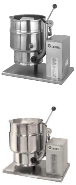
Equipment Description
The Groen TDB/7 is a table top, tilting, steam jacketed kettle with a thermostatically controlled, self-contained, electrically-heated steam supply and appropriate controls, mounted on a sturdy base. The Model TDB/7 is available in 20 or 40 - quart capacity.
The body of the TDB/7 Kettle is constructed of stainless steel, welded into one solid piece. The kettle is furnished with a reinforced rim and a butterfly shaped pouring lip. It has a steam jacket rated for working pressures up to 50 PSI. Kettle finish is 180 emery grit on the inside and bright semideluxe on the outside. A tilt handle allows the operator to manually tilt the kettle body in a controlled manner. Pouring height accepts pans up to 4 inches high on a table top.
A built-in steam generator, sized for the kettle capacity and heated by electricity, delivers steam into the jacket. “Airless” operation of the steam jacket permits uniform, efficient heating at temperatures as low as 150°F and as high as 295°F. In addition to the adjustable thermostat for operating control, the unit has a tilt cut-off switch, low water cut-off, safety valve, and high-limit pressure switch as safety features. A heating indicator light, pressure gauge, and sight glass are provided for monitoring kettle operation.
A single electrical connection is required for installation. The unit may be ordered for use with 208/240 or 480 volt power. All kettles are wired for three-phase operation. For single-phase conversion, see the wiring diagrams in this manual.
KETTLE CHARACTERISTICS
|
|
TDB/7-20+ |
|
TDB/7-40 |
||
Kettle Capacity |
20 qts. |
|
18.8 liters |
40 qts. |
|
37.6 liters |
Jacket Capacity |
4 qts. |
|
3.7 liters |
5 qts. |
|
4.7 liters |
|
|
|
|
|
|
|
Diameter |
14” |
|
36 cm |
16-1/2” |
|
42 cm |
Depth |
11” |
|
28 cm |
14-1/4” |
|
36 cm |
K.W. at 208 V |
|
6.3 |
|
10.8 |
||
|
|
|
|
|
||
K.W. at 240 V |
|
8.4 |
|
14.4 |
||
K.W. at 480 V |
|
6.3 |
|
12.0 |
||
Base Width |
24” |
|
60 cm |
24” |
|
60 cm |
Base Depth |
16” |
|
41 cm |
16” |
|
41 cm |
5
OM-TDB/7
New/Current Models
PreFeb. 1995 Models
Optional equipment available with any model:
1.Stand that supports the unit and holds a pan in position for filling
2.Lift-off cover
3.Basket insert
4.Fill faucet
5.Manual stirrers
6.Motor driven agitator
6
OM-TDB/7
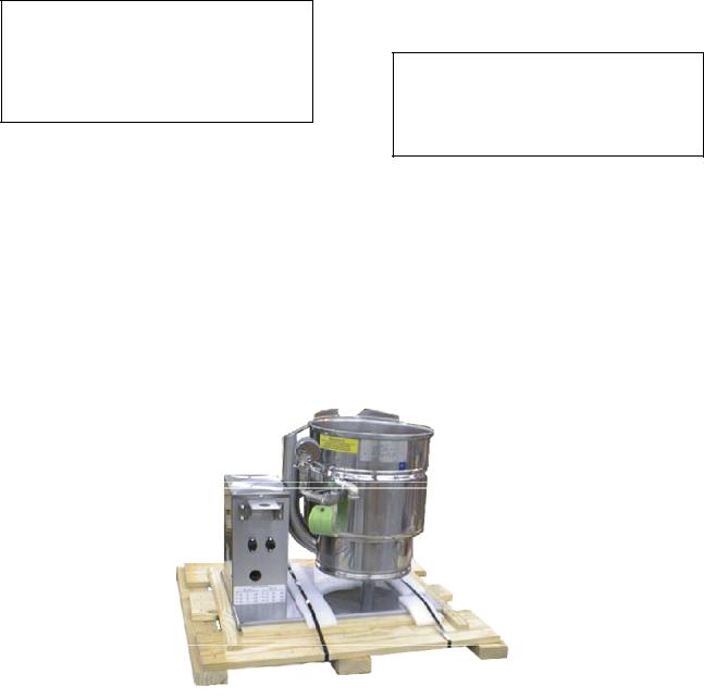
Inspection & Unpacking
The unit will arrive in a heavy shipping carton and will be attached to a skid. Immediately upon receipt, inspect the carton carefully for exterior damage.
CAUTION
SHIPPING STRAPS ARE UNDER TENSION AND CAN SNAP BACK WHEN CUT. TAKE CARE TO AVOID PERSONAL INJURY OR DAMAGE TO THE UNIT BY STAPLES LEFT IN THE WALLS OF THE CARTON.
Carefully cut the polyester straps around the carton and detach the sides of the box from the skid. Pull the carton up off the unit.
Thoroughly inspect the unit for concealed damage. Report any shipping damage or incorrect shipments to the delivery agent.
Write down the model number, serial number, and installation date, and retain this information for future reference. Space for these entries is provided at the top of the Service Log at the back of this manual. Keep this manual on file and available for operators to use.
CAUTION
THIS UNIT WEIGHS 140 TO 163 LB. (64 TO 74 KG). INSTALLER SHOULD OBTAIN HELP AS NEEDED TO LIFT THIS WEIGHT SAFELY.
When installation is to begin, carefully cut the straps which hold the unit on the skid. Lift the unit straight up off the skid. Examine packing materials to be sure loose parts are not discarded with the materials.
Attach the tilt handle (normally shipped inside the kettle) by carefully threading it into the socket on the trunnion support. Be careful to avoid cross-threading fine socket threads.
The TDB/7 is shipped from the factory strapped on a pallet. The tilt handle is inside the kettle.
7

OM-TDB/7
Installation
The Groen Kettle is provided with
complete internal wiring. It is ready for immediate connection. A wiring diagram
is provided in this manual and on the inside of the control housing service
panel. Any mechanical or electrical changes must be approved in by Groen’s Food Service Engineering Department.
WARNING
INSTALLATION OF THE KETTLE MUST BE DONE BY PERSONNEL QUALIFIED TO WORK WITH ELECTRICITY. IMPROPER INSTALLATION CAN RESULT IN INJURY TO PERSONNEL AND/OR DAMAGE TO EQUIPMENT.
The completed unit has been operated at the factory to test all controls and heater elements.
1.Set the kettle in place and level it. The base should be securely fastened to a table or work surface. Four 3/8”-16 N.C. threaded couplings are provided in the base of unit. Installation under a ventilation hood is recommended.
2.Provide electrical power as specified on the electrical information plate attached to the equipment. Observe local codes and/or The National Electrical Code in accordance with ANSI/NFPA 70 - (current edition).
3.The equipment is shipped ready for three phase operation. Refer to the wiring diagram for single phase operation.
4.Bringing the electrical service through the entrance at the rear of the support housing, making a watertight connection with the incoming lines. (A BX connection is not recommended.)
DANGER
ELECTRICALLY GROUND THE UNIT AT THE TERMINAL PROVIDED. FAILURE TO GROUND UNIT COULD RESULT IN ELECTROCUTION AND DEATH.
5.Confirm that the jacket water level is above mid point of sight glass (new models) or between the marks on the gauge glass (old models). If the level is low, follow the instructions under “Jacket Filling and Water Treatment” in the “Maintenance” section of the manual.
6.The open end of the elbow on the outlet of the safety valve must be directed downward on old models. If it is not, turn the elbow to the correct position. On new models the safety valve points down.
7.Any mechanical or electrical change must be approved by the Groen Food Service Engineering Department.
TDB/7 ELECTRICAL SPECIFICATIONS
|
|
20 QUARTS |
40 QUARTS |
||
|
|
|
|
|
|
VOLTAGE |
PHASE |
KW |
AMPS |
KW |
AMPS |
|
|
|
|
|
|
208 |
1 |
6.3 |
31 |
10.8 |
52 |
|
|
|
|
|
|
208 |
3 |
6.3 |
18 |
10.8 |
30 |
|
|
|
|
|
|
240 |
1 |
8.4 |
35 |
14.4 |
60 |
|
|
|
|
|
|
240 |
3 |
8.4 |
20 |
14.4 |
35 |
|
|
|
|
|
|
480 |
1 |
6.3 |
13 |
12.0 |
25 |
|
|
|
|
|
|
480 |
3 |
6.3 |
8 |
12.0 |
15 |
|
|
|
|
|
|
400 |
3 |
7.8 |
11.2 |
13.2 |
19 |
|
|
|
|
|
|
TDB/7 SUPPLY WIRE REQUIREMENTS
Copper only, THHN (90°C)
|
|
20 QUARTS |
40 QUARTS |
||
VOLTAGE |
PHASE |
AWG |
mm |
AWG |
mm |
208 |
1 |
8 |
— |
6 |
— |
|
3 |
12 |
— |
8 |
— |
240 |
1 |
8 |
3.0 |
4 |
3.5 |
|
3 |
10 |
— |
8 |
— |
480 |
1 |
14 |
— |
10 |
|
|
3 |
14 |
— |
12 |
|
400 |
3 |
— |
1.8 |
— |
2.5 |
8
OM-TDB/7
Initial Start-Up
IMPORTANT:
BE SURE ALL OPERATORS READ, UNDERSTAND AND FOLLOW THE OPERATING INSTRUCTIONS, CAUTIONS, AND SAFETY INSTRUCTIONS CONTAINED IN THIS MANUAL.
Now that the kettle has been installed, you should test it to ensure that the unit is operating correctly.
1.Remove all literature and packing materials from inside and outside of the unit.
2.Turn on the electrical service to the unit.
3.Pour 1-2 quarts of water into the kettle.
4.Following “To Start Kettle” instructions in the “Operation” section of this manual, begin heating the water at the highest thermostat setting. The heating indicator light should come on immediately, and heating should continue until the water boils.
5.To shut down the unit, turn the thermostat dial to “OFF”.
WARNING
AVOID ALL DIRECT CONTACT WITH HOT SURFACES. DIRECT SKIN CONTACT COULD RESULT IN SEVERE BURNS.
AVOID ALL DIRECT CONTACT WITH HOT FOOD OR WATER IN THE KETTLE. DIRECT CONTACT COULD RESULT IN SEVERE BURNS.
If the unit functions as described above, it is ready for use. If the unit does not function as intended, contact your local Groen Certified Service Agency.
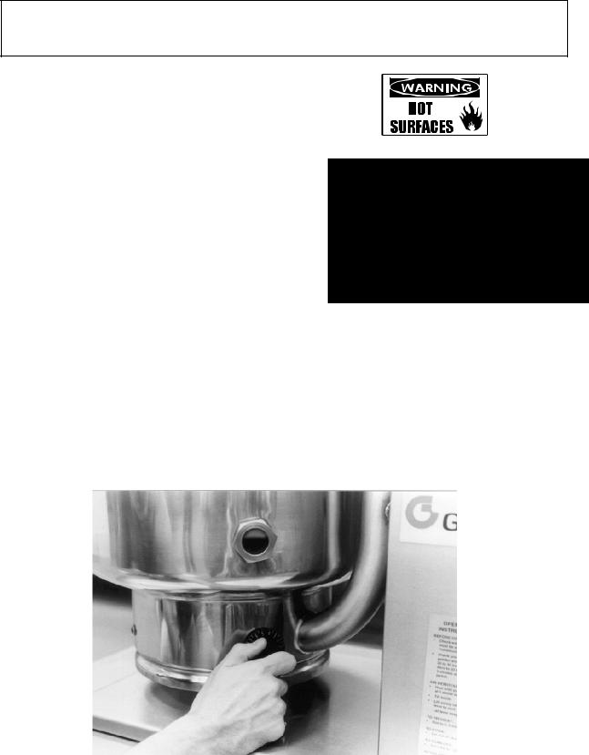
A simple turn of the thermostat controls the Groen TBD/7 Kettle
9

OM-TDB/7
The operator controls kettle heating with the thermostat dial. The dial turns heating element electric power on or off and sets the operating temperature of the kettle.
A.To Start Kettle
1.EVERY DAY make sure that the jacket water level is above the mid-point of the round sight glass (new models) or between the marks on the gauge glass
On most TDB/7 units the jacket water level is shown in a sight glass, right on the kettle.
Operation
(old models). If the level is too low, see “Jacket Filling and Water Treatment” on
page 10 of this manual.
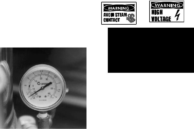
2. Check the pressure gauge. If the gauge does not show 20 to 30 inches of vacuum (that is, a reading of 20 to 30 below 0), see “Jacket Vacuum” on page 10 of this manual.
3.Turn on the electrical power to the unit.
4.Turn the thermostat dial to the desired setting. The heating indicator light indicates that the kettle is heating, and cycling of the
light on and off indicates that the kettle is being held at the set temperature. Once in each cycle the contactors in the support housing will make a clicking sound. This is normal.
B.To Transfer Product or Empty Kettle:
The kettle is designed and manufactured to be
tilted in a controlled manner. Grasp the insulated plastic ball firmly. Maintain a firm grip on handle when tilting, while keeping kettle body in a tilted position and when SLOWLY returning the kettle body to an upright position.
WARNING
AVOID ALL DIRECT CONTACT WITH HOT
SURFACES. DIRECT SKIN CONTACT
COULD RESULT IN SEVERE BURNS.
AVOID ALL DIRECT CONTACT WITH HOT
FOOD OR WATER IN THE KETTLE.
DIRECT CONTACT COULD RESULT IN
SEVERE BURNS.
TAKE SPECIAL CARE TO AVOID CONTACT
WITH HOT KETTLE BODY OR HOT
PRODUCT, WHEN ADDING INGREDIENTS,
STIRRING OR TRANSFERRING PRODUCT
TO ANOTHER CONTAINER.
CAUTION
DO NOT OVERFILL THE KETTLE WHEN
COOKING, HOLDING OR CLEANING.
KEEP LIQUIDS AT LEAST 2-3” (5-8 cm)
BELOW THE KETTLE BODY RIM TO
ALLOW CLEARANCE FOR STIRRING,
B O I L I NG P R O D UC T AND S AF E
TRANSFER.
10
WARNING
WHEN TILTING KETTLE FOR PRODUCT TRANSFER:
1)WEAR PROTECTIVE OVEN MITT AND PROTECTIVE APRON.
2)USE DEEP CONTAINER TO CONTAIN AND MINIMIZE PRODUCT SPLASHING.
3)PLACE CONTAINER ON STABLE, FLAT SURFACE, AS CLOSE TO KETTLE AS POSSIBLE.
4)STAND TO LEFT OR RIGHT OF KETTLE (DEPENDING ON HANDLE PLACEMENT) WHILE POURING — NOT DIRECTLY IN POUR PATH OF HOT CONTENTS.
5)POUR SLOWLY, MAINTAIN CONTROL OF KETTLE BODY HANDLE AT ALL TIMES, AND RETURN KETTLE BODY TO UPRIGHT POSITION AFTER CONTAINER IS FILLED OR TRANSFER IS COMPLETE.
6)DO NOT OVERFILL CONTAINER. AVOID DIRECT SKIN CONTACT WITH HOT CONTAINER AND ITS CONTENTS.
CAUTION
KEEP FLOORS IN FRONT OF THE KETTLE WORK AREA CLEAN AND DRY. IF SPILLS OCCUR, CLEAN AT ONCE TO AVOID SLIPS OR FALLS.
Common Accessories
1.Lift Off Cover
As with stock pot cooking, an optional lift off cover can speed up the heating of water and food products. A cover helps retain heat in the cooking vessel and reduces the amount of heat and humidity released into the kitchen. Use of a cover can reduce some product cook times and help maintain the temperature, color and texture of products being held or simmered for extended periods.
Make sure the plastic ball handle is secure on the lift off cover before using. ALWAYS use the plastic handle to place or remove cover from the kettle. Wear protective oven mitts and a protective apron.
When putting the cover on the kettle, position it on top of kettle rim, with its flat edge facing the pouring lip.
OM-TDB/7
WARNING
AVOID ALL DIRECT CONTACT WITH HOT SURFACES. DIRECT SKIN CONTACT COULD RESULT IN SEVERE BURNS.
AVOID ALL DIRECT CONTACT WITH HOT FOOD OR WATER IN THE KETTLE. DIRECT CONTACT COULD RESULT IN SEVERE BURNS.
When removing cover:
a)Firmly grasp plastic handle
b)Lift rear edge (farthest from operator) 1-2” (3-5 cm) to allow any steam and water vapor to escape the cooking vessel. Wait 2-3 seconds.
c)Tilt cover to 45-60° angle and allow any hot
Lift the rear edge of the cover first.
condensate or product to roll off cover back into kettle.
d)Remove cover, ensuring that any remaining hot condensate or product does not drip on operator, floor or work surfaces.
e)Place cover on safe, flat, sanitary, out-of- the-way surface, or return to kettle rim.
CAUTION
DO NOT TILT KETTLE BODY WITH COVER IN PLACE. COVER MAY SLIDE OFF, CAUSING INJURY TO OPERATOR.
11
OM-TDB/7
2.Basket Insert
An optional kettle basket insert can assist in cooking water-boiled products including eggs, potatoes, vegetables, shell fish, pasta and rice. The nylon mesh liner must be used when cooking product smaller than the mesh size of the basket, which is approximately 1/4” (6 mm). This includes rice and small pasta shapes.
Tips For Use.
a)Allow for the water displacement of the basket and product to be cooked. This may mean only filling the kettle half full of water. Test the basket and product displacement with the kettle OFF, and with cold water in the kettle.
CAUTION
DO NOT OVERFILL THE KETTLE WHEN COOKING, HOLDING OR CLEANING. KEEP LIQUIDS A MINIMUM OF 2-3” (5-8 cm) BELOW THE KETTLE BODY RIM TO ALLOW CLEARANCE FOR STIRRING, BOILING AND SAFE PRODUCT TRANSFER.
WARNING
AVOID ALL DIRECT CONTACT WITH HOT SURFACES. DIRECT SKIN CONTACT COULD RESULT IN SEVERE BURNS.
AVOID ALL DIRECT CONTACT WITH HOT FOOD OR WATER IN THE KETTLE. DIRECT CONTACT COULD RESULT IN SEVERE BURNS.
b)Load basket on a level, stable work surface.
c)Lift the loaded basket with both hands. Get help from another person if the basket is too heavy for safe handling.
d)Slowly lower product into kettle.
e)When removing basket with cooked product, lift basket straight up, ensuring bottom of basket clears the rim and pouring lip of the kettle. Wear protective oven mitts and
protective apron.
d)Allow hot water to fully drain from product, before moving basket away from the kettle. Do not rest kettle basket on kettle rim or pouring lip. If basket is too heavy for individual to lift and safely move, get help from another person. Remove product immediately from basket into another container, being sure to avoid contact with hot product and hot basket or. . .
e)Place basket with food on stable, flat surface, setting it inside a solid steamer or bake pan, to catch any remaining hot water draining from product.
Sequence of Operation
The following “action-reaction” outline is provided to help the user understand how the equipment works.
When the operator starts up the kettle by turning the operating thermostat dial from “OFF” to a desired setting, the thermostat switch closes. This lights up the heating indicator light and causes the contactors to close, allowing power to flow to heating elements. When the temperature of the steam jacket reaches the value corresponding to the dial setting, the thermostat switch opens. This turns off the heating indicator light and causes the contactors to open, stopping the power to the heaters. As soon as the thermostat senses that the kettle is cooling below the set point, the thermostat switch closes, the heating indicator light comes on, the contactors close, and the heaters come
on again. On-off cycling continues, keeping the kettle at the set temperature This is why the heating indicator light cycles on and off during normal operation. Every time the kettle is tilted, the tilt cut-off switch interrupts the power supply to the heaters, so that the heating elements will not operate while not submerged in the jacket water.
If steam pressure greater than 50 PSI is generated in the jacket, the safety valve will open and relieve the excess pressure.
In the event that the jacket water level gets too low and the heating elements overheat, the highlimit control will open and shut off power to the elements until the kettle cools. Setting the operating thermostat dial to “OFF” shuts down all control and heating circuits.
12
OM-TDB/7
Maintenance
NOTICE: Contact Groen or an authorized Groen representative when repairs are required.
1.Periodic Maintenance
A Maintenance & Service Log is provided at the back of this manual with the warranty information. Each time maintenance is performed on your Groen kettle, enter the date on which the work was done, what was done, and who did it. Keep this manual on file and available for operators to use.
Periodic inspection will minimize equipment down time and increase the efficiency of operation. The following points should be checked:
[BY OPERATOR]
a.Check the pressure/vacuum gauge every day. The gauge should show a vacuum of 20 to 30 inches, when the kettle is cold. If it does not, see “Jacket Vacuum” on page 10.
The pressure gauge should show a vacuum of 20 to 30 inches when the kettle is cold.
b.Also check the jacket water level on a daily basis. It should be above mid point of round sight glass (new models) or between the marks on the gauge glass (old models). If the level is low, see “Jacket Filling and Water Treatment” on page 14.
[BY SERVICE TECHNICIAN]
c.Electrical wiring should be kept securely connected and in good condition.
d.The inside of the support housing should be kept clean.
Test the safety valve at least twice each
month. Test the valve with the kettle operating at 15 psi (105 kPa), by holding the test lever for at least 5 seconds. Then release the lever and let the valve snap shut. If the lever does not activate, or there is no evidence of discharge, or the valve leaks, immediately discontinue use of the kettle and contact a qualified Groen service representative.
WARNING
WHEN TESTING, AVOID ANY EXPOSURE TO THE STEAM BLOWING OUT OF THE SAFET Y VALVE. DIRECT CONTACT COULD RESULT IN SEVERE BURNS.
DISCONNECT ELECTRICAL POWER FROM THE KETTLE BEFORE ATTEMPTING TO GREASE THE TRUNNION BEARINGS.
At least twice a year, grease the two trunnion bearings. The bearings are located within the kettle support housing. Remove the access panels from the support housing with a screwdriver to gain access to the grease fittings. Use a lithium-based, multipurpose grease. When the access panels are removed, the mounting bolts for the trunnion bearings and tilt switch can also be checked for tightness. When finished, reassemble access panels to support housing.
2.Jacket Vacuum
When the kettle is cold, a positive pressure reading or a reading around zero on the pressure/vacuum gauge indicates the presence of air in the jacket. Air in the jacket slows down the heating of the kettle.
To remove air:
a.Start the unit. (See the “Operation” section of this manual.) (Be sure there is water or product in the kettle when heating).
b.When the pressure/vacuum gauge reaches a positive pressure reading of 5 PSI, release the trapped air and steam by pulling up or out on the safety valve
13

OM-TDB/7
lever or ring for about 1 second. Repeat this step, then let the pull ring or valve lever snap back into the closed position.
3A. Jacket Filling and Water Treatment (For
units manufactured before July 1, 1992) *
The jacket was charged at the factory with the proper amount of treated water. You may need to restore the water to its proper level, either because water was lost as steam during venting or because treated water was lost by draining.
a.If you are replacing water lost as steam, use distilled water. If you are replacing treated water that ran out of the jacket, prepare more treated water as directed in step 4, “Water Treatment Procedure.”
b.Allow the kettle to cool. Turn the elbow on the safety valve counterclockwise (to avoid thread damage) until the opening of the elbow faces upward.
c.Open the safety valve and pour the water or treated water in at the elbow until the water level rises to a point between the marks on the gauge glass.
CAUTION
BEFORE YOU HEAT THE KETTLE FOR ANY PURPOSE, TURN THE ELBOW CLOCKWISE UNTIL THE OPENING AGAIN FACES DOWNWARD.
e.Air introduced to the jacket during the filling operation must be removed to obtain efficient heating. See “Jacket
Vacuum” above.
* Date of manufacture stamped on National Board data plate.
3B Jacket Filling and Water Treatment (For units manufactured July 1, 1992 to Feb.
6, 1995) *
The jacket was charged at the factory with the proper amount of treated water. You may need to restore the water to its proper level, either because water was lost as steam during venting or because treated water was lost by draining.
IMPORTANT: The pressure gauge must read 0 PSI or less before you fill jacket with water.
To fill jacket with water:
a.If you are replacing water lost as steam, use distilled water. If you are replacing treated water that ran out of the jacket, prepare more treated water as directed in step 4, “Water Treatment Procedure.”
b.Tilt kettle 90° to a full pour position.
c.Remove fill plug with open-end wrench or crescent wrench.
d.Open shutoff valve (turn handle 90° on ball valve).
e.Use a funnel and add water to jacket.
f.Check water level in jacket by tilting kettle to operating position and viewing water gauge glass.
g.Repeat steps e and f until water level is between the maximum and minimum indication marks on the water gauge glass.
h.Close shutoff valve, install fill plug, and return kettle to operating position.
Follow procedure under “Jacket Vacuum” to remove air from kettle jacket.
* Date of manufacture stamped on National Board data plate.
CJacket Filling and Water Treatment (For
units manufactured after Feb. 6 1995) *
The jacket was charged at the factory with the proper amount of treated water. You may need to restore the water to its proper level, either because water was lost as steam during venting or because treated water was lost by draining.
IMPORTANT
Pressure gauge must read 0 PSI or less before you fill jacket with water.
To fill jacket with water:
a.If you are replacing water lost as steam, use distilled water. If you are replacing treated water that ran out of the jacket, prepare more treated water as directed in step 4, “Water Treatment Procedure”.
b.Remove fill plug with open-end wrench or crescent wrench.
c.Open shutoff valve (turn handle 90° on ball valve).
d.Use a funnel and add water to jacket.
e.Check water level in jacket, by viewing water level indicator glass.
f.Continue to add water until the water level indicator glass is 3/4 full.
g.Close shutoff valve, and install fill plug.
Follow procedure in “Jacket Vacuum” to remove air from kettle jacket.
*Date of manufacture stamped on National Board data plate.
14
 Loading...