


OPERATOR/SERVICE MANUAL
IMPORTANT INFORMATION, KEEP FOR OPERATOR
This manual provides information for:
MODELS
BPM-30/40E(CE) International
ECLIPSE™ ERGONOMIC
TILTING BRAISING PAN
· Stainless Steel
· Manual Tilt
· Electric Heated
THIS MANUAL MUST BE RETAINED FOR FUTURE REFERENCE.
READ, UNDERSTAND AND FOLLOW THE INSTRUCTIONS AND
WARNINGS CONTAINED IN THIS MANUAL.
FOR YOUR SAFETY
Do not store or use gasoline or other flammable vapors and liquids in the vicinity of this or any other appliance.
WARNING
Improper installation, adjustment, alteration, service or maintenance can cause property damage, injury or death. Read the installation, operating and maintenance instructions thoroughly before installing or servicing this equipment.
NOTIFY CARRIER OF DAMAGE AT ONCE
It is the responsibility of the consignee to inspect the container upon receipt of same and to determine the possibility of any damage, including concealed damage. Unified Brands suggests that if you are suspicious of damage to make a notation on the delivery receipt. It will be the responsibility of the consignee to file a claim with the carrier. We recommend that you do so at once.
Manufacture Service/Questions 888-994-7636.
Information contained in this document is known to be current and accurate at the time
of printing/creation. Unified Brands recommends referencing our product line websites, unifiedbrands.net, for the most updated product information and specifications.
1055 Mendell Davis Drive
Jackson, MS 39272 888-994-7636, fax 888-864-7636 groen.com
PART NUMBER 153352, REV. A (3/07)

IMPORTANT — READ FIRST — IMPORTANT
THESE APPLIANCES MUST BE INSTALLED BY A COMPETENT PERSON IN CONFORMITY WITH THE INSTALLATION AND SERVICING INSTRUCTIONS AND NATIONAL REGULATIONS IN FORCE AT THE TIME. PARTICULAR ATTENTION MUST BE PAID TO THE FOLLOWING:
I. E. E. REGULATIONS FOR ELECTRICAL INSTALLATIONS
ELECTRICITY AT WORK REGULATIONS
HEALTH AND SAFETY AT WORK ACT
FIRE PRECAUTIONS ACT
LOCAL AND NATIONAL BUILDING REGULATIONS
USERS SHOULD BE CONVERSANT WITH APPROPRIATE PROVISIONS OF THE FIRE PRECAUTIONS ACT. IN PARTICULAR THEY SHOULD BE AWARE OF THE NEED FOR REGULAR SERVICING BY A COMPETENT PERSON TO ENSURE CONTINUED SAFE AND EFFICIENT APPLIANCE PERFORMANCE.
WARNING: TO PREVENT SHOCKS, ALL APPLIANCES WHETHER GAS OR ELECTRIC, MUST BE EARTHED. FAILURE TO EARTH BRAISING PAN COULD RESULT IN ELECTROCUTION AND DEATH.
ON COMPLETION OF THE INSTALLATION, THESE INSTRUCTIONS SHOULD BE LEFT WITH THE ENGINEER-IN-CHARGE FOR REFERENCE DURING SERVICING. FURTHER TO THIS, THE USERS INSTRUCTIONS SHOULD BE HANDED TO THE USERS AND THE INSTALLER SHOULD INSTRUCT THE RESPONSIBLE PERSON(S) IN THE CORRECT OPERATION AND MAINTENANCE OF THE APPLIANCE.
THIS EQUIPMENT IS ONLY FOR PROFESSIONAL USE AND SHALL BE OPERATED BY QUALIFIED PERSONS. IT IS THE RESPONSIBILITY OF THE SUPERVISOR OR EQUIVALENT TO ENSURE THAT USERS WEAR PROTECTIVE CLOTHING, AND TO DRAW ATTENTION TO THE FACT THAT SOME PARTS WILL, BY NECESSITY, BECOME VERY HOT AND WILL CAUSE BURNS IF TOUCHED ACCIDENTALLY.
UNLESS OTHERWISE STATED, PARTS WHICH HAVE BEEN PROTECTED BY THE MANUFACTURER ARE NOT TO BE ADJUSTED BY THE INSTALLER.
WARNING |
:BEFORE ATTEMPTING ANY SERVICING, ENSURE THAT THE ELECTRICAL SUPPLY IS |
|
DISCONNECTED. |
CAUTION: |
SHIPPING STRAPS ARE UNDER TENSION AND CAN SNAP BACK WHEN CUT. |
WARNING: |
TO AVOID DAMAGE OR INJURY, FOLLOW THE WIRING DIAGRAM EXACTLY WHEN |
|
CONNECTING A BRAISING PAN. |
WARNING: |
BEFORE CLEANING THE OUTSIDE OF THE BRAISING PAN, DISCONNECT ELECTRIC POWER. |
|
KEEP WATER AND SOLUTIONS OUT OF CONTROLS AND ELECTRICAL COMPONENTS. |
|
NEVER USE A HIGH PRESSURE HOSE TO CLEAN THE BRAISING PAN. |
NOTICE: |
DO NOT USE ANY DE-GREASER THAT CONTAINS POTASSIUM HYDROXIDE OR SODIUM |
|
HYDROXIDE OR THAT IS ALKALINE. |
WARNING: |
USE OF ANY REPLACEMENT PARTS OTHER THAN THOSE SUPPLIED BY GROEN OR |
|
THEIR AUTHORIZED DISTRIBUTOR VOIDS ALL WARRANTIES AND CAN RESULT IN |
|
BODILY INJURY TO THE OPERATOR AND DAMAGE THE EQUIPMENT. SERVICE BY OTHER |
|
THAN FACTORY-AUTHORIZED PERSONNEL WILL VOID ALL WARRANTIES. |
WARNING: |
HIGH VOLTAGE EXISTS INSIDE CONTROL COMPARTMENTS. DISCONNECT FROM BRANCH |
|
BEFORE SERVICING. FAILURE TO DO SO CAN RESULT IN SERIOUS INJURY OR DEATH. |
CAUTION: |
BE SURE ALL OPERATORS READ, UNDERSTAND AND FOLLOW THE OPERATING |
|
INSTRUCTIONS, CAUTIONS AND SAFETY INSTRUCTIONS CONTAINED N THIS MANUAL. |
WARNING: |
THIS BRAISING PAN IS INTENDED FOR USE IN THE COMMERCIAL HEATING, COOKING AND |
|
HOLDING OF WATER AND FOOD PRODUCTS, PER THE INSTRUCTIONS CONTAINED IN |
|
THIS MANUAL. ANY OTHER USE COULD RESULT IN SERIOUS PERSONAL INJURY OR |
|
DAMAGE TO THE EQUIPMENT AND WILL VOID WARRANTY. |
2 OM/SM-BPM-E CE
|
|
IMPORTANT — READ FIRST — IMPORTANT |
|
|
|
|
|
WARNING: |
AVOID ALL DIRECT CONTACT WITH HOT EQUIPMENT SURFACES. DIRECT SKIN CONTACT |
||
|
COULD RESULT IN SEVERE BURNS. |
||
WARNING: |
AVOID ALL DIRECT CONTACT WITH HOT FOOD OR WATER IN THE BRAISING PAN. |
||
|
DIRECT CONTACT COULD RESULT IN SEVERE BURNS. |
||
CAUTION: |
DO NOT OVER FILL THE BRAISING PAN WHEN COOKING, HOLDING OR CLEANING. KEEP |
||
|
LIQUIDS BELOW THE PAN BODY RIM TO ALLOW CLEARANCE FOR STIRRING, BOILING |
||
|
AND SAFE PRODUCT TRANSFER. |
||
WARNING: |
TAKE SPECIAL CARE TO AVOID CONTACT WITH HOT BRAISING PAN OR HOT PRODUCT |
||
|
WHEN ADDING INGREDIENTS, STIRRING OR TRANSFERRING PRODUCT TO ANOTHER |
||
|
CONTAINER. |
||
WARNING: |
WHEN TILTING BRAISING PAN FOR PRODUCT TRANSFER: |
||
|
1) |
WEAR PROTECTIVE OVEN MITT AND PROTECTIVE APRON. |
|
|
2) |
USE CONTAINER DEEP ENOUGH TO CONTAIN AND MINIMIZE PRODUCT SPLASHING. |
|
|
3) |
PLACE CONTAINER ON STABLE, FLAT SURFACE AS CLOSE TO BRAISING PAN |
|
|
|
AS POSSIBLE. |
|
|
4) |
STAND TO RIGHT SIDE OF BRAISING PAN WHILE POURING. DO NOT STAND |
|
|
|
DIRECTLY IN POUR PATH OF HOT CONTENTS. |
|
|
5) |
POUR SLOWLY, MAINTAIN CONTROL OF BRAISING PAN, AND RETURN BRAISING |
|
|
|
PAN BODY TO UPRIGHT POSITION AFTER CONTAINER IS FILLED OR TRANSFER |
|
|
|
IS COMPLETE. |
|
|
6) |
DO NOT OVER-FILL CONTAINER, AVOID DIRECT SKIN CONTACT WITH HOT |
|
|
|
CONTAINER AND ITS CONTENTS. |
|
CAUTION: |
KEEP FLOORS IN FRONT OF BRAISING PAN WORK AREA CLEAN AND DRY. IF SPILLS |
||
|
OCCUR, CLEAN IMMEDIATELY TO AVOID SLIPS OR FALLS. |
||
WARNING: |
DO NOT HEAT AN EMPTY PAN FOR MORE THAN FIVE MINUTES AT A SETTING HIGHER |
||
|
THAN 300ºF. |
||
WARNING: |
IF THE PAN CONTAINS ITEMS IN SAUCE OR MELTED FAT, THEY COULD SLIDE FORWARD |
||
|
SUDDENLY DURING TILTING AND CAUSE HOT LIQUID TO SPLASH OUT. |
||
WARNING: |
BEFORE ANY CLEANING OPERATION, TURN THE THERMOSTAT TO “OFF” TO CUT OFF |
||
|
POWER TO THE HEATING ELEMENTS. BEFORE CLEANING ANY PART OTHER THAN THE |
||
|
INSIDE OF THE PAN, DISCONNECT THE ELECTRICAL SUPPLY AT THE CIRCUIT BREAKER |
||
|
OR FUSE BOX. |
||
WARNING: |
BE CAREFUL TO AVOID CONTACT WITH CLEANING PRODUCTS IN ACCORDANCE WITH |
||
|
SUPPLIER AND MANUFACTURER RECOMMENDATIONS. MANY CLEANERS ARE HARMFUL |
||
|
TO THE SKIN, EYES, MUCOUS MEMBRANES AND CLOTHING. READ THE WARNINGS AND |
||
|
FOLLOW DIRECTIONS ON THE CLEANER LABEL. |
||
CAUTION: |
NEVER LEAVE A CHLORINE SANITIZER IN CONTACT WITH STAINLESS STEEL FOR LONGER |
||
|
THAN 30 MINUTES. LONGER CONTACT CAN CAUSE CORROSION. |
||
WARNING: |
DO NOT USE ANY FUSE WITH A HIGHER AMP RATING THAN THE RATING SPECIFIED FOR |
||
|
THE CIRCUIT. |
||
OM/SM-BPM-E CE |
3 |
|
Table of Contents |
|
IMPORTANT OPERATOR WARNINGS (READ FIRST)............................................................................ |
2-3 |
|
REFERENCES.............................................................................................................................................. |
4 |
|
EQUIPMENT DESCRIPTION.................................................................................................................... |
5-6 |
|
1. |
INSTALLATION.................................................................................................................................... |
7-8 |
2. |
ASSEMBLY & COMMISSIONING........................................................................................................... |
9 |
3. |
SERVICE.......................................................................................................................................... |
10-13 |
|
WIRING DIAGRAMS........................................................................................................................ |
14-15 |
4. |
USER INSTRUCTIONS.................................................................................................................... |
16-17 |
5. |
CLEANING........................................................................................................................................ |
18-19 |
6. |
MAINTENANCE..................................................................................................................................... |
20 |
7. |
TROUBLESHOOTING........................................................................................................................... |
21 |
PARTS LIST........................................................................................................................................... |
22-28 |
|
SERVICE LOG...................................................................................................................................... |
29-30 |
|
WARRANTY........................................................................................................................................... |
31 |
|
|
References |
American National Standards Institute |
National Fire Protection Association |
1403 Broadway |
60 Battery March Park |
New York, New York 10018 |
Quincy, Massachusetts 02269 |
National Sanitation Foundation |
NFPA/70 THE NATIONAL ELECTRICAL CODE |
|
|
3475 Plymouth Road |
|
Ann Arbor, Michigan 48106 |
|
Underwriters Laboratories, Inc. |
|
333 Pfingsten Road |
|
Northbrook, Illinois 60062 |
|
4 OM/SM-BPM-E CE
Equipment Description
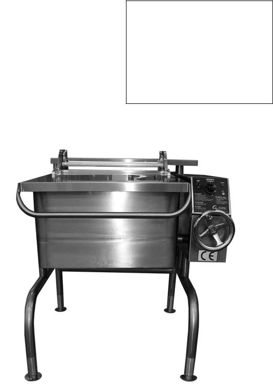
The Groen BPM-E is a stainless steel, electrically heated Braising Pan which is equipped with integrated heating elements, a hand operated or motor powered tilting mechanism, electrical controls and a hinged cover. The Braising Pan serves as a braising unit, griddle, fry pan, oven, kettle, bain-marie, or food warmer and server. It can also be adapted for use as a non-pressure steamer.
The pan body is constructed of heavy-duty stainless steel, welded into a solid piece. It has a polished interior and exterior finish. A pouring lip is welded to the top of the front wall. The cooking surface is a stainless steel clad plate fitted with clamped-on electrical heating elements. The elements are positioned to ensure uniform heat transfer over the entire surface.
Model BPM is mounted on an open-legframe whichisfabricatedfromtubularstainless steel.
Aneasilyoperatedworm andgearmechanism tilts the pan body and provides precise control for pouring or dumping its contents.
The following sizes and options are available:
This tilting mechanism is located in a stainless steel console to right of the pan body. To facilitate cleaning, the pan body can be tilted past the vertical position.
Heatingelementsandotherelectricalcomponents are enclosed for safety. The thermostat, heating indicator light and tilting switch are contained in a compact control console which is mounted to the right of the pan body.
The thermostat provides automatic control of cooking temperature. Turning the thermostat dial starts and stops heating and sets the pan temperature. Only one electrical connection is required to install the unit.
A vented, heavy gauge, one-piece, stainless steel cover with a rear condensate drip shield on the underside is standard on the Braising Pan. A fully enclosed torsion bar-type counter-balance provides easy operation to open the cover to maintain it open at any position. The cover opens to the back. It is hinged to the frame, so it moves independently from the pan body.
MODELS |
Pan Dimensions (Inside) |
|
||
|
|
|
|
|
Left to Right |
Front to Back |
|
Depth |
|
|
|
|||
|
|
|
|
|
BPM-30E |
26.25 |
28.25 |
|
10" |
|
|
|
|
|
BPM-40E |
35.75 |
28.25 |
|
10" |
|
|
|
|
|
The following optional equipment may be added to any floor model listed above:
1.Fill faucet - swing spout single or double pantry
2.Fill faucet - 48" or 60" spray hose assembly - single or double pantry
3.Caster mounting kit
4.Flanged Feet Kit
5.Draw-O Valve (can not be field installed)
6.Steamer insert set
7.Steamer pan carrier
8.Pouring Lip Strainer
9.Strainer for 2" TDO valve
Optional Tangent Draw-Off
OM/SM-BPM-E CE |
5 |
Inspection & Unpacking
The unit will arrive completely assembled, wrapped in protective plastic on a heavy skid, in a heavycardboardcarton.Immediately upon receipt, inspect the carton for damage. Report any apparent shipping damage or an incorrect shipment to the delivery agent.
When installation is to begin, get someone to assist in removing the carton. Lift it straight up and away from the unit. Do not simply raise it and push backwards - it will break the cover assembly vent handle. Write down the model number, serial number, and installation date of your unit, and keep this information for future reference. Space for these entries is provided at the top of the Service Log in this manual. Cut the straps holding the unit on the skid, and lift the unit straight up o the skid.
CAUTION
SHIPPING STRAPS ARE UNDER TENSION AND CAN SNAP BACK WHEN CUT.
UNIT WEIGHS 420 TO 560 LB (190 TO 255 KG). FOR SAFE HANDLING, INSTALLER SHOULD OBTAIN HELP AS NEEDED, OR EMPLOY APPROPRIATE MATERIALS HANDLING EQUIPMENT (SUCH AS A FORKLIFT, DOLLY, OR PALLET JACK) TO REMOVE THE UNIT FROM THE SKID AND MOVE IT TO THE PLACE OF INSTALLATION.
The unit is strapped to a skid and shipped in a heavy cardboard carton. (Shown is model BPM-30E)
6 OM/SM-BPM-E CE
 Operation Manual")
1. Installation
WARNING
THE BRAISING PAN MUST BE INSTALLED BY PERSONNEL WHO ARE QUALIFIED TO WORK WITH ELECTRICITY. IMPROPER INSTALLATION COULD RESULT IN PERSONAL INJURY OR EQUIPMENT DAMAGE.
Internal wiring for the Braising Pan is supplied complete. When you receive the unit, it is ready for connection. A wiring schematic is located inside the control box on the right side of the pan, and in this manual.
Your pan was performance tested at the factory to confirm that all controls and heating elements were functioning correctly.
IMPORTANT
These appliances must be installed by a competent person in conformity with the installation and servicing instructions and national regulations in force at the time. Particular attention must be paid to the following:
I.E.E. Regulations and Electrical Installations Electricity at Work Regulations
Health and Safety at Work Act Fire Precautions Act
Local and National Building Regulations
1.1Installation is as follows:
1.1.1Provide the proper electrical supply as specified on the electrical information plate. Comply with local codes and the National Electrical Code ANSI/NFPA 70 - latest edition.
1.1.2Use appropriate sized copper wire, rated at least 90ºC (194ºF).
1.1.3Units are wired at the factory for three phase or single phase (per order) operation and should be connected as shown
(See Fig. 1):
TERMINAL BLOCK
Three Phase |
Single Phase |
Fig. 1 Terminal Block
1.1.4Set the unit in place and level it by turning the adjustable feet. Crank the pan body to a completely horizontal position. Check levelness by placing a spirit level on the bottom of the pan. The unit must be level to avoid uneven cooking across the pan.
1.1.5Conduit entry is at the control box on the rear left side of the appliance. Access to the terminals is gained by removing the terminal block cover shown in figure 2.
1.1.6Make a water tight connection with the incoming power line at the electrical service entrance at the back of the control box. A BX connection is NOT recommended. ELECTRICALLY GROUND THE UNIT at the proper terminal.
WARNING
ELECTRICALLY GROUND THE BRAISING PAN
AT THE TERMINAL PROVIDED.
Terminal
Block
Cover
Fig. 2 Conduit Entry Opening
1.2.Water Supply - Not applicable to this appliance except for optional faucets.
OM/SM-BPM-E CE |
7 |
1.3 Electrical System Performance
ELECTRICAL REQUIREMENTS
Model |
BPM-30E (CE) |
BPM-40E (CE) |
|
|
|
230 Volt |
10.6 K W |
14.1 K W |
|
|
|
S ingle P hase |
46 Amp |
61.1 Amp |
|
|
|
400 Volt |
10.6 K W |
14.1 K W |
|
|
|
T hree P hase |
15.4 Amp |
20.4 Amp |
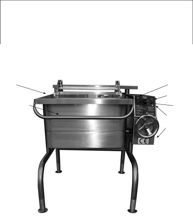
Cover |
Power Switch |
|
Indicator Light |
Cover Handle |
Thermostat |
|
Indicator Light |
|
Stainless Steel |
|
Console |
8 OM/SM-BPM-E CE
2. Assembly and Commissioning
2.1Electrical Supply
Before commissioning the appliance, ensure that the electrical installation has been performed in compliance with relevant regulations. See Paragraph 1.1.
WARNING
THIS APPLIANCE MUST BE EARTHED.
2.2Pre-Commissioning Check
a)Remove literature and packing materials from the interior and exterior of the unit.
b)Put enough water into the pan to cover the bottom to a depth of six to 12 mm. With the pan body in the horizontal position, note how the water lies in the pan, to confirm that the pan was leveled properly during installation.
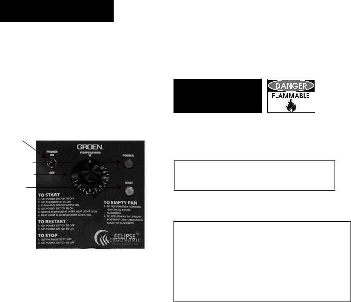
2.3Operating the Braising Pan
Power ON/OFF
Switch
Power ON
Neon (Red)
Thermostat
Heat ON Neon (Amber)
2.3.1 Heating Sequence
a)Put water in the pan (6 to 12 mm deep).
b)Check that electricity main is “ON”.
c)Turn the toggle switch (Electrical Cabinet) to the “ON” position. The red power neon will illuminate.
d)Turn the thermostat to the desired setting.
e)Observe that the elements are “ON” by the lighting of the amber heat neon.
f)To switch “OFF” the unit, put the toggle switch in the “OFF” position.
2.3.2 Checking Performance of Controls
a)Heat the unit as described in Paragraph 2.3.1, above. Check that the amber heat neon is glowing.
b)Turn the thermostat “OFF” and then “ON”. Check that the amber heat light goes out when the thermostat is turned o , and that it comes on when it is switched back on. Repeat 2 - 3 times.
c)Remove all water from the pan and thoroughly dry the pan.
d)Fill the pan with unused oil up to the mark in the pan. Oil level must not exceed 50mm (2").
WARNING
DO NOT OVERFILL WITH OIL
OR FIRE MAY RESULT!
e)Set the thermostat knob at “10" and allow the oil to heat up. Immerse a thermometer or thermocouple 25 mm below the oil surface at the center of the pan. Check that the temperature stabilizes at 190ºC, (± 5ºC).
CAUTION
THE TEMPERATURE MUST NOT EXCEED 200ºC OR THE HIGH LIMIT THERMOSTAT WILL TRIP.
f)If the unit fails to operate as described, the unit should be serviced by an Authorized Service Representative.
IMPORTANT
These appliances must be installed by a competent person in conformity with the installation and servicing instructions and national regulations in force at the time. Particular attention must be paid to the following: I.E.E. Regulations and Electrical Installations
Electricity at Work Regulations
Health and Safety at Work Act Fire Precautions Act
Local and National Building Regulations
2.4Instructions to Installer
IMPORTANT: After installing and commissioning the appliance, the User’s Instructions should be handed to the user or purchaser. Ensure that the instructions for heating, turning off, correct use and cleaning are properly understood.
OM/SM-BPM-E CE |
9 |

3. Service
3.1Servicing
Note: When replacing wiring connections refer to the wiring schematic in the unit or this manual.
3.1.1After Servicing
Check for correct operation as appropriate (see 2.3).
3.1.2Regular Servicing Procedures
The gears must be checked at regular intervals. The gear housing has been fitted for proper lubrication of moving parts. Since the gears do not run in oil, periodic lubrication with grease is essential. Frequency of lubrication depends on operating conditions, but should occur at least once every six months.
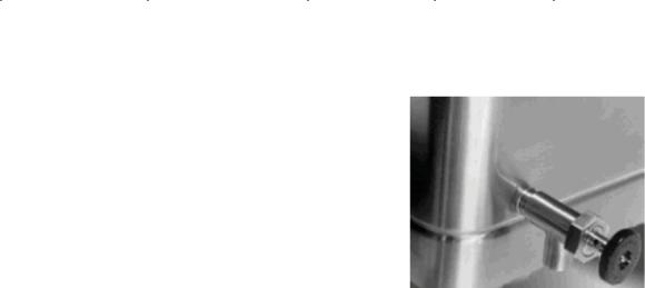
Groen recommends the use of a Number Two grade LGI lithium grease. Add grease through the Zerk fittings on the gear housing until grease flows out of the bearings around the trunnion shaft. Place a liberal amount of grease on the gear to cover the arc that is in contact with the worm gear (See Fig. 1).
Add grease through Zerk fitting
Fig. 1 |
Tilt switch & electrical insulating barrier |
WARNING
ELECTRICAL POWER MUST BE SHUT OFF BEFORE WORK IS DONE ON INTERNAL COMPONENTS
Fig. 2
3.3Removal of Tilt Switch
(Turn electricity main o )
a)Remove the electrical cabinet side panel (See Fig. 1).
b)Disconnect electrical leads from tilt switch.
c)Remove the two screws holding the switch to the bracket.
d)Remove tilt switch from control compartment.
e)Replace in reverse order. See CAUTION below.
CAUTION
BE SURE TO REPLACE THE ELECTRICAL INSULATING BARRIER
3.2Removal of Control Panels
3.2.1Removal of Electrical Cabinet Side Panel
a)Remove the two screws on lower edge of cover.
b)Remove the four screws at center of cover (See Fig. 2).
c)Remove the side panel.
d)Replace in reverse order.
3.2.2Removal of Electrical Cabinet Top Panel Assy.
a)Remove the side panel (per 3.2.1 above).
b)Remove one screw on back side of the top panel assembly.
c)Remove the two nuts holding the front edge of cover to the gearbox after side panel is removed.
d)Replace in reverse order.
3.4Removal of On/Off Switch
(Turn electricity main o )
a)Remove the electrical cabinet top cabinet top panel assembly and side panel as described in
Paragraph 3.2.2.
b)Disconnect electrical leads from On/O switch.
c)Undo and remove the retaining collar which secures the On/O switch to the outer surface of the electrical cabinet.
d)Withdraw the On/O switch from the control compartment.
e)Replace in reverse order.
10 OM/SM-BPM-E CE
 Loading...