


-3 Installation Manual")
OPERATOR MANUAL
IMPORTANT INFORMATION, KEEP FOR OPERATOR
This manual provides information for:
MODELS NHFP & NHFP(E) BRAISING PANS
·Stainless Steel
·Power Tilting
·Gas Heated
THIS MANUAL MUST BE RETAINED FOR FUTURE REFERENCE. READ, UNDERSTAND AND FOLLOW THE INSTRUCTIONS AND WARNINGS CONTAINED IN THIS MANUAL.
FOR YOUR SAFETY
Do not store or use gasoline or other flammable vapors and liquids in the vicinity of this or any other appliance.
POST IN A PROMINENT LOCATION
Instructions to be followed in the event user smells gas. This information shall be obtained by consulting your local gas supplier. As a minimum, turn off the gas and call your gas company and your authorized service agent. Evacuate all personnel from the area.
WARNING
Improper installation, adjustment, alteration, service or maintenance can cause property damage, injury or death. Readtheinstallation,operatingandmaintenanceinstructions thoroughly before installing or servicing this equipment.
NOTIFY CARRIER OF DAMAGE AT ONCE
It is the responsibility of the consignee to inspect the container upon receipt of same and to determine the possibility of any damage, including concealed damage. Unified Brands suggests that if you are suspicious of damage to make a notation on the delivery receipt. It will be the responsibility of the consignee to file a claim with the carrier. We recommend that you do so at once.
Manufacture Service/Questions 888-994-7636.
Information contained in this document is known to be current and accurate at the time of printing/creation. Unified Brands recommends referencing our product line websites, unifiedbrands.net, for the most updated product information and specifications.
PART NUMBER 121010 REV. B (10/07)
1055 Mendell Davis Drive
Jackson, MS 39272 888-994-7636, fax 888-864-7636 groen.com
|
IMPORTANT — READ FIRST — IMPORTANT |
CAUTION: |
SHIPPING STRAPS ARE UNDER TENSION AND CAN SNAP BACK WHEN CUT. |
CAUTION: |
UNIT WEIGHS 500 TO 600 LB. (230 TO 255 KG). FOR SAFE HANDLING, INSTALLER |
|
SHOULD OBTAIN HELP AS NEEDED, OR EMPLOY APPROPRIATE MATERIALS HANDLING |
|
EQUIPMENT (SUCH AS A FORKLIFT, DOLLY, OR PALLET JACKET) TO REMOVE THE UNIT |
|
FROM THE SKID AND MOVE IT TO THE PLACE OF INSTALLATION. |
WARNING: |
INSTALLATION OF THE BRAISING PAN MUST BE DONE BY PERSONNEL QUALIFIED TO |
|
WORK WITH GAS AND ELECTRICITY. IMPROPER INSTALLATION CAN RESULT IN INJURY |
|
TO PERSONNEL AND/OR DAMAGE TO EQUIPMENT. |
WARNING: |
THIS UNIT IS DESIGNED FOR COMMERCIAL USE. NEVER USE HOME OR RESIDENTIAL |
|
GRADE GAS CONNECTIONS. THEY DO NOT MEET GAS CODES AND COULD BE |
|
HAZARDOUS. |
DANGER: |
ELECTRICALLY GROUND THE UNIT AT THE TERMINAL PROVIDED. FAILURE TO GROUND |
|
UNIT COULD RESULT IN ELECTROCUTION AND DEATH. |
WARNING: |
KEEP THE APPLIANCE AREA FREE AND CLEAR OF COMBUSTIBLE MATERIALS. |
CAUTION: |
BE SURE ALL OPERATORS READ, UNDERSTAND AND FOLLOW THE OPERATING |
|
INSTRUCTIONS, CAUTIONS AND SAFETY INSTRUCTIONS CONTAINED IN THIS MANUAL. |
CAUTION: |
KEEP FLOORS IN BRAISING PAN WORK AREA CLEAN AND DRY. IF SPILLS OCCUR, |
|
CLEAN IMMEDIATELY TO AVOID THE DANGER OF SLIPS OR FALLS. |
WARNING: |
WHEN TILTING BRAISING PAN FOR PRODUCT TRANSFER: |
|
1) WEAR PROTECTIVE OVEN MITT AND PROTECTIVE APRON. |
|
2) USE CONTAINER DEEP ENOUGH TO CONTAIN AND MINIMIZE PRODUCT SPLASHING. |
|
3) PLACE CONTAINER ON STABLE, FLAT SURFACE, AS CLOSE TO PAN AS POSSIBLE. |
|
4) STAND TO SIDE OF PAN WHILE POURING — NOT DIRECTLY IN POUR PATH OF HOT |
|
CONTENTS. |
|
5) RETURN PAN BODY TO LEVEL POSITION AFTER CONTAINER IS FILLED OR |
|
TRANSFER IS COMPLETE. |
|
6) DO NOT OVER FILL CONTAINER. AVOID DIRECT SKIN CONTACT WITH HOT |
|
CONTAINER AND ITS CONTENTS. |
WARNING: |
DO NOT HEAT AN EMPTY PAN FOR MORE THAN 5 MINUTES AT A SETTING HIGHER |
|
THAN 300oF. |
WARNING: |
IF THE PAN CONTAINS ITEMS IN SAUCE OR MELTED FAT, THEY CAN SLIDE FORWARD |
|
SUDDENLY DURING TILTING AND CAUSE THE HOT LIQUID TO SPLASH OUT. |
WARNING: |
AVOID ALL DIRECT CONTACT WITH HOT FOOD OR WATER IN THE PAN. DIRECT |
|
CONTACT COULD RESULT IN SEVERE BURNS. |
WARNING: |
KEEP WATER AND SOLUTIONS OUT OF CONTROLS AND BURNERS. NEVER SPRAY OR |
|
HOSE THE CONTROL CONSOLE, OR ELECTRICAL CONNECTIONS. |
CAUTION: |
MOST CLEANERS ARE HARMFUL TO THE SKIN, EYES, MUCOUS MEMBRANES AND |
|
CLOTHING. PRECAUTIONS SHOULD BE TAKEN TO WEAR RUBBER GLOVES, GOGGLES |
|
OR FACE SHIELD AND PROTECTIVE CLOTHING. CAREFULLY READ THE WARNINGS AND |
|
FOLLOW THE DIRECTIONS ON THE LABEL OF THE CLEANER TO BE USED. |
WARNING: |
THE CONTROL BOX IS NOT WATERPROOF. TAKE CARE TO KEEP WATER AND |
|
CLEANING SOLUTIONS OUT OF THE BOX. NEVER HOSE OR SPRAY ELECTRICAL |
|
CONTROLS, CONNECTIONS OR CONTROL CONSOLE. |
WARNING: |
BEFORE REPLACING ANY PARTS, DISCONNECT THE UNIT FROM THE ELECTRIC POWER |
|
SUPPLY AND CLOSE THE MAIN GAS COCK. ALLOW FIVE MINUTES FOR UNBURNED GAS |
|
TO VENT. |
CAUTION: |
USE OF ANY REPLACEMENT PARTS OTHER THAN THOSE SUPPLIED BY GROEN OR |
|
AUTHORIZED DISTRIBUTORS CAN CAUSE INJURY TO THE OPERATOR AND DAMAGE TO |
|
THE EQUIPMENT AND WILL VOID ALL WARRANTIES. |
IMPORTANT: |
Service performed by other than factory authorized personnel will void all warranties. |
OM-NHFP
Table of Contents
IMPORTANT OPERATOR WARNINGS . . . . . . . . . . . . . . . . . . . . . . . . . . . . . . . . . . . . . . . . . . . . . . . . . . 2 EQUIPMENT DESCRIPTION . . . . . . . . . . . . . . . . . . . . . . . . . . . . . . . . . . . . . . . . . . . . . . . . . . . . . . . . . . 4 INSPECTION AND UNPACKING . . . . . . . . . . . . . . . . . . . . . . . . . . . . . . . . . . . . . . . . . . . . . . . . . . . . . . . 5 INSTALLATION . . . . . . . . . . . . . . . . . . . . . . . . . . . . . . . . . . . . . . . . . . . . . . . . . . . . . . . . . . . . . . . . . . . . . 5 INITIAL START-UP . . . . . . . . . . . . . . . . . . . . . . . . . . . . . . . . . . . . . . . . . . . . . . . . . . . . . . . . . . . . . . . . . . 6 OPERATION . . . . . . . . . . . . . . . . . . . . . . . . . . . . . . . . . . . . . . . . . . . . . . . . . . . . . . . . . . . . . . . . . . . . . . . 7 SEQUENCE OF OPERATION . . . . . . . . . . . . . . . . . . . . . . . . . . . . . . . . . . . . . . . . . . . . . . . . . . . . . . . . . . 9 CLEANING . . . . . . . . . . . . . . . . . . . . . . . . . . . . . . . . . . . . . . . . . . . . . . . . . . . . . . . . . . . . . . . . . . . . . . . . 10 MAINTENANCE . . . . . . . . . . . . . . . . . . . . . . . . . . . . . . . . . . . . . . . . . . . . . . . . . . . . . . . . . . . . . . . . . . . . 12 TROUBLESHOOTING . . . . . . . . . . . . . . . . . . . . . . . . . . . . . . . . . . . . . . . . . . . . . . . . . . . . . . . . . . . . . . . 12 PARTS LIST . . . . . . . . . . . . . . . . . . . . . . . . . . . . . . . . . . . . . . . . . . . . . . . . . . . . . . . . . . . . . . . . . . . . . . . 15 DIAGRAMS & SCHEMATICS . . . . . . . . . . . . . . . . . . . . . . . . . . . . . . . . . . . . . . . . . . . . . . . . . . . . . . . . . 18 REFERENCES . . . . . . . . . . . . . . . . . . . . . . . . . . . . . . . . . . . . . . . . . . . . . . . . . . . . . . . . . . . . . . . . . . . . . 20 MAINTENANCE LOG . . . . . . . . . . . . . . . . . . . . . . . . . . . . . . . . . . . . . . . . . . . . . . . . . . . . . . . . . . . . . . . . 21 WARRANTY . . . . . . . . . . . . . . . . . . . . . . . . . . . . . . . . . . . . . . . . . . . . . . . . . . . . . . . . . . . . . . . . . . . . . . . 22
OM-NHFP
Equipment Description
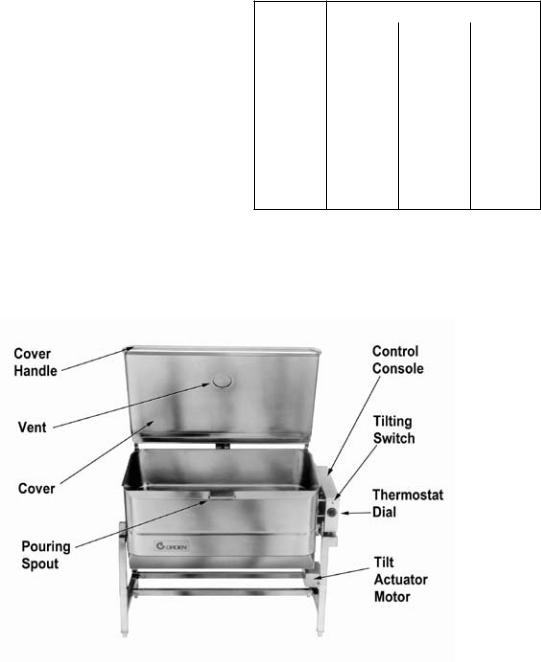
Groen NHFP and NHFP(E) Gas Fired Braising Pans provide a stainless steel pan equipped with heat transfer fins, burner/combustion chamber, power tilting mechanism, thermostatic controls, and hinged cover. The Braising Pan serves as a braising unit, griddle, fry pan, oven, kettle, bain marie, or food warmer and server. It can also be adapted for use as a steamer.
The pan body is constructed of heavy-duty stainless steel welded into one solid piece, with a polished interior and a semi-deluxe finish on the exterior. A pouring lip is welded into the front wall. The cooking surface is a stainless steel clad plate fitted with welded heat transfer fins that assure uniform heat transfer over the entire surface. The gas burner/combustion chamber supplies the heat.
The pan is tilted forward by an electrically powered actuator mechanism. A three-position switch on the front of the control console gives the operator positive, smoothly operating control of tilting. When the pan is tilted, the burners shut off automatically.
The thermostat provides automatic control of cooking temperature. The thermostat dial on the front of the control console turns the heat on or off and sets the pan temperature.
A vented, heavy gauge, one-piece, stainless steel cover with rear condensate drip shield on its underside is standard on the Braising Pan.
A fully enclosed, spring-type actuator counterbalances the cover to keep it opened or closed. The cover opens to the back and is hinged to the frame, so that it moves independently of the pan body.
Different ignition systems distinguish the basic models. Model NHFP uses a thermopilecontrolled, standing pilot flame to light the main burner. Model NHFP(E) ignites the main burner directly with an electrically heated hot surface igniter.
The following models and options are available:
Model |
Pan Body Dimensions, Inches |
|||
|
Left to |
Depth |
Firing |
|
|
Right |
Rate |
||
|
|
|||
NHFP-3 |
31¾ |
9 |
104,000 |
|
BTU/hr |
||||
|
|
|
||
NHFP(E)-3 |
31¾ |
9 |
104,000 |
|
BTU/hr |
||||
|
|
|
||
NHFP-4 |
41d |
9 |
144,000 |
|
BTU/hr |
||||
|
|
|
||
NHFP(E)-4 |
41d |
9 |
144,000 |
|
BTU/hr |
||||
|
|
|
||
Optional Equipment (Any Model)
1.Fill faucet with swing spout
2.Model REJ Steamer Insert
3.Caster mounting kit (factory installation only)
4.Two inch tangent draw-off
OM-NHFP

Inspection and Unpacking
The unit will arrive completely assembled, wrapped in protective plastic on a heavy skid, in a heavy cardboard carton. Immediately upon receipt, inspect the carton for damage. Report any apparent shipping damage or an incorrect shipment to the delivery agent.
When installation is to begin, get someone to assist in removing the carton. Lift it straight up and away from the unit. Do not simply raise it and push backwards - you will break the cover assembly vent handle. Write down the model number, serial number, and installation date of your unit, and keep this information for future reference. Space for these entries is provided at the top of the Service Log in this manual.
Cut the straps holding the unit on the skid, and lift the unit straight up off the skid.
CAUTION
SHIPPING STRAPS ARE UNDER TENSION AND CAN SNAP BACK WHEN CUT.
UNIT WEIGHS 500 TO 660 LB (230 TO 255 KG). FOR SAFE HANDLING, INSTALLER SHOULD OBTAIN HELP AS NEEDED, OR EMPLOY APPROPRIATE MATERIALS HANDLING EQUIPMENT (SUCH AS A FORKLIFT, DOLLY, OR PALLET JACKET) TO REMOVE THE UNIT FROM THE SKID AND MOVE IT TO THE PLACE OF INSTALLATION.
Installation
The NHFP or NHFP(E) Braising Pan should be installed in a ventilated room for efficient performance. Items which might obstruct or restrict the flow of air for combustion and ventilation must be removed. The area directly around the braising pan must be cleared of all combustible material.
WARNING
INSTALLATION OF THE BRAISING PAN MUST BE DONE BY PERSONNEL QUALIFIED TO WORK WITH GAS AND ELECTRICITY. IMPROPER INSTALLATION CAN RESULT IN INJURY TO PERSONNEL AND/OR DAMAGE TO EQUIPMENT.
1.Installation on combustible floors is allowed, with a minimum clearance to combustible and noncombustible construction of six inches at the rear, two inches at the left, and zero inches at the right.
2.Install the unit under a vent hood.
3.Level the unit by adjusting the bullet feet or floor flanges on the legs. Make sure the tilting mechanism has been run all the way to the horizontal position. Check levelness with a spirit level set on the bottom of the pan body. Anchor the rear
legs securely to the floor.
4.Complete the piping to the gas service by using 1/2 inch IPS pipe or approved equivalent.
WARNING:
THIS UNIT IS FOR COMMERCIAL USE. NEVER USE HOME OR RESIDENTIAL GRADE GAS CONNECTIONS. THEY DO NOT MEET GAS CODES AND COULD BE HAZARDOUS.
5.For a unit on casters, complete connection to the gas supply with connectors that comply with the standard for Connectors for Moveable Gas Appliances, ANSI Z21.69a-latest edition. Restrain movement of the unit by attaching a cable or chain to the eyelet (provided at the back of the frame) and anchoring the cable or chain to the wall or floor. Make the length and location of the cable such that the unit cannot pull on the gas connection while the cable is connected. The gas connection must be made with a quick disconnect device which complies with ANSI Z21.41b - latest edition.
OM-NHFP

WARNING
ELECTRICALLY GROUND THE UNIT AT THE TERMINAL PROVIDED. FAILURE TO GROUND UNIT COULD RESULT IN ELECTROCUTION AND DEATH.
6.Provide 115 Vac, 60 Hz, 5 Amp electrical service. Local codes and/or National codes should be observed in accordance with ANSI/NFPA70 - latest edition. AN ELECTRICAL GROUND IS REQUIRED. The Electrical Schematic is located on the inside of the Service Panel.
In Canada, provide electrical service in accordance with the Canadian Electrical Code, CSA-C22.1 Part 1, and/or local codes.
7.The installation must conform with the American National Standard Z223.1 - latest edition National Fuel Gas Code. The unit should be installed in an adequately ventilated room with an adequate air supply. The best ventilation will use a vent hood and exhaust fan. DO NOT obstruct the flue or vent.
8.In Canada, the installation must conform to CAN/CGA B149, Installation Codes for Gas Appliances and Equipment, and/or local codes.
9.The braising pan and its shutoff valve must be disconnected from the gas supply piping system during any testing at pressures in excess of ½ psig (3.48 kPa). The appliance must be isolated from the gas supply piping system by closing its individual manual shutoff valve during any pressure testing of the gas supply piping system at test pressures equal to or less than ½ psig (3.48 kPa).
9.Space for servicing and operation is required. DO NOT block any air intake spacing to the combustion chamber or obstruct air flow.
10.After the pan has been connected to the gas supply, check each gas joint for leaks. Use a thick soap solution or other suitable leak detector. Do not use a flame to check for leaks.
Initial Start-Up
Now that the Braising Pan has been installed, you should test it to ensure that the unit is operating correctly.
1.Remove all literature and packing materials from the interior and exterior of the unit.
2.Put enough water into the pan to cover the bottom to a depth of 1/4 to 1/2 inch. With the tilting mechanism run to the horizontal position, note how the water lies in the pan, to confirm that the pan was leveled properly during installation.
3.Following "To Start Pan" instructions for your pan model, begin heating the water at a thermostat setting of 235oF. At this setting, heating should continue until the water boils.
4.To shut down the unit, turn the thermostat dial to "OFF".
WARNING
WATER IS EXTREMELY HOT AND CAN CAUSE SEVERE BURNS. AVOID WATER WHEN EMPTYING UNIT.
5.Press the power tilt switch down to pour out the water and to confirm that the pan body can be tilted from horizontal to vertical. Pull the switch up to lower the pan.
If the unit functions as described above, it is ready for use. If it does not, contact your local Groen Authorized Service Agency.
OM-NHFP
Operation
A. Controls
Operator controls for the Braising Pans are:
1.The thermostat dial, located on the control console to the right of the pan body. This dial is used to turn the thermostat on or off and to set the thermostat for pan temperatures between 175o and 425oF.
2.The power tilt switch, also located on the control console, which is used to raise or lower the pan body
3.The main supply gas cock, installed on the gas line to the unit.
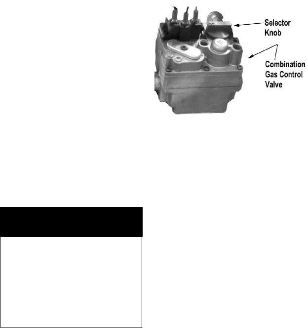
4.For NHFP only, the manual valve on the Combination Gas Control Valve, which is located under the pan on the gas line to the burner manifold. This valve selects settings of "OFF", "PILOT", or "ON" for the Combination Control.
Control for Thermopile System — Model NHFP
(b)Open the main supply gas cock.
(c)Tilt the pan, so the pilot burner is easier to reach.
B. Operating Procedure
WARNING
KEEP THE APPLIANCE AREA FREE AND CLEAR OF COMBUSTIBLE MATERIALS.
CAUTION
BE SURE ALL OPERATORS READ, UNDERSTAND AND FOLLOW THE OPERATING INSTRUCTIONS, CAUTIONS AND SAFETY INSTRUCTIONS CONTAINED IN THIS MANUAL.
KEEP FLOORS IN BRAISING PAN WORK AREA CLEAN AND DRY. IF SPILLS OCCUR, CLEAN IMMEDIATELY TO AVOID THE DANGER OF SLIPS OR FALLS.
1.For Model NHFP with Thermopile System a. To Start Pan
(1)Set thermostat to "OFF".
(2)Light gas pilot.
(a)Set knob on Combination Gas Control Valve to "OFF" by depressing the knob slightly and turning it clockwise.
(d)Hold a lighted match at the pilot burner, while you depress the knob on the Combination Control and turn it counterclockwise to the "PILOT" position. Continue to hold the knob down for 60 seconds.
(e)Release the knob. The pilot flame should stay lighted.
(f)Turn the knob counterclockwise to "ON".
(3)Turn the thermostat dial to the desired temperature.
b.To Shut Off Pan
(1)Set the thermostat dial to "OFF".
(2)To turn off the gas pilot, depress the knob on the Combination Control and turn it clockwise to "OFF".
c.To Relight Pilot
(1)Close the main supply gas cock.
OM-NHFP

(2)Set the thermostat to "OFF".
(3)Depress the knob on the Combination Control and turn it clockwise to "OFF".
(4)Wait 5 minutes, then proceed as instructed at "To Start Pan" above.
2.For Model NHFP(E) with Hot Surface Igniter
a.To Start Pan
(1)DO NOT attempt to light the burner with a flame.
(2)Turn on the electrical service to the unit.
(3)Turn the main supply gas cock ON (handle parallel to the gas pipe).
(4)Turn the thermostat dial to the desired temperature setting.
b.To Turn Off Pan
(1)Set the thermostat to "OFF".
(2)For a prolonged shut-off period:
(a)Set the thermostat to "OFF".
(b)Turn the main gas cock OFF
(handle at right angles to the gas pipe).
(c)Disconnect the electrical power from the unit.
WARNING
WHEN TILTING BRAISING PAN FOR PRODUCT TRANSFER:
1)WEAR PROTECTIVE OVEN MITT AND PROTECTIVE APRON.
2)USE CONTAINERS DEEP ENOUGH TO CONTAIN AND MINIMIZE PRODUCT SPLASHING
3)PLACE CONTAINER ON A STABLE, FLAT SURFACE, AS CLOSE TO THE BRAISING PAN AS POSSIBLE.
4)STAND TO THE SIDE OF THE PAN WHILE POURING — NOT DIRECTLY IN THE POUR PATH OF HOT CONTENTS.
5)RETURN PAN BODY TO UPRIGHT POSITION AFTER CONTAINER IS FILLED OR TRANSFER IS COMPLETE.
6)DO NOT OVERFILL CONTAINER. AVOID DIRECT SKIN CONTACT WITH HOT CONTAINER AND CONTENTS
3.To Tilt Either Model
a.Press the power tilt switch down to raise the pan or up to lower the pan.
b.The spring loaded switch will return to the OFF (middle) position when you release it.
c.If the power tilt mechanism stops working (see the Troubleshooting section) and you must raise or lower the pan body without delay, you can tilt the body by hand. Fit the provided hand crank onto the slotted shaft end that sticks out of the actuator motor (the end facing the front of the unit). Turn the crank clockwise to lower the pan or counterclockwise to raise the pan. It may take several minutes to crank the pan to the desired position, but the operation can be speeded up by substituting a reversible electric drill with screwdriver bit in place of the hand crank.
OM-NHFP
 Loading...