


IMPORTANT INFORMATION * KEEP FOR OPERATOR * IMPORTANT INFORMATION
OPERATOR MANUAL |
OM-HFP |
Part Number 121023 |
DOMESTIC |
MODELS: HFP/1,HFP/1E,
MW/HFP/1,MW/HFP/1E
HFP/2, HFP/2E MW/HFP/2,
MW/HFP/2E
Braising Pans
Stainless Steel
Manual Tilting Gas
Heated
THIS MANUAL MUST BE RETAINED FOR FUTURE REFERENCE. READ, UNDERSTAND AND FOLLOW THE INSTRUCTIONS AND WARNINGS CONTAINED IN THIS MANUAL.

OM-HFP
CAUTION: SHIPPING STRAPS ARE UNDER TENSION AND CAN SNAP BACK WHEN CUT.
CAUTION: UNIT WEIGHS 370 TO 560 LB. (165 TO 255 KG). FOR SAFE HANDLING, INSTALLER
SHOULD OBTAIN HELP AS NEEDED, OR EMPLOY APPROPRIATE MATERIALS HANDLING EQUIPMENT (SUCH AS A FORKLIFT, DOLLY, OR PALLET JACKET) TO REMOVE THE UNIT FROM THE SKID AND MOVE IT TO THE PLACE OF INSTALLATION.
WARNING: INSTALLATION OF THE BRAISING PAN MUST BE DONE BY PERSONNEL QUALIFIED TO WORK WITH GAS AND ELECTRICITY. IMPROPER INSTALLATION CAN RESULT IN INJURY TO PERSONNEL AND/OR DAMAGE TO EQUIPMENT.
WARNING: THIS UNIT IS DESIGNED FOR COMMERCIAL USE. NEVER USE HOME OR RESIDENTIAL GRADE GAS CONNECTIONS. THEY DO NOT MEET GAS CODES AND COULD BE HAZARDOUS.
DANGER: ELECTRICALLY GROUND THE UNIT AT THE TERMINAL PROVIDED. FAILURE TO GROUND UNIT COULD RESULT IN ELECTROCUTION AND DEATH.
WARNING: KEEP THE APPLIANCE AREA FREE AND CLEAR OF COMBUSTIBLE MATERIALS.
CAUTION: BE SURE ALL OPERATORS READ, UNDERSTAND AND FOLLOW THE OPERATING INSTRUCTIONS, CAUTIONS AND SAFETY INSTRUCTIONS CONTAINED IN THIS MANUAL.
CAUTION: KEEP FLOORS IN BRAISING PAN WORK AREA CLEAN AND DRY. IF SPILLS OCCUR, CLEAN IMMEDIATELY TO AVOID THE DANGER OF SLIPS OR FALLS.
WARNING: WHEN TILTING BRAISING PAN FOR PRODUCT TRANSFER:
1)USE CONTAINER DEEP ENOUGH TO CONTAIN AND MINIMIZE PRODUCT SPLASHING.
2)PLACE CONTAINER ON STABLE, FLAT SURFACE, AS CLOSE TO PAN AS POSSIBLE.
3)STAND TO SIDE OF PAN WHILE POURING - NOT DIRECTLY IN POUR PATH OF HOT CONTENTS.
4)RETURN PAN BODY TO LEVEL POSITION AFTER CONTAINER IS FILLED OR TRANSFER IS COMPLETE.
5)DO NOT OVER FILL CONTAINER. AVOID DIRECT SKIN CONTACT WITH HOT CONTAINER AND ITS CONTENTS.
WARNING: DO NOT HEAT AN EMPTY PAN FOR MORE THAN 5 MINUTES AT A SETTING HIGHER THAN 300°F. WARNING: IF THE PAN CONTAINS ITEMS IN SAUCE OR MELTED FAT, THEY CAN SLIDE FORWARD SUDDENLY
DURING TILTING AND CAUSE THE HOT LIQUID TO SPLASH OUT.
WARNING: AVOID ALL DIRECT CONTACT WITH HOT FOOD OR WATER IN THE PAN. DIRECT CONTACT COULD RESULT IN SEVERE BURNS.
WARNING: KEEP WATER AND SOLUTIONS OUT OF CONTROLS AND BURNERS. NEVER SPRAY OR HOSE THE CONTROL CONSOLE, OR ELECTRICAL CONNECTIONS.
CAUTION: MOST CLEANERS ARE HARMFUL TO THE SKIN, EYES, MUCOUS MEMBRANES AND
CLOTHING. PRECAUTIONS SHOULD BE TAKEN TO WEAR RUBBER GLOVES, GOGGLES OR FACE SHIELD AND PROTECTIVE CLOTHING. CAREFULLY READ THE WARNINGS AND FOLLOW THE DIRECTIONS ON THE LABEL OF THE CLEANER TO BE USED.
WARNING: THE CONTROL BOX IS NOT WATERPROOF. TAKE CARE TO KEEP WATER AND
CLEANING SOLUTIONS OUT OF THE BOX. NEVER HOSE OR SPRAY ELECTRICAL CONTROLS, CONNECTIONS OR CONTROL CONSOLE.
WARNING: BEFORE REPLACING ANY PARTS, DISCONNECT THE UNIT FROM THE ELECTRIC POWER SUPPLY AND CLOSE THE MAIN GAS COCK. ALLOW FIVE MINUTES FOR UNBURNED GAS TO VENT.
CAUTION: USE OF ANY REPLACEMENT PARTS OTHER THAN THOSE SUPPLIED BY GROEN OR AUTHORIZED DISTRIBUTORS CAN CAUSE INJURY TO THE OPERATOR AND DAMAGE TO THE EQUIPMENT AND WILL VOID ALL WARRANTIES.
IMPORTANT: Service performed by other than factory authorized personnel will void all warranties.
2
OM-HFP
Table of Contents
IMPORTANT OPERATOR WARNINGS (READ FIRST) |
2 |
EQUIPMENT DESCRIPTION |
4 |
INSPECTION AND UNPACKING |
6 |
INSTALLATION |
7 |
INITIAL START-UP |
8 |
OPERATION |
9 |
SEQUENCE OF OPERATION |
11 |
CLEANING |
12 |
MAINTENANCE |
14 |
REFERENCES |
14 |
TROUBLESHOOTING |
15 |
PARTS LIST |
18 |
DIAGRAMS & SCHEMATICS |
23 |
MAINTENANCE LOG |
26 |
3
OM-HFP
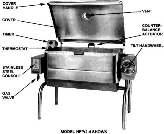
Equipment Description
Groen Gas Heated Braising Pans provide a stainless steel pan equipped with patented heat transfer fins, burner/combustion chamber, handoperated tilting mechanism, thermostatic controls, and hinged cover. The Braising Pan serves as braising unit, griddle, fry pan, oven, kettle, bain-marie, or food warmer and server, and it can be adapted for use as a steamer.
The pan body is made from heavy -duty stainless steel welded into one solid piece, with a polished interior and exterior. A pouring lip is welded to the front wall. The cooking surface is a stainless steel clad plate fitted with welded heat transfer fins which assure uniform heat transfer over the entire surface. The gas burner/combustion chamber supplies the heat.
An easily-operated worm and gear mechanism tilts the pan and provides precise control for pouring or dumping the contents of the pan. This hand-wheel controlled mechanism is located in a stainless steel console to the right of the pan body. To assist cleaning, the pan body can be tilted past the vertical position. When the pan is tilted, the burners shut off automatically.
The thermostat provides automatic control of cooking temperature. Operating the thermostat dial on the front of the control console turns the heat on or off and sets the pan temperature.
A vented, heavy gauge, one-piece, stainless steel cover with a condensate drip shield on the rear edge is standard on the Braising Pan. A fully enclosed, spring type actuator counter-balances the cover to keep it in either the opened or closed position. The cover opens to the back and is hinged to the frame, so it moves independently of the pan body.
The basic models differ in their mounting and their ignition systems. Models HFP/1, HFP/1E, HFP/2, and HFP/2E are mounted on an open-leg frame fabricated from tubular stainless steel. MW/HFP/1, MW/HFP/1E, MW/HFP/2, and MW/HFP/2E are designed to be wall-mounted with side support arms and a splashback.
Models HFP/1, HFP/2, MW/HFP/1, and MW/HFP/2 have a standing-flame pilot light that ignites the main burner. Models HFP/1E, HFP/2E, MW/HFP/1E, and MW/HFP/2E have ignition systems that use a hot surface igniter.
Model |
Pan Dimensions |
Ignition |
||
|
|
|||
L to R |
Depth |
|||
|
|
|||
|
|
|
|
|
HFP/1-2 |
24 5/8" |
7" |
Flame |
|
MW/HFP/1-2 |
(62.5cm) |
(18cm) |
||
|
||||
|
|
|
|
|
HFP/1E-2 |
24 5/8" |
7" |
Spark |
|
MW/HFP/1E-2 |
(62.5 cm) |
(18cm) |
||
|
||||
|
|
|
|
|
HFP/1-3 |
31 5/8" |
7" or 9" |
Flame |
|
MW/HFP/1-3 |
(80 cm) |
(18 or 23cm) |
||
|
||||
|
|
|
|
|
HFP/1E-3 |
31 5/8" |
7" or 9" |
Spark |
|
MW/HFP/1E-3 |
(80 cm) |
(18 or 23cm) |
||
|
||||
|
|
|
|
|
HFP/1-4 |
41 5/8" |
7" or 9" |
Flame |
|
MW/HFP/1-4 |
(1.06m) |
(18 or 23cm) |
||
|
||||
|
|
|
|
|
HFP/1E-4 |
41 5/8" |
7" or 9" |
Spark |
|
MW/HFP/1E-4 |
(1.06m) |
(18 or 23cm) |
||
|
||||
|
|
|
|
|
HFP/2-2 |
24 5/8" |
7" or 9" |
Flame |
|
MW/HFP/2-2 |
(62.5cm) |
(18 or 23cm) |
||
|
||||
|
|
|
|
|
HFP/2E-2 |
24 5/8" |
7" or 9" |
Coil |
|
MW/HFP/2E-2 |
(62.5 cm) |
(18 or 23cm) |
||
|
||||
|
|
|
|
|
HFP/2-3 |
31 5/8" |
7" or 9" |
Flame |
|
MW/HFP/2-3 |
(80 cm) |
(18 or 23cm) |
||
|
||||
|
|
|
|
|
HFP/2E-3 |
31 5/8" |
7" or 9" |
Coil |
|
MW/HFP/2E-3 |
(80 cm) |
(18 or 23cm) |
||
|
||||
|
|
|
|
|
HFP/2-4 |
41 5/8" |
7" or 9" |
Flame |
|
MW/HFP/2-4 |
(1.06m) |
(18 or 23cm) |
||
|
||||
|
|
|
|
|
HFP/2E-4 |
41 5/8" |
7" or 9" |
Coil |
|
MW/HFP/2E-4 |
(1.06m) |
(18 or 23cm) |
||
|
||||
|
|
|
|
|
Options available with the listed models are:
1.Fill faucet with swing spout.
2.Caster mounting kit.
3.Fold-down work tray (pan support) mounted on
left or right side.
4.2" Tangent draw-off
5.Model REJ Steamer Insert set.
6.Steamer pan Carrier.
7.Quick gas disconnect with restraining cable.
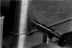
Optional Tangent Draw-Off
4
|
|
|
OM-HFP |
|
|
Performance Data |
|
||
|
|
|
|
|
OLD MODELS |
FIRING RATE |
NEW MODELS |
FIRING RATE |
|
|
|
|
|
|
HFP/1-2 |
73,000 BTU/hr |
HFP/2-2 |
80,000 BTU/hr |
|
HFP/1E-2 |
HFP/2E-2 |
|||
|
|
|||
|
|
|
|
|
HFP/1-3 |
90,000 BTU/hr |
HFP/2-3 |
104,000 BTU/hr |
|
HFP/1-E-3 |
HFP/2E-3 |
|||
|
|
|||
|
|
|
|
|
HFP/1-4 |
120,000 BTU/hr |
HFP/2-4 |
144,000 BTU/hr |
|
HFP/1E-4 |
HFP/2E/4 |
|||
|
|
|||
|
|
|
|
|
MW/HFP/1-2 |
62,000 BTU/hr |
MW/HFP/2-2 |
80,000 BTU/hr |
|
MW/HFP/1E-2 |
MW/HFP/2E-2 |
|||
|
|
|||
|
|
|
|
|
MW/HFP/11-3 |
90,000 BTU/hr |
MW/HFP/2-3 |
104,000 BTU/hr |
|
MW/HFP/1E-3 |
MW/HFP/2E-3 |
|||
|
|
|||
|
|
|
|
|
MW/HFP/1-4 |
120,000 BTU/hr |
MW/HFP/2-4 |
144,000 BTU/hr |
|
MW/HFP/1E-4 |
MW/HFP/2E-4 |
|||
|
|
|||
|
|
|
|
|
NOTE: MW/HFP/1 or MW/HFP/2 Braising Pan is similar to above pan, but is without legs. Wall brackets are provided. Some console dimensions are changed, but basic information and parts apply.
5
OM-HFP
Inspection and Unpacking
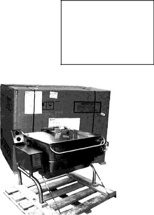
The unit will arrive completely assembled, wrapped in protective plastic on a heavy skid, in a heavy cardboard carton. Immediately upon receipt, inspect the carton for damage. Report any apparent shipping damage or an incorrect shipment to the delivery agent.
When installation is to begin, get someone to assist in removing the carton. Lift it straight up and away from the unit. Do not simply raise it and push backwards - you will break the cover assembly vent handle. Write down the model number, serial number, and installation date of your unit, and keep this information for future reference. Space for these entries is provided at the top of the Service Log in this manual.
Cut the straps holding the unit on the skid, and lift the unit straight up off the skid.
CAUTION
SHIPPING STRAPS ARE UNDER TENSION AND CAN SNAP BACK WHEN CUT.
UNIT WEIGHS 370 TO 560 LB (170 TO 255
KG). FOR SAFE HANDLING, INSTALLER SHOULD OBTAIN HELP AS NEEDED, OR EMPLOY APPROPRIATE MATERIALS HANDLING EQUIPMENT (SUCH AS A FORKLIFT, DOLLY, OR PALLET JACKET) TO REMOVE THE UNIT FROM THE SKID
AND MOVE IT TO THE PLACE OF INSTALLATION.
The unit is strapped to a skid, and shipped in a heavy cardboard carton.
6

OM-HFP
Installation
The Braising Pan should be installed in a ventilated room for efficient performance. Items which might obstruct or restrict the flow of air for combustion and ventilation must be removed. The area directly around the braising pan must be cleared of all combustible material.
WARNING INSTALLATION OF THE BRAISING PAN MUST BE DONE BY PERSONNEL QUALIFIED TO WORK WITH GAS AND ELECTRICITY. IMPROPER INSTALLATIN CAN RESULT IN INJURY TO PERSONNEL AND/OR DAMAGE TO EQUIPMENT.
1.Installation on combustible floors is
allowed, with a minimum clearance to combustible and noncombustible construction of six inches at the rear, and zero inches at the sides. will be attached, following the accompanying instructions regarding anchoring and location.
2.Install the unit under a vent hood.
3.For Open Leg Models (HFP/1, HFP/1E, HFP/2, HFP/2E):
Level the unit by adjusting the bullet feet or floor flanges on the legs. Be sure the tilting mechanism has been turned all the way to the horizontal position. Check levelness with a spirit level set on the bottom of the pan body. Anchor the rear legs securely to the floor if floor flanges are ordered or required.
4.Wall-Mounted Models (MW/HFP/1, MW/HFP/1E, MW/HFP/2, MW/HFP/2E
a.Install the provided "chair carrier" frame in the wall to which the pan
Typical Multi-Unit Chair Carrier
b.Stub in the electrical service and service and gas supply line so that they will be aligned with the control console on the left side of the pan once the pan is mounted.
c.Mount the pan on the protruding studs of the chair carrier. Make sure the
bottom of the pan body is level, before you proceed to the next step. To prevent sanitation problems, seal the junction between pan and the wall with an NSF-approved material such as "Silastic"
5.Complete the piping to the gas service by using % inch IPS pipe or approved equivalent.
WARNING:
THIS UNIT IS FOR COMMERCIAL USE. NEVER USE HOME OR RESIDENTIAL GRADE GAS CONNECTIONS. THEY DO NOT MEET GAS CODES AND COULD BE HAZARDOUS.
6.For a unit on casters, complete connection to the gas supply with connectors that comply with the
standard for Connectors for Moveable Gas Appliances, ANSI Z21,69a-latest edition. Restrain movement of the unit by attaching a cable or chain to the eyelet (provided at the back of the frame) and anchoring the cable or chain to the wall or floor. Make the length and location of the cable such that the unit cannot pull on the gas connection while the cable is connected.
7.The gas connection must be made with a quick disconnect device compliant with
ANSI Z21.41b - latest edition.
7

OM-HFP
8.For models with hot surface ignition, provide 115 VAC, 60 HZ, 1 phase, 5 AMP electrical service through the rear of the electrical console. Local codes and/or The National Electrical Code should be observed in accordance with ANSI/NFPA70, latest edition. AN ELECTRICAL GROUND IS REQUIRED. The
electrical schematic is located on the inside of the service panel. In Canada, provide electrical service in accordance with the Canadian Electrical Code, CSA-C22.1 Part 1 and/or local codes.
9.The installation must conform with local codes or with the American
National Standard Z223, latest edition, National Fuel Gas Code. The pan should be installed in an adequately ventilated room with a provision for adequate air supply to the unit. The best ventilation will use a vent hood and exhaust fan. DO NOT obstruct the flue or vent duct after installation. In Canada, installation must conform to CAN/CGA B149 Installation Codes for Gas Appliances and Equipment and/or local codes.
10.Adequate space for proper servicing and operation is required. DO NOT block any air intake spacings to the combustion chamber or obstruct air flow.
11.After the pan has been connected to the gas supply, check all gas joints for leaks. A soap solution or other suitable leak detector should be used. Do not use flame to check for leaks.
12.The appliance and its individual shutoff valve must be protected
from the gas supply piping system during any pressure testing of that system at test pressures in excess of 1/2 PSI (3.45 kPa). The appliance can be isolated from the gas supply piping system by closing its individual manual shutoff valve during any pressure testing of the gas supply piping system.
Initial Start-Up
Now that your Braising Pan has been installed, you should test it to ensure that the unit is operating correctly.
1.Remove literature and packing materials from the interior and exterior of the unit.
2.Put enough water into the pan to cover the bottom to a depth of % to 1/2 inch. With
the pan body in the horizontal position, note how the water lies in the pan, to confirm that the pan was leveled properly during installation.
3.Following "To Start Pan" instructions for your pan model, begin heating the water
at a thermostat setting of 235°F. At this setting, heating should continue until the water boils.
4.To shut down the unit, turn the thermostat dial to “OFF”.
WARNING
WATER IS EXTREMELY HOT AND CAN CAUSE SEVERE BURNS. AVOID CONTACT WITH HOT WATER WHEN EMPTYING UNIT.
5.Turn the tilting handwheel clockwise to pour out the water and to confirm that the pan body can be tilted smoothly from horizontal to vertical.
If the unit functions as described above, it is ready for use. If it does not, contact your local Groen Authorized Service Agency.
8
OM-HFP
Operation
A. Controls
Operator controls for the Braising Pans are:
1.The thermostat dial, located on the control console to the left of the pan body. This dial is used to turn the thermostat on or off and to set the thermostat for pan temperatures between 175° and 425°F.
2.The main supply gas valve, installed on the gas line to the unit.
3.For HFP/1, MW/HFP/1, HFP/2, and MW/HFP/2, the manual valve is on the Combination Gas Control Valve, which is located under the pan on the gas line to the burner manifold. This valve selects settings of "OFF", "PILOT", or "ON" for the Combination Control.
4. Mechanical 0-60 minute bell timer.
B. Operating Procedure
WARNING
KEEP THE APPLIANCE AREA FREE AND CLEAR OF COMBUSTIBLE MATERIALS.
CAUTION
BE SURE ALL OPERATORS READ, UNDERSTAND AND FOLLOW THE OPERATING INSTRUCTIONS. CAUTIONS AND SAFETY INSTRUCTIONS CONTAINED IN THIS MANUAL.
KEEP FLOORS IN BRAISING PAN WORK AREA CLEAN AND DRY. IF SPILLS OCCUR, CLEAN IMMEDIATELY TO AVOID THE DANGER OF SLIPS OR FALLS.
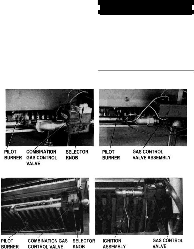
HFP/1 WITH THERMOPILE IGNITION |
HFP/1 WITH ELECTRONIC SPARK IGNITION |
HFP/2 WITH THERMOPILE IGNITION |
HFP/2 WITH GLOW COIL IGNITION |
9
 Loading...