


IMPORTANTINFORMATION KEEPFOROPERATOR IMPORTANTINFORMATION
OPERATOR MANUAL
Part Number 148733 Rev. B
Models: TDB and TDBC
Steam Jacketed Kettle
Self-Contained
Electrically heated
Table top mounted
Tilting
Model TDBC
OM-TDB
DOMESTIC / GOVERNMENT
Model TDB
THIS MANUAL MUST BE RETAINED FOR FUTURE REFERENCE. READ, UNDERSTAND AND FOLLOW THE INSTRUCTIONS AND WARNINGS CONTAINED IN THIS MANUAL.
FOR YOUR SAFETY
DO NOT STORE OR USE GASOLINE OR OTHER FLAMMABLE VAPORS AND LIQUIDS IN THE VICINITY OF THIS OR ANY OTHER APPLIANCE.

OM-TDB
|
|
|
IMPORTANT — READ FIRST — IMPORTANT |
CAUTION: |
BE SURE ALL OPERATORS READ, UNDERSTAND AND FOLLOW THE OPERATING |
|
INSTRUCTIONS, CAUTIONS, AND SAFETY INSTRUCTIONS CONTAINED IN THIS |
|
MANUAL. |
WARNING: |
THIS UNIT IS INTENDED FOR USE IN THE COMMERCIAL HEATING, COOKING AND |
|
HOLDING OF WATER AND FOOD PRODUCTS, PER THE INSTRUCTIONS |
|
CONTAINED IN THIS MANUAL. ANY OTHER USE COULD RESULT IN SERIOUS |
|
PERSONAL INJURY OR DAMAGE TO THE EQUIPMENT AND WILL VOID |
|
WARRANTY. |
WARNING: |
KETTLE MUST BE INSTALLED BY PERSONNEL QUALIFIED TO WORK WITH |
|
ELECTRICITY. IMPROPER INSTALLATION CAN RESULT IN INJURY TO |
|
PERSONNEL AND/OR DAMAGE TO EQUIPMENT. |
DANGER: |
ELECTRICALLY GROUND THE UNIT AT THE TERMINAL PROVIDED. FAILURE TO |
|
GROUND UNIT COULD RESULT IN ELECTROCUTION AND DEATH. |
WARNING: |
AVOID ALL DIRECT CONTACT WITH HOT EQUIPMENT SURFACES. DIRECT SKIN |
|
CONTACT COULD RESULT IN SEVERE BURNS. |
WARNING: |
AVOID ALL DIRECT CONTACT WITH HOT FOOD OR WATER IN THE KETTLE. |
|
DIRECT CONTACT COULD RESULT IN SEVERE BURNS. |
CAUTION: |
DO NOT OVER FILL THE KETTLE WHEN COOKING, HOLDING OR CLEANING. |
|
KEEP LIQUIDS A MINIMUM OF 2-3” (5-8 cm) BELOW THE KETTLE BODY RIM TO |
|
ALLOW CLEARANCE FOR STIRRING, BOILING AND SAFE PRODUCT TRANSFER. |
WARNING: |
TAKE SPECIAL CARE TO AVOID CONTACT WITH HOT KETTLE BODY OR HOT |
|
PRODUCT WHEN ADDING INGREDIENTS, STIRRING OR TRANSFERRING |
|
PRODUCT TO ANOTHER CONTAINER. |
WARNING: |
DO NOT STAND ON OR APPLY UNNECESSARY WEIGHT OR PRESSURE ON THE |
|
KETTLE FRONT OR POURING LIP. THIS COULD RESULT IN OVERLOAD AND |
|
FAILURE OF THE TILT MECHANISM, AND POSSIBLE SERIOUS INJURY AND |
|
BURNS TO THE OPERATOR AND OTHERS. |
WARNING: |
WHEN TILTING KETTLE FOR PRODUCT TRANSFER: |
|
1) WEAR PROTECTIVE OVEN MITT AND PROTECTIVE APRON. |
|
2) USE CONTAINER DEEP ENOUGH TO CONTAIN AND MINIMIZE PRODUCT |
|
SPLASHING. |
|
3) PLACE CONTAINER ON STABLE, FLAT SURFACE, AS CLOSE TO KETTLE AS |
|
POSSIBLE. |
|
4) STAND TO LEFT OR RIGHT SIDE OF KETTLE (DEPENDING ON TILTING |
|
HANDLE PLACEMENT) WHILE POURING . DO NOT STAND DIRECTLY IN POUR |
|
PATH OF HOT CONTENTS. |
|
5) POUR SLOWLY, MAINTAIN CONTROL OF KETTLE BODY HANDLE AT ALL |
|
TIMES, AND RETURN KETTLE BODY TO UPRIGHT POSITION AFTER |
|
CONTAINER IS FILLED OR TRANSFER IS COMPLETE. |
|
6) DO NOT OVER FILL CONTAINER. AVOID DIRECT SKIN CONTACT WITH HOT |
|
CONTAINER AND ITS CONTENTS. |
CAUTION: |
KEEP FLOORS IN FRONT OF KETTLE WORK AREACLEAN AND DRY. IF SPILLS |
|
OCCUR, CLEAN IMMEDIATELY, TO AVOID SLIPS OR FALLS. |
WARNING: |
FAILURE TO CHECK PRESSURE RELIEF VALVE OPERATION PERIODICALLY |
|
COULD RESULT IN PERSONAL INJURY AND/OR DAMAGE TO EQUIPMENT. |
WARNING: |
WHEN TESTING, AVOID ANY EXPOSURE TO THE STEAM BLOWING OUT OF THE |
|
PRESSURE RELIEF VALVE. DIRECT CONTACT COULD RESULT IN SEVERE |
|
BURNS. |
WARNING: |
TO AVOID INJURY, READ AND FOLLOW ALL PRECAUTIONS STATED ON THE |
|
LABEL OF THE WATER TREATMENT COMPOUND. |
WARNING: |
BEFORE REPLACING ANY PARTS, DISCONNECT THE UNIT FROM THE ELECTRIC |
|
POWER SUPPLY. |
2

OM-TDB
|
IMPORTANT — READ FIRST — IMPORTANT |
WARNING: |
KEEP WATER AND SOLUTIONS OUT OF CONTROLS AND ELECTRICAL |
|
EQUIPMENT. NEVER USE A HIGH PRESSURE HOSE TO CLEAN KETTLE |
|
SURFACES. |
CAUTION: |
MOST CLEANERS ARE HARMFUL TO THE SKIN, EYES, MUCOUS MEMBRANES |
|
AND CLOTHING. PRECAUTIONS SHOULD BE TAKEN. WEAR RUBBER GLOVES, |
|
GOGGLES OR FACE SHIELD AND PROTECTIVE CLOTHING. CAREFULLY READ |
|
THE WARNINGS AND FOLLOW THE DIRECTIONS ON THE LABEL OF THE |
|
CLEANER TO BE USED. |
CAUTION: |
USE OF ANY REPLACEMENT PARTS OTHER THAN THOSE SUPPLIED BY GROEN |
|
OR THEIR AUTHORIZED DISTRIBUTORS CAN CAUSE OPERATOR INJURY AND |
|
DAMAGE TO THE EQUIPMENT, AND WILL VOID ALL WARRANTIES. |
IMPORTANT: |
SERVICE PERFORMED BY OTHER THAN FACTORY AUTHORIZED PERSONNEL |
|
WILL VOID WARRANTIES. |
3
OM-TDB
Table of Contents
IMPORTANT OPERATOR WARNINGS . . . . . . . . . . . . . . . . . . . . . . . . . . . . . . . . . . . . . . . . . . . . . . . . . . . . . 2 EQUIPMENT DESCRIPTION . . . . . . . . . . . . . . . . . . . . . . . . . . . . . . . . . . . . . . . . . . . . . . . . . . . . . . . . . . . . . . 5 INSPECTION & UNPACKING . . . . . . . . . . . . . . . . . . . . . . . . . . . . . . . . . . . . . . . . . . . . . . . . . . . . . . . . . . . . . 6 INSTALLATION . . . . . . . . . . . . . . . . . . . . . . . . . . . . . . . . . . . . . . . . . . . . . . . . . . . . . . . . . . . . . . . . . . . . . . . . . 7 INITIAL START-UP . . . . . . . . . . . . . . . . . . . . . . . . . . . . . . . . . . . . . . . . . . . . . . . . . . . . . . . . . . . . . . . . . . . . . . 9 OPERATION . . . . . . . . . . . . . . . . . . . . . . . . . . . . . . . . . . . . . . . . . . . . . . . . . . . . . . . . . . . . . . . . . . . . . . . . . . 10 SEQUENCE OF OPERATION . . . . . . . . . . . . . . . . . . . . . . . . . . . . . . . . . . . . . . . . . . . . . . . . . . . . . . . . . . . . 12 MAINTENANCE . . . . . . . . . . . . . . . . . . . . . . . . . . . . . . . . . . . . . . . . . . . . . . . . . . . . . . . . . . . . . . . . . . . . . . . 13 CLEANING . . . . . . . . . . . . . . . . . . . . . . . . . . . . . . . . . . . . . . . . . . . . . . . . . . . . . . . . . . . . . . . . . . . . . . . . . . . . 16 TROUBLESHOOTING . . . . . . . . . . . . . . . . . . . . . . . . . . . . . . . . . . . . . . . . . . . . . . . . . . . . . . . . . . . . . . . . . . 18 SERVICE LOG . . . . . . . . . . . . . . . . . . . . . . . . . . . . . . . . . . . . . . . . . . . . . . . . . . . . . . . . . . . . . . . . . . . . . . . . 19 REFERENCES . . . . . . . . . . . . . . . . . . . . . . . . . . . . . . . . . . . . . . . . . . . . . . . . . . . . . . . . . . . . . . . . . . . . . . . . 20 WARRANTY . . . . . . . . . . . . . . . . . . . . . . . . . . . . . . . . . . . . . . . . . . . . . . . . . . . . . . . . . . . . . . . . . . . . . . . . . . 21
4

OM-TDB
Equipment Description
The Groen TDB and TDBC are table top, tilting, steam jacketed kettles with a thermostatically controlled, self-contained, electrically-heated steam supply and appropriate controls, mounted on a sturdy base. Models TDB and TDBC are available in 20 or 40 - quart capacity.
The body of the TDB and TDBC Kettle is constructed of stainless steel, welded into one solid piece. The kettle is furnished with a reinforced rim and a butterfly shaped pouring lip. It has a steam jacket rated for a design pressure of 50 PSIG. Kettle finish is 180 emery grit on the inside and bright semi-deluxe on the outside. A tilt handle on the TDB kettle and a handwheel crank on the TDBC kettle allows the operator to manually tilt the kettle body in a controlled manner. Pouring height accepts pans up to four inches high on a table top.
A built-in steam generator, sized for the kettle capacity and heated by electricity, delivers steam into the jacket. “Airless” operation of the steam jacket permits uniform, efficient heating at temperatures as low as 150°F and as high as 295°F. In addition to the adjustable thermostat for operating control, the unit has a tilt cut-off switch, low water cut-off, pressure relief valve, and high-limit pressure switch as safety features. A heating indicator light, pressure gauge, and sight glass are provided for monitoring kettle operation.
A single electrical connection is required for installation. The unit may be ordered for use with 208/240 or 480 volt power. All kettles are wired for 208 volt, three-phase operation. For 240 volt, three-phase OR single-phase conversion, see the wiring diagrams and installation instructions in this manual.
|
KETTLE CHARACTERISTICS |
|
|
|
|
TDB-20 and TDBC-20 |
TDB-40 and TDBC-40 |
||
Kettle Capacity |
20 qts. |
18.8 liters |
40 qts. |
37.6 liters |
Jacket Capacity |
7 qts. |
6.6 liters |
9 qts. |
8.5 liters |
Diameter |
14” |
36 cm |
16-1/2” |
42 cm |
Depth |
11” |
28 cm |
14-1/4” |
36 cm |
K.W. at 208 V |
|
6.3 |
|
10.8 |
K.W. at 240 V |
|
8.4 |
|
14.4 |
K.W. at 480 V |
|
6.3 |
|
12.0 |
Base Width |
24” |
60 cm |
28” |
60 cm |
Base Depth |
16” |
41 cm |
16” |
41 cm |
Options available include:
1.Kit, cover and holder (P/N 139805, 20 quart - P/N 139806, 40 quart).
2.One-piece, lift-off cover (P/N 128003, 20 quart - P/N 128002, 40 quart).
3.Holder for Lift-off cover (P/N 133837).
4.Basket insert (P/N 001159, 20 quart - P/N 001161, 40 quart).
5.Rice Strainer (P/N 005187, 20 quart - P/N 005186, 40 quart).
6.Stand that supports the unit and holds a pan in position for filling (Model TS-9).
7.Water fill swing faucet.
8.316 stainless steel interior (must be ordered with original equipment order).
9.Agitators with motor drives (must be ordered with original equipment order).
5
OM-TDB
Inspection & Unpacking
The unit will arrive in a heavy shipping carton and will be attached to a skid. Immediately upon receipt, inspect the carton carefully for exterior damage.
CAUTION
SHIPPING STRAPS ARE UNDER TENSION AND CAN SNAP BACK WHEN CUT. TAKE CARE TO AVOID PERSONAL INJURY OR DAMAGE TO THE UNIT BY STAPLES LEFT IN THE WALLS OF THE CARTON.
Carefully cut the polyester straps around the carton and detach the sides of the boxfrom the skid. Pull the carton up off the unit.
Thoroughly inspect the unit for concealed damage. Report any shipping damage or incorrect shipments to the delivery agent.
Write down the model number, serial number, and installation date, and retain this information for future reference. Space for these entries is provided at the top of the Service Log at the back of this manual. Keep this manual on file and available for operators to use.
CAUTION
THIS UNIT WEIGHS 140 TO 163 LB. (64 TO 74 KG). INSTALLER SHOULD OBTAIN HELP AS NEEDED TO LIFT THIS WEIGHT SAFELY.
When installation is to begin, carefully cut the straps which hold the unit on the skid. Lift the unit straight up off the skid. Examine packing materials to be sure loose parts are not discarded with the materials.
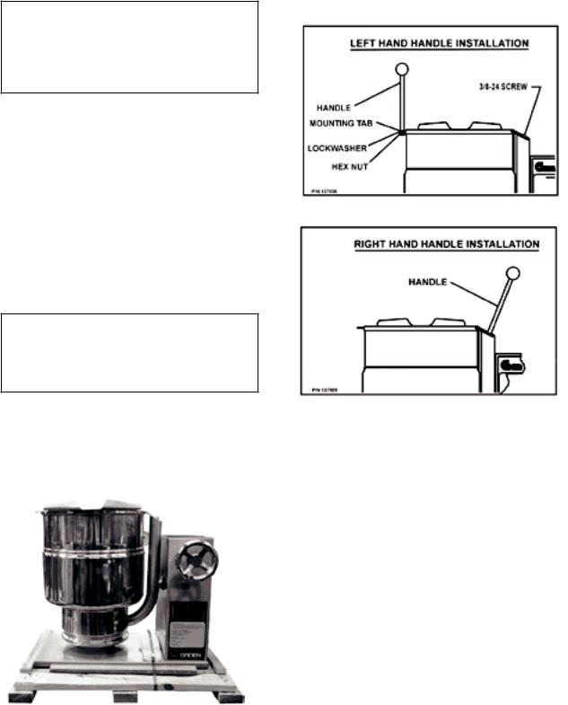
For TDB units, attach the tilt handle (normally shipped inside the kettle) by carefully threading it into the socket on the trunnion support. Be careful to avoid cross-threading the fine threads on the trunnion.
NOTE: After handle installation on the right hand side, retain the hardware supplied with the unit for left hand installation.
6

OM-TDB
Installation
The Groen Kettle is provided with complete internal wiring. It is ready for
immediate connection. A wiring diagram is provided in this
manual and on the inside of the control housing service panel. Any mechanical or electrical changes must be approved in by
Groen’s Food Service Engineering Department.
WARNING
INSTALLATION OF THE KETTLE MUST BE DONE BY A CERTIFIED ELECTRICIAN OR GROEN AUTHORIZED REPRESENTATIVE QUALIFIED TO WORK WITH ELECTRICITY. IMPROPER INSTALLATION CAN RESULT IN INJURY TO PERSONNEL AND/OR DAMAGE TO EQUIPMENT.
The completed unit has been operated at the factory to test all controls and heater elements.
1.Set the kettle in place and level it. The base should be securely fastened to a table or work surface. Four 3/8”-16 N.C. threaded couplings are provided in the base of unit. Installation under a ventilation hood is recommended.
2.Once the unit is anchored to a mounting surface, apply a small bead of silicone caulk around the perimeter of the kettle base and seal the joint.
3.Provide electrical power as specified on the electrical information plate attached to the equipment. Observe local codes and/or The National Electrical Code in accordance with ANSI/NFPA 70 - (current edition).
4.Standard equipment is shipped ready for 208V, 3-phase or 480V, 3-phase operation. Refer to the wiring diagram located on the inside cover of the control boxand the instructions below for conversion to single-phase operation. A jumper wire and “conversion” label are included with the unit. They can be found in a plastic bag attached to the trunnion assembly inside the control box.
CAUTION
BEFORE ANY ELECTRICAL CONVERSION, VERIFY THAT THE BRANCH CIRCUIT WIRING IS ADEQUATE TO HANDLE ANY INCREASE AMPERAGE REQUIREMENTS. REFER TO THE ELECTRICAL SPECIFICATIONS LISTED BELOW.
a.For conversion from 208V, 3-phase to 208V or 240V 1-phase OR 480V, 3-phase to 480V, 1-phase:
i.Verify that the branch circuit wiring is adequate for any increased amperage requirements (see table on page 8).
ii.For 240V 1-phase only, enlarge electrical inlet opening for 1" conduit fitting. Use a 1" sealtite conduit fitting.
iii.1-phase requires two jumper wires. One jumper wire exists on the terminal block for 3-phase input. The second jumper wire is located in a plastic bag inside the control box.
iv.Attach jumper wire to terminal block as per wiring diagram for 1-phase supply.
v.For 240V 1-phase only, pull lead from 208V tab on control transformer and insert on 240V tab (See Photo #1).
vi.Complete “conversion label” (supplied in bag) and adhere it to the control boxnear the UL dataplate.
b.For conversion from 208V, 3-phase to 240V, 3-phase:
i.Verify that the branch circuit wiring is adequate for any increased amperage requirements (see table on page 8).
ii.Pull lead from 208V tab on control transformer and insert on 240V tab. (See Photo #1)
iii.Complete “conversion label” (supplied in bag and adhere it to the control boxnear the UL dataplate).
7

OM-TDB
c.For conversion from 480V, 3-phase to
460V, 3-phase:
i.Verify that the branch circuit wiring is adequate for any increase amperage requirements (see table on page 8).
ii.Complete “conversion label” (supplied in bag and adhere it to the control boxnear the UL dataplate).
5.Bring incoming electrical service through the conduit fitting (for 240V 1-phase, a new one inch conduit fitting is required) at the rear of the support housing, making a watertight connection with the incoming lines. A BX style connection is not recommended.
DANGER ELECTRICALLY GROUND THE UNIT AT THE TERMINAL PROVIDED. FAILURE TO GROUND UNIT COULD RESULT IN ELECTROCUTION AND DEATH.
6.Confirm that the jacket water level is at or just above mid point of sight glass (new models). If the level is low, follow the instructions under “Jacket Filling and Water Treatment” in the “Maintenance” section of the manual.
7.Ensure that the open end of the elbow on the outlet of the pressure relief valve is directed downward.
TDB / TDBC SUPPLY WIRE REQUIREMENTS THWN (75°) / THHN (90°) COPPER ONLY
TDB-20, TDBC-20 |
TDB-40, TDBC-40 |
||||
VOLTAGE |
AMPS |
SUPPLY |
VOLTAGE |
AMPS |
SUPPLY |
|
|
WIRE |
|
|
WIRE |
208V 1 PH |
31 |
8 |
208V 1 PH |
52 |
6 |
3 PH |
18 |
12 |
3 PH |
30 |
8 |
240V 1 PH |
35 |
8 |
240V 1 PH |
60 |
4 |
3 PH |
20 |
12 |
3 PH |
35 |
8 |
460V 3 PH |
7.3 |
14 |
460V 3 PH |
14 |
12 |
480V 1 PH |
14 |
14 |
480V 1 PH |
25 |
10 |
3 PH |
8 |
14 |
3 PH |
15 |
12 |
Photo #1
Pull lead from 208V tab and insert on 240V tab.
8
 Loading...