


HY-3E
?
? IMPORTANT INFORMATION
IMPORTANT INFORMATION ???? KEEP FOR OPERATOR
? ?
IMPORTANT INFORMATION IMPORTANT INFORMATION
KEEP FOR OPERATOR ???? IMPORTANT INFORMATION
KEEP FOR OPERATOR KEEP FOR OPERATOR
OPERATOR MANUAL OM-HY-5E/HY-3E
Part Number 142412 DOMESTIC
MODELS: HY-3E,(2)HY-3E,
HY-5E, (2)HY-5E
HyPerSteam™
Atmospheric Convection
Steamer
Self-Contained
Electric Heated
Capacity: 5 Steamer Pans [per cavity] (HY-5E)
3 Steamer Pans [per cavity] (HY-3E)
(12" x 20" x 2½”)
(Re-Designed)
IMPORTANT INFORMATION ????
IMPORTANT INFORMATION IMPORTANT INFORMATION
THIS MANUAL MUST BE RETAINED FOR FUTURE REFERENCE. READ,
UNDERSTAND AND FOLLOW THE INSTRUCTIONS AND WARNINGS
CONTAINED IN THIS MANUAL.
FOR YOUR SAFETY
DO NOT STORE OR USE GASOLINE OR OTHER FLAMMABLE VAPORS AND
LIQUIDS IN THE VICINITY OF THIS OR ANY OTHER APPLIANCE
Information contained in this document is
known to be current and accurate at the time
of printing/creation. Unified Brands recommends referencing our product line websites,
unifiedbrands.net, for the most updated
product information and specifications.
.

IMP O RTANT — READ FIRST — IMPORTANT
WARNING: THE UNIT MUST BE INSTALLED BY PE RS ONNEL QUALIFIE D TO WORK WITH
ELECTRICITY AND PLUMBING. IMPROPER INSTALLATION CAN CAUSE INJURY TO
PERSONNEL AND/OR DAMAGE TO THE EQUIPMENT. THE UNIT MUST BE INSTALLED IN
ACCORDANCE WITH APPLICABLE CODE S .
CAUTION: SHIPPING S TRAPS ARE UNDER TENSION AND CAN SNAP BACK WHEN CUT.
CAUTION: DO NOT INSTALL THE UNIT IN ANY WAY WHICH WILL BLOCK THE S IDE VENTS, OR
WITHIN 12 INCHES O F A HEAT SOURCE SUCH AS A BRAISING PAN, DEEP FRYER, CHAR
BROILER OR KETTLE.
CAUTION: LEVEL THE UNIT FRONT T O BACK, OR PITCH IT SLIGHTLY TO THE REAR, TO AVOID
DRAINAGE PROBLEMS.
WARNING: FOLLOW THE WIRING DIAGRAM EXACTLY WHEN CONNECTING A UNIT TO AVOID
DAMAGE OR INJURY.
CAUTION: DO NOT US E P LASTIC PIPE. DRAIN MUST BE RATED FOR BOILING WATER.
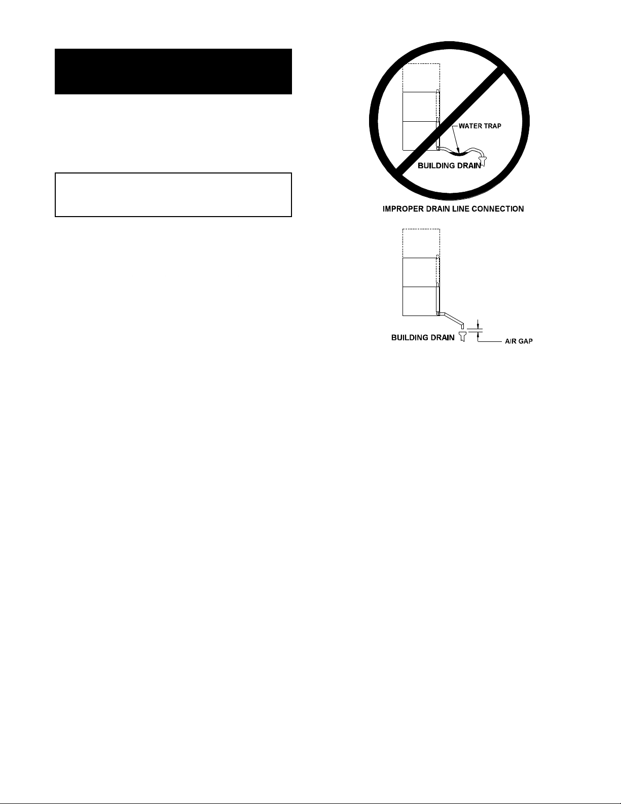
WARNING: DO NOT CONNECT T HE DRAIN DI RE CTLY T O A BUILDING DRAIN.
WARNING: BLOCKING THE DRAIN IS HAZARDOUS.
Important: Improper drain connection will void warranty.
Important: Do not allow any wat er t raps in the line. A trap can cause p ressure to build up inside the
cavity during steaming , which will make the door gasket l eak.
WARNING: WHEN YOU OPEN THE DOOR, STAY AWAY FROM STEAM COMING OUT OF THE UNIT .
STEAM CAN CAUSE BURNS.
WARNING: BEFORE CLEANING THE OUTSIDE OF THE STEAMER, DISCONNECT THE ELECTRIC
POWER SUPPLY. KEEP WATER AND CLEANING SOLUTIONS OUT OF CONTROLS AND
ELECTRICAL COMPONENTS. NEVER HOSE OR STEAM CLEAN ANY PART OF THE UNIT .
WARNING: ALLOW COOKING CHAMBER TO COOL BEFORE CLEANING.
WARNING: CAREFULLY READ THE WARNINGS AND FO LLOW THE DI RE CTIONS ON THE LABEL OF
EACH CLEANING AGENT.
RECOMMENDED BY DE LIMING AGENT MANUFACTURER.
WARNING: DO NOT M IX DE-LIMING AGENTS (ACID) AND DE-GREASERS (ALKALI) .
WARNING: DO NOT PUT HANDS OR TOOLS INTO THE COOKING CHAMBER UNTIL THE FAN HAS
STOPPED TURNING.
WARNING: DO NOT OPERATE T HE UNIT UNLESS THE REMOVABLE RIGHT SIDE PANEL HAS BEEN
RETURNED TO IT S P ROPER LOCATION.
NOTI CE : DO NOT US E A CLEANING OR DE-LIMING AGENT THAT CONTAINS ANY SULFAMIC ACID
OR ANY CHLORIDE, INCLUDING HYDROCHLORIC ACID. IF THE CHLORIDE CONTENT OF
ANY PRODUCT IS UNCLEAR, CONSULT THE MANUFACTURER.
NOTI CE : DO NOT US E ANY DE-GREASER THAT CONTAINS POTASSI UM HY DROXIDE OR SODI UM
HYDROXIDE O R THAT IS ALKALINE.
WARNING: USE OF ANY REPLACEMENT PARTS OTHER THAN THOSE SUPPLIED BY GROEN OR
THEIR AUTHORIZED DISTRIBUTOR VOIDS ALL WARRANTIES AND CAN RESULT IN
BODILY INJURY TO THE OPERATOR AND DAMAGE THE EQUIPMENT. SERVICE BY
OTHER THAN FACTORY-AUTHORIZED PERSONNEL WILL VOID ALL WARRANTIES.
USE SAFETY GLASSES AND RUBBER GLOVES AS
WARNING: HIGH VOL TAGE EXISTS INSIDE CONTROL COMP ARTMENTS. DISCONNECT F ROM
BRANCH CIRCUIT BEF ORE SERVICING. FAILURE TO DO SO CAN RESULT I N S E RIOUS
INJURY OR DEATH.
2

Table of Contents
OPERATOR WARNINGS................................................................. 2
REFERENCES ......................................................................... 3
EQUIPMENT DESCRIPTION .............................................................. 4
INSPECTION AND UNPACKING ........................................................... 4
WATER CONDITIONING ................................................................. 5
INSTALLATION AND START-UP ........................................................... 6
OPERATION........................................................................... 9
CLEANING ........................................................................... 11
MAINTENANCE ....................................................................... 13
TROUBLESHOOTING .................................................................. 13
PARTS LIST ........................................................................14-19
ELECTRICAL SCHEMATICS ...........................................................20-21
SERVICE LOG ........................................................................ 22
WARRANTY PROTECTION .............................................................. 23
References
UNDERW RITERS LABORAT ORIES, INC.
333 Pfi ngsten Road
Northbrook, Illinois 60062
NATIONAL FIRE PROTECTION ASSOCIATION
60 Batterymarch Park
Quincy, Massachusetts 02269
NFPA/70 The National Elec trical Code
NATIONAL S A NITATION F OUNDATION
3475 Plym outh Road
Ann Arbor, Michigan 48106
3
Equipment Description
Your Groen HY-5E or HY-3E HyPerSteam
Convection Steam er is designed to give years of
servi ce. It has a stainless steel c avity ( c ook ing
chamber) whic h is served by an independent
atmospheri c steam generator which i s el ec tricall y heated. A powerf ul blower circul ates the steam in
the cavity to increase heating effici enc y .
The cavity holds up to five (HY-5E) or thr ee ( HY - 3E )
steam table pans (12" x 20" x 2½ " deep) . An 18
gauge stainless steel case encl oses the cavity , the
steam generator and the control compartment that
houses electrical components. Door hinges are
rever sible (the door m ay be set to open from the left
or right) . Operating Contr ols are on the front panel.
HY-3E and HY-5E steamers are equipped with f ully
electronic controls and a butt on- ac tiv ated, preprogrammed CLEAN cycle. These units are readily
identified by their unique control panels. The OnOff switch is operated by t ouc h pad c ontrols, and
the disti nc tive symbol for st eam is integrat ed into
the panel. T he new models also have fewer panel
louvers on the right side.
The HY- 3E st eamer holds three
standard 12" x 20" x 2½ ” st eamer
pans.
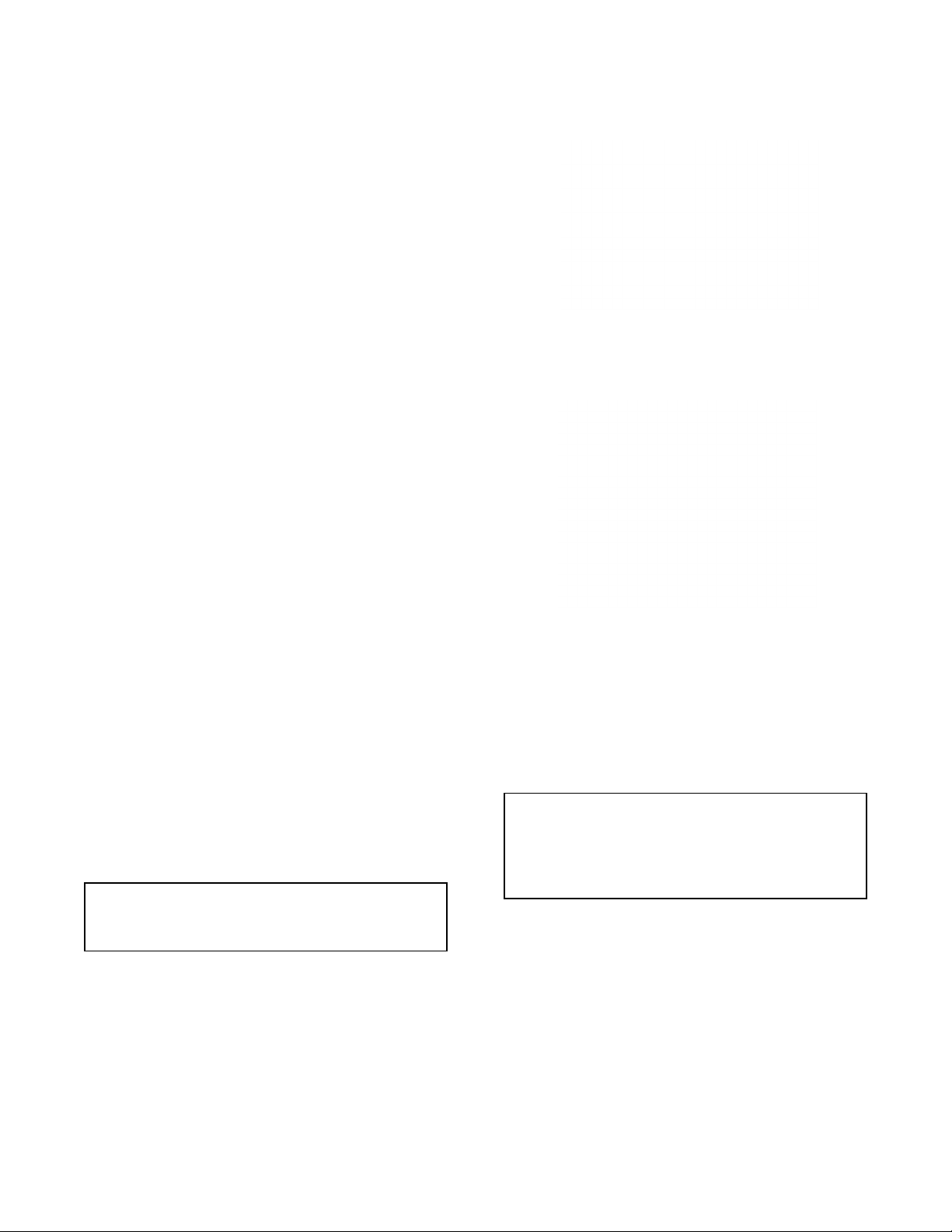
From t he rear HY-3E and HY-5E units are
distinguished by the addition of a fuse box, whi c h
lets operators change fuses without removing
panels.
The drain system on all models includes a spray
condenser, which helps keep steam from escaping
from the chamber and cools drain water.
Inspection and Unpacking
The Steamer will be delivered completely
assembled in a heavy shipping car ton strapped to a
skid. On receipt, inspect carton carefully for exterior
damage.
CAUTION
SHIPPING STRAPS ARE UNDER TENSION AND
CAN SNAP BACK WHEN CUT.
Caref ul ly cut the straps and detach the si des of the
car t o n f r om the ski d. P ull t he cart on up of f t he un i t .
Be careful to avoid personal injury or equipment
damage from staples which might be left in the carton
walls.
The HY-5E holds up to five pans.
CAUTION
THE HY-5E WEIGHS 230 POUNDS (104 KG).
THE THE HY-3E WEIGHS 180 POUNDS (82 KG).
YOU SHOULD GET HELP AS NEEDED TO LIFT
THIS WEIGHT SAFELY.
Wr ite down the model number, serial number and
installation date. Keep this information for reference.
Space for these entries is provided at the top of the
Serv ice Log in the back of this manual.
When starting instal lation, chec k pac k ing materi als
to make sure loose parts such as the condensate
drip tray ar e not discarded with thi s material.
4
Water Conditioning
It is essential to supply the steam generator with water
that will not form scale. Even though the steam
generator is engi neer ed to minimize scale formation,
scale dev elopment depends on the hardness of y our
water and the number of hours per day you operate
the equipm ent.
Most water supplies are full of minerals which form
scale. It is this scale which could lead to an early
component failure.
Your water utility can tell you about the minerals in
your water. The water going to the steam generator
should have more than 10 to 30 part s per million
(ppm) t otal dissolved solids (TDS) and should have a
pH (acidity rating) of 7.0 or higher. Please follow
these simpl e pr ec autions:
1. The best way to prevent scal e is to use a Groen
PureSteem™ Wat er Treatment S y stem which has
been specifically designed for Groen steamers
and combination ov ens. Do not rely on
unproven water treatment systems sold for
scale prevention and rem oval. They are not
specifically designed to work with Groen
steamers and combination ovens.
Models built sin ce 1998 have a fuse box
mounted on the rear.
On both the HY-3E and HY -5E, the dual water
connections are side by si de on the rear of the unit.
When seen from from the back of the unit, the
treated (softened) water intake is on the right.
2. A well-maint ained water treatm ent system and a
regular cartridge replacement schedule is
essential.
3. Using a Groen PureSteem™ Water Treatment
System will provide longer steam generator/boiler
life, higher steam capacity, and reduce
maint enanc e requirements.
4. If you notic e a sl owdown in steam production or
an increase in deliming, have the steamer
checked for scale build-up. This could be an
indicat ion that the water tr eatment cart r idges need
replacing. Heavy scal e r educ es the unit’s ability to
boil water, and c an even cause component failur e.
MINIMIZE SCALE PROBLEMS BY USING AND
MAINTAINING A SOFTENER AND BY CLEANING
(DELIMING) THE STEAMER REGULARLY.
The optional second water connection can
reduce treated water requirements.
5
Installation and Start-Up
WARNING
THE UNIT MUST BE INSTALLED BY PERSONNEL WHO ARE QUALIFIED TO WORK WITH ELECTRICITY
AND PLUMBING. IMPROPE R INSTALLATION CAN CAUSE INJURY T O PERSONNEL AND/OR DAMAGE
TO THE EQUIPME NT. THE UNIT MUST BE INSTALLE D IN ACCORDANCE WITH APPLICABLE CODES
CAUTION
DO NOT INSTALL THE UNIT WITH THE RIGHT OR LEFT SIDE VENTS BLOCKED OR WITHIN 12 INCHES
OF A HEAT SOURCE (SUCH AS A BRAISING PAN, DEEP FAT FRYER, CHARBROILER OR KETTLE).
TO AVOID DRAINAGE PROBLEMS, LEVEL THE UNIT FRONT TO BACK.
1. Electrical Supply Connection
.
A. Panel Removal
Open the wiri ng and c ontrol panel by removing
screws from the r ight side panel. S lide the
panel for ward, and set it aside.
B. Supply Vol tage
The unit must be operated at the rated
nameplat e volt age.
C. Phase Select ion
Refer to st eamer schemati c s (P ages 20-21) for
wiring information.
CAUTION
EACH UNIT MUST HAVE A SEPARATE
GROUND WIRE FOR SAFE OPERATIO N.
D. Terminal Bloc k
The terminal block for incoming power is
located at the back of the c ontrol compar tment.
The ground terminal is l oc ated in the wiring
compart ment near the terminal block.
E. Supply Wire
To determine the type of wire you need for the
power supply, find the operating voltage and
number of phases on the unit data plat e. Refer
to the tabl e below or to the label on the unit’s
back for correct wire size and t emperature
rating. The equipment gr ounding wire must
comply wi th the National E lectrical Code (NEC)
requirements. The schematic on the inside of
the unit’s right side cov er gives dir ec tions for
proper connection of the terminal bl ock jumpers.
The specified wire must be used, or the unit will
not meet Under writers Laboratories and NEC
requirements. The knockout hole is sized for a
¾ inch condui t fit ting on the HY-3E and for a
one inch conduit fit ting on the HY-5E.
WARNING
TO AVO ID DAMAGE OR PERSO NAL INJURY,
FOLLOW THE ELECTRICAL SCHEMATIC
EXACTLY WHEN CO NNE CTING THE UNIT..
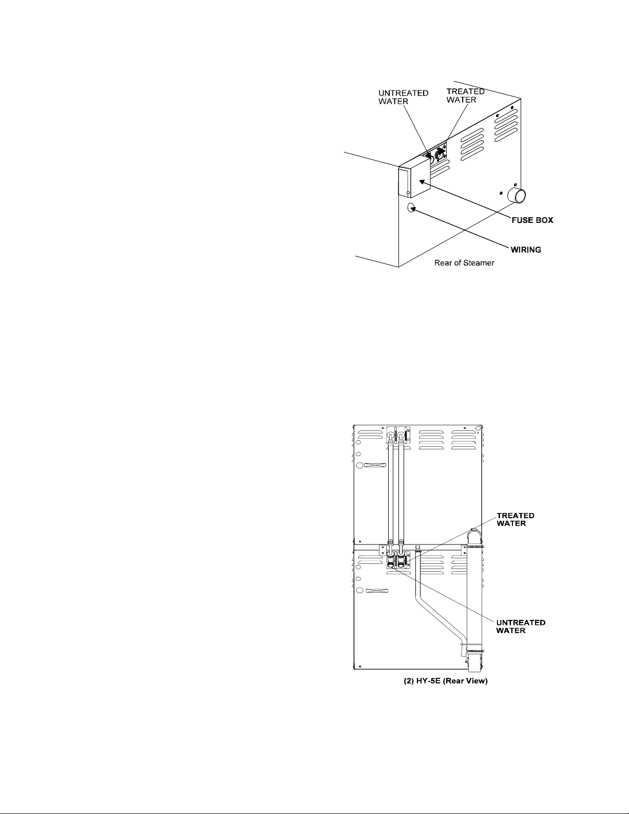
ELECTRICAL SUPPLY CONNECTIONS
FIELD WIRING TABLE - USE COPPER WIRE ONLY - INSULATION RATING THHN (90ºC)
VOLTAGE
(60 Hz Only)
480 3 PHASE 8.1 15.5 14 AWG 12 AW G 10 Amps 18.6 Amps
240 1 PHASE 8.1 15.5 8 AW G 4 AW G 33 A mps 64.6 Amps
240 3 PHASE 8.1 15.5 10 AWG 8 AWG 20 Amps 37.3 Am ps
208 1 PHASE 8.1 15.5 8 AW G 4 AW G 39 A mps 74.5 Amps
208 3 PHASE 8.1 15.5 10 AWG 6 AWG 23 Amps 43.0 Am ps
HY-3E HY-5E HY-3E HY-5E HY-3E HY-5E
KW FIELD WIRING RATED CURRENT DE M AND
6

Branch Circ uit Protection
Each Steamer, including individual units of
stacked models, should have its own branch
circuit protection and ground wire. Current
and power demands for each unit are as shown
on Page six.
IMPORTANT: Do not allow water traps in the
line. A trap can cause pressure bu ild-up i n the
cavity, which may cause the door gasket to leak.
4. Factory Stacked Units
2. Water Connection(s)
Install a c hec k valve to prevent back f low in the
incoming cold water line, as required by loc al
plumbing codes. Water pressure in the li ne
should be between 30 and 60 PSIG and must
deliver a flow rate of 1.5 to 3.0 gallons per
minut e. If pressure is above 60 PSIG, a
pressure regulator will be needed.
A ¾ inch female NH connec tor (garden hose
type) is used to attach the water supply to the
inlet valve. Minimum insi de diameter of the
water feed line is ½ inch. Use a washer in the
hose connection. Do not allow the connection to
leak, no matter how slowly. The dual water
standard connecti on, treated (soft ened) water
goes to the right ( seen from the rear of the unit ) ,
and untreated water to the left. Connections for
both are made as shown on Page Five.
3. Drain Connection
Level the steamer front to back, or pitch it
slightly to the rear (maximum ¼ inch) by
adjusting t he bullet f eet on the stand or cabinet
base.
A 2 inch [HY-5E] or 1½ inch [HY-3E] ID hose
may be att ached to the drain pi pe ( suppl ied).
WARNING:
DO NOT CONNECT T HE DRAIN DI RECT L Y T O
A BUILDING DRAIN. BLOCKING THE DRAIN IS
HAZARDOUS.
This section is applicable only if you are installing
factor y-stacked units. If you plan to stac k steamers
yourself , whether purchasing a new one for stacking
or a kit to stack two units you already own, you will
require O M-HY-3E(S), RET ROFIT SUPPLEMENT
(Part Number 121014). These instructions are also
valid for stac k ing HY-5E steamers.
Install ing stacked steamers is similar to installi ng a
single unit. The steamers are stack ed and
assembled at the factory and del ivered with the
water connections and drain hoses required for a
single point connection.
A. Water Connection
At the water inlet valve a ¾ inch female NH
connector (garden hose ty pe) is used for the
water supply. The dual water connection has
two connections to be made. Treated water
(softened) is connected to the ri ght val ve fitting
(looking from t he r ear of the unit) and untreated
water to the left fitting.
B. Electr ical Supply Connec tion
Separate, i ndividual electrical connections
will be required for each steamer in the
stack. Each St eamer must have its own
branch circuit protection.
C. Drain Connection
Steamers must be lev eled front t o back, or
pitched to the rear (maximum ¼ inch) by
adjusting t he bullet f eet on the cabinet or stand
base.
There must be a free air gap between the end of
the hose and the buil ding drain. The free air
gap should be as close as possible to the uni t
drain. T her e must also be no other elbows or
other restri c tions between the unit drain and the
free ai r gap.
CAUTION
DO NOT USE PLASTIC PIPE. DRA IN MUST BE
RATED FOR BO ILING WATER.
Install the drain line with a constant downward pitch.
For HY-3E a 1½ inch and for HY-5E a 2 inch ID
hose may be attac hed to the unit drai n. It must
be rated for boiling water.
7
WARNING
DO NOT CONNECT THE UNIT DRAIN DIRECTLY
TO THE BUILDING DRAIN.
Ensure that there is a free air gap bet ween the end
of the unit drain and the building drain. This gap
should be as close as possible to the uni t drain. Do
not allow el bows or restri c tions between the unit and
the free air gap.
CAUTION
DO NOT USE PLASTIC PIPE. DRA IN MUST BE
RATED FOR BO ILING WATER.
Install the line with a constant downward pit c h.
Rear view of (2) HY-5E — Note: Some drain parts
(elbow, clamps) for single mod els are packed inside
the steamer cavity
assembled. Installati on is the same fo r st acked HY-
5E and HY-3E units.
Rear view of (2) HY-5E — Note: Some drain parts
(elbow, clamps) for single mod els are packed inside
the steamer cavity
assembled. Installati on is the same fo r st acked HY5E and HY-3E units.
. Stacked un its are factory-
. Stacked un its are factory-
Proper Drain Line Connection — Drain Line
must have a constant downward pitch of at
least ¼” per f oot. (3)HY-3E shown. Connection
is 1½” for HY-3E, 2" for HY-5E.
8
 Loading...