


CC/0-E, C/2-20-E, (2)C/2-20E Service Manual")
IMPORTANTINFORMATION KEEPFOROPERATOR IMPORTANTINFORMATION
OPERATOR MANUAL |
OM-CC-E and C/2-E |
Part Number 121085 Rev. B |
DOMESTIC |
MODELS: CC10-E, (2)CC/0-E,
C/2-20-E, (2)C/2-20E
CONVECTION COMBO™
Combination Steamer-Oven
CC10-E
(2)C/2-20EFC
THIS MANUAL MUST BE RETAINED FOR FUTURE REFERENCE. READ, UNDERSTAND AND FOLLOW THE INSTRUCTIONS AND WARNINGS CONTAINED IN THIS MANUAL.
FOR YOUR SAFETY
DO NOT STORE OR USE GASOLINE OR OTHER FLAMMABLE VAPORS AND LIQUIDS IN THE VICINITY OF THIS OR ANY OTHER APPLIANCE.

OM-CC-E and C/2-E
|
IMPORTANT — READ FIRST — IMPORTANT |
|
WARNING: |
THE UNIT MUST BE INSTALLED BY PERSONNEL QUALIFIED TO WORK WITH ELECTRICITY |
|
|
AND PLUMBING. IMPROPER INSTALLATION CAN CAUSE INJURY TO PERSONNEL AND/OR |
|
|
DAMAGE TO THE EQUIPMENT. THE UNIT MUST BE INSTALLED IN ACCORDANCE WITH |
|
|
APPLICABLE CODES. |
|
CAUTION: |
SHIPPING STRAPS ARE UNDER TENSION AND CAN SNAP BACK WHEN CUT. |
|
CAUTION: |
DO NOT INSTALL THE UNIT IN ANY WAY WHICH WILL BLOCK THE RIGHT SIDE VENTS, OR |
|
|
WITHIN 12 INCHES OF A HEAT SOURCE SUCH AS A BRAISING PAN, DEEP FRYER, CHAR |
|
|
BROILER OR KETTLE. |
|
CAUTION: |
LEVEL THE UNIT FRONT TO BACK, OR PITCH IT SLIGHTLY TO THE REAR, TO AVOID |
|
|
DRAINAGE PROBLEMS. |
|
WARNING: |
TO AVOID DAMAGE OR INJURY, FOLLOW THE WIRING DIAGRAM EXACTLY WHEN |
|
|
CONNECTING A UNIT. |
|
CAUTION: |
DO NOT USE PLASTIC PIPE. DRAIN MUST BE RATED FOR BOILING WATER. |
|
WARNING: |
DO NOT CONNECT THE DRAIN DIRECTLY TO A BUILDING DRAIN. |
|
WARNING: |
BLOCKING THE DRAIN IS HAZARDOUS. |
|
IMPORTANT: IMPROPER DRAIN CONNECTION WILL VOID WARRANTY. |
||
IMPORTANT: DO NOT ALLOW ANY WATER TRAPS IN THE LINE. A TRAP CAN CAUSE PRESSURE TO |
||
|
BUILD UP INSIDE THE CAVITY DURING STEAMING, WHICH WILL MAKE THE DOOR GASKET |
|
WARNING: |
LEAK. |
|
WHEN YOU OPEN THE DOOR, STAY AWAY FROM STEAM COMING OUT OF THE UNIT. |
||
|
STEAM CAN CAUSE BURNS. |
|
WARNING: |
BEFORE CLEANING THE OUTSIDE OF THE OVEN, DISCONNECT THE ELECTRIC POWER |
|
|
SUPPLY. KEEP WATER AND CLEANING SOLUTIONS OUT OF CONTROLS AND |
|
|
ELECTRICAL COMPONENTS. NEVER HOSE OR STEAM CLEAN ANY PART OF THE UNIT. |
|
WARNING: |
ALLOW COOKING CHAMBER TO COOL BEFORE CLEANING. |
|
WARNING: |
CAREFULLY READ THE WARNINGS AND FOLLOW THE DIRECTIONS ON THE LABEL OF |
|
|
EACH CLEANING AGENT. USE SAFETY GLASSES AND RUBBER GLOVES AS |
|
|
RECOMMENDED BY DELIMING AGENT MANUFACTURER. |
|
WARNING: |
DO NOT MIX DE-LIMING AGENTS (ACID) AND DE-GREASERS (ALKALI). |
|
WARNING: |
DO NOT PUT HANDS OR TOOLS INTO THE COOKING CHAMBER UNTIL THE FAN HAS |
|
|
STOPPED TURNING. |
|
WARNING: |
DO NOT OPERATE THE UNIT UNLESS THE REMOVABLE RIGHT SIDE PANEL HAS BEEN |
|
|
RETURNED TO ITS PROPER LOCATION. |
|
NOTICE: |
DO NOT USE A CLEANING OR DE-LIMING AGENT THAT CONTAINS ANY SULFAMIC ACID |
|
|
OR ANY CHLORIDE, INCLUDING HYDROCHLORIC ACID. IF THE CHLORIDE CONTENT OF |
|
|
ANY PRODUCT IS UNCLEAR, CONSULT THE MANUFACTURER. |
|
NOTICE: |
DO NOT USE ANY DE-GREASER THAT CONTAINS POTASSIUM HYDROXIDE OR SODIUM |
|
|
HYDROXIDE OR THAT IS ALKALINE. |
|
WARNING: |
USE OF ANY REPLACEMENT PARTS OTHER THAN THOSE SUPPLIED BY GROEN OR THEIR |
|
|
AUTHORIZED DISTRIBUTOR VOIDS ALL WARRANTIES AND CAN RESULT IN BODILY |
|
|
INJURY TO THE OPERATOR AND DAMAGE THE EQUIPMENT. SERVICE BY OTHER THAN |
|
|
FACTORY-AUTHORIZED PERSONNEL WILL VOID ALL WARRANTIES. |
|
WARNING: |
HIGH VOLTAGE EXISTS INSIDE CONTROL COMPARTMENTS. DISCONNECT FROM BRANCH |
|
|
BEFORE SERVICING. FAILURE TO DO SO CAN RESULT IN SERIOUS INJURY OR DEATH. |
|
2
OM-CC-E and C/2-E
Table of Contents
OPERATOR WARNINGS . . . . . . . . . . . . . . . . . . . . . . . . . . . . . . . . . . . . . . . . . . . . . . . . . . . . . . 2 REFERENCES . . . . . . . . . . . . . . . . . . . . . . . . . . . . . . . . . . . . . . . . . . . . . . . . . . . . . . . . . . . . . . 3
EQUIPMENT DESCRIPTION . . . . . . . . . . . . . . . . . . . . . . . . . . . . . . . . . . . . . . . . . . . . . . . . . . . 4
INSPECTION AND UNPACKING . . . . . . . . . . . . . . . . . . . . . . . . . . . . . . . . . . . . . . . . . . . . . . . . 5
WATER QUALITY AND TREATMENT . . . . . . . . . . . . . . . . . . . . . . . . . . . . . . . . . . . . . . . . . . . . 5
INSTALLATION AND START-UP INSTRUCTIONS . . . . . . . . . . . . . . . . . . . . . . . . . . . . . . . . . . 7 OPERATING INSTRUCTIONS . . . . . . . . . . . . . . . . . . . . . . . . . . . . . . . . . . . . . . . . . . . . . . . . . 13
CLEANING . . . . . . . . . . . . . . . . . . . . . . . . . . . . . . . . . . . . . . . . . . . . . . . . . . . . . . . . . . . . . . . . 19
MAINTENANCE . . . . . . . . . . . . . . . . . . . . . . . . . . . . . . . . . . . . . . . . . . . . . . . . . . . . . . . . . . . 21
TROUBLESHOOTING . . . . . . . . . . . . . . . . . . . . . . . . . . . . . . . . . . . . . . . . . . . . . . . . . . . . . . . 21 DIAGRAMS AND SCHEMATICS . . . . . . . . . . . . . . . . . . . . . . . . . . . . . . . . . . . . . . . . . . . . . . . 23 SERVICE LOG . . . . . . . . . . . . . . . . . . . . . . . . . . . . . . . . . . . . . . . . . . . . . . . . . . . . . . . . . . . . . 27
References
UNDERWRITERS LABORATORIES, INC. |
NATIONAL FIRE PROTECTION |
333 Pfingsten Road |
ASSOCIATION |
Northbrook, Illinois 60062 |
60 Battery March Park |
|
Quincy, Massachusetts 02269 |
KLENZADE SALES CENTER |
NFPA/70 The National Electrical Code |
ECOLAB, Inc. |
NATIONAL SANITATION FOUNDATION |
370 Wabasha |
|
St. Paul, Minnesota 55102 |
3475 Plymouth Road |
800 328-3663 or 612 293-2233 |
Ann Arbor, Michigan 48106 |
3
OM-CC-E and C/2-E
Equipment Description
Your Groen Convection Combo™ has a stainless steel cooking chamber, an air heating compartment with electric heating elements and fan, a steam generator with electric heating elements, and a control compartment which houses other electrical components.
All major components of the Convection Combo™ are encased in a 16 gauge stainless steel cabinet. Glass fiber insulation, lines the cabinet at a thickness of 1½ to 2 inches (4 to 5 cm). A removable drip tray is located beneath the door.
The door is reversible so that it may open from the left or right side. Operator controls are located on the right side of the front panel.
Standard controls let you to operate the Convection Combo in any one of three cooking modes:
3.As a convection oven
4.As a self-contained, pressureless steamer
5.As a combination oven-steamer
CC10-E and C/2-20E models differ in cooking chamber size and capacity:
CC10-E: 4 steam table pans (12x20x2½”), or 7 half-size (13x18") US bake pans
C/2-20E: 10 steam table pans (12x20x2½”), or 9 full-size (18x26") US bake pans
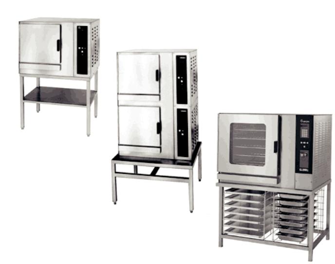
The smaller Convection Combo™ is available as a table-top unit (the single CC10-E). These units are also supplied on a stainless steel stand as models CC10-EF and (2)CC10-EF. The larger Convection Combo™ is always supplied with a stand as the single C/2-20EF or the double-stacked (2)C/2-20EF.
CC-10EF
(2)CC10-EF
C/2-20EFC with optional pan rack
4
OM-CC-E and C/2-E
Inspection and Unpacking
Your Convection Combo™ will be completely assembled in a heavy shipping carton or wooden crate, and attached to a skid. On receipt, inspect the carton or crate carefully for exterior damage.
CAUTION
SHIPPING STRAPS ARE UNDER TENSION AND CAN SNAP BACK WHEN CUT.
Carefully cut the straps around the carton and detach the sides of the carton from the skid. Pull the carton up off the unit. Be careful to avoid personal injury or equipment damage from staples which might be left in the carton walls.
Write down the model number, serial number and installation date and keep this information for future reference. Space for theseentries isprovidedatthetop of the Service Log in the back of this manual.
CAUTION
THIS UNIT IS VERY HEAVY. YOU SHOULD GET HELP AS NEEDED TO LIFT THIS WEIGHT SAFELY.
When starting installation, lift the unit straight up off the skid. Check packing materials to make sure loose parts are not discarded with the material.
Water Quality and Treatment
It is essential to supply the steam generator/boiler with water that will not form scale. Even though the steam generator/boiler is engineered to minimize scale formation, scale development depends on the hardness of your water and the number of hours you operate the equipment each day.
But most water supplies contain minerals which form scale. It is this scale which could lead to an early component failure.
Your local water utility can tell you about the minerals in your water. The water going to the steam generator should have between 30 and 40 parts per million (ppm) total dissolved solids (TDS) and should have a pH (acidity rating) of 7.0 to 9.0. Please follow these simple precautions:
1.The best way to prevent scale is to use a Groen Puresteam™ Water Treatment System which has been specifically designed for Groen steamers and combination ovens. Do not rely on unproven water treatments systems sold for scale prevention and removal. They are not specifically designed to work with Groen steamers and combination ovens.
2.A well-maintained water treatment system and a regular cartridge replacement schedule is essential.
3.Using a Groen Water Treatment System will provide longer steam generator/boiler life, higher steam capacity, and reduce maintenance requirements.
4.If you notice a slowdown in steam production or an increase in deliming, have the combo checked for scale build-up. This could be an indication that the water treatment cartridges need replacing. Heavy scale reduces the unit’s ability
to boil water, and can even cause component failure.
MINIMIZE SCALE PROBLEMS BY INSTALLING AND MAINTAINING A GROEN PURESTEAM™ WATER TREATMENT SYSTEM AND BY DELIMING THE STEAM GENERATOR/BOILER REGULARLY.
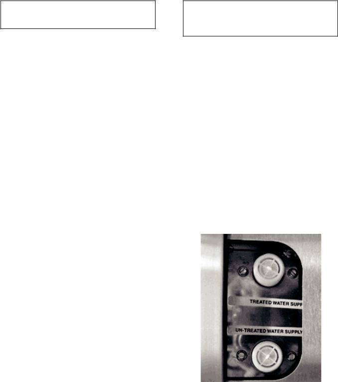
Groen Convection Combo™ ovens feature two separate water inlets — one for the steam generator/boiler (for treated water), the other for the spray condenser (untreated water). The second intake will reduce treatment requirements resulting in significant savings.
The dual water connections are on the rear of the unit.
Standard water connections for steam generator and drain spray condenser.
5
OM-CC-E and C/2-E
Installation and Start-Up
WARNING
THE UNIT MUST BE INSTALLED BY PERSONNEL WHO ARE QUALIFIED TO WORK WITH ELECTRICITY ANDPLUMBING. IMPROPERINSTALLATIONCAN CAUSE INJURY TO PERSONNELAND/ORDAMAGETO THE EQUIPMENT. THE UNIT MUST BE INSTALLED IN ACCORDANCE WITH APPLICABLE CODES.
CAUTION
DO NOT INSTALL THE UNIT WITH THE RIGHT SIDE VENTS BLOCKED OR WITHIN 12 INCHES OF A HEAT SOURCE (SUCH AS ABRAISING PAN, DEEP FRYER, CHAR BROILER OR KETTLE). DO NOT INSTALL TO THE LEFT OF ANY OPEN-FLAME EQUIPMENT.
DO NOT INSTALL WITHIN FOUR FEET OF A STEAM DRAIN.
TO AVOID DRAINAGE PROBLEMS, LEVEL THE UNIT FRONT TO BACK. INSTALLATION MUST BE IN ACCORDANCE WITH ALL APPLICABLE CODES.
1. Mounting
Minimum rear clearance is 6" from back wall.
If you wish to install a Convection Combo™ on top of another, you should obtain a double stacked unit from the factory.
If the unit does not have a factory-installed stand, the installer must provide a table, stand or counter which is strong enough to support the unit. Use of casters is not recommended.
To avoid drainage problems, level the unit front to rear, or provide a slight pitch to the rear.
Bolt the unit to the table, stand or counter top, using the mounting holes in its base.
2.Electrical Supply Connections
b.Panel Removal
The right side panel must be removed to gain access to the wiring and control compartment. Remove the two screws at the bottom of the panel. Slide the panel toward the front of the unit, lift it and set it aside.
c.Supply Voltage
CC10-E and C/2-20E models must operate at the rated nameplate voltage, plus or minus 10%.
d.Terminal block
The terminal block for incoming power is located at the back of the control compartment.
WARNING
WHEN CONNECTING FOR SINGLE PHASE OPERATION, DO NOT CONNECT ANY WIRE TO LINE3(THETERMINALFARTHEST LEFT). THIS WILL CAUSE A SHORT CIRCUIT.
6

FOR CC10-E Models:
The ground terminal is found on the relay bracket below the terminal block. The Convection Combo™ must have a separate ground wire for safe operation. The ground wire must be at least 10 AWG (2.6 mm).
FOR C/2-20E Models:
The ground terminal is found below the terminal block. The Convection Combo™ must have a separate ground wire for safe operation. The ground wire must be at least 8 AWG (3.3 mm) for a 100 amp circuit breaker or 10 AWG (2.6 mm) for a 40 to 60 amp breaker.
e.Supply Wire
The type of wire needed is determined by finding the operating voltage and phase from the unit’s back data plate and (on pre-1996 models) phase select connector. Refer to the “Electrical Supply Connection” label on the back of the unit for correct wire size and insulation temperature rating.
The specified wire must be used to comply with Underwriters Laboratories and National Electric Code requirements.
The knockout hole is sized for a ¾ inch (19 mm) conduit fitting in CC10-E models, and one inch (25.4 mm) for C/2-20E models.
ELECTRICAL SUPPLY CONNECTION
(All wires copper only. Reference: National Electrical Code)
CC10-E MODELS
Voltage |
Phase |
Wire Size |
Insulation |
208 |
1 |
6AWG (4.1mm) |
75oC |
208 |
1 |
8AWG (3.3mm) |
90oC |
208 |
3 |
8AWG (3.3mm) |
75oC |
240 |
1 |
8AWG (3.3mm) |
75oC |
240 |
3 |
8AWG (3.3mm) |
75oC |
C/2-20E MODELS
Voltage |
Size fo 75°C |
Size for 90°C |
|
(THWN) |
(TWHN) |
||
|
|||
208 |
4 AWG (5.2 mm) |
6 AWG (4.1 mm) |
|
240 |
4 AWG (5.2 mm) |
6 AWG (4.1 mm) |
|
480 |
8 AWG (3.3 mm) |
8 AWG (3.3 mm) |
f.Branch Circuit Protection
Groen strongly recommends that each Convection Combo™ have its own branch circuit protection. A double -stacked unit
OM-CC-E and C/2-E
should have separate protection for the upper and lower steamer-ovens.
CURRENT DEMAND
CC10-E MODELS
Voltage |
|
Current |
|
Power |
|
|
1 Phase |
|
3 Ph., per Line |
|
|
||
208 |
44.7 A |
|
27.5 A |
|
9.3 KW |
|
|
|
|
|
|
|
|
240 |
38.8 A |
|
24.1 A |
|
9.3 KW |
|
|
|
|
|
|
||
|
C/2-20E MODELS |
|
|
|
||
|
|
|
|
|
||
Voltage |
Current per line |
|
Power |
|
||
(Three Phase) |
|
|
||||
|
|
|
|
|||
208 |
|
|
65.4 A |
|
21 KW |
|
240 |
|
|
56.7 A |
|
21 KW |
|
480 |
|
|
28.3 A |
|
21 KW |
|
Each current-carrying conductor must have overcurrent protection. Refer to the label on the back of the unit for proper wire size and type. Watertight connections are required.
3. Water Supply Connection
A check valve (back siphonage device) must be installed in the incoming cold water lines in keeping with local plumbing codes. Water line pressure should be between 30 and 60 PSI (210 and 410 kPa). A pressure regulator is required above 60 PSI (410 kPa).
A ¾ inch (19 mm) NH (garden hose type) connector is required to connect the water supply to the water inlet valve. The water feed line diameter may not be less than ½ inch (13 mm). Use a washer (or if necessary, two washers) in the hose connection. Do not allow the connection to have any leak, no matter how small.
The CC10-E and C/2-20E are equipped with a dual water supply. Treated water must be supplied at a minimum rate of 1.5 gallons per minute. Untreated water must be supplied at a minimum rate of .34 gallons per minute for the CC10-E and .75 gallons per minute for the C/2-20E. Minimum water pressure for both the CC10-E and C/2-20E is 30 PSI. Double-stack units require doubled rates. To convert a steamer or combination oven to a single water connection, order single cold water adapter (part # 138473).
4.Drain Connection
a.CC10-E and C/2-20E Without Drain Tank (tabletop model)
A 1.5" hose for 10-E models or a 2" hose for 20-E models may be attached to the provided
7
OM-CC-E and C/2-E
drain elbow with a clamp. Do not use plastic pipe. The drain must withstand boiling water.
WARNING:
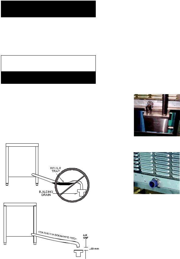
DONOT CONNECT THE DRAIN DIRECTLY TO A BUILDING DRAIN.
There must be a free air gap between the end of the hose and the building drain. The free air gap should be as close as possible to the unit’s drain. There must also be no other elbows or other restrictions between the unit drain and the two inch free air gap.
CAUTION
DO NOT USE PLASTIC PIPE. DRAIN MUST BE RATED FOR BOILING WATER.
WARNING BLOCKING THE DRAIN IS HAZARDOUS.
Install the drain line with a constant downward pitch. This is especially important for double-stack units. The bottom unit is conceptually shown below.
IMPORTANT: Do not allow any water traps in the line. A trap can cause pressure to build up inside the cavity during steaming, which will make the door gasket leak.
NOTE: Improper drain connection will void the warranty.
b.CC10-E and C/2-20E With Drain Tank
CC10-E Models:
A 1½ inch (4 cm) ID hose may be attached to the supplied drain elbow with a clamp.
C/2-20E Models:
A two inch (51 cm) ID hose may be attached to the supplied drain elbow with a clamp.
The hose may be connected directly to a building drain since the drain tank has an air vent, which eliminates the need for a free air gap at the building drain. Do not block the air vent in any way. Do not attach anything to the vent tube or reduce its size.
Do NOT use plastic pipe in the drain line, because the drain must withstand boiling water.
Drain Tank
Tabletop Model
2 in (50mm)
8
 Loading...