


 IMPORTANT INFORMATION
 KEEP FOR OPERATO
  IMPORTANT INFORMATION
OPERATOR MANUAL |
OM-CC-G |
Part Number 121020 - Rev. A |
DOMESTIC |
MODEL: CC10-GF, (2)CC10-GF
CC20-GF, (2)CC20-GF
CONVECTION COMBO™
Combination Steamer-
Oven
THIS MANUAL MUST BE RETAINED FOR FUTURE REFERENCE. READ, UNDERSTAND AND FOLLOW THE INSTRUCTIONS AND WARNINGS CONTAINED IN THIS MANUAL.
FOR YOUR SAFETY
DO NOT STORE OR USE GASOLINE OR OTHER FLAMMABLE VAPORS AND LIQUIDS IN THE VICINITY OF THIS OR ANY OTHER APPLIANCE.
POST IN A PROMINENT LOCATION
INSTRUCTIONS TO BE FOLLOWED IN THE EVENT USER SMELLS GAS. THIS INFORMATION SHALL BE OBTAINED BY CONSULTING YOUR LOCAL GAS SUPPLIER. AS A MINIMUM, TURN OFF THE GAS AND CALL YOUR GAS COMPANY AND YOUR AUTHORIZED SERVICE AGENT. EVACUATE ALL PERSONNEL FROM THE AREA.
WARNING: IMPROPER INSTALLATION, ADJUSTMENT, ALTERATION, SERVICE OR MAINTENANCE CAN CAUSE PROPERTY DAMAGE, INJURY OR DEATH. READ THE INSTALLATION, OPERATING AND MAINTENANCE INSTRUCTIONS THOROUGHLY BEFORE INSTALLING OR SERVICING THIS EQUIPMENT.
Information contained in this document is known to be current and accurate at the time of printing/creation. Unified Brands recommends referencing our product line websites, unifiedbrands.net, for the most updated product information and specifications.

OM-CC-G
IMPORTANT — READ FIRST — IMPORTANT
WARNING: THE UNIT MUST BE INSTALLED BY PERSONNEL QUALIFIED TO WORK WITH ELECTRICITY AND PLUMBING. IMPROPER INSTALLATION CAN CAUSE INJURY TO PERSONNEL AND/OR DAMAGE TO THE EQUIPMENT. THE UNIT MUST BE INSTALLED IN ACCORDANCE WITH APPLICABLE CODES.
CAUTION: |
SHIPPING STRAPS ARE UNDER TENSION AND CAN SNAP BACK WHEN CUT. |
CAUTION: |
DO NOT INSTALL THE UNIT IN ANY WAY WHICH WILL BLOCK THE RIGHT SIDE VENTS, |
|
OR WITHIN 12 INCHES OF A HEAT SOURCE SUCH AS A BRAISING PAN, FRYER, CHAR |
|
BROILER OR KETTLE. |
CAUTION: |
LEVEL THE UNIT FRONT TO BACK, OR PITCH IT SLIGHTLY TO THE REAR, TO AVOID |
|
DRAINAGE PROBLEMS. |
WARNING: TO AVOID DAMAGE OR INJURY, FOLLOW THE WIRING DIAGRAM EXACTLY WHEN CONNECTING A UNIT.
CAUTION: |
DO NOT USE PLASTIC PIPE. DRAIN MUST BE RATED FOR BOILING WATER. |
WARNING: DO NOT CONNECT THE DRAIN DIRECTLY TO A BUILDING DRAIN.
WARNING: BLOCKING THE DRAIN IS HAZARDOUS.
IMPORTANT: Improper drain connection will void warranty.
IMPORTANT: Do not allow any water traps in the line. A trap can cause pressure to build up inside the cavity during steaming, which will make the door gasket leak.
WARNING: WHEN YOU OPEN THE DOOR, STAY AWAY FROM STEAM COMING OUT OF THE UNIT. STEAM CAN CAUSE BURNS.
WARNING: BEFORE CLEANING THE OUTSIDE OF THE STEAMER, DISCONNECT THE ELECTRIC POWER SUPPLY. KEEP WATER AND CLEANING SOLUTIONS OUT OF CONTROLS AND ELECTRICAL COMPONENTS. NEVER HOSE OR STEAM CLEAN ANY PART OF THE UNIT.
WARNING: ALLOW COOKING CHAMBER TO COOL BEFORE CLEANING.
WARNING: CAREFULLY READ THE WARNINGS AND FOLLOW THE DIRECTIONS ON THE LABEL OF EACH CLEANING AGENT. USE SAFETY GLASSES AND RUBBER GLOVES AS RECOMMENDED BY DELIMING AGENT MANUFACTURER.
WARNING: DO NOT MIX DE-LIMING AGENTS (ACID) AND DE-GREASERS (ALKALI).
WARNING: DO NOT PUT HANDS OR TOOLS INTO THE COOKING CHAMBER UNTIL THE FAN HAS STOPPED TURNING.
WARNING: |
DO NOT OPERATE THE UNIT UNLESS THE REMOVABLE RIGHT SIDE PANEL HAS BEEN |
|
RETURNED TO ITS PROPER LOCATION. |
NOTICE: |
DO NOT USE A CLEANING OR DE-LIMING AGENT THAT CONTAINS ANY SULFAMIC ACID |
|
OR ANY CHLORIDE, INCLUDING HYDROCHLORIC ACID. IF THE CHLORIDE CONTENT OF |
|
ANY PRODUCT IS UNCLEAR, CONSULT THE DISTRIBUTOR OR MANUFACTURER. |
NOTICE: |
DO NOT USE ANY DE-GREASER THAT CONTAINS POTASSIUM HYDROXIDE OR SODIUM |
|
HYDROXIDE OR THAT IS ALKALINE. |
WARNING: USE OF ANY REPLACEMENT PARTS OTHER THAN THOSE SUPPLIED BY GROEN OR THEIR AUTHORIZED DISTRIBUTOR VOIDS ALL WARRANTIES AND CAN RESULT IN BODILY INJURY TO THE OPERATOR AND DAMAGE THE EQUIPMENT. SERVICE BY OTHER THAN FACTORYAUTHORIZED PERSONNEL WILL VOID ALL WARRANTIES.
WARNING: HIGH VOLTAGE EXISTS INSIDE CONTROL COMPARTMENTS. DISCONNECT FROM BRANCH BEFORE SERVICING. FAILURE TO DO SO CAN RESULT IN SERIOUS INJURY OR DEATH.
2
|
OM-CC-G |
Table of Contents |
|
IMPORTANT OPERATOR SAFETY WARNINGS . . . . . . . . . . . . . . . . . . . . . . . . . |
. . . . . . . . 2 |
EQUIPMENT DESCRIPTION . . . . . . . . . . . . . . . . . . . . . . . . . . . . . . . . . . . . . . . . |
. . . . . . . . 4 |
INSPECTION AND UNPACKING . . . . . . . . . . . . . . . . . . . . . . . . . . . . . . . . . . . . . . |
. . . . . . . 5 |
WATER CONDITIONING/REQUIREMENTS . . . . . . . . . . . . . . . . . . . . . . . . . . . . . . |
. . . . . . . 6 |
INSTALLATION . . . . . . . . . . . . . . . . . . . . . . . . . . . . . . . . . . . . . . . . . . . . . . . . . . . |
. . . . . . 7 |
INITIAL START-UP . . . . . . . . . . . . . . . . . . . . . . . . . . . . . . . . . . . . . . . . . . . . . . . . . |
. . . . . . 11 |
OPERATING INSTRUCTIONS . . . . . . . . . . . . . . . . . . . . . . . . . . . . . . . . . . . . . . . . |
. . . . . . 13 |
CLEANING . . . . . . . . . . . . . . . . . . . . . . . . . . . . . . . . . . . . . . . . . . . . . . . . . . . . . . |
. . . . . . 19 |
MAINTENANCE . . . . . . . . . . . . . . . . . . . . . . . . . . . . . . . . . . . . . . . . . . . . . . . . . . |
. . . . . . 26 |
TROUBLESHOOTING . . . . . . . . . . . . . . . . . . . . . . . . . . . . . . . . . . . . . . . . . . . . . . |
. . . . . . 26 |
DIAGRAMS AND SCHEMATICS . . . . . . . . . . . . . . . . . . . . . . . . . . . . . . . . . . . . . . . |
. . . . . . 28 |
REFERENCE . . . . . . . . . . . . . . . . . . . . . . . . . . . . . . . . . . . . . . . . . . . . . . . . . . . . . |
. . . . . . 29 |
SERVICE LOG . . . . . . . . . . . . . . . . . . . . . . . . . . . . . . . . . . . . . . . . . . . . . . . . . . . . |
. . . . . . 30 |
WARRANTY PROTECTION . . . . . . . . . . . . . . . . . . . . . . . . . . . . . . . . . . . . . . . . . . |
. . . . . . 31 |
3

OM-CC-G
Equipment Description
Your Groen Convection Combo™ has a stainless steel cooking chamber, an air heating compartment with heat exchange tubes and fan, a steam generator, and a control compartment which houses electrical components.
All major components of the Convection Combo™ are encased in a 16 gauge stainless steel cabinet. The cabinet is lined with 1½ to 2 inches (4 to 5 cm) thick glass fiber insulation. A removable drip tray is located beneath the door.
Door hinges are reversible so that doors may open from the left or right. Operator controls are located on the right front of the unit, except for the pilot control switch and manual gas shut-off valve, which are behind the sliding access door on the right side.
Standard controls let you to operate the Convection Combo in any one of three cooking modes:
1.As a convection oven
2.As a self-contained pressureless steamer
3.As a combination oven-steamer
Models CC10-G and CC20-G differ in cooking chamber size and pan capacity:
CC10-G: 4 steam table pans (12x20x2½”), or 7 half-size (13x18") US baking pans
CC20-G: 10 steam table pans (12x20x2½”), or 9 full-size (18x26") US baking pans
Although some early model CC10-G units were manufactured for counter-top installation, all units are now supplied on a stainless steel stand. The smaller Convection Combo™ is available as the single CC10GF or the double stacked (2) CC10-GF. The larger unit is available as the single CC20-GF or the doublestacked (2)CC20-GF.
Controls and monitoring displays for cooking times, operating mode and temperature selection are on the control panel. The upper portion of the panel has a digital cooking time readout and touch pads for setting cook times. Below the timer section are lights which indicate the status of the unit and touch pads to select the mode of operation and to switch on power.
A digital readout shows the selected temperature, which is entered by turning a dial. Pilot burner status is shown by a light on the pilot ignition switch.
An insulated, gas-fired steam generator is mounted behind the oven. Steam enters the oven through a connecting tube near the bottom left rear corner of the oven.
On single CC10-G units which were supplied without stands, de-liming solution is added to the unit through the port located on top of the unit, directly above the steam generator. Units supplied with stands have a port on the stand just below the control panel. Deliming solution goes through this port into a fill tank, from which it is transferred to the steam generator during the unique Groen automatic cleaning cycle.
The air heating space which contains the heat exchanger tubes is also separated from the cooking chamber by removable left, right, top and bottom partitions. The compartment which contains the unit’s automatic controls and other electrical components is on the right side of the unit, and is accessed by removing the right outside panel.
A drain is located in the removable bottom of the cooking chamber. Fluids drain from this removable bottom and from the permanent floor to the stainless steel drain pipe outside the oven. The drain pipe includes a spray condensor, which suppresses any steam escaping from the chamber. On Convection Combo™ units manufactured after August 1, 1991, the drain assembly also includes a drain box.
BURNER FIRING RATES
Input Rates, BTU/hour
CC10-G or per chamber for (2)CC10-G
Mode |
Natural Gas |
L.P. Gas |
|
at 3.7" W.C.* |
at 10.5" W.C.* |
||
|
|||
Oven |
45,000 |
45,000 |
|
Steam |
48,000 |
48,000 |
|
Combo |
54,600 |
54,600 |
|
Preheat (Max) |
93,000 |
93,000 |
|
CC20-G or per chamber for (2)CC20-G |
|||
Mode |
Natural Gas |
L.P. Gas |
|
at 4.5" W.C.* |
at 10.0" W.C.* |
||
|
|||
Oven |
90,000 |
90,000 |
|
Steam |
100,000 |
100,000 |
|
Combo |
100,000 |
100,000 |
|
Preheat (Max) |
186,000 |
186,000 |
|
*Manifold Pressure
4
OM-CC-G
Inspection and Unpacking
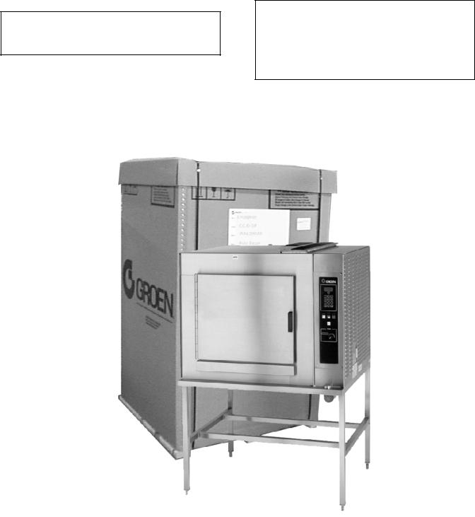
Your Convection Combo™ will be completely assembled in a heavy shipping carton (CC10-G) or wooden crate (CC20-G), and attached to a skid. On receipt, inspect the carton or crate carefully for exterior damage.
CAUTION
SHIPPING STRAPS ARE UNDER TENSION AND CAN SNAP BACK WHEN CUT.
Carefully cut the straps around the carton and detach the sides of the carton from the skid. Pull the carton up off the unit. Be careful to avoid personal injury or equipment damage from nails and sharp pieces of wood or staples which might be left in carton walls.
Write down the model number, serial number and installation date and keep this information for future reference. Space for these entries is provided at the top of the Service Log in the back of this manual.
CAUTION
THIS UNIT IS VERY HEAVY. YOU SHOULD GET HELP AS NEEDED AND USE MATERIAL HANDLING EQUIPMENT TO REMOVE THE UNIT FROM THE SKID AND MOVE IT TO ITS PLACE OF INSTALLATION.
When starting installation, use material handling equipment to lift the unit straight up off the skid. Check packing materials to make sure loose parts are not discarded with the material.
The unit will be delivered in either a heavy carton (CC10-G and CC20-G) or a heavy wooden crate ((2)CC10-G and (2) CC10-G), strapped to a wooden skid. (CC20-GF pictured)
5
OM-CC-G
Water Conditioning
It is essential to supply the steam generator with water that will not form scale. Even though the steam generator is engineered to minimize scale formation, scale development depends on the hardness of your water and the number of hours you operate the equipment.
In some areas, water is low enough in mineral content to avoid scale formation. But most water supplies are full of minerals which form scale. It is this scale which could lead to an early component failure.
Your water utility can tell you about the minerals in your water. The water going to the steam generator should have between 30 and 40 parts per million (ppm) total dissolved solids (TDS) and should have a pH (acidity rating) of 7.0 to 9.0. Please follow these simple precautions:
1.Do not rely on unproven water treatments which are sold for scale prevention or scale removal. They don’t always work. The best way to prevent scale is to supply the purest possible water (30-40 ppm TDS).
2.If your water contains scale-forming minerals, as most water does, use a well-maintained water softener. Whether an exchangeable softener cartridge or a regenerating system is chosen, a regular exchange schedule is essential.
3.Installing a water meter between the softener and the steamer will provide an accurate gauge of water use, and will help determine when to exchange cartridges or regenerate the softener. Using a water softener will provide longer generator life, higher steam capacity, and reduce maintenance requirements.
4.If you notice a slowdown in steam production, have the unit checked for scale build-up. Heavy scale reduces the unit’s ability to boil water.
MINIMIZE SCALE PROBLEMS, BY USING AND MAINTAINING A SOFTENER, AND BY CLEANING THE STEAM GENERATOR REGULARLY.
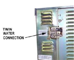
Groen Convection Combo™ ovens are also available with an option for two separate water connections — one for the steam generator (soft water), the other for the spray condenser (untreated water). The steam generator only uses 14 to 31% of a combination oven’s water.
Since softener systems are typically sized by total GPH (gallons per hour), the second connection could reduce treatment requirements by up to 80%, resulting in significant savings.
Optional separate water connections for steam generator and drain spray condenser.
6

OM-CC-G
Installation and Start-Up
WARNING
THE UNIT MUST BE INSTALLED BY PERSONNEL WHO ARE QUALIFIED TO WORK WITH ELECTRICITY AND PLUMBING. IMPROPER INSTALLATION CAN CAUSE INJURY TO PERSONNEL AND/OR DAMAGE TO THE EQUIPMENT. THE UNIT MUST BE INSTALLED IN ACCORDANCE WITH APPLICABLE CODES.
CAUTION
DO NOT INSTALL THE UNIT WITH THE RIGHT SIDE VENTS BLOCKED OR WITHIN 12 INCHES OF A HEAT SOURCE (SUCH AS A BRAISING PAN, DEEP FRYER, CHAR BROILER OR KETTLE). DO NOT INSTALL TO THE LEFT OF ANY OPEN-FLAME EQUIPMENT.
TO AVOID DRAINAGE PROBLEMS, LEVEL THE UNIT FRONT TO BACK.
Installation
1.Mounting
If you wish to install a Convection Combo™ on top of another, you should obtain a double stacked unit from the factory.
The unit must be installed in an adequately vented room with a provision for an ample air supply to the unit. The unit must be installed completely under a ventilation hood, since flue products exit the appliance over its entire depth. Anything which might restrict the flow of air for ventilation and combustion must be removed. Do not obstruct the flue cover or any front, side, top or rear vents after installation. The area directly around the Convection Combo™ must be cleared of all combustible material.
Installation must comply with local codes, or in the absence of local codes, conform to the National Fuel Gas Code ANSI Z223.1 - latest edition, including:
“The appliance and its individual shut-off valve must be disconnected from the gas supply piping system during any pressure testing of that system at test pressures in excess of ½ psig (3.45 kPa). The appliance must be isolated from the gas supply by closing its individual manual shut-off valve during any pressure testing of the gas supply piping system at test pressures equal to or less than ½ PSI (3.45 kPa).”
2.Gas Supply Connections
WARNING
THIS UNIT IS FOR COMMERCIAL USE. NEVER USE HOME OR RESIDENTIAL GRADE GAS CONNECTIONS. THEY DO NOT MEET GAS CODES AND COULD BE HAZARDOUS.
Connect to the gas supply using ¾ NPT pipe or an approved equivalent. Although the immediate connection to the Convection Combo™ is ¾ NPT, the gas supply piping must be large enough to provide 93,000 BTU/hour for each CC10 cooking chamber or 186,000 BTU/hour for each CC20 cooking chamber. Supply pressure must be at least 5" W.C. (maximum 14" W.C.) for natural gas or 12" W.C. (maximum 14" W.C.) for LP gas. In Canada, the installation must conform to the Canadian Gas Code, CAN 1- B149, Installation Codes for Gas Burning Appliances and Equipment, and/or local codes.
For units on casters, complete the gas supply connection using only connectors that meet the standards for movable gas appliances, ANSI Z21.69 — latest edition. Restrain movement of the unit by attaching a cable or chain to the eyelet (provided at the back of the frame) and anchoring the cable or chain to the wall or floor. Make the length and location of the cable such that the unit cannot pull on the gas connection while the cable is connected.
3.Electrical Supply Connection
For a single oven, or for each oven in a double stacked unit, provide 115 VAC, 60 Hz, one phase, 15 AMP service. Local codes and/or the National Electrical Code should be observed in accordance with ANSI/NFPA 70-1987 (or latest edition). AN ELECTRICAL GROUND IS REQUIRED. The electrical schematic is located in the service compartment and this manual. Maximum load per oven is 5½ AMPs. In Canada provide electrical service in accordance with the Canadian Electrical Code, CSA C22.1 Part 1, and/or local codes.
7

OM-CC-G
4.Water Supply Connection
A check valve (anti-siphonage device) must be installed in the incoming cold water line in keeping with local plumbing codes. Water line pressure should be between 30 and 60 PSI (210 and 410 kPa). A pressure regulator is required above 60 PSI (410 kPa).
A ¾ inch (19 mm) NH connector is required to connect the water supply to the water inlet valve. The water feed line diameter may not be less that ½ inch (13 mm). Use a washer (or if necessary, two washers) in the hose connection. Do not allow the connection to have any leak, no matter how small.
If you have a CC10-G which is equipped with the optional split water supply, the steam generator supply must be able to fill the generator with 3 gallons (11.4 liters) of water in 5 minutes. The make-up water rate is 0.06 gallons per minute (0.2 liters per minute). Condensate spray water rate is 0.34 gallons per minute (1.3 liters per minute) at 30 PSI (210 kPa). These requirements apply to each steam generator in model (2)CC10-G.
If you have a CC20-G which is equipped with the optional split water supply, the steam generator water supply must be able to fill the generator with 5 gallons (19 liters) of water in 5 minutes. The make-up water rate is 0.12 gallons per minute (0.45 liters per minute). Condensate spray water rate is 0.7 gallons per minute (2.6 liters per minute) at 30 PSI (210 kPa). These requirements apply to each steam generator in model (2)CC20-G.
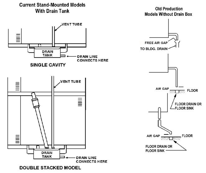
4.Drain Connection
a.Unit Without Drain Tank
A 1½ inch (4 cm) ID (CC10-G) or 2 inch (5 cm) ID hose (CC20-G) may be attached to the supplied drain outlet with a clamp. Do not use plastic pipe, because the drain must withstand very hot water.
WARNING:
DO NOT CONNECT THE OVEN DRAIN DIRECTLY TO A BUILDING DRAIN.
There must be a free air gap between the end of the hose and the building drain. The free air gap should be as close as possible to the unit’s drain. There must also be no
other elbows or other restrictions between the unit drain and the free air gap.
CAUTION
DO NOT USE PLASTIC PIPE. DRAIN MUST BE RATED FOR VERY HOT WATER.
WARNING BLOCKING THE DRAIN IS HAZARDOUS.
On a double stacked unit, there must be a minimum of two inches free air gap on each drain, as close to each oven as possible. Double stacked units may only share a common drain hose downstream of both free air gaps.
Install the drain line with a constant downward pitch.
IMPORTANT: Do not allow any water traps in the line. A trap can cause pressure to build up inside the cavity during steaming, which will make the door gasket leak.
NOTE: Improper drain connection will void the warranty.
b.Units With Drain Tank
A hose may be attached to the supplied drain elbow with a clamp. Use 1½ inch ID hose for CC10-G or 2" ID hose for CC20-G. The hose may be connected directly to a building drain since the drain tank has an air vent, which eliminates the need for a free air gap at the building drain.
Do not block the air vent in any way. Do not attach anything to the vent tube or reduce its size.
Do NOT use plastic pipe in the drain line, because the drain must withstand very hot water.
8

OM-CC-G
Convection Combo™ Utility Connections
NOTE: Remove right side panel to make connections at terminal block in rear of control compartment.
9
OM-CC-G
Proper Drain Line Connections
10
 Loading...