


Groen DHT-20, DH-20, DHT-40, DHT-60, DHT-80 User Manual
...OPERATOR MANUAL
IMPORTANT INFORMATION, KEEP FOR OPERATOR
1055 Mendell Davis Drive, Jackson, MS 39272 888-994-7636, fax 888-864-7636 unifiedbrands.net
THIS MANUAL MUST BE RETAINED FOR FUTURE REFERENCE. READ, UNDERSTAND AND FOLLOW THE INSTRUCTIONS AND WARNINGS CONTAINED IN THIS MANUAL.
FOR YOUR SAFETY Instructions to be followed in the event user smells gas. This information shall be obtained by consulting your local gas supplier. As a minimum, turn off the gas and call your gas company and your authorized service agent. Evacuate all personnel from the area.
WARNING Improper installation, adjustment, alteration, service or maintenance can cause property damage, injury or death. Read the installation, operating and maintenance instructions thoroughly before installing or servicing this equipment.
NOTIFY CARRIER OF DAMAGE AT ONCE It is the responsibility of the consignee to inspect the container upon receipt of same and to determine the possibility of any damage, including concealed damage. Unified Brands suggests that if you are suspicious of damage to make a notation on the delivery receipt. It will be the responsibility of the consignee to file a claim with the carrier. We recommend that you do so at once.
Manufacture Service/Questions 888-994-7636.
EQUIPMENT DESCRIPTION
PART NUMBER 174845, REV. E (04/19)
This manual provides information for:
STEAM JACKETED KETTLE MODELS DH(T)-20/40/60/80 (C,A,C2T™) DOMESTIC
REFERENCES |
NATIONAL FIRE PROTECTION ASSOCIATION |
60 Battery March Park |
|
CSA INTERNATIONAL |
Quincy, Massachusetts 02269 |
8501 East Pleasant Valley Road |
|
Cleveland, Ohio 44131 |
NFPA/54 -Installation Gas Appliances & |
|
Piping |
NSF INTERNATIONAL |
NFPA/70 - The National Electric Code |
798 N. Dixboro Rd. |
|
P.O. Box 130140 |
ZEP MANUFACTURING COMPANY |
Ann Arbor, Michigan 48113-0140 |
1310-T Seaboard Industrial Boulevard |
|
Atlanta, Georgia 30318 |
UNDERWRITERS LABORATORIES, INC. |
|
333 Pfingsten Road |
AMERICAN NATIONAL STANDARDS INST., INC. |
Northbrook, Illinois 60062 |
1430 Broadway |
|
New York, New York 10018 |
KLENZADE SALES CENTER ECOLAB, Inc. |
|
370 Wabasha |
Z223.1-1984 - National Fuel Gas Code |
St. Paul, Minnesota 55102 |
Z21.30 - Installation Gas Appliances & Piping |
The Groen DH is a floor-mounted, tilting, steam jacketed kettle with a thermostatically or electronically controlled, self-contained, gas-heated steam source and appropriate controls, mounted on a sturdy base. The Model DH is available in 20, 40, 60 or 80 gallon capacities.
The body of the DH Kettle is constructed of stainless steel, welded into one solid piece. The kettle is furnished with a reinforced rim and a butterfly shaped pouring lip. It has a steam jacket which is ASME shop inspected and registered with the national board for working pressures up to 50 PSI. Kettle finish is 180 emery grit on the inside and bright high buff polish on the outside.
The kettle is tilted with a hand crank to pour out its contents. Stainless steel panels enclose the controls and the base. Four stainless steel tubular legs support the unit. Bullet or flanged feet on each of the legs can be adjusted to level the kettle. Standard DHT units include a two inch tangent draw-off valve.
The self-contained steam source is heated by propane or natural gas. Ignition is electronic.
The kettle is charged at the factory with chemically pure water which contains rust inhibitors. The steam source provides kettle temperatures of 150º to approximate-
ly 295ºF (65 to 150ºC). Unit controls include a thermostat or controller, pressure gauge, safety valve, pressure limit control, low water cut-off, power switch and gas regulator valve. The gas supply shuts off automatically when the kettle is tilted.
The unit must be specified for use with natural or propane gas. Service connections for gas and electricity are required. Standard power supply is 115 Volt. Alternate single-phase voltages (208-240V) are available.
Options available include:
1.Two inch tangent drawoff standard on DHT models
2.Strainers, solid disk, 1/4 or 1/8 inch holes
3.No. 31 lift-off cover
4.No. 51 counterbalanced cover w/actuator*
5.Basket Inserts (Tri-BC)
6.Water fill faucets with swing spout
7.Kettle Brush Kit
Information contained in this document is known to be current and accurate at the time of printing/creation. Unified Brands recommends referencing our product line websites, unifiedbrands.net, for the most updated product information and specifications. © 2019 Unified Brands.All Rights Reserved. Unified Brands is a wholly-owned subsidiary of Dover Corporation.

IMPORTANT - READ FIRST - IMPORTANT
CAUTION: BE SURE ALL OPERATORS READ, UNDERSTAND AND FOLLOW THE OPERATING INSTRUCTIONS, CAUTIONS, AND SAFETYINSTRUCTIONS CONTAINED IN THIS MANUAL.
WARNING: THIS UNIT IS INTENDED FOR USE IN THE COMMERCIAL HEATING, COOKING AND HOLDING OF WATER AND FOOD PRODUCTS, PER THE INSTRUCTIONS CONTAINED IN THIS MANUAL. ANY OTHER USE COULD RESULT IN SERIOUS PERSONAL INJURY OR DAMAGE TO THE EQUIPMENT AND WILL VOID WARRANTY.
WARNING: KETTLE MUST BE INSTALLED BY PERSONNEL QUALIFIED TO WORK WITH ELECTRICITY AND PLUMBING. IMPROPER INSTALLATION CAN RESULT IN INJURY TO PERSONNEL AND/OR DAMAGE TO EQUIPMENT.
DANGER: ELECTRICALLY GROUND THE UNIT AT THE TERMINAL PROVIDED. FAILURE TO GROUND UNIT COULD RESULT IN ELECTROCUTION AND DEATH.
WARNING: DO NOT CONNECT ANY PIPING TO THE POP SAFETY VALVE. THE VALVE MUST BE FREE TO VENT STEAM AS NEEDED. THE ELBOW ATTACHED TO THE SAFETY VALVE SHOULD POINT TO THE FLOOR. IMPROPER INSTALLATION WILL VOID WARRANTY.
WARNING: AVOID ALL DIRECT CONTACT WITH HOT EQUIPMENT SURFACES. DIRECT SKIN CONTACT COULD RESULT IN SEVERE BURNS.
WARNING: AVOID ALL DIRECT CONTACT WITH HOT FOOD OR WATER IN THE KETTLE. DIRECT CONTACT COULD RESULT IN SEVERE BURNS.
CAUTION: DO NOT OVER FILL THE KETTLE WHEN COOKING, HOLDING OR CLEANING. KEEP LIQUIDS A MINIMUM OF 2-3” (5-8 cm) BELOW THE KETTLE BODY RIM TO ALLOW CLEARANCE FOR STIRRING, BOILING AND SAFE PRODUCT TRANSFER.
WARNING: TAKE SPECIAL CARE TO AVOID CONTACT WITH HOT KETTLE BODY OR HOT PRODUCT WHEN ADDING INGREDIENTS, STIRRING OR TRANSFERRING PRODUCT TO ANOTHER CONTAINER.
WARNING: WHEN TILTING KETTLE FOR PRODUCT TRANSFER:
1)USE CONTAINER DEEP ENOUGH TO CONTAIN AND MINIMIZE SPLASHING.
2)PLACE CONTAINER ON STABLE, FLAT SURFACE, AS CLOSE TO KETTLE AS POSSIBLE.
3)DO NOT OVER FILL CONTAINER. AVOID DIRECT SKIN CONTACT WITH HOT CONTAINER AND ITS CONTENTS.
CAUTION: KEEP FLOORS IN FRONT OF KETTLE WORK AREA CLEAN AND DRY. IF SPILLS OCCUR, CLEAN IMMEDIATELY, TO AVOID SLIPS OR FALLS.
WARNING: FAILURE TO CHECK SAFETY VALVE OPERATION PERIODICALLY COULD RESULT IN PERSONAL INJURY AND/OR DAMAGE TO EQUIPMENT.
WARNING: WHEN TESTING SAFETY VALVE, AVOID ANY EXPOSURE TO THE STEAM BLOWING OUT OF THE SAFETY VALVE. DIRECT CONTACT WITH STEAM COULD RESULT IN SEVERE BURNS.
WARNING: TO AVOID INJURY, READ AND FOLLOW ALL PRECAUTIONS STATED ON THE LABEL OF THE WATER TREATMENT COMPOUND.
WARNING: BEFORE REPLACING ANY PARTS, DISCONNECT THE UNIT FROM THE ELECTRIC POWER SUPPLY AND CLOSE THE MAIN GAS VALVE. ALLOW FIVE MINUTES FOR UNBURNED GAS TO VENT.
WARNING: KEEP WATER AND SOLUTIONS OUT OF CONTROLS AND ELECTRICAL EQUIPMENT. NEVER SPRAY OR HOSE THE SUPPORT HOUSING OR ELECTRICAL CONNECTIONS.
CAUTION: MOST CLEANERS ARE HARMFUL TO THE SKIN, EYES, MUCOUS MEMBRANES AND CLOTHING. PRECAUTIONS SHOULD BE TAKEN. WEAR RUBBER GLOVES, GOGGLES OR FACE SHIELD AND PROTECTIVE CLOTHING. CAREFULLY READ THE WARNINGS AND FOLLOW THE DIRECTIONS ON THE LABEL OF THE CLEANER TO BE USED.
CAUTION: USE OF ANY REPLACEMENT PARTS OTHER THAN THOSE SUPPLIED BY GROEN OR THEIR AUTHORIZED SERVICE AGENTS CAN CAUSE OPERATOR INJURY AND DAMAGE TO THE EQUIPMENT, AND WILL VOID ALL WARRANTIES.
IMPORTANT: SERVICE PERFORMED BY OTHER THAN FACTORY AUTHORIZED PERSONNEL WILL VOID WARRANTIES.
WARNING: DO NOT HEAT AN EMPTY KETTLE. EXCESSIVE STEAM PRESSURE COULD DEVELOP.
NOTICE: IT IS RECOMMENDED THAT AN INSTANT-READ THERMOMETER BE USED TO CHECK THE INTERNAL TEMPERATURE THROUGHOUT THE COOKING PROCESS AND AFTER THE COOKING PROCESS HAS BEEN COMPLETED TO ENSURE THE FOOD HAS BEEN COOKED SUFFICIENTLY.
PERFORMANCE DATA
|
|
Kettle |
|
|
Firing |
Energy |
|
|
Kettle |
Base |
Base |
into Prod- |
|||
Model |
Body |
Rate Per |
|||||
Capacity |
Width |
Depth |
uct Per |
||||
|
Diameter |
Hour |
|||||
|
|
|
|
Hour |
|||
|
|
|
|
|
|
||
|
|
|
|
|
|
|
|
DH/DHT-20 |
20 Gal. |
20 inches |
35 inches |
29 inches |
72,000 |
44,140 |
|
|
|
|
|
||||
(C,A,C2T) |
75 liter |
508 mm |
889 mm |
736 mm |
BTU |
BTU |
|
|
|
|
|||||
|
|
|
|
|
|
|
|
DH/DHT-40 |
40 Gal. |
26 inches |
47 inches |
29 inches |
100,000 |
65,000 |
|
|
|
|
|
||||
(C,A,C2T) |
150 liter |
660 mm |
1194 mm |
736 mm |
BTU |
BTU |
|
|
|
|
|||||
|
|
|
|
|
|
|
|
DH/DHT-60 |
60 Gal. |
30 inches |
47 inches |
29 inches |
150,000 |
93,000 |
|
|
|
|
|
||||
(C,A,C2T) |
225 liter |
762 mm |
1194 mm |
736 mm |
BTU |
BTU |
|
|
|
|
|||||
|
|
|
|
|
|
|
|
DH/DHT-80 |
80 Gal. |
34inches |
52 inches |
37-1/2 |
150,000 |
93,000 |
|
inches |
|||||||
|
|
|
|||||
(C,A,C2T) |
|
|
|
BTU |
BTU |
||
|
|
|
|
||||
302 liter |
863 mm |
1320 mm |
952 mm |
||||
|
|
|
|||||
|
|
|
|
|
|
|
INSPECTION & UNPACKING
CAUTION: SHIPPING STRAPS ARE UNDER TENSION AND CAN SNAP BACK WHEN CUT. TAKE CARE TO AVOID PERSONAL INJURY OR DAMAGE TO THE UNIT BY STAPLES LEFT IN THE WALLS OF THE CARTON.
CAUTION: THIS UNIT WEIGHS BETWEEN 535 AND 978 POUNDS (245 TO 400 KG) DEPENDING ON SIZE. INSTALLER SHOULD USE PROPER EQUIPMENT TO LIFT SAFELY.
The unit arrives completely assembled, except for the tilting handle on hand tilt models which is shipped inside the kettle. The unit is strapped on a skid and in a heavy carton. Inspect the carton carefully for damage. Open the container and check the unit for hidden damage. Report shipping damage or shipment errors to the delivery agent.
Write down the model number, serial number, and installation date for your unit at the top of the Service Log at the end of this manual. Keep this manual with the unit.
When installation is to begin, carefully cut any straps which hold the unit on the skid. Lift the unit straight up off the skid. Examine packing materials to be sure loose parts are not discarded with the materials.
2 OM-DH(T)-20/40/60/80 (C,A,C2T™) Domestic
INSTALLATION
WARNING: THE UNIT MUST BE INSTALLED BY PERSONNEL WHO ARE QUALIFIED TO WORK WITH GAS, ELECTRICITY AND PLUMBING. IMPROPER INSTALLATION CAN CAUSE INJURY TO PERSONNEL AND/OR DAMAGE TO THE EQUIPMENT. THE UNIT MUST BE INSTALLED IN ACCORDANCE WITH APPLICABLE CODES. THE UNIT MUST BE INSTALLED BY A LICENSED PLUMBER OR GAS FITTER WHEN INSTALLED WITHIN THE COMMONWEALTH OF MASSACHUSETTS.
DANGER: ELECTRICALLY GROUND THE UNIT AT THE TERMINAL PROVIDED. FAILURE TO GROUND UNIT COULD RESULT IN ELECTROCUTION AND DEATH.
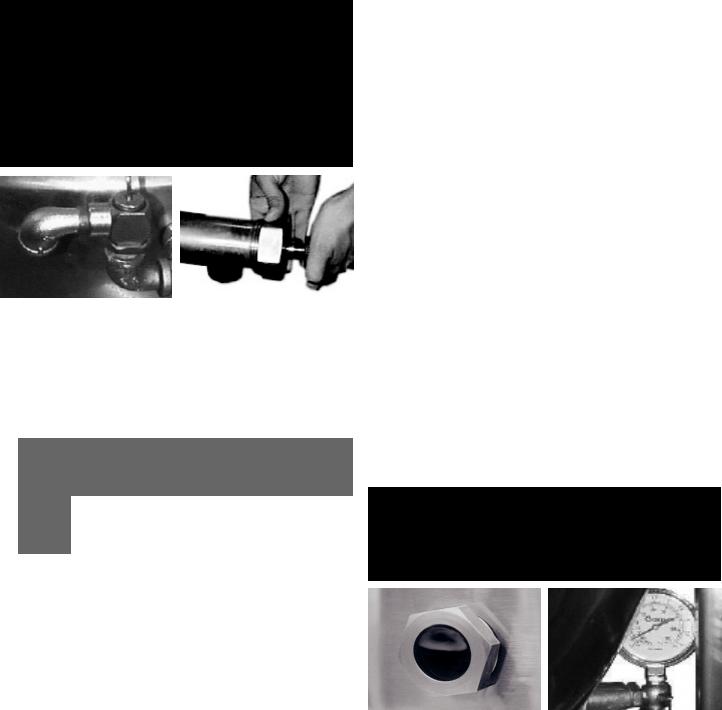
WARNING: DO NOT CONNECT ANY PIPING TO THE PRESSURE RELIEF VALVE. THE VALVE MUST BE FREE TO VENT STEAM AS NEEDED. IMPROPER INSTALLATION WILL VOID THE WARRANTY! THE ELBOW ATTACHED TO THE PRESSURE RELIEF VALVE MUST POINT TO THE FLOOR.
The open end of the pressure relief valve |
When attaching the draw-off |
elbow must face downward. |
valve, hand-tighten the nut. |
For efficient performance the kettle must be installed in a well-ventilated area. Items which might restrict or obstruct the flow of air for combustion and ventilation must be removed. The area directly around the appliance must be free of combustible materials.
1.Installation can be on a combustible or noncombustible floor. Clearances should be per table.
|
MINIMUM |
MINIMUM |
|
|
CLEARANCE FROM |
CLEARANCE FROM |
RECOMMENDED |
|
COMBUSTIBLE |
NON-COMBUSTIBLE |
CLEARANCES |
|
WALLS |
WALLS |
|
|
|
|
|
Left Side |
6 in. |
0 in. |
6 in. |
|
|
|
|
Right Side |
6 in. |
0 in. |
10 in. |
|
|
|
|
Rear |
10 in. |
10 in. |
12 in. |
|
|
|
|
2.The kettle should be installed in an adequately ventilated room with provision for adequate air supply. The ventilation must employ a vent hood and exhaust fan with no direct connection between the vent duct and the kettle flue. Do not obstruct the flue or vent duct after installation.
3.Set the kettle in place and level it using a spirit level on the bar rim, by turning the bullet or flange feet to adjust leg length. Allow clearance around the unit for cleaning, maintenance and service.
4.Complete the piping to the gas service main with ½” line or approved equivalent.
5.Provide 115 vac, 60 Hz, single phase 5 AMP electrical service. The unit may also be ordered for alternate electric service of 208 VAC - 240 VAC. Observe local codes and/or The National Electrical Code in accordance with ANSI/ NFPA 70 (current edition), or the Canadian Electrical Code, CSA C22.2 (current edition), as applicable. Use the wiring diagram inside the service panel and at the rear of this manual.
6.Core probe storage bracket (C2T models only)
a.It is recommend that the core probe storage bracket be installed on the control console. It is not recommend that the core probe storage bracket be installed on the kettle body or cover.
b.To obtain proper adhesion, the bonding surface must be unified, clean and dry. Clean the bonding surface with rubbing alcohol and allow the surface to dry. Next firmly apply pressure to the storage bracket to help improve bond strength. After application, the bond strength will increase as the adhesive flows onto the surface. At room temperature, approximately
50% of the ultimate strength will be achieved after 20 minutes, 90% after 24 hours and 100% after 72 hours.
7.Bring electrical service through the entrance at the rear of the support housing with a ½ inch conduit connector. Make a watertight connection with the incoming lines.
8.Electrically ground the unit at the terminal provided.
9.After the kettle has been connected to the gas supply, check all gas joints for leaks. DO NOT USE FLAME TO CHECK FOR LEAKS. A thick soap solution or other suitable leak detector should be employed.
10.The gas supply and unit’s installation must conform with local codes or in the absence of local codes, with the National Fuel Gas Code, ANSI Z223.1/NFPA 54 (current edition), or the Natural Gas and Propane Installation Code CSA 149.1(current edition), as applicable. Additionally following must be complied with: THE AREA DIRECTLY AROUND THE APPLIANCE MUST BE CLEARED OF ALL COMBUSTIBLE MATERIAL. FAILURE TO FOLLOW THESE INSTRUCTIONS CAN CAUSE BODILY INJURY AND /OR PROPERTY DAMAGE. The appliance and its individual shut-off valve must be disconnected from the gas supply piping system during any testing at pressures in excess of ½ PSI (3.45 kPa). The appliance must be isolated from the gas supply piping system by closing its individual manual shut-off valve during any pressure testing at or less than ½ PSI (3.45 kPa).
11.Confirm that the jacket water level is between the gauge glass markers or inside the sight glass port. If the level is low, follow instructions under Jacket Filling and Water Treatment in this manual.
12.The open end of the elbow on the outlet of the safety valve must face downward. If it does not, turn it to the correct position.
13.For units with optional tangent draw-off: Assemble the tangent draw-off by placing the large nut over the draw-off valve and inserting it into the draw-off tube. ONLY HAND-TIGHTEN THE NUT to complete installation.
INITIAL START-UP
WARNING: WATER IS EXTREMELY HOT AND CAN CAUSE SEVERE BURNS. AVOID CONTACT WITH HOT WATER WHEN EMPTYING UNIT.
WARNING: DO NOT STAND ON OR APPLY UNNECESSARY WEIGHT OR PRESSURE ON THE KETTLE FRONT OR POURING LIP. THIS COULD RESULT IN THE OVERLOAD AND FAILURE OF THE TILT MECHANISM, AND POSSIBLE SERIOUS INJURY AND BURNS TO THE OPERATOR AND OTHERS.
Correct water level (Model DH-80E and |
Each day confirm the jacket water |
DHT-80 only). |
level by checking the water gauge. |
After the kettle has been installed, the installer should test to ensure that it is operating correctly.
1.Remove literature and packing materials from the interior and exterior of the unit.
2.If the unit is equipped with a draw-off valve (product outlet), clean out any material which might clog or damage the draw-off.
3.Confirm that the tilting mechanism is operating properly by tilting the kettle through its full range. Then return the kettle to the upright position.
4.Turn on the electrical service to the unit.
5.Pour 1-2 gallons of water into the kettle.
3 OM-DH(T)-20/40/60/80 (C,A,C2T™) Domestic

6.Following “To Start Kettle” instructions in the “Operation” section in this manual, begin heating the water at the highest controller setting. The heat indicator light should come on, and heating should continue until the water boils.
If the kettle functions as described, it is ready for use. If the unit does not operate as designed, contact an authorized Service Agent.
OPERATION
WARNING: WHEN TILTING KETTLE:
1)WEAR PROTECTIVE OVEN MITT AND PROTECTIVE APRON.
2)USE DEEP CONTAINER TO CONTAIN AND MINIMIZE PRODUCT SPLASHING.
3)PLACE CONTAINER ON STABLE, FLAT SURFACE, AS CLOSE TO KETTLE AS POSSIBLE.
4)STAND TO RIGHT OF KETTLE WHILE POURING — NOT DIRECTLY IN POUR PATH OF HOT CONTENTS.
5)POUR SLOWLY, MAINTAINING CONTROL OF KETTLE, AND RETURN KETTLE BODY TO UPRIGHT POSITION AFTER CONTAINER IS FILLED OR TRANSFER IS COMPLETE.
6)DO NOT OVERFILL CONTAINER. AVOID SKIN CONTACT WITH HOT CONTAINER AND ITS CONTENTS.
WARNING: AVOID ALL DIRECT CONTACT WITH HOT SURFACES AND HOT FOOD OR WATER IN
THE KETTLE. DIRECT CONTACT COULD RESULT IN SEVERE BURNS.
CAUTION: DO NOT OVERFILL THE KETTLE WHEN COOKING, HOLDING OR CLEANING. KEEP LIQUIDS AT LEAST 2-3” (5-8 CM) BELOW THE KETTLE RIM TO ALLOW CLEARANCE FOR STIRRING, BOILING AND SAFE PRODUCT TRANSFER.
WARNING: AVOID ALL DIRECT CONTACT WITH HOT FOOD OR WATER IN THE KETTLE. DIRECT CONTACT COULD RESULT IN SEVERE BURNS.
CAUTION: HEATING AN EMPTY KETTLE MAY CAUSE THE RELEASE OF STEAM FROM THE PRESSURE RELIEF VALVE.
CAUTION: DO NOT TILT KETTLE BODY WITH COVER OR BASKET INSERT IN PLACE. COVER MAY SLIDE OFF, CAUSING INJURY TO OPERATOR.
CAUTION: ANY POTENTIAL USER OF THE EQUIPMENT MUST BE TRAINED IN SAFE AND CORRECT OPERATING PROCEDURES.
WARNING: KEEP AREA AROUND KETTLE FREE AND CLEAR OF ALL COMBUSTIBLE MATERIALS. DO NOT ATTEMPT TO LIGHT ANY BURNER WITH A FLAME.
Classic Control |
Advanced Control |
Cook2Temp Control |
CONTROLS
1.Classic Control (-C) Models
a.The manual gas shut-off valve supplies inlet gas to the unit.
b.Lighted Power ON switch located on the control console. Controls main power to the unit.
c.The temperature knob, located on the control console, is used to set the kettle heat values between 1 and 10.
d.Heating indicator light located on the control console, lights when the controller sends call to open the main gas valve and will cycle on and off once the unit reaches set temperature. If the unit is tilted, the main gas valve will be disabled and the light will turn off until the unit is returned to the cooking position.
e.A LOW WATER indicator light, located on the control console, illuminates
when the jacket water falls below acceptable levels. When lit, the main gas valve is disabled and will not function until the jacket water is refilled using the procedure in this manual.
f.Crank tilt – a handle controls the worm and gear mechanism that smoothly tilts the kettle body and holds it in the desired position.
2.Advanced Control (-A) Models
a.The manual gas shut-off valve supplies inlet gas to the unit.
b.Lighted Power ON switch located on the control console. Controls main power to the unit.
c.The temperature knob, located on the control console, is used to set the kettle heat values between 1.0 and 10.0. The current setting will be reflected on the display.
d.Heating indicator light located on the control console, lights when the controller sends call to open the main gas valve and will cycle on and off once the unit reaches set temperature. If the unit is tilted, the main gas valve will be disabled and the light will turn off until the unit is returned to the cooking position.
e.A LOW WATER indicator light, located on the control console, illuminates when the jacket water falls below acceptable levels. When lit, the main
gas valve is disabled and will not function until the jacket water is refilled using the procedure in this manual.
f.SET TnnP Mode - Allows power to the controller and gas to the pilot without the kettle heating; the kettle will heat once the LOW TEMP, MANUAL or HIGH TEMP button is selected.
g.LOW TEMP Button – Used to set operating temperature of the kettle at a preset low intensity (default = 2.0). Can be pressed at any time during operation of the unit to change the set temperature to the preset value except when there is an active TIMER enabled.
h.MANUAL Mode button – Enables the user modify the desired cooking temperature of the kettle (between 1.0 and 10.0) using the temperature knob and display (default = 5.0). The operator will press the MANUAL button and set the desired temperature using the temperature knob and display. Once the desired intensity is displayed, the user may either press the MANUAL button again or wait 5 seconds and the set temperature will be accepted by the controller and locked in. After the set temperature is accepted, it may be changed at any time by pressing the MANUAL button and resetting the temperature using the same process above.
i.HIGH TEMP button – Used to set operating temperature of the kettle at a preset high intensity (default = 7.0). Can be pressed at any time during operation of the unit to change the set temperature to the preset value except when there is an active TIMER enabled.
1.TIMER button - once the appropriate set temperature is selected using the HIGH TEMP, MANUAL or LOW TEMP buttons; a countdown timer can be set to remind the user when the cooking process is completed. Range – 1 minute to 10 hours
2.When the timer expires:
a.the set temperature will automatically change to the LOW TEMP setting and will continue at this setting until the user changes the temperature via MANUAL or HIGH TEMP buttons
b.An audible alarm will notify the user that attention is required, the alarm will continue to sound until the user presses the TIMER button.
3.An active timer can be cancelled by pressing and holding the TIMER button for 5 secs.
4.Set temp can be changed during an active timer by pressing the MANUAL button and adjusting the set temp using the Temperature knob and display.
5.HIGH TEMP and LOW TEMP presets cannot be used to change the setpoint once a TIMER has started.
4 OM-DH(T)-20/40/60/80 (C,A,C2T™) Domestic
j.READY alarm – The control will sound 3 beeps when the unit has reached within 20 degrees of set point during pre-heat and when a higher set temperature is selected.
k.Crank tilt – a handle controls the worm and gear mechanism that smoothly tilts the kettle body and holds it in the desired position.
3.Cook2Temp™ Control (-C2T™) Models
a.Lighted Power ON switch located on the control console. Controls main power to the unit.
b.Heating indicator light located on the control console, lights when the controller calls for the main gas valve to open and will cycle on and off once the unit reaches set temperature. If the unit is tilted, the call for heat will be interrupted and the light will turn off until the unit is returned to the cooking position.
c.Low Water indicator light, located on the control console, lights when the jacket water falls below the acceptable levels. When lit, the main gas valve is disabled and will not function until the jacket water is refilled using the procedure in the operator manual.
d.Set Mode – Allows power to the controller and the pilot to light, but the main burners remain off. The kettle will heat once the LOW TEMP, MANAUAL or HIGH TEMP button is selected.
e.LOW TEMP Button – Used to set a unit temperature of the kettle at a preset low temperature (default = 175°F). Can be pressed at any time during operation of the unit to change the unit temperature to the preset value except when there is an active TIMER or an active Cook2Temp.
f.MANUAL Button – Enables the user to modify the unit temperature of the kettle (between 100°F and 287°F) using the temperature knob and display (default = 183°F). The operator will press the MANUAL button and then select the desired unit temperature using the temperature knob and display. Once the desired unit temperature is shown on the display, the user may either press the MANUAL button again or wait 5 seconds and the selected temperature will be accepted by the controller and locked in. After the selected temperature is accepted it may be changed at any time by pressing the MANUAL button and resetting the temperature using the same process as above except when there is an active AUTO Cook2Temp.
g.HIGH TEMP Button – Used to set unit temperature of the kettle at a preset high temperature (default = 287°F). Can be pressed at any time during operation of the unit to change the unit temperature to the preset value except when there is an active TIMER or an active Cook2Temp.
h.TIMER Button – Once the appropriate unit temperature is selected using the LOW TEMP, MANUAL or HIGH TEMP buttons, a countdown timer can be set to remind the user when the cooking process is completed.
1.Range – 1 minute to 10 hours.
2.When the timer expires:
a.The unit temperature will automatically change to the LOW TEMP setting and will continue at this setting until the user changes the temperature via MANUAL or HIGH TEMP buttons.
b.An audible alarm will notify the user that attention is required, the alarm will continue to sound until the user presses the TIMER button.
3.An active timer can be cancelled by pressing and holding the TIMER button for 5 seconds.
4.Unit temperature can be changed during an active timer by pressing the MANUAL button and adjusting the unit temperature using the temperature knob and display.
5.LOW TEMP and HIGH TEMP presets cannot be used to change the unit temperature once a TIMER has been enabled.
6.AUTO C2T and MANUAL C2T cannot be used once a timer has been enabled. The timer must first be cancelled and then AUTO C2T or MANUAL C2T can be enabled.
i.Ready alarm – The control will sound 3 beeps when the unit has reached within 20 degrees of set point during pre-heat and when a higher unit temperature is selected.
j.AUTO C2T Button – Enables the user to select a set product temperature (between 100°F and 230°F) using the temperature knob and display. The operator will press the AUTO C2T button and then select the set product temperature using the temperature knob and display. Once the set product temperature is shown on the display, the user may either press the AUTO C2T button again or wait 5 seconds and the selected temperature will be accepted by the controller and locked in. The unit temperature is automatically set 100°F above the set product temperature and cannot be changed at any time during an active AUTO C2T. After the set product temperature is accepted it may be changed at any time by first cancelling AUTO C2T and then using the same process as above to reset the temperature.
1.After the set product temperature is accepted by the controller and locked in. The unit will begin to heat and the display will scroll the actual product temperature followed by the set product temperature. This display will continue until the cook process has completed.
2.An active AUTO C2T can be cancelled by pressing and holding the AUTO C2T button for 5 seconds and the unit will then return to Set Mode.
3.LOW TEMP, MANUAL or HIGH TEMP presets cannot be used to change the unit temperature once there is an active AUTO C2T. The unit temperature is automatically set by the controller.
4.Once the set product temperature has been reached and held for 20 seconds consecutively the unit will automatically enable Hold Mode.
k.MANUAL C2T Button – Enables the user to select a set product temperature (between 100°F and 230°F) using the temperature knob and display. The operator will press the MANUAL C2T button and then select the set product temperature using the temperature knob and display. Once the set product temperature is shown on the display, the user may either press the MANUAL C2T button again or wait 5 seconds and the selected temperature will be accepted by the controller and locked in. Once the set product temperature has been accepted the user will be prompted to select a unit temperature via the MANUAL button. Once the set unit temperature is shown on the display, the user may either press the MANUAL C2T button again or wait 5 seconds and the selected temperature will be accepted by the controller and locked in. After the set product temperature and unit temperature are accepted the set product temperature may be changed at any time by first cancelling MANUAL C2T and then using the same process as above to reset the temperature.
1.After the set product temperature and unit temperature are accepted by the controller and locked in. The unit will begin to heat and the display will scroll the actual product temperature followed by the set product temperature. This display will continue until the cook process has completed.
2.An active MANUAL C2T can be cancelled by pressing and holding the MANUAL C2T button for 5 seconds and the unit will then return to Set Mode.
3.Unit temperature can be changed during an active MANUAL C2T by pressing the MANUAL button and adjusting the unit temperature using the temperature knob and display.
4.Once the set product temperature has been reached and held for 20 seconds consecutively the unit will automatically enable Hold Mode.
l.Hold Mode – Allows the unit to be controlled by the set product temperature and core probe.
1.Hold Mode is automatically enabled once a set product temperature has been reached and held for 20 seconds consecutively.
2.The display will scroll the actual product temperature followed by the hold timer.
5 OM-DH(T)-20/40/60/80 (C,A,C2T™) Domestic
3.If the actual product temperature falls below 142°F.
a.An audible alarm along with the display flashing the actual product temperature will notify the user that attention is required.
b.The alarm can be silenced by pressing any button.
c.The Alarm will resound every 10 minutes until the actual product temperature returns above 142°F.
4.If the actual product temperature rises 10°F above the set product temperature.
a.An audible alarm along with the display flashing the actual product temperature will notify the user that attention is required.
b.The alarm can be silenced pressing any button.
c.The alarm will resound every 10 minutes until the actual product temperature returns to within 10°F of the set product temperature.
5.At initial hold timer completion (default = 4 hours).
a.An audible alarm will be given for 5 seconds.
b.The alarm can be silenced by pressing any button.
c.The alarm will continue to resound every 15 minutes until Hold Mode is exited.
m.Display Descriptions
1.SEt nndE – Allows power to the controller without the pan heating, the pan will heat once the LOW TEMP, MANUAL or HIGH TEMP button is selected.
2.SEt PrOd tEnP – Indicates the desired finished product temperature.
3.SEt UnIt tEnP – Indicates the desired unit temperature.
4.SEt POInt – Indicates the set point for the desired finished product temperature.
5.ACt – Indicates the actual product temperature.
6.CPEr – Indicates a core probe error and will continue to display until the error has been resolved.
7.Prob – Indicates a unit probe error and will continue to display until the error has been resolved.
8.End – Indicates the cooking process has completed.
9.End HOLd – Indicates the initial hold timer has completed.
4.Cook2Temp™ Control (-C2T™) Core Probe
a.Ensure the core probe has been properly cleaned and sanitized before each use.
b.It is important that the tip of the core probe be placed correctly into the product since only the tip of the core probe senses the product temperature. Do this by inserting the core probe halfway into the product, positioning the tip at the center of the food mass, avoiding any bones. If placing into a semi-liquid or liquid product, occasionally stirring the product will ensure an accurate core probe reading. Do not let the core probe tip touch the edges, bottom or side of the unit.
c.If the core probe is not plugged into the receptacle when either the AUTO C2T or MANUAL C2T button is pressed then an audible alarm along with a core probe error message will notify the user that attention is required. Simply plug the core probe into the receptacle and continue with the input process.
d.If the core probe is unplugged from the receptacle during the cooking process or while in Hold Mode an audible alarm along with a core probe error message will notify the user that attention is required. Simply plug the core probe back into the receptacle and the cook process or Hold Mode will continue.
e.While the core probe is not in use ensure the sealing cap is properly protecting the panel mount connector. Failure to properly use the sealing cap could result in damage to the unit.
OPERATING PROCEDURE
1.To Start Kettle Heating:
a.EVERY DAY make sure that the jacket water level in the middle of the sight glass. If the level is too low, see “Jacket Filling and Water Treatment” in this manual.
b.Check the pressure/vacuum gauge. If the gauge does not show 20 to 30 inches of mercury (Hg) vacuum (that is a reading of 20 to 30 below 0 atmospheric pressure), see “Jacket Vacuum” in this manual.
c.DO NOT attempt to light any burner with a flame.
d.Open the main supply gas valve (handle in line with the pipe).
e.Turn the switch to ON.
f.Set heat using instructions above.
2.To Stop Kettle Heating:
a.Turn the switch OFF.
b.Turn the manual gas valve OFF (handle a right angle to gas line).
c.Disconnect the units electrical power.
3.To Relight Kettle:
a.Close main gas supply valve.
b.Set on-off switch to OFF.
c.Wait five minutes, then proceed as directed under To Start Kettle Heating.
4.If electric power fails, do not attempt to operate the unit. When power is restored, proceed as directed in To Start Kettle Heating.
5.To Transfer Product or Empty Kettle:
a.To tilt the body of the kettle forward, turn the hand crank on the front of the cabinet counter-clockwise. The body will stay in the position it holds when you stop cranking. To return the kettle body to its upright position, turn the crank clockwise.
b.Product may also be transferred by means of the optional draw-off valve, if the kettle is so equipped.
USE OF COMMON ACCESSORIES
1.Lift-Off or Counterbalanced Cover:
a.As with stock pot cooking, an optional cover can speed up the heating of water and food products. It helps retain heat and reduces the heat and humidity in the kitchen. A cover can reduce some product cook times and help maintain the temperature, color and texture of products held or simmered for longer periods.
b.Be sure the handle is secure on the lift-off cover before using. ALWAYS use the handle to place or remove cover from the kettle. Wear protective oven mitts and apron.
c.When putting the cover on the kettle, position it on top of kettle rim, with its flat edge facing the pouring lip.
d.When removing cover:
1)Firmly grasp plastic handle.
2)Lift rear edge (farthest from operator) 1-2” (3-5 cm) to allow any steam and water vapor to escape the cooking vessel. Wait 2-3 seconds.
3)Tilt cover to 45-60° angle and allow any hot condensate or product to roll off cover back into kettle.
4)Remove cover, ensuring that any remaining hot condensate or product does not drip on operator, floor or work surfaces.
5)Place cover on safe, flat, sanitary, out-of-the-way surface, or return to kettle rim.
2.Basket Insert:
a.An optional kettle basket insert can assist in cooking water-boiled
6 OM-DH(T)-20/40/60/80 (C,A,C2T™) Domestic

products including eggs, potatoes, vegetables, shell fish, pasta and rice. The nylon mesh liner must be used when cooking product smaller than the mesh size of the basket, which is approximately 1/4” (6 mm). This includes rice and small pasta shapes.
b.Tips For Use:
1)Allow for the water displacement of the basket and product to be cooked. This may mean only filling the kettle half full of water. Test the basket and product displacement with the kettle OFF, and with cold water in the kettle.
2)Load basket on a level, stable work surface.
3)Lift the loaded basket with both hands. Get help from another person if the basket is too heavy for safe handling. Then slowly lower product into kettle.
4)When removing basket with cooked product, lift basket straight up, ensuring bottom of basket clears the rim and pouring lip of the kettle. Wear protective oven mitts and protective apron.
5)Allow hot water to fully drain from product, before moving basket away from the kettle. Do not rest kettle basket on kettle rim or pouring lip. If basket is too heavy for individual to lift and safely move, get help from another person. Remove product immediately from basket into another container, being sure to avoid contact with hot product and hot basket or place basket with food on stable, flat surface, setting it inside a solid steamer or bake pan, to catch any remaining hot water draining from product.
CLEANING
WARNING: KEEP WATER AND SOLUTIONS AWAY FROM CONTROLS AND ELECTRICAL EQUIPMENT. NEVER SPRAY THE SUPPORT HOUSING OR ELECTRICAL CONNECTIONS.
CAUTION: MOST CLEANERS ARE HARMFUL TO THE SKIN, EYES, MUCOUS MEMBRANES, AND CLOTHING. PRECAUTIONS SHOULD BE TAKEN. WEAR RUBBER GLOVES, GOGGLES OR FACE SHIELD, AND PROTECTIVE CLOTHING. READ THE WARNINGS AND FOLLOW THE DIRECTIONS ON THE LABEL OF THE CLEANER CAREFULLY.
CAUTION: NEVER LEAVE A SANITIZER IN CONTACT WITH STAINLESS STEEL SURFACES LONGER THAN 30 MINUTES. LONGER CONTACT CAN CAUSE CORROSION.
CAUTION: DO NOT MIX PARTS OF DIFFERENT DRAWOFF VALVE ASSEMBLIES. THE PARTS ARE NOT INTERCHANGEABLE.
WARNING: AVOID DIRECT CONTACT WITH HOT SURFACES. DIRECT SKIN CONTACT COULD RESULT IN SEVERE BURNS.
Use a brush, sponge, cloth, plastic or |
|
Don’t use metal implements |
|||||||
rubber scraper, or plastic wool to clean. |
|
or steel wool when cleaning. |
|||||||
|
|
|
|
|
|
|
|
|
|
|
|
|
|
|
|
|
|
|
|
|
|
|
|
|
|
|
|
|
|
|
|
|
|
|
|
|
|
|
|
WEAR EYE
PROTECTION
SUGGESTED CLEANING SUPPLIES
1.Cleaner, such as Klenzade HC-10 or HC-32 from ECOLAB, Inc. or equivalent.
2.Kettle brushes in good condition
3.Sanitizer such as Klenzade XY-12.
4.Film remover such as Klenzade LC-30.
PRECAUTIONS
Before cleaning, shut off the kettle by turning the main power switch to “OFF,” and shut off all electric power to the unit at a remote switch, such as the circuit breaker.
PROCEDURE
1.Clean food-contact surfaces as soon as possible after use. If the unit is in continuous use, thoroughly clean and sanitize the interior and exterior at least once every 12 hours.
2.Scrape and flush out food residues. Be careful not to scratch the kettle with metal implements. (For DHT models only: After flushing the kettle, close the draw-off valve.)
3.Prepare a hot solution of the detergent/ cleaning compound as instructed by the supplier. Clean the unit thoroughly. A cloth moistened with cleaning solution can be used to clean controls, housings, and electrical conduits.
4.Model DHT only: Disassemble the tangent draw-off valve. Clean the draw-off port and each valve part with a brush.
5.Rinse the kettle and draw-off valve parts thoroughly with hot water, then drain completely.
6.As part of the daily cleaning program, clean soiled external and internal surfaces. Remember to check the sides of the unit and control housing, underside of cover, etc.
7.To remove burnt on foods, use a brush, sponge, cloth, plastic or rubber scraper, or plastic wool with the cleaning solution. To reduce effort required in washing, let the detergent solution sit in the kettle and soak into the residue. Do NOT use abrasive materials or metal tools that might scratch the surface. Scratches make the surface harder to clean and provide places for bacteria to grow. Do NOT use steel wool, which may leave particles in the surface and cause eventual corrosion and pitting.
8.The outside of the unit may be cleaned with a warm water (100°F or less) spray. Do not use a high pressure spray.
9.The outside of the unit may be polished with a stainless steel cleaner such as “Zepper” from Zep Manufacturing Co.
10.When equipment needs to be sanitized, use a solution equivalent to one that supplies 200 parts per million available chlorine. Obtain advice on sanitizing agents from your supplier of sanitizing products.
11.It is recommended that each piece of equipment be sanitized just before use.
12.Clean the kettle thoroughly. If there is difficulty removing mineral deposits or a film left by hard water or food residues, then use a de-liming agent, following manufacturer directions.
13.Rinse and drain the unit thoroughly before further use.
14.If cleaning problems persist, contact your cleaning product representative for assistance. The supplier has a trained technical staff with laboratory facilities to serve you.
CLEANING CORE PROBE
Remove all food soil from core probe by wiping entire core probe and cable assembly with warm detergent solution and a clean cloth. Remove detergent solution by wiping core probe and cable assembly with clean rinse water and a cloth. Allow core probe and cable assembly to air dry. Do not immerse core probe. Hand wash only and immediately let air dry.
7 OM-DH(T)-20/40/60/80 (C,A,C2T™) Domestic

MAINTENANCE
WARNING: AVOID ANY EXPOSURE TO THE STEAM BLOWING OUT OF THE PRESSURE RELIEF VALVE. SEVERE BURNS CAN RESULT ON EXPOSED SKIN. FAILURE TO CHECK PRESSURE RELIEF VALVE OPERATION PERIODICALLY COULD RESULT IN PERSONAL INJURY AND/OR DAMAGE TO EQUIPMENT.
CAUTION: KEEP GREASE AWAY FROM ELECTRICAL PARTS LOCATED NEAR THE GEARS.
WARNING: TO AVOID INJURY, READ AND FOLLOW ALL PRECAUTIONS STATED ON THE LABEL OF THE WATER TREATMENT COMPOUND.
WARNING: USE OF ANY REPLACEMENT PARTS OTHER THAN THOSE SUPPLIED BY THE MANUFACTURER OR THEIR AUTHORIZED DISTRIBUTORS CAN CAUSE INJURY TO THE OPERATOR AND DAMAGE TO THE EQUIPMENT AND WILL VOID ALL WARRANTIES.
CAUTION: INSURE ELECTRICAL POWER IS REMOVED AND THE GAS IS TURNED OFF AT THE SHUTOFF VALVE PRIOR TO PERFORMING ANY MAINTENANCE ON THIS KETTLE.
WARNING: THIS KETTLE IS DESIGNED TO BE WATER RESISTANT. FAILURE TO FOLLOW PROPER MAINTENANCE PROCEDURES MAY VOID THE WARRANTY.
The pressure gauge should show a vacuum of 20 to |
The open end of the pressure relief valve |
30 inches when the kettle is cold. |
elbow must face downward. |
Add grease through Zerk Fittings. |
Liberally grease the wheel where |
|
|
|
it contacts the worm gear. |
|
Check Valve |
Pipe Plug |
Safety Valve |
Pressure Gauge |
Test the safety valve at least twice monthly.
PERIODIC MAINTENANCE
NOTICE: Contact an authorized representative when repairs are required.
A Maintenance & Service Log is provided at the back of this manual. Each time maintenance is performed on your kettle, enter the date on which the work was done, what was done, and who did it. Keep this manual on file and available for operators to use. Periodic inspection will minimize equipment down time and increase the efficiency of operation. The following points should be checked:
1.Check the pressure/vacuum gauge every day. The gauge should show a vacuum of 20 to 30 inches mercury (Hg), when the kettle is cold. If it does not, see “Jacket Vacuum” in this manual.
2.Also check the jacket water level every day. It should be in the middle of the sight glass. If the level is low, see “Jacket Filling and Water Treatment” in this manual.
3.Carefully test the pressure relief valve at least twice each month. With the kettle operating at five psi (105 kPa), pull the test lever and let it snap back to its closed position. If there is little discharge (mostly air), and the pressure gauge drops back to zero PSI, allow the pressure to build back to five PSI and repeat the procedure. (Tip: Using a screwdriver or other implement to pull the ring will help you avoid contact with the steam.)
4.If the valve does not activate, or there is no evidence of discharge, or the valve leaks, stop using the kettle and contact a qualified Groen service representative.
5.Keep the primary burner gas jet air inlets free of dust and lint.
6.The pilot flame should be blue. It should envelop about ½ inch (12 mm) of the flame sensor tip.
7.The gear housing has fittings for lubrication of moving parts. The gears do not run in oil, so periodic lubrication with grease is necessary.
8.Frequency of lubrication depends on operating conditions, but it should be done at least once every six months.
9.Use a #2 grade LGI lithium grease to add grease through Zerk fittings on gear housing until it flows out of the bearings around the trunnion shaft.
10.Place liberal amounts of grease on the gear to cover the arc that is in contact with the worm gear.
11.Keep electrical wiring and connections in good condition.
12.Keep the inside of the control console clean and dry.
13.Keep burner slots clean.
JACKET VACUUM/REMOVING AIR FROM JACKET
When the kettle is cold, a positive pressure reading on the pressure/vacuum gauge or a reading near zero indicates that there is air in the jacket. Air in the jacket acts as an insulator, and slows kettle heating.
To remove air:
1.Start the unit. (Be sure there is water or product in the kettle when heating).
2.When the pressure/vacuum gauge reaches a positive pressure reading of five PSI, release the trapped air and steam by pulling up the safety valve ring for about five seconds. Repeat this step three or four times. Then let the pull ring snap back into the closed position.
3.If there is little discharge (mostly air), and the pressure gauge drops back to zero PSI, allow the pressure to build back to five PSI and repeat the procedure.
4.Once steam has been vented from the jacket as described in b, above, remove the hot water from the kettle and replace it with cold. This will condense steam in the kettle jacket, and the pressure gauge should show a reading of 20 to 30 inches mercury (Hg) below zero. If it does not, or if the vacuum is leaking down, contact a Groen authorized service agency to correct the problem.
JACKET FILLING AND WATER TREATMENT
The jacket was charged at the factory with the proper amount of treated water. You may need to restore this water, either because it was lost as venting steam or by draining. If you are replacing water lost as steam, use distilled water. If you are replacing treated water that ran out of the jacket, prepare more treated water as directed in “Water Treatment Procedure,” below.
1.Allow the kettle to cool completely. The procedure will be easier with the kettle under vacuum (pressure gauge reading below zero).
2.Make sure the fill valve is closed, and remove the square head pipe plug with open-ended wrench.
3.Position a funnel in the opening and fill it with properly treated water.
8 OM-DH(T)-20/40/60/80 (C,A,C2T™) Domestic

4.Slowly open the fill valve to allow water to be sucked into the jacket. Quickly close the valve to prevent air from entering.
5.Check water level in the jacket to ensure that it is between minimum and maximum marks on glass or at the top of the sight glass port for models DH/ DHT-80.
6.Close the valve and reinstall the squarehead pipe plug.
7.Reestablish the jacket vacuum as described above, if the pressure gauge does not show a negative reading of 20 to 30 inches mercury (Hg).
WATER TREATMENT PROCEDURE
1.Obtain water treatment compound and a pH test kit from your Groen Service Agent.
2.Fill a mixing container with the measured amount of water required. Use only distilled water.
Model |
Recommended Jacket Fill |
|
|
DH-20, DHT-20 (C,A,C2T) |
1-3/4 gallons |
|
|
DH/1-40, DHT/1-40 (C,A,C2T) |
1-1/2 gallons |
|
|
DH-60, DHT-60 (C,A,C2T) |
3 gallons |
|
|
DH-80, DHT-80 (C,A,C2T) |
3 gallons |
|
|
3.Hang a strip of pH test paper on the rim of the container, with about 1 inch of the strip below the surface of the water.
4.Measure the water treatment compound. One way to do this is to add the compound from a measuring cup.
5.Stir the water continuously, while you slowly add treatment compound, until the water has a pH between 10.5 and 11.5. Judge the pH by frequently comparing the test strip color with the color chart provided in the test kit. Caution: Do not add excess amount of treatment compound. Excess amount could cause extensive corrosion.
6.As you add water to the jacket, check water level to ensure that it is between minimum and maximum marks on glass or at the top of the sight glass port for models DH/DHT-80 (see photo on page 8). Stop adding water when it reaches the maximum marker on the gauge.
7.Record the exact amounts of water and treatment compound needed. These amounts may be used again, if the same water sources and compound are used. However, it is best to check the pH each time treated water is prepared.
COMPONENT REPLACEMENT
When component replacement involves breaking a gas pipe connection, check the new connection with soap solution or an appropriate leak detector. DO NOT USE A FLAME TO TEST FOR LEAKS.
Internal wiring is marked as shown on the circuit schematic drawings (inside control housing and in this manual). Be sure that new components are wired in the same manner as old components. An examination of the circuit schematic shows that the safety components are wired in series. In most cases, a faulty component may be isolated with a jumper wire to verify that the component is faulty. If this determination is made, contact a certified Groen Service Agency for assistance.
SEQUENCE OF OPERATION
The following “action-reaction” outline is provided to help understand how the kettle works.
1.When the power switch is turned on, it starts the spark igniter and opens the automatic valve for the pilot burner. The spark ignites a pilot flame, which heats the sensor. The sensor then sends a signal to turn off the spark. The flame thereafter acts as a standing pilot until the power is turned off.
2.If the pilot flame is not sensed within 90 seconds after spark begins, a timer shuts down the entire operation. To attempt a second trial for ignition, turn off the power switch. Check the gas supply valves and wait five minutes before trying again by switching power on. If you cannot establish a pilot flame in four tries, close all valves, turn off the power, and contact an authorized Service Agency.
3.When the operator sets a temperature on the controller, it causes the automatic valve to admit gas to the main burner, where it is ignited by the pilot flame. When the kettle reaches the set temperature, the relay switch opens. This stops the signal to the gas control valve and shuts off gas to the main burner. The pilot flame remains lit. When the kettle cools below the set temperature, the relay switch closes and starts another cycle. On and off cycling continues and maintains the kettle at the desired temperature. This action is indicated by the Heat indicator light.
The kettle has the following safety features in addition to the 90-second ignition timer:
1.Low water cutoff relay that will shut off gas supplies to all burners until the jacket water level is corrected.
2.High limit pressure switch, set to open at about 43 PSI and to shut down the burners until jacket pressure is decreased.
3.Pop safety valve, which will release steam if jacket pressure exceeds 50 PSI.
4.Tilt switch, which shuts off all burners when the kettle is tilted.
5.Gas pressure regulator built into the gas control valve.
REPLACEMENT PARTS
To order parts, contact your Authorized Service Agent. Supply the model designation, serial number, part description, part number, quantity, and when applicable, voltage and phase.
CONTACT US
If you have questions pertaining to the content in this manual, contact Unified Brands at 888-994-7636.
9 OM-DH(T)-20/40/60/80 (C,A,C2T™) Domestic
 Loading...