


AH/1
OPERATOR MANUAL
OM-AH
Model :AH/1,AH/1E
Steam Jacketed Kettles
Self-contained
Stainless steel
Gas heated
Floor mounted
Stationary
THIS MANUAL MUST BE RETAINED FOR FUTURE REFERENCE.
READ, UNDERSTAND AND FOLLOW THE INSTRUCTIONS AND
WARNINGS CONTAINED IN THIS MANUAL.
FOR YOUR SAFETY
DO NOT STORE OR USE GASOLINE OR OTHER FLAMMABLE VAPORS
AND LIQUIDS IN THE VICINITY OF THIS.OR ANY OTHER APPLIANCE
POST IN A PROMINENT LOCATION
INSTRUCTIONS TO BE FOLLOWED IN THE EVENT USER SMELLS
GAS. THIS INFORMATION SHALL BE OBTAINED BY CONSULTING
YOUR LOCAL GAS SUPPLIER. AS A MINIMUM, TURN OFF THE GAS
AND CALL YOUR GAS COMPANY AND YOUR AUTHORIZED SERVICE
AGENT. EVACUATE ALL PERSONNEL FROM THE AREA.
WARNING: IMPROPER INSTALLATION, ADJUSTMENT, ALTERATION,
SERVICE OR MAINTENANCE CAN CAUSE PROPERTY DAMAGE,
INJURY OR DEATH. READ THE INSTALLATION, OPERATING AND
MAINTENANCE INSTRUCTIONS THOROUGHLY BEFORE INSTALLING
OR SERVICING THIS EQUIPMENT.

Table of Contents
OPERATOR WARNINGS 1
EQUIPMENT DESCRIPTION 2, 3,4
INSPECTION & PACKING 5
INSTALLATION & START-UP 5,6
OPERATION 7,8
CLEANING 9
PREVENTIVE MAINTENANCE 10, 11
TROUBLESHOOTING (OPERATOR 12
SEQUENCE OF OPERATION 13
SERVICE TROUBLESHOOTING 14, 15, 16, 17
PARTS LISTS 18, 19,20, 21, 22, 23, 24,25
DIAGRAMS & SCHEMATICS 26,27,28,29
REFERENCES 30
SERVICE 31
SERVICE LOG 32
WARRANTY 33

IMPORTANT--READ FIRST-- IMPORTANT
WARNING: INSTALLATION OF THE UNIT MUST BE DONE BY PERSONNEL QUALIFIED TO WORK WITH
ELECTRICITY AND PLUMBING. IMPROPER INSTALLATION CAN CAUSE INJURY TO
PERSONNEL AND/OR DAMAGE TO EQUIPMENT. UNIT MUST BE INSTALLED IN
ACCORDANCE WITH ALL APPLICABLE CODES.
CAUTION: TO AVOID DAMAGING PARTS OF THE BURNER SYSTEM UNDERNEATH THE KETTLE, LIFT
THE UNIT ONLY BY THE RING BENEATH THE OUTER PORTION OF THE BODY.
WARNING: DO NOT ATTACH THE UNIT TO A TYPE "B" VENT. FAILURE COULD RESULT IN FIRE OR
PROPERTY DAMAGE.
WARNING: DO NOT CONNECT ANY PIPING TO THE POP SAFETY VALVE. THE VALVE MUST BE FREE TO
VENT STEAM AS NEEDED. ELBOW, ATTACHED TO THE SAFETY VALVE, SHOULD POINT
DOWN TOWARD THE FLOOR. IMPROPER INSTALLATION WILL VOID THE WARRANTY!
DANGER: ELECTRICALLY GROUND THE UNIT AT THE TERMINAL PROVIDED. FAILURE TO GROUND
THE UNIT COULD RESULT IN ELECTROCUTION AND DEATH.
CAUTION: BE SURE ALL OPERATORS READ, UNDERSTAND AND FOLLOW THE OPERATING
INSTRUCTIONS, CAUTIONS AND SAFETY INSTRUCTIONS CONTAINED IN THIS MANUAL.
CAUTION: DO NOT OVERFILL THE KETTLE WHEN COOKING, HOLDING OR CLEANING. KEEP LIQUIDS A
MINIMUM OF 2-3" (5-8 CM) BELOW THE KETTLE BODY RIM TO ALLOW CLEARANCE FOR
STIRRING, BOILING PRODUCT AND SAFE TRANSFER.
CAUTION: KEEP FLOORS IN FRONT OF KETTLE WORK AREA CLEAN AND DRY. IF SPILLS OCCUR,
CLEAN IMMEDIATELY TO AVOID DANGER OF SLIPS OR FALLS.
WARNING: KEEP WATER AND SOLUTIONS OUT OF CONTROLS AND BURNERS. NEVER SPRAY OR
HOSE CONTROL CONSOLE, ELECTRICAL CONNECTIONS, ETC.
CAUTION: MOST CLEANERS ARE HARMFUL TO THE SKIN, EYES, MUCOUS MEMBRANES AND
CLOTHING. PRECAUTIONS SHOULD BE TAKEN TO WEAR RUBBER GLOVES, GOGGLES OR
FACE SHIELD AND PROTECTIVE CLOTHING. CAREFULLY READ THE WARNINGS AND
FOLLOW THE DIRECTIONS ON THE LABEL OF THE CLEANER TO BE USED.
IMPORTANT: Do not mix the parts of different tangent draw-off valve assemblies during washing. The parts
are not interchangeable.
NOTICE: NEVER leave a sanitizer in contact with stainless steel surfaces LONGER THAN 10 minutes.
Longer contact can cause corrosion.
WARNING: FAILURE TO PERIODICALLY CHECK SAFETY VALVE OPERATION COULD RESULT IN
PERSONAL INJURY AND/OR DAMAGE TO EQUIPMENT.
WARNING: WHEN TESTING, AVOID ANY EXPOSURE TO THE STEAM BLOWING OUT OF THE SAFETY
VALVE. DIRECT CONTACT COULD RESULT IN SEVERE BURNS.
WARNING: TO AVOID INJURY, READ AND FOLLOW ALL PRECAUTIONS STATED ON THE LABEL OF THE
WATER TREATMENT COMPOUND.
WARNING: BEFORE REPLACING ANY PARTS, DISCONNECT THE UNIT FROM THE ELECTRIC POWER
SUPPLY AND CLOSE THE MAIN GAS COCK. ALLOW FIVE MINUTES FOR UNBURNED GAS TO
VENT.
CAUTION: USE OF ANY REPLACEMENT PARTS OTHER THAN THOSE SUPPLIED BY GROEN OR THEIR
AUTHORIZED DISTRIBUTOR CAN CAUSE INJURY TO THE OPERATOR AND DAMAGE TO THE
EQUIPMENT AND WILL VOID ALL WARRANTIES.
IMPORTANT: Service performed by other than factory authorized personnel will void all warranties.
WARNING: KEEP AREA AROUND KETTLE FREE AND CLEAR OF ALL COMBUSTIBLE MATERIALS,
FAILURE TO DO SO, COULD RESULT IN FIRE OR PROPERTY DAMAGE.
1

Equipment Description
Groen Models AH/1 and AH/1E steam kettles are stainless steel, floor mounted kettles with a self-contained
steam source heated by gas. A closed steam jacket covers the lower 2/3 of the kettle. Heat from gas flames
boils water in the jacket to produce steam under pressure. To ignite the flames, Model AH/1 has a
continuously burning pilot flame, called the standing pilot, and Model AH/1E has electronic spark ignition.
The kettles are of the stationary (nontilting) type. Liquids can be removed from the kettle through the tangent
draw-off valve.
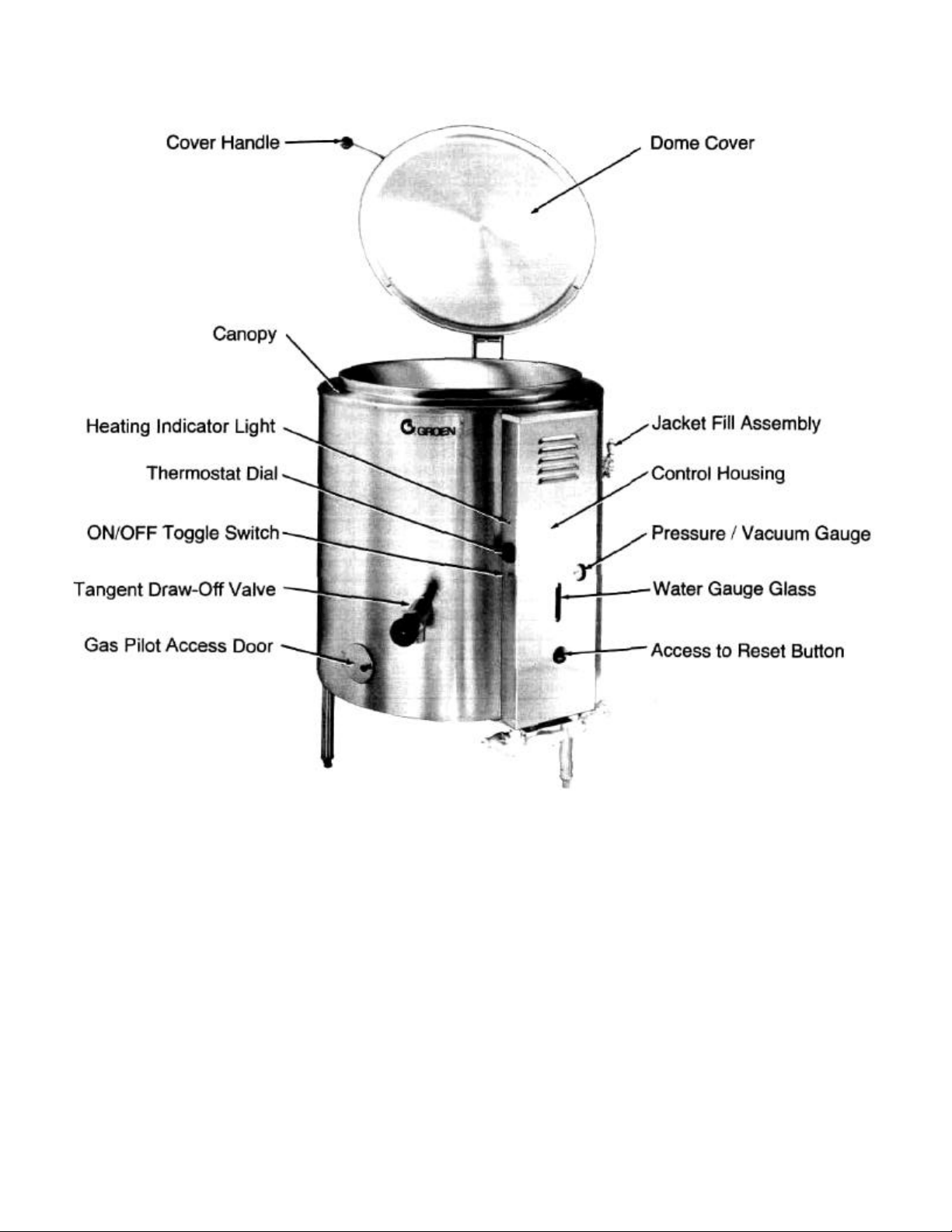
All exposed surfaces are stainless steel. An insulated canopy protects the kettle body, and a housing
encloses all the controls.
Three tubular legs support the unit. Bullet feet on the legs can be adjusted to level the kettle.
A one piece dome cover is hinged to the kettle. Covers for 60, 80, and 100 gallon kettles are supplied with
counterbalancing actuators to hold the covers in the fully open or closed position.
Controls used by the operator include the ON/OFF switch, to control electric power for the unit, and the
thermostat, to set the cooking temperature.
The automatic controls and a brief description are listed below.
Gas pressure regulator: Protects the unit from high pressure in the gas supply line
Automatic gas valves: Let gas into the burners at the proper time
Pressure limit switch: Closes the main automatic gas valve when steam pressure in
the jacket reaches 27 PSI and opens the valve when the
pressure drops to
22
PSI
Safety valve: Lets steam out of the jacket if the steam pressure gets too high
Low-water cutoff: Turns off the burner if the water level in the jacket gets too low
for safe operation
Instruments also are provided to show the operator what is happening inside the unit. These instruments
are:
Water gauge glass: Indicates whether there is enough water in the steam jacket
Pressure/vacuum gauge: Shows the steam pressure and whether too much air has got
into the jacket
Heating indicator light: Indicates that the kettle is being heated
The kettle body is welded into one piece and furnished with a rim reinforced by a rectangular bar. The interior
of the kettle is polished to a 180 emery grit finish, while the exterior is given a bright semi-deluxe finish. The
unit is ASME shop inspected and registered with the National Board for working pressures up to 30 PSI.
The standard 2 inch tangent draw-off is a 316 stainless steel, compression disc valve. A removable strainer
with 1/4 inch holes keeps pieces of product that are too large from going down into the drawoff.
The jacket is filled at the factory with water containing rust inhibitors. The kettle can operate at steam
pressures up to 30 PSI, which provide kettle temperatures of 150 to 270°F. This temperature range allows
the operator to use the kettle for warming, simmering, boiling, or braising.
For AH kettles, options include:
1. Larger (3 inch) draw-offs
2.
Plug-type draw-off valves (not NSF approved)
3. Solid disc strainer or strainer with 1/8 inch perforations
4. Electronic spark ignition
5.
Fill faucet
6. Automatic, metered water filler (Gallon Master)
7.
TRI-BC basket inserts
8. Kettle brush kit
9. Etch marks
10.
Flanged feet
2
Model AH/1
3
Equipment Description (cont'd)
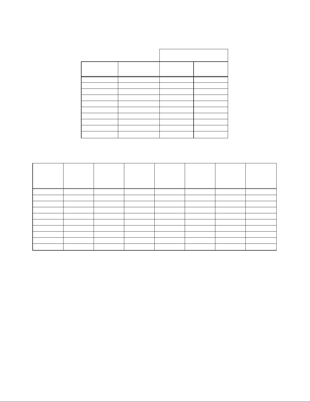
KETTLE CHARACTERISTICS
Firing rate,
BTU/hour
Model Ignition
Natural
gas
Propane
gas
AH/1-20 Pilot 85,000 85,000
AH/1-40
Pilot
100,000
85,000
AH/1-60
Pilot
145,000
145,000
AH/1-80
Pilot
145,000
145,000
AH/1-100
Pilot .
145,000
145,000
AH/1E-20
Spark
85,000
85,000
AH/1E-40
Spark
100,000
85,000
AH/1E-60
Spark
145,000
145,000
AH/1E-80
Spark
145,000
145,000
AH/1E-100 Spark 145,000 145,000
Dimensions
Model
Kettle
capacity,
gallons
Jacket
capacity,
gallons
Kettle
diame ter,
inches
Kettle
depth,
inches
Overall
width,
inches
Overall
front-to-
back,
inches
Rim
height,
nches
AH/1-20 20 4-1/2 20 18 36-3/4 39 40
AH/1-40
40
7
26
22
38-1/4
45
42
AH/1-60
60
9-1/2
30
25
41
49
49
AH/1-80
80
11-1/2
32
29
42-1/2
51
55-1/2
AH/1-100
100
11-1/2
32
35
42-1/2
51
61-1/2
AH/1E-20
20
4-1/2
20
18
36-3/4
39
40
AH/1E-40
40
7
26
22
38-1/4
45
42
AH/1E-60
60
9-1/2
30
25
41
49
49
AH/1E-80
80
11-1/2
32
29
42-1/2
51
55-1/2
AH/1E-100 100 11-1/2 32 35 42-1/2 51 61-1/2
Inspection & Unpacking
The unit will arrive completely assembled, wrapped in protective plastic on a heavy skid. Immediately upon
receipt, remove all protective plastic wrap form the unit, and inspect the unit for damage. Report any shipping
damage or an incorrect shipment to the delivery agent.
Write down the model number, serial number, and installation date of your unit, and file this information for
future reference. Space for these entries is provided at the top of the Service Log in this manual.
CAUTION: SHIPPING STRAPS ARE UNDER TENSION AND CAN SNAP BACK WHEN CUT.
CAUTION: UNIT WEIGHS 440 TO 1100 LB. (200 TO 500 KG). FOR SAFE HANDLING, INSTALLER
SHOULD OBTAIN HELP AS NEEDED, OR EMPLOY APPROPRIATE MATERIALS
HANDLING EQUIPMENT (SUCH AS A FORKLIFT, DOLLY, OR PALLET JACK) TO REMOVE
THE UNIT FROM THE SKID ANDMOVEIT TO THE PLACE OF INSTALLATION.
When installation is to begin, cut the straps holding the unit on the skid, and lift the unit straight up off the
skid.
4
Installation & Start-Up
A. Installation
The unit should be installed in a ventilated room for efficient performance. All items which may obstruct or
restrict the flow of air for combustion and ventilation must be removed. The area directly around the appliance
must be cleared of all combustible materials.
WARNING: INSTALLATION OF THE UNIT MUST BE DONE BY PERSONNEL QUALIFIED TO WORK WITH ELECTRICITY
AND PLUMBING. IMPROPER INSTALLATION CAN CAUSE INJURY TO PERSONNEL AND/OR DAMAGE TO
EQUIPMENT. UNIT MUST BE INSTALLED IN ACCORDANCE WITH ALL APPLICABLE CODES.
1. Installation requires connection with gas and electrical services. See items 8 to 14 for details.
2. To protect the unit from damage, leave it on the shipping pallet until the time of installation. When
installation is to begin, cut the straps holding the kettle, and hoist the kettle straight up off the skid.
NOTICE: To avoid damaging parts of the burner system underneath the kettle, LIFT THE
UNIT ONLY BY THE RING beneath the outer portion of the body.
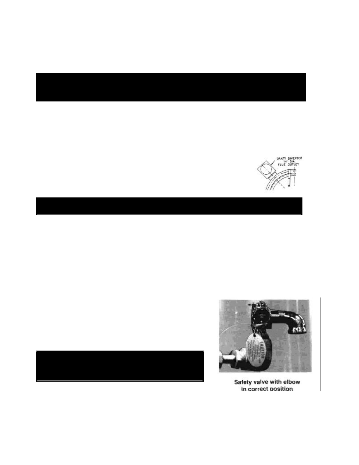
3. Install the unit with a minimum clearance to combustible and non-combustible construction of six (6)
inches at the sides and six (6) inches between the draft diverter and the
wall. Also leave enough room for cleaning, maintenance, and service.
4. The draft diverter shipped with the kettle is the correct height and shape to
give maximum performance. Install the draft diverter as shown on the
specification sheet (drawing D-6038). Do not change the diverter in any
way. Any mechanical, electrical, or gas type change must be
aDDroved bv the Groen Food Service Enaineerina Deoartment.
WARNING: DO NOT ATTACH THE UNIT TO A TYPE "B" VENT. FAILURE COULD RESULT IN FIRE OR
PROPERTY DAMAGE.
Install the unit under a ventilation hood, or vent the flue directly to a masonry chimney. Put a hood
at least several inches above the upper end of the draft diverter. Do not rest hood supports on the
diverter. If the kettle is installed under a ventilating hood, installation of the ventilating hood should
comply with local codes and/or ANSI/NFPA-96 Latest Edition. Also, local codes may require that
the kettle be electrically interlocked to shut off the gas supply and prevent the operation of the unit if
the exhaust fan is not operating or if the fire suppression system is activated. Failure to follow these
instructions can cause bodily injury and/or property damage.
5. To level the unit, adjust leg length by turning the bullet feet.
6. Make sure the water level is correct in the jacket, by confirming that the level is between the marks
on the gauge glass. If the water level is low, follow the instructions under "Jacket Filling" in the
"Maintenance" Section of this manual.
CAUTI0N: DO NOT CONNECT ANY PIPING TO THIS POP
SAFETY VALVE. IT MUST BE FREE TO VENT
STEAM AS NEEDED. ELBOW SHOULD POINT
DOWN TOWARD FLOOR. IMPROPER
INSTALLATION WILL VOID WARRANTY!
7. To protect personnel from steam coming out of the safety valve,
the open end of the elbow at the outlet must be directed down. If
it is not, turn the elbow to the correct position
DANGER: ELECTRICALLY GROUND THE UNIT AT THE
TERMINAL PROVIDED. FAILURE TO GROUND
UNIT COULD RESULT IN ELECTROCUTION
AND DEATH.
8. Provide 115 VAC, 60 HZ, 1 PH, 15 AMP electrical service. Use 1/2 inch waterproof conduit
and waterproof connections. Observe local codes and/or The National Electrical Code in
accordance with ANSI/NFPA 70 - latest edition. AN ELECTRICAL GROUND IS REQUIRED.
The electrical schematic is located on the inside of the service panel.
In Canada, provide electrical service in accordance with the Canadian Electrical Code, CSA C22.1 Part 1
and/or local codes.
5

Installation & Start-Up (cont'd)
9.
The internal gas lines of the unit were cleaned and closed off with a gas cock, before the unit was
shipped from the factory. Free all external gas lines of lint, dirt, metal chips, sealant, grease, oil,
and other contaminants, before you connect the lines to the kettle.
10.
Connect the gas cock of the kettle to the gas service main with 3/4 inch IPS line or approved
equivalent.
11.
Installation must conform with local codes, or in the absence of local codes, with the National Fuel
Gas Code, ANSI Z 223.1-1988 (or latest edition). The unit should be installed in an adequately
ventilated room with a provision for adequate air supply. The best ventilation will utilize a vent
hood and exhaust fan with no direct connection between the vent duct and the flue. Do NOT
obstruct the flue or vent duct after installation.
In Canada, the installation must conform to the CAN/CGA B149 Installation Codes for Gas
Burning Appliances and Equipment and/or local codes.
12.
Adequate space for proper service and operation is required. Do NOT block any air intake
spacings to the combustion chamber or obstruct the air flow by piling or stacking anything near
the kettle.
13.
After the kettle has been connected to the gas supply, all gas line joints must be checked for
leaks. DO NOT USE A FLAME TO CHECK FOR LEAKS. A thick soap solution or other suitable
leak detector should be employed.
14
For a unit on casters, complete connection to the gas supply with connectors that comply with the
standard for connectors for moveable gas appliances, ANSI Z21.69 — latest edition. Restrain
movement of the unit by attaching a cable or chain to the eyelet (provided at the back of the
frame) and anchoring the cable or chain to the wall or floor. Make the length and location of the
cable such that the unit cannot pull on the gas connection while the cable is connected.
15.
The appliance and its individual shutoff valve must be disconnected from the gas supply piping
system during any pressure testing of that system at test pressures in excess of 1/2 PSIG (3.48
kPa). The appliance must be isolated from the gas supply piping system by closing its individual
manual shutoff valve during any pressure testing of the gas supply piping system at test
pressures equal to or less than 1/2 PSIG (3.48 kPa).
16.
Check the following points to confirm that your AH kettle has been installed properly.
a. Enough room between the kettle and nearby objects for cleaning and service.
b. Minimum clearance of 6 inches from sides and 6 inches from draft diverter.
c. Unit vented to a hood or chimney.
d. Kettle level.
e. Correct amount of water in the jacket.
f. Safety valve outlet pointed down.
g. Connected with a waterproof, 115 volt, 15 amp supply of electric power in accordance with
electrical codes.
h. Gas lines cleaned before connection.
i. Gas connected with 3/4 inch pipe or equivalent.
j. Gas line joints checked for leaks.
k. No obstruction to air supply or venting.
B. Initial Start
-
Up
After the kettle has been installed, the installer should test to ensure that the unit is operating correctly.
1.
Remove all literature and packing materials from the inside and outside of the unit. Clean out any
material that might clog or damage the tangent draw-off valve (TDO).
2.
Close the TDO, then put water into the kettle until the water is about 6 inches deep. Test operation
of the TDO by opening it all the way, then closing it before all the water runs out.
3.
Make sure the supplies of gas and electric power are on.
4.
Following "To Start Kettle" instructions in the "Operation" section of this manual, begin heating the
water at the highest thermostat setting. The heating indicator light should come on as soon as you
turn up the thermostat dial, and heating should continue until the water boils.
5.
To turn off the unit, follow "To Turn Off Kettle" instructions in the "Operation" section.
If the kettle functions as described above, it is ready for use. If it does not, contact your area Groen
representative.
6
Operation
CAUTION: BE SURE ALL OPERATORS READ, UNDERSTAND AND FOLLOW THE
OPERATING INSTRUCTIONS, CAUTIONS AND SAFETY INSTRUCTIONS
CONTAINED IN THIS MANUAL.
A. Controls
The operator controls for the kettle are:
1. Main gas cock, which controls the supply of gas from the main to the unit.
2. ON/OFF (toggle) switch. This switch controls the supply of electrical power to the control circuits.
3. Thermostat dial, which turns the thermostat on or off and sets the operating temperature of the
kettle.
4. Reset button, used in lighting the pilot burner (on standing pilot model only).
Refer to the photograph in the "Equipment Description" section of this manual for the location of
controls and other features.
B. Operating Procedure
WARNING: KEEP AREA AROUND KETTLE FREE AND
CLEAR OF ALL COMBUSTIBLE
MATERIALS.
1. To Start Kettle
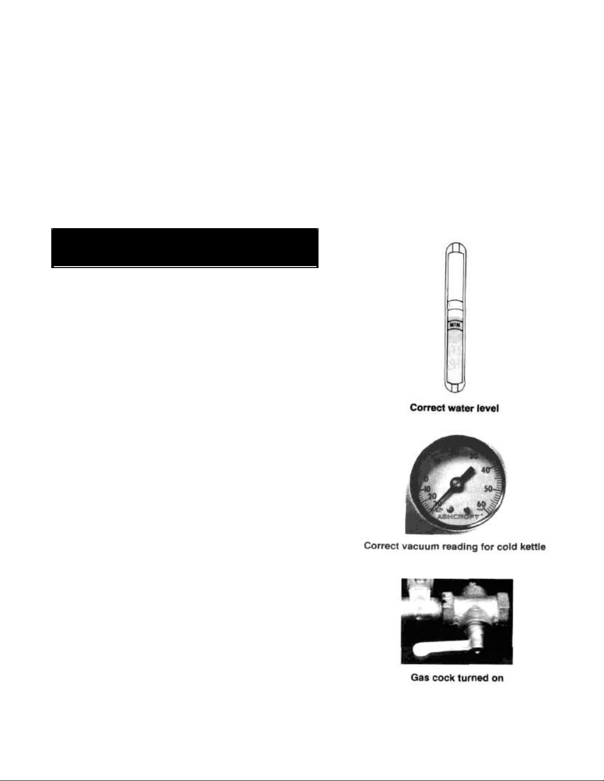
a. CHECK THE WATER LEVEL IN THE JACKET EVERY
DAY. The level must be between the lines on the
gauge glass. If the level is low, see "Jacket Filling" in
the "Preventive Maintenance" section of this manual.
b. While the kettle is cold, check the pressure gauge. If
the gauge does not show 20 or more inches of vacuum
(that is, a reading of 20 to 30 below 0), see "Jacket
Vacuum" in the "Preventive Maintenance" section of
this manual.
c. Make sure the strainer is covering the outlet to the
draw-off at the bottom of the kettle.
d. Set both the toggle (ON/OFF) switch and the
thermostat dial to "OFF".
e. If the unit has just been turned off, allow 5 minutes for
unburned gas to clear out, before you turn the kettle on
again.
f. Turn the gas cock ON (handle lined up with the gas
pipe), if it is not already on.
g. If you are using Model AH/1 E with electronic spark
ignition, or if you are using a Model AH/1 unit with the
pilot burner already lit, all you must do to start heating
the kettle is:
(1) Press the ON/OFF switch to "ON".
(2) Turn the thermostat dial to the desired setting.
h. If you must light the pilot burner in a Model AH/1, look
through the access hole in the cover of the control
housing to see which kind of pilot system is in your
unit. If there is a red reset button on top of the gas
control, you have a Basotrol pilot system. If you see an
"ON/PILOT/OFF" knob, you have a Honeywell pilot
system.
7
MAX
niiT

Operation (cont'd)
i. Light the pilot burner by the procedure that applies to your unit.
(1)
With Basotrol standing pilot ignition system:
(a) Locate the red reset button on the automatic gas valve inside the control
housing. You can reach the button through the hole below the pressure gauge.
(b)
Hold a flame to the pilot burner and press down the reset button to start the flow
of gas. Continue to hold the reset button down
for
60
seconds after the pilot
burner is lit.
(c) Release the button. The pilot burner should stay lit.
(2)
With Honeywell pilot ignition system:
(a) To reach the "ON/PILOT/OFF" knob, remove the cover of the control housing.
(b) Set the knob to "PI LOT".
(c) Hold a flame to the pilot burner and press down the knob to start the flow of
gas. Continue to hold the knob down for 60 seconds after the pilot burner is lit.
(d) Release the knob. The pilot should stay lit.
(e) Set the knob to "ON". Then replace the cover of the control housing.
(3)
For all units, if pilot requires relighting:
(a) Set both the ON/OFF switch and the thermostat dial to their "OFF" positions.
(b) Wait 5 minutes.
(c) Light the pilot by the appropriate procedure above.
j. To light the main burner and start heating the kettle, after the pilot burner is lit:
(1)
Press the ON/OFF switch to "ON".
(2)
Turn the thermostat dial to the desired setting.
CAUTION:
DO NOT OVER FIL
L THE KETTLE WHEN COOKING, HOLDING OR
CLEANING. KEEP LIQUIDS A MINIMUM OF 2-3" (5-8 CM) BELOW THE
KETTLE BODY RIM TO ALLOW CLEARANCE FOR STIRRING, BOILING
PRODUCT AND SAFE TRANSFER.
CAUTION: KEEP FLOORS IN FRONT OF KETTLE WORK AREA CLEAN AND DRY. IF
SPILLS OCCUR, CLEAN IMMEDIATELY TO AVOID THE DANGER OF SLIPS
OR FALLS.
2.
To Turn Off Kettle.
a. Turn the thermostat dial to "OFF".
b. Press the ON/OFF switch to "OFF".
c. Before the unit is serviced, or if it will be off for a week or more:
(1) Set the thermostat and ON/OFF switch at "OFF".
(2) Turn the main gas cock OFF (handle at right angles to the gas pipe).
(3) Cut off electric power for the unit at the circuit breaker or fuse box.
3.
If Electric Power Fails
a. Do not attempt to operate the unit. The main burner cannot be lit until the power comes back
on.
b. When power is restored, follow the instructions under "To Start Kettle" above.
4.
To Relight Kettle
Close the main supply gas cock, then follow the instructions under "To Start Kettle" above.
8
 Loading...