


IMPORTANT INFORMATION• KEEP FOR OPERATOR• IMPORTANT INFORMATION
OPERATOR MANUAL |
OM-HH |
Part Number 121034 |
DOMESTIC |
MODEL: HH/4 &HH/4/E |
|
Steam Jacketed Kettles |
|
Self-Contained
Natural Gas heated
Floor mounted
Stationary
THIS MANUAL MUST BE RETAINED FOR FUTURE REFERENCE. READ, UNDERSTAND AND FOLLOW THE INSTRUCTIONS AND WARNINGS CONTAINED IN THIS MANUAL.
WARNING
DO NOT STORE OR USE GASOLINE OR OTHER FLAMMABLE VAPORS AND LIQUIDS IN THE VICINITY OF THIS OR ANY OTHER APPLIANCE.
POST IN A PROMINENT LOCATION
INSTRUCTIONS TO BE FOLLOWED IN THE EVEN USER SMELLS GAS. THIS INFORMATION SHALL BE OBTAINED BY CONSULTING YOUR LOCAL GAS SUPPLIER. AS A MINIMUM, TURN OFF THE GAS AND CALL YOUR GAS COMPANY AND YOUR AUTHORIZED
SERVICE AGENT. EVACUATE ALL PERSONNEL FROM THE AREA. WARNING
IMPROPER INSTALLATION, ADJUSTMENT, ALTERATION, SERVICE OR MAINTENANCE CAN CAUSE PROPERTY DAMAGE, INJURY OR DEATH. READ THE INSTALLATION, OPERATING AND MAINTENANCE INSTRUCTIONS THOROUGHLY BEFORE INSTALLING OR SERVICING THIS EQUIPMENT.
Information contained in this document is known to be current and accurate at the time of printing/creation. Unified Brands recommends referencing our product line websites, unifiedbrands.net, for the most updated product information and specifications.

OM-HH
IMPORTANT — READ FIRST — IMPORTANT
WARNING INSTALLATION OF THE UNIT MUST BE DONE BY PERSONNEL QUALIFIED TO WORK WITH ELECTRICITY AND PLUMBING. IMPROPER INSTALLATION CAN CAUSE INJURY TO PERSONNEL AND/OR DAMAGE TO EQUIPMENT. UNIT MUST BE INSTALLED IN ACCORDANCE WITH ALL APPLICABLE CODES.
CAUTION TO AVOID DAMAGING PARTS OF THE BURNER SYSTEM UNDERNEATH THE KETTLE, LIFT THE UNIT ONLY BY THE RING BENEATH THE OUTER PORTION OF THE BODY.
WARNING DO NOT ATTACH THE UNIT TO A TYPE “B” VENT. FAILURE COULD RESULT IN FIRE
|
OR PROPERTY DAMAGE. |
WARNING DO NOT CONNECT ANY PIPING TO THE SAFETY VALVE. THE VALVE MUST BE FREE |
|
|
TO VENT STEAM AS NEEDED. ELBOW, ATTACHED TO THE SAFETY VALVE, SHOULD |
|
POINT DOWN TOWARD THE FLOOR. IMPROPER INSTALLATION WILL VOID THE |
|
WARRANTY! |
DANGER |
ELECTRICALLY GROUND THE UNIT AT THE TERMINAL PROVIDED. FAILURE TO |
|
GROUND THE UNIT COULD RESULT IN ELECTROCUTION AND DEATH. |
CAUTION |
BE SURE ALL OPERATORS READ, UNDERSTAND AND FOLLOW THE OPERATING |
|
INSTRUCTIONS, CAUTIONS AND SAFETY INSTRUCTIONS CONTAINED IN THIS |
|
MANUAL. |
CAUTION |
DO NOT OVERFILL THE KETTLE WHEN COOKING, HOLDING OR CLEANING. KEEP |
|
LIQUIDS A MINIMUM OF 2-3” (5-8 CM) BELOW THE KETTLE BODY RIM TO ALLOW |
|
CLEARANCE FOR STIRRING, BOILING PRODUCT AND SAFE TRANSFER. |
CAUTION |
KEEP FLOORS IN FRONT OF KETTLE WORK AREA CLEAN AND DRY. IF SPILLS |
|
OCCUR, CLEAN IMMEDIATELY TO AVOID DANGER OF SLIPS OR FALLS. |
WARNING KEEP WATER AND SOLUTIONS OUT OF CONTROLS AND BURNERS. NEVER SPRAY |
|
|
OR HOSE CONTROL CONSOLE, ELECTRICAL CONNECTIONS, ETC. |
CAUTION |
MOST CLEANERS ARE HARMFUL TO THE SKIN, EYES, MUCOUS MEMBRANES AND |
|
CLOTHING. PRECAUTIONS SHOULD BE TAKEN TO WEAR RUBBER GLOVES, |
|
GOGGLES OR FACE SHIELD AND PROTECTIVE CLOTHING. CAREFULLY READ THE |
|
WARNINGS AND FOLLOW THE DIRECTIONS ON THE LABEL OF THE CLEANER TO BE |
|
USED. |
Important |
Do not mix the parts of different tangent draw-off valve assemblies during washing. The |
|
parts are not interchangeable. |
NOTICE |
NEVER leave a sanitizer in contact with stainless steel surfaces LONGER THAN 10 |
|
minutes. Longer contact can cause corrosion. |
WARNING FAILURE TO PERIODICALLY CHECK SAFETY VALVE OPERATION COULD RESULT IN PERSONAL INJURY AND/OR DAMAGE TO EQUIPMENT.
WARNING WHEN TESTING, AVOID ANY EXPOSURE TO THE STEAM BLOWING OUT OF THE SAFETY VALVE. DIRECT CONTACT COULD RESULT IN SEVERE BURNS.
WARNING TO AVOID INJURY, READ AND FOLLOW ALL PRECAUTIONS STATED ON THE LABEL
|
OF THE WATER TREATMENT COMPOUND. |
WARNING BEFORE REPLACING ANY PARTS, DISCONNECT THE UNIT FROM THE ELECTRIC |
|
|
POWER SUPPLY AND CLOSE THE MAIN GAS COCK. ALLOW FIVE MINUTES FOR |
|
UNBURNED GAS TO VENT. |
CAUTION |
USE OF ANY REPLACEMENT PARTS OTHER THAN THOSE SUPPLIED BY GROEN OR |
|
THEIR AUTHORIZED DISTRIBUTOR CAN CAUSE INJURY TO THE OPERATOR AND |
|
DAMAGE TO THE EQUIPMENT AND WILL VOID ALL WARRANTIES. |
Important |
Service performed by other than factory authorized personnel will void all warranties. |
WARNING KEEP AREA AROUND KETTLE FREE AND CLEAR OF COMBUSTIBLE MATERIALS. FAILURE TO DO SO COULD RESULT IN FIRE AND PROPERTY DAMAGE.
2
OM-HH
Table of Contents
IMPORTANT OPERATOR WARNINGS . . . . . . . . . . . . . . . . . . . . . . . . . . . . . . . . . . . . 2 EQUIPMENT DESCRIPTION . . . . . . . . . . . . . . . . . . . . . . . . . . . . . . . . . . . . . . . . . . . . . 4 INSPECTION & UNPACKING . . . . . . . . . . . . . . . . . . . . . . . . . . . . . . . . . . . . . . . . . . . . 6 INSTALLATION . . . . . . . . . . . . . . . . . . . . . . . . . . . . . . . . . . . . . . . . . . . . . . . . . . . . . . . 7 INITIAL START-UP . . . . . . . . . . . . . . . . . . . . . . . . . . . . . . . . . . . . . . . . . . . . . . . . . . . . 8 OPERATION . . . . . . . . . . . . . . . . . . . . . . . . . . . . . . . . . . . . . . . . . . . . . . . . . . . . . . . . . 9 SEQUENCE OF OPERATION . . . . . . . . . . . . . . . . . . . . . . . . . . . . . . . . . . . . . . . . . . . 11 MAINTENANCE . . . . . . . . . . . . . . . . . . . . . . . . . . . . . . . . . . . . . . . . . . . . . . . . . . . . . 12 CLEANING . . . . . . . . . . . . . . . . . . . . . . . . . . . . . . . . . . . . . . . . . . . . . . . . . . . . . . . . . . 14 TROUBLESHOOTING . . . . . . . . . . . . . . . . . . . . . . . . . . . . . . . . . . . . . . . . . . . . . . . . . 15 PARTS LISTS . . . . . . . . . . . . . . . . . . . . . . . . . . . . . . . . . . . . . . . . . . . . . . . . . . . . . . . . 18 SCHEMATICS . . . . . . . . . . . . . . . . . . . . . . . . . . . . . . . . . . . . . . . . . . . . . . . . . . . . . . . 20 REFERENCES . . . . . . . . . . . . . . . . . . . . . . . . . . . . . . . . . . . . . . . . . . . . . . . . . . . . . . . 22 MAINTENANCE LOG . . . . . . . . . . . . . . . . . . . . . . . . . . . . . . . . . . . . . . . . . . . . . . . . . . 23 WARRANTY . . . . . . . . . . . . . . . . . . . . . . . . . . . . . . . . . . . . . . . . . . . . . . . . . . . . . . . . . 24
References |
|
KLENZADE SALES CENTER ECOLAB. Inc. |
NATIONAL SANITATION FOUNDATION |
370 Wabasha |
3475 Plymouth Rd. |
St. Paul, Minnesota 55102 |
Ann Arbor, Michigan 48106 |
800/352-5326 or 612/293-2233 |
UNDERWRITERS LABORATORIES, INC. |
|
|
NATIONAL FIRE PROTECTION ASSOCIATION |
333 Pfingsten Road |
60 Battery March Park |
Northbrook, Illinois 60062 |
Quincy, Massachusetts 02269 |
ZEP MANUFACTURING CO. |
|
|
NFPA/70 - The National Electrical Code |
1310-T Seaboard Industrial Blvd. |
|
Atlanta, Georgia 30318 |
ECONOMICS LABORATORY, INC.
St. Paul, Minnesota 55102
3
OM-HH
Equipment Description
Groen Models HH/4 and HH/4E steam kettles are stainless steel, floor mounted 40 gallon kettles with a self-contained steam source heated by gas. A closed steam jacket covers the lower b of the kettle. Heat from gas flames boils water in the jacket to produce steam under pressure. To ignite the flames, Model HH/4 has a continuously burning pilot flame, called the standing pilot, and Model HH/4E has electronic spark ignition.
The kettles are of the stationary (nontilting) type. Liquids can be removed from the kettle through the tangent draw-off valve (a “product faucet”) at the front of the kettle.
All exposed surfaces are stainless steel. An insulated canopy protects the kettle body, and a housing encloses all the controls. A one piece dome cover is hinged to the kettle.
Three tubular legs support the unit. Bullet feet on the legs can be adjusted to level the kettle.
Controls used by the operator include the ON/OFF switch, which controls electric power for the unit, and the thermostat, which sets the cooking temperature.
Instruments are provided to show what is happening inside the unit:
•Water gauge glass: shows the level of water within the steam jacket
•Pressure/vacuum gauge: shows the steam pressure and if there is air in the jacket
•Indicator lamp: Lights when the kettle is being heated
Automatic controls within the unit:
•Gas Pressure Regulator: Adjusts gas pressure up to 14" W.C.
•Pressure Limit Switch: Turns the main burner off when steam in the jacket reaches its highest operating pressure.
•Low-water cutoff: Turns off the burner if water level in the jacket gets too low for safe operation.
•Safety valve: Releases steam if jacket pressure gets too high
The 40 gallon kettle body is welded into one piece and furnished with a rim reinforced by a rectangular bar. The unit is ASME shop inspected and registered with the National Board for working pressures up to 30 PSI.
The standard 2 inch tangent draw-off has a removable strainer with ¼ inch holes which keep pieces of product that are too large from going down into the draw-off.
The jacket is filled at the factory with water containing rust inhibitors. The kettle can operate at steam pressures up to 30 PSI, which provide kettle temperatures of 150 to approximately 270°F (56 to 132ºC). This temperature range allows the operator to use the kettle for warming, simmering, boiling, or braising.
Optional equipment for the HH/4 kettles includes:
•Three inch draw-off valve
•c” perforated or solid disc strainer
•Basket inserts (TRI-BC)
•Water fill faucets
•Automatic water filler
•Kettle brush kit
•316 stainless steel liner
4

OM-HH
KETTLE CHARACTERISTICS
Model |
HH/4 |
HH/4/E |
|
|
|
Ignition |
Pilot |
Spark |
|
|
|
Capacity, gallons (liters) |
40 (150) |
40 (150) |
|
|
|
Rim Height, inches (mm) |
38 (960) |
38 (960) |
|
|
|
Depth, inches (mm) |
22 (560) |
22 (560) |
|
|
|
Diameter, inches (mm) |
26 (660) |
26 (660) |
|
|
|
Overall front-to back, inches (mm) |
40½ (1030) |
40½ (1030) |
|
|
|
Firing Rate, BTU/hour |
129,000 |
129,000 |
|
|
|
Energy into product, BTU/hour |
82,500 |
82,500 |
|
|
|
5

OM-HH
Inspection & Unpacking
The unit will arrive in a heavy shipping carton and will be banded to a skid. Immediately upon receipt, inspect the carton carefully for exterior damage.
CAUTION
SHIPPING STRAPS ARE UNDER TENSION AND CAN SNAP BACK WHEN CUT. TAKE CARE TO AVOID PERSONAL INJURY OR DAMAGE TO THE UNIT BY STAPLES LEFT IN THE WALLS OF THE CARTON.
Carefully cut any restraining straps around the carton and detach the sides of the box from the skid. Pull the carton up off the unit.
Thoroughly inspect for concealed damage. Report any shipping damage or incorrect shipments to the delivery agent. Write down the model number, serial number, and installation date, and retain this information for future reference.
Space for these entries is provided at the top of the Service Log at the back of this manual. Keep the manual available for operators to use.
CAUTION
THIS UNIT IS VERY HEAVY. INSTALLER SHOULD OBTAIN HELP AS NEEDED TO LIFT THIS WEIGHT SAFELY.
When installation is to begin, carefully cut any straps which hold the unit on the skid. Lift the unit straight up off the skid. Examine packing materials to be sure that loose parts are not discarded with the materials.
The tangent draw-off valve is usually shipped unassembled. Once the kettle is unpacked, it is easily attached, as shown below. The large nut which attaches the valve to the kettle should only be hand tightened.
The kettle will be banded to a skid, inside a heavy carton.
Assemble and attach the tangent draw-off valve after the kettle is unpacked.
6
OM-HH
Installation
A. Installation
The unit should be installed in a ventilated room for efficient performance. Items which obstruct or restrict the flow of air for combustion and ventilation must be removed. The area around the appliance must be free of combustible materials.
WARNING
THE KETTLE MUST BE INSTALLED BY PERSONNEL QUALIFIED TO WORK WITH ELECTRICITY. IMPROPER INSTALLATION CAN RESULT IN INJURY TO PERSONNEL AND/OR DAMAGE TO EQUIPMENT.
1.Installation requires connection with gas and electrical services. See items 8 to 14 for details.
2.To protect the unit from damage, leave it on the shipping pallet until installation. When installation is to begin, cut the straps holding the kettle, and hoist it straight up off the skid.
NOTICE:To avoid damaging parts of the burner system underneath the kettle, LIFT THE UNIT ONLY BY THE RING beneath the outer edge of the body.
3.Install the unit with a minimum clearance to combustible and non-combustible construction of six inches at the sides and six inches between the draft diverter and the wall. Also leave enough room for cleaning, maintenance, and service.
4.The draft diverter (flue) shipped with the kettle is the correct height and shape for maximum performance. Slide the diverter onto the flue collar at the back of the kettle and secure it with the two sheet metal screws provided.. Do not change the diverter in any way.
Any mechanical, electrical, or gas type change must be approved by the Groen Food Service Engineering Department.
WARNING
DO NOT ATTACH THE UNIT TO A TYPE “B” VENT. FAILURE COULD RESULT IN A FIRE AND/OR PROPERTY DAMAGE.
Install the unit under a ventilation hood, or vent the flue directly to a masonry chimney. Put a hood at least several inches above the upper end of the draft diverter (flue). Do not
rest hood supports on the diverter. The ventilating hood should comply with local codes and/or ANSI/NFPA-96 Latest Edition. Local codes may also require that the kettle be electrically interlocked to shut off the gas supply and prevent operation if the exhaust fan is not operating or if the fire suppression system is activated.
5.Level the unit by turning the bullet feet.
6.Confirm that the jacket water level is between the marks on the gauge glass. If the water is low, follow the instructions in “Jacket Filling” in the “Maintenance” Section of this manual. Do not connect the unit to a water supply.
CAUTION
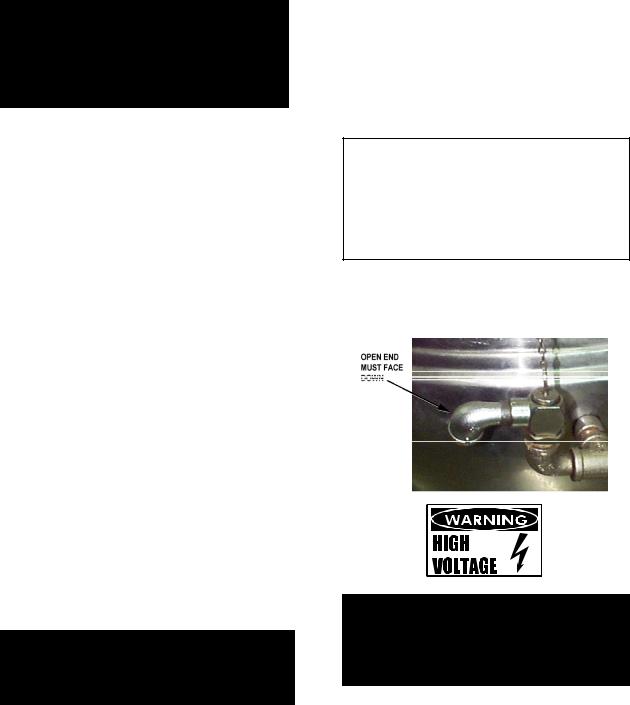
DO NOT CONNECT ANY PIPING TO THE SAFETY VALVE. IT MUST BE FREE TO VENT STEAM AS NEEDED. ELBOW SHOULD POINT DOWN TOWARD FLOOR. IMPROPER INSTALLATION WILL VOID WARRANTY!
7.The open end of the elbow at the safety valve outlet must be directed down. If it is not, turn the elbow to the correct position.
WARNING
ELECTRICALLY GROUND THE UNIT AT THE TERMINAL PROVIDED. FAILURE TO GROUND UNIT COULD RESULT IN ELECTROCUTION AND DEATH.
8.Provide 115 VAC, 60 HZ, 1 PH, 15 AMP electrical service. Use ½ inch waterproof conduit and waterproof connections. Observe local codes and/or The National Electrical Code in accordance with ANSI/NFPA 70 - latest edition. An electrical ground is
7
OM-HH
required. The electrical schematic is on the inside of the service panel and in this manual.
9.Internal gas lines were cleaned and closed off with a gas valve before the unit was shipped. Free external gas lines of lint, dirt, metal chips, sealant, grease, oil, or other contaminants before connecting them to the kettle.
10.Connect the kettle gas valve to the gas service main with ¾ inch IPS line or an approved equivalent.
11.Installation must conform with local codes and with the National Fuel Gas Code, ANSI Z 223.1-1988 (or latest edition). Install the unit in an adequately ventilated room and ensure an adequate air supply. The best ventilation will use a vent hood and exhaust fan with no direct connection between the vent duct and the flue. Do NOT obstruct the flue or vent duct after installation.
12.Adequate space for proper service and operation is required. Do NOT block any air intake spacings to the combustion chamber or obstruct the air flow by piling or stacking anything near the kettle.
13. .After the kettle has been connected to the gas supply, check each gas line joint for leaks. DO NOT USE A FLAME TO CHECK FOR LEAKS. A thick soap solution or other leak detector should be employed.
14.The appliance and its individual shutoff valve must be disconnected from the gas supply piping system during any pressure testing at test pressures in excess of ½ PSI (3.48 kPa). The unit must be isolated from the gas supply piping system by closing its manual shutoff valve during any pressure testing of the gas piping system at pressures equal to or less than ½ PSI (3.48 kPa).
15.Check the following points to confirm that your HH kettle has been installed properly.
a.Sufficient room between the kettle and nearby objects for cleaning and service.
b.Minimum clearance of six inches from the kettle’s sides and draft diverter.
c.Unit vented to a hood or chimney.
d.Kettle is level.
e.Correct amount of water in the jacket.
f.Safety valve outlet is pointed down.
g.Connected with a waterproof, 115 volt, 15 amp supply of electric power and grounded in accordance with electrical codes.
h.Natural gas lines cleaned before connection.
i.Gas connected with ¾ inch pipe.
j.Gas line joints checked for leaks.
k.No obstruction to air supply or venting
B. Initial Start-Up.
After installation, the installer should test the kettle to ensure that it is operating correctly.
1.Remove all literature and packing materials from the inside and outside of the unit. Clean out any material that might clog or damage the tangent draw-off valve.
2.Close the draw-off valve, and put water into the kettle to a depth of about six inches. Test draw-off operation by opening it all the way, then closing it before all the water runs out.
3.Make sure the supplies of gas and electric power are on.
4.Following “To Start Kettle” instructions on Page nine of this manual, begin heating the water at the highest thermostat setting. The heating indicator light should come on as soon as you turn up the thermostat dial, and heating should continue until the water boils.
5.To turn off the unit, follow “To Turn Off Kettle” instructions on page 10.
If the kettle functions as described, it is ready for use. If it does not, contact your area Groen Authorized Service Representative.
8
 Loading...