


SSB-3G, (2)SSB-5G Operation Manual")
IMPORTANT INFORMATION I KEEP FOR OPERATOR I IMPORTANT INFORMATION
operator manual |
om-ssb-3g/5g/10gf |
part number 145144 rev. D |
Domestic |
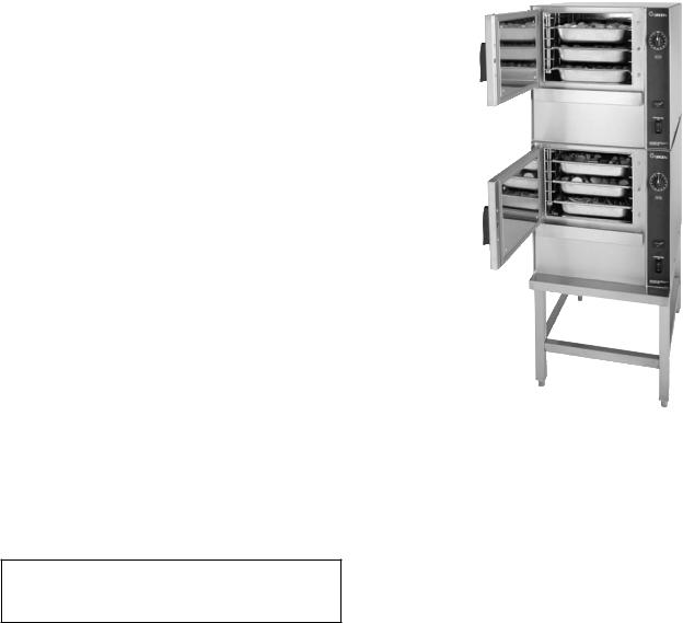
moDels: ssb-3g/5g/10gf, (2)ssb-3g/5g/10gf smartsteam™
boilerless steamer
self-contained gas-Heated
capacity` 3, 5 or 10 pans steamer pans [per cavity]
(12” x 20” x 2 1/2”)
Use for steamers with Serial Numbers ending with “MSD”
tHis manual must be retaineD for future reference. reaD, unDerstanD anD folloW tHe instructions anD Warnings containeD in tHis manual.
for Your safetY
Do not store or use gasoline or otHer flammable Vapors anD liQuiDs in tHe VicinitY of tHis or anY otHer appliance.
post in a prominent location
instructions to be folloWeD in tHe eVent user smells gas. tHis information sHall be obtaineD bY consulting Your local gas supplier. at a minimum, turn off gas anD call Your gas companY anD Your autHoriZeD serVice agent. eVacuate all personnel from tHe area.
Warning
improper installation, aDJustment, alteration, serVice or maintenance can cause propertY Damage, inJurY or DeatH. reaD tHe installation, operating anD maintenance instructions tHorougHlY before installing or serVicing tHis eQuipment.
Information contained in this document is known to be current and accurate at the time of printing/creation. Unified Brands recommends referencing our product line websites, unifiedbrands.net, for the most updated product information and specifications.

om-ssb-3g/5g/10gf
important –– reaD first –– important
Warning: tHe unit must be installeD bY personnel QualifieD to WorK WitH electricitY anD plumbing. improper installation can cause inJurY to personnel anD/or Damage to tHe eQuipment. tHe unit must be installeD in accorDance WitH applicable coDes.
caution: sHipping straps are unDer tension anD can snap bacK WHen cut.
caution: Do not install tHe unit in anY WaY WHicH Will blocK tHe rear Vents, or WitHin 2 incHes of a Heat source sucH as a braising pan, Deep frYer, cHar broiler or Kettle.
caution: leVel tHe unit front to bacK, or pitcH it sligHtlY to tHe rear, to aVoiD Drainage problems.
Warning: folloW tHe Wiring Diagram eXactlY WHen connecting a unit to aVoiD Damage or inJurY. Wiring Diagram is locateD on tHe insiDe of tHe rigHt panel.
caution: Do not use plastic pipe. Drain must be rateD for boiling Water.
Warning: Do not connect tHe Drain DirectlY to a builDing Drain.
Warning: blocKing tHe Drain is HaZarDous.
important: improper Drain connection Will VoiD WarrantY.
important: Do not alloW anY Water traps in tHe line. a trap can cause pressure to builD up
|
insiDe tHe caVitY During steaming, WHicH Will maKe tHe Door gasKet leaK. |
Warning: |
WHen You open tHe Door, staY aWaY from steam coming out of tHe unit. |
|
steam can cause burns. |
Warning: |
before cleaning tHe outsiDe of tHe steamer, Disconnect tHe electric |
|
poWer supplY. Keep Water anD cleaning solutions out of controls anD |
|
electrical components. neVer Hose or steam clean anY part of tHe unit. |
Warning: |
alloW cooKing cHamber to cool completelY before cleaning. |
Warning: |
use milD cleaning agents onlY. carefullY reaD tHe Warnings anD folloW |
|
tHe Directions on tHe label of eacH cleaning agent. use safetY glasses |
|
anD rubber gloVes as recommenDeD bY cleaning agent manufacturer. |
Warning: |
Do not put HanDs or tools into tHe cooKing cHamber until tHe fan Has |
|
stoppeD turning. |
Warning: |
Do not operate tHe unit un less tHe remoVable rigHt siDe panel Has been |
|
returneD to its proper location. |
notice: |
Do not use a cleaning agent tHat contains anY sulfamic aciD, or anY |
|
cHloriDe, incluDing HYDrocHloric aciD. if tHe cHloriDe content of anY |
|
proDuct is unclear, consult tHe manufacturer. Do not use a cleaning or |
|
Deliming agent tHat contains more tHan 30% pHospHoric aciD. |
notice: |
Do not use anY Degreaser tHat contains potassium HYDroXiDe or soDium |
|
HYDroXiDe or tHat is alKaline. |
Warning: |
use of anY replacement parts otHer tHan tHose supplieD bY groen or tHeir |
|
autHoriZeD Distributor VoiDs all Warranties anD can result in boDilY |
|
inJurY to tHe operator anD Damage tHe eQuipment. serVice bY otHer tHan |
|
factorY-autHoriZeD personnel Will VoiD all Warranties. |
Warning: |
HigH Voltage eXists insiDe control compartments. Disconnect from brancH |
|
circuit before serVicing. failure to Do so can result in inJurY or DeatH. |
|
om-ssb-3g/5g/10gf |
|
table of contents |
operator Warnings......................................................................................................................................... |
2 |
references......................................................................................................................................................... |
3 |
eQuipment Description................................................................................................................................... |
4 |
inspection anD unpacKing ............................................................................................................................ |
4 |
installation anD startup ............................................................................................................................. |
5 |
operation ............................................................................................................................................................ |
9 |
cleaning............................................................................................................................................................. |
11 |
maintenance..................................................................................................................................................... |
13 |
troublesHooting........................................................................................................................................... |
13 |
serVice log....................................................................................................................................................... |
15 |
WarrantY protection .................................................................................................................................. |
17 |
|
references |
unDerWriters laboratories, inc. |
national fire protection association |
333 Pingsten Road |
60 Batterymarch Park |
Northbrook, Illinois 60062 |
Quincy, Massachusetts 02269 |
nfpa/70 The National Electrical Code |
NFPA/ 54 The National Fuel Gas Code |
national sanitation founDation |
|
3475 Plymouth Road |
|
Ann Arbor, Michigan 48106 |
|
om-ssb-3g/5g/10gf
equipment Description
Your Groen SSB- G/5G/10G or ( )SSG- G/5G/ 10G Smartsteam Boilerless Steamer is designed to give years of service. It has a stainless steel cavity (cooking chamber) which is served by an gas-heated atmospheric steam generating reservoir. A powerful
blower circulates the steam in the cavity to increase heating eficiency.
Each cavity holds up to three, ive or ten steam table pans (1 ” x 0” x 1/ ” deep) as shown below.
SSB |
|
|
|
|
Steamer |
|
|
|
|
|
1 x 0 x -1/ |
1 x 0 x |
1 x 18 |
18 x 6 |
|
(steamer) |
(steamer) |
(half size |
(bake) |
|
|
|
bake) |
|
|
|
|
|
|
SSB- G |
|
|
0 |
0 |
( )SSB- G |
6 |
|
0 |
0 |
SSB-5G |
5 |
|
0 |
0 |
( )SSB-5G |
10 |
6 |
0 |
0 |
SSB-10G |
10 |
6 |
0 |
10 |
( )SSB-10G |
0 |
1 |
0 |
0 |
|
|
|
|
|
An 18-guage stainless steel case encloses the cavity, the steam generating reservoir and the control
compartment that houses electrical components.
Door hinges are ield-reversible (the door may be set to open from the left or right). Operating controls are on the front panel.
The SSB- G/5G/10G steamers are equipped with electronic controls. These units are readily identiied
by their unique control panels. Steamer function is controlled by touch pad controls and a rotary timer.
The drain system on all models includes a spray condenser, which cools drain water.
Inspection and Unpacking
Your Groen SmartSteam Boilerless Steamer will be delivered completely assembled in a heavy shipping carton strapped to a skid. On receipt, inspect carton carefully for exterior damage.
caution
sHipping straps are unDer tension anD can snap bacK WHen cut.
Carefully cut the straps and detach the sides of the carton from the skid. Pull the carton up off the unit. Be careful to avoid personal injury or equipment damage from staples which might be left in the carton walls.
ssb steamer |
Weight (LBS) |
Weight (KGS) |
|
|
|
ssb-3g table top |
240 |
109 |
|
|
|
ssb-3g W/stand |
310 |
141 |
|
|
|
(2) ssb-3g W/stand |
475 |
215 |
|
|
|
ssb-5g table top |
272 |
123 |
|
|
|
SSB-5G W/Stand |
345 |
156 |
(2)ssb-5g W/stand |
555 |
252 |
|
|
|
ssb-10g W/stand |
452 |
205 |
(2)SSB-10G W/Stand |
764 |
347 |
Write down the model number, serial number and installation date. Keep this information for reference. Space for these entries is provided at the top of the Service Log in the back of this manual.
om-ssb-3g/5g/10gf
installation and startup
Warning
tHe unit must be installeD bY personnel WHo are QualifieD to WorK WitH gas, electricitY anD plumbing. improper installation can cause inJurY to personnel anD/or Damage to tHe eQuipment. tHe unit must be installeD in accorDance WitH applicable coDes. tHe unit must be installeD bY a licenseD plumber or gas fitter WHen installeD WitHin tHe commonWealtH of massacHusetts.
caution
Do not install tHe unit WitH tHe rear Vents blocKeD or WitHin 2 incHes of a Heat source sucH as a braising pan, Deep fat frYer, cHarbroiler or Kettle.
to aVoiD Drainage problems, leVel tHe unit front to bacK, or pitcHeD sligHtlY to tHe rear.
1. installation
Minimum Clearances: SmartSteam Boilerless Steamer requires the following minimum clearances to any surface, combustible or noncombustible.
Right Side |
2 inches |
Left Side |
2 inches |
Rear |
6 inches |
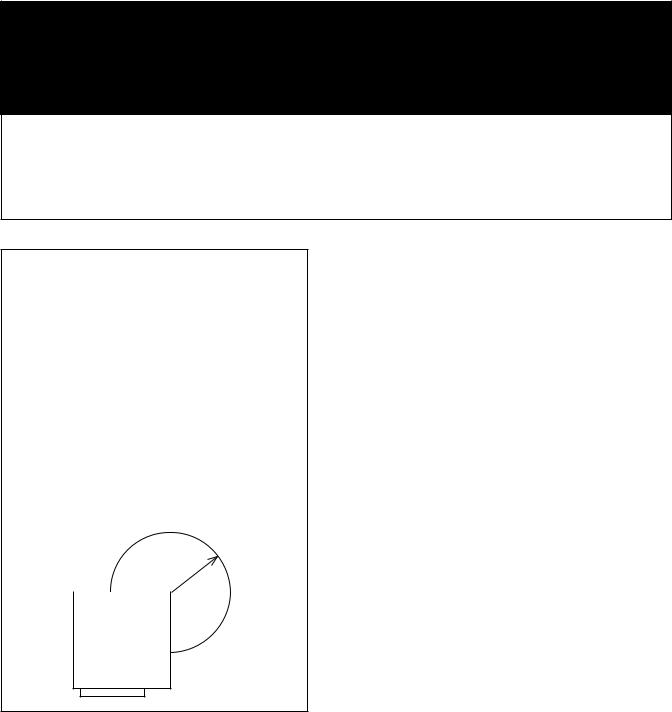
Steam Free Zone: The SmartSteam Boilerless Steamer can be damaged by steam from external sources. Do not install the steamer over a steam venting drain. Ensure that steam is not present in an area bounded by the footprint of the steamer and a circle 18 inches in radius
about the right rear corner of the steamer (see igure below).
18 -inch |
|
|
radius |
|
|
|
57 |
mm |
|
|
|
|
|
|
SMArTSTEAM
(top view)
tHe area DirectlY arounD tHe appliance must be cleareD of all combustible material. failure to folloW tHese instructions can cause boDilY inJurY anD/or propertY Damage.
The steamer must be disconnected from the gas supply system during any pressure testing of that system which has test pressures in exxcess of 1/ PSI ( . 5 kPa).
2.electrical supply connection
Provide 115 VAC, 60 HZ, 1 PH, 15 AMP service. Bring wire in through hole in the lower left back panel. Each cavity requires a separate cord for connections. Local codes and/or the National Electrical Code should be observed in accordance with ANSI/NFPA 70. an
electrical grounD is reQuireD.
The wiring diagram is located in the service compartment and in this manual. Maximum load is 1/ AMPs. In Canada, provide electrical service in accordance with the Canadian Electrical Code, CSA C . Part 1 and/or local codes.
3.gas supply connection
Connection to the gas supply shall be in accordance with the chart below.
Install and operate the gas appliance in a well ventilated area. Adequate air must be supplied to replenish the air used for combustion. Installation must conform with local codes and/or with the
Naitonal Fuel Gas Code, ANSI Z .1/NFPA-5 (latest edition) or the National Gas and Propane Code CSA B1 9.1 as applicable.
Any item which might obstruct or restrict the low of
air for combustion and ventilation must be removed.
Do not obstruct the lue cover or rear vents after
installation.
5
ssb-steamer |
|
npt pipe size required |
|
||
|
|
|
SSB- G |
|
1/ |
( )SSB- G |
|
1/ |
SSB-5G |
|
1/ |
( )SSB-5G |
|
1/ |
SSB-10G |
|
/ |
( )SSB-10G |
|
/ |

om-ssb-3g/5g/10gf
Ratings for Gas Smart Steam
*Measured on top of gas valve
|
|
|
|
min |
|
|
maX |
|
|
|
|
|
Incoming |
Incoming |
|||
|
|
*operating |
Gas Feed |
Gas Feed |
||||
btu |
pressure |
rate |
|
rate |
||||
G NG |
|
5 ,000 |
. 0” WC |
|
5” WC |
1 ” WC |
||
|
|
|
|
|
|
|
||
G LP |
|
5 ,000 |
10.5” WC |
|
1 ” WC |
1 ” WC |
||
|
|
|
|
|
|
|
||
5G NG |
|
6 ,000 |
. 5” WC |
|
5” WC |
1 ” WC |
||
|
|
|
|
|
|
|
||
5G LP |
|
6 ,000 |
10.5” WC |
|
1 ” WC |
1 ” WC |
||
|
|
|
|
|
|
|
||
10GF NG |
|
106,000 |
. 0” WC |
|
5” WC |
1 ” WC |
||
|
|
|
|
|
|
|
||
10GF LP |
|
106,000 |
10.5” WC |
|
1 ” WC |
1 ” WC |
||
|
|
|
|
|
|
|
|
|
In Canada, the installation must conform to the Canadian Gas Code, CAN 1-B1 9, Installation
Codes for Gas BurningAppliances and Equipment and/or local codes.
After the unit has been connected to the gas supply,
all gas joints must be checked for leaks. Do not use lame checking for leaks. A thick soap solution or
other suitable leak detector should be used.
for a unit on casters:
A.The installation shall be made with a connector that complies witht the standard for connectors for movable gas appliances. ANSI Z 1.69.CSA 6.16, and a quickdisconnect devise that complies with the standard for quick-disconnect devices for use with gas fuel, ANSI Z 1. 1.CSA 6.9.
B.Adequate means must be provided to limit the movement of the appliance without depending on the connector and the quickdisconnect device or its associated piping to limit the appliance movement.
C.The location where the restraining device
may be attached to the appliance shall be in acordance with Groen speciications for the device.
4.Water connection(s)
Install a check valve to prevent back low in the incoming cold water line, as required by local plumbing codes. Water pressure in the line should be between 0 and 60 PSI. If pressure is above 60 PSI, a pressure regulator will be needed. These pressures will provide the 1.5 gallons per minute required for proper steamer function.
A / inch female NH connector (garden hose type) is used to attach the water supply to the inlet valve. minimum inside diameter of the
water feed line is 1/2 inch. Use a washer in the hose connection. Do not allow the connection to leak, no matter how slowly. Do not over-tighten
hose connections.
CoLd WATER PRESSURE 30-60 PSI
This equipment is to be installed to comply withthebasicplumbingcodeoftheBuildingOficials
and Code Administrators International, Inc. (BOCA) and the Food Service Sanitation Manual of the Food and Drug Administration (FDA).
NOTE: Local code may also require check valves in the water supply line.
5.Drain connection
Level the steamer front to back, or pitch it slightly to the rear (maximum 1/ inch) by adjusting the optional legs or the bullet feet on the optional stand.
ssb |
Drain ID Hose Size |
|
|
SSB- G |
1.5 |
|
|
( )SSB- G |
2.5 |
SSB-5G |
1.5 |
( )SSB-5G |
2.5 |
SSB-10G |
2.0 |
( )SSB-10G |
2.0 |
|
|
Warning:
Do not connect tHe Drain DirectlY to a builDing Drain. blocKing tHe Drain is HaZarDous.
There must be a free air gap between the end of the hose and the building drain. The free air gap should be as close as possible tot he unit drain. There must also be no other elbows or restrictions between the unit drain and the free air gap.
caution
Do not use plastic pipe. Drain must be rateD for boiiling Water.
Install the drain line with a constant downward pitch.
important: do not allow water traps in the line. A trap can cause pressure buildi\up in the cavity, which may cause the door gasket to leak.
proper Drain line connection –– Drain line must have a constant downward pitch of at least 1/4” per foot. observe local code regarding air gap spacing and drain connections.5.
6
 Loading...