


Gorenje KAS35ININVDC, KAS21INTT, KAS26ININVDC, KAS35INTT, KAS26INTT User Manual
...USERS AND INSTALLATION MANUAL
UPUTE ZA UPORABU I POSTAVLJANJE
UPUTE ZA UPORABU I POSTAVLJANJE
UPUTE ZA UPORABU I POSTAVLJANJE
ІНСТРУКЦІЇ З ВИКОРИСТАННЯ ТА МОНТАЖУ
НАСТЕННАЯ СПЛИТ СИСТЕМА КОНДИЦИОНИРОВАНИЯ ВОЗДУХА ИНСТРУКЦИЯ
FRANÇAIS NEDERLANDS
Thank you very much for purchasing this Air Conditioner. Please read this use and installation instructions carefully before installing and using this appliance and keep this manual for future reference.

USERS AND INSTALLATION MANUAL
Thank you very much for purchasing this Air Conditioner. Please read these use and installation instructions carefully before installing and using this appliance and keep this manual for future reference.
DEUTSCHFRANÇAIS ЯЗЫК РУССКИЙNEDERLANDS PORTUGUÊS ESPAÑOL ITALIANO

EN
Safety introduction |
1 |
|||||||||||||||||||||||||||||||||||||||||||||||||||||||||||||||||||||||||||||||||||||||||||||||||||||||||||||||||||||||||||||||||||||||||||||||||||||||||||||||||||||||||||||||||||||||||||||||||||||||||||||||||||||||||||||||||||||||||||||||||||||||||||||||||||||||||||||||||||||||||||||||
Preparation before use |
3 |
|||||||||||||||||||||||||||||||||||||||||||||||||||||||||||||||||||||||||||||||||||||||||||||||||||||||||||||||||||||||||||||||||||||||||||||||||||||||||||||||||||||||||||||||||||||||||||||||||||||||||||||||||||||||||||||||||||||||||||||||||||||||||||||||||||||||||||||||||||||||||||||||
Safety precautions |
4 |
|||||||||||||||||||||||||||||||||||||||||||||||||||||||||||||||||||||||||||||||||||||||||||||||||||||||||||||||||||||||||||||||||||||||||||||||||||||||||||||||||||||||||||||||||||||||||||||||||||||||||||||||||||||||||||||||||||||||||||||||||||||||||||||||||||||||||||||||||||||||||||||||
Installation instructions |
|
|
|
|
|
|
|
|
|
|
|
|
|
|
|
|
|
|
|
|
|
|
|
|
|
|
|
|
|
|
|
|
|
|
|
|
|
|
|
|
|
|
|
|
|
|
|
|
|
|
|
|
|
|
|
|
|
|
|
|
|
|
|
|
|
|
|
|
|
|
|
|
|
|
|
|
|
|
|
|
|
|
|
|
|
|
|
|
|
|
|
|
|
|
|
|
|
|
|
|
|
|
|
|
|
|
|
|
|
|
|
|
|
|
|
|
|
|
|
|
|
|
|
|
|
|
|
|
|
|
|
|
|
|
|
|
|
|
|
|
|
|
|
|
|
|
|
|
|
|
|
|
|
|
|
|
|
|
|
|
|
|
|
|
|
|
|
|
|
|
|
|
|
|
|
|
|
|
|
|
|
|
|
|
|
|
|
|
|
|
|
|
|
|
|
|
||||||||||||||||||||||||||||||||||||||||||||||||||||||||||||||||||||||||||||||||||||||||||||
Installation diagram |
|
|
|
|
|
|
|
|
|
|
|
|
|
|
|
|
|
|
|
|
|
|
|
|
|
|
|
|
|
|
|
|
|
|
|
|
|
|
|
|
|
|
|
|
|
|
|
|
|
|
|
|
|
|
|
|
|
|
|
|
|
|
|
|
|
|
|
|
|
|
|
|
|
|
|
|
|
|
|
|
|
|
|
|
|
|
|
|
|
|
|
|
|
|
|
|
|
|
5 |
|||||||||||||||||||||||||||||||||||||||||||||||||||||||||||||||||||||||||||||||||||||||||||||||||||||||||||||||||||||||||||||||||||||||||||||||||||||||||||||||||||||||||||||||||||||||||||||
Select the installation locations |
|
|
|
|
|
|
|
|
|
|
|
|
|
|
|
|
|
|
|
|
|
|
|
|
|
|
|
|
|
|
|
|
|
|
|
|
|
|
|
|
|
|
|
|
|
|
|
|
|
|
|
|
|
|
|
|
|
|
|
|
|
|
|
|
|
|
|
|
|
|
|
|
|
|
|
|
|
|
|
|
|
|
|
|
|
|
|
|
|
|
|
|
|
|
|
|
|
|
|
|
|
|
|
|
|
|
|
|
|
|
|
|
|
|
|
|
|
|
|
|
|
|
|
|
|
|
|
|
|
|
|
|
|
|
|
|
|
|
|
|
|
|
|
|
|
|
|
|
|
|
|
|
|
|
|
|
|
|
|
|
|
|
|
|
|
|
|
|
|
|
|
|
|
|
|
|
|
|
|
|
|
|
|
|
|
|
|
|
|
|
|
|
|
|
6 |
|||||||||||||||||||||||||||||||||||||||||||||||||||||||||||||||||||||||||||||||||||||||||||||
Indoor unit installation |
|
|
|
|
|
|
|
|
|
|
|
|
|
|
|
|
|
|
|
|
|
|
|
|
|
|
|
|
|
|
|
|
|
|
|
|
|
|
|
|
|
|
|
|
|
|
|
|
|
|
|
|
|
|
|
|
|
|
|
|
|
|
|
|
|
|
|
|
|
|
|
|
|
|
|
|
|
|
|
|
|
|
|
|
|
|
|
|
|
|
|
|
|
|
7 |
|||||||||||||||||||||||||||||||||||||||||||||||||||||||||||||||||||||||||||||||||||||||||||||||||||||||||||||||||||||||||||||||||||||||||||||||||||||||||||||||||||||||||||||||||||||||||||||||||
Outdoor unit installation |
|
|
|
|
|
|
|
|
|
|
|
|
|
|
|
|
|
|
|
|
|
|
|
|
|
|
|
|
|
|
|
|
|
|
|
|
|
|
|
|
|
|
|
|
|
|
|
|
|
|
|
|
|
|
|
|
|
|
|
|
|
|
|
|
|
|
|
|
|
|
|
|
|
|
|
|
|
|
|
|
|
|
|
|
|
|
13 |
|||||||||||||||||||||||||||||||||||||||||||||||||||||||||||||||||||||||||||||||||||||||||||||||||||||||||||||||||||||||||||||||||||||||||||||||||||||||||||||||||||||||||||||||||||||||||||||||||||||||||
Air purging |
|
|
|
|
|
|
|
|
|
|
|
|
|
|
|
|
|
|
|
|
12 |
|||||||||||||||||||||||||||||||||||||||||||||||||||||||||||||||||||||||||||||||||||||||||||||||||||||||||||||||||||||||||||||||||||||||||||||||||||||||||||||||||||||||||||||||||||||||||||||||||||||||||||||||||||||||||||||||||||||||||||||||||||||||||||||||||||||||||||
Maintenance |
15 |
|||||||||||||||||||||||||||||||||||||||||||||||||||||||||||||||||||||||||||||||||||||||||||||||||||||||||||||||||||||||||||||||||||||||||||||||||||||||||||||||||||||||||||||||||||||||||||||||||||||||||||||||||||||||||||||||||||||||||||||||||||||||||||||||||||||||||||||||||||||||||||||||
Protection |
|
|
|
|
|
|
|
|
|
|
|
|
|
|
|
|
|
|
|
|
|
|
|
|
|
|
|
|
|
|
|
|
|
|
|
|
|
|
|
|
|
|
|
|
|
|
|
|
|
|
|
|
|
|
|
|
|
|
|
|
|
|
|
|
|
|
|
|
|
|
|
|
|
|
|
|
|
|
|
|
|
|
|
|
|
|
|
|
|
|
|
|
|
|
|
|
|
|
|
|
|
|
|
|
|
|
|
|
|
|
|
|
|
|
|
|
|
|
|
|
|
|
|
|
|
|
|
|
|
|
|
|
|
|
|
|
|
|
|
|
|
|
|
|
|
|
|
|
|
|
|
|
|
|
|
|
|
|
|
|
|
|
|
|
|
|
|
|
|
|
|
|
|
|
|
|
|
|
|
|
|
|
|
|
|
|
|
|
|
|
|
|
|
|
|
|
|
|
|
|
|
|
|
|
|
|
|
|
|
|
|
|
|
|
|
|
|
|
|
|
|
|
|
|
|
|
|
|
|
|
16 |
|||||||||||||||||||||||||||||||||||||||||||||||||||||||||
Troubleshooting |
17 |
|||||||||||||||||||||||||||||||||||||||||||||||||||||||||||||||||||||||||||||||||||||||||||||||||||||||||||||||||||||||||||||||||||||||||||||||||||||||||||||||||||||||||||||||||||||||||||||||||||||||||||||||||||||||||||||||||||||||||||||||||||||||||||||||||||||||||||||||||||||||||||||||
Identification of parts |
18 |
|||||||||||||||||||||||||||||||||||||||||||||||||||||||||||||||||||||||||||||||||||||||||||||||||||||||||||||||||||||||||||||||||||||||||||||||||||||||||||||||||||||||||||||||||||||||||||||||||||||||||||||||||||||||||||||||||||||||||||||||||||||||||||||||||||||||||||||||||||||||||||||||
Indoor unit |
|
|
|
|
|
|
|
|
|
|
|
|
|
|
|
|
|
|
|
|
|
|
|
|
|
|
|
|
|
|
|
|
|
|
|
|
|
|
|
|
|
|
|
|
|
|
|
|
|
|
|
|
|
|
|
|
|
|
|
|
|
|
|
|
|
|
|
|
|
|
|
|
|
|
|
|
|
|
|
|
|
|
|
|
|
|
|
|
|
|
|
|
|
|
|
|
|
|
|
|
|
|
|
|
|
|
|
|
|
|
|
|
|
|
|
|
18 |
|||||||||||||||||||||||||||||||||||||||||||||||||||||||||||||||||||||||||||||||||||||||||||||||||||||||||||||||||||||||||||||||||||||||||||||||||||||||||||||||||||||||||||
Outdoor unit |
|
|
|
|
|
|
|
|
|
|
|
|
|
|
|
|
|
|
|
|
|
|
|
|
|
|
|
|
|
|
|
|
|
|
|
|
|
|
|
|
|
|
|
|
|
|
|
|
|
|
|
|
|
|
|
|
|
|
|
|
|
|
|
|
|
|
|
|
|
|
|
|
|
|
|
|
|
|
|
|
|
|
|
|
|
|
|
|
|
|
|
|
|
|
|
|
|
|
|
|
|
|
|
|
|
|
|
|
|
|
|
|
|
18 |
||||||||||||||||||||||||||||||||||||||||||||||||||||||||||||||||||||||||||||||||||||||||||||||||||||||||||||||||||||||||||||||||||||||||||||||||||||||||||||||||||||||||||||||
Display introduction |
|
|
19 |
|||||||||||||||||||||||||||||||||||||||||||||||||||||||||||||||||||||||||||||||||||||||||||||||||||||||||||||||||||||||||||||||||||||||||||||||||||||||||||||||||||||||||||||||||||||||||||||||||||||||||||||||||||||||||||||||||||||||||||||||||||||||||||||||||||||||||||||||||||||||||||||
Remote controller operating instructions. See" remote controller instructions".

EN
1.To guarantee the unit work normally, please read the manual carefully before installation, and try to install strictly according to this manual.
2.Do not let air enter the refrigeration system or discharge refrigerant when moving
the air conditioner.
3.Properly ground the air conditioner into the earth.
4.Check the connecting cables and pipes carefully, make sure they are correct and firm before connecting the power of the air conditioner.
5.There must be an air-break switch.
6.After installing, the consumer must operate the air conditioner correctly
according to this manual, keep a suitable storage for maintenance and moving of the air conditioner in the future.
7.Fuse of indoor unit: T3.15A 250VAC or T5A250VAC. Please refer to the screen printing on the circuit board for the actual parameters, which must be consistent with the parameters on the screen printing.
8.The installation instructions for appliances that are intended to be permanently connected to fixed wiring and have a leakage current that may exceed 10 mA, must state that the installation of a residual current device (RCD) having a rated residual operating current not exceeding 30 mA is advisable.
9.Warning: Risk of electric shock can cause injury or death: Disconnect all remote electric power supplies before servicing.
10.The maximum length of the connecting pipe between the indoor unit and outdoor unit should be less than 5 meters. It will affect the efficiency of the air conditioner if the distance longer than that length.
11.This appliance is not intended for use by persons (including children) with reduced physical, sensory or mental capabilities, or lack of experience and knowledge, unless they have been given supervision or instruction concerning use of the appliance by a person responsible for their safety. Children should be supervised to ensure that they do not play with the appliance.
12.This appliance can be used by children aged from 8 years and above and persons with reduced physical, sensory or mental capabilities or lack of experience and knowledge if they have been given supervision or instruction concerning use of the appliance in a safe way and understand the hazards involved. Children must not play with the appliance. Cleaning and user maintenance must not be made by children without supervision.
13.The batteries in remote controller must be recycled or disposed of properly. Disposal of Scrap Batteries --- Please discard the batteries as sorted municipal waste at the accessible collection point.
14.If the appliance is fixed wiring, the appliance must be fitted with means for disconnection from the supply mains having a contact separation in all poles that provide full disconnection under over voltage category III conditions, and these means must be incorporated in the fixed wiring in accordance with the wiring rules. If the supply cord is damaged, it must be replaced by the manufacturer, its service agent or similarly qualified persons in order to avoid a hazard.
-1-

EN
15.If the supply cord is damaged, it must be replaced by the manufacturer, its service agent or similarly qualified persons in order to avoid a hazard.
16.The appliance must be installed in accordance with national wiring regulations.
17.The air conditioner must be installed by professional or qualified persons.
18.The appliance must not be installed in the laundry.
19.Regarding to installation, please refer to section “Installation instructions”.
20.Regarding to maintenance, please refer to section “Maintenance”.
-2-
EN
Note
When charging refrigerant into the system, make sure to charge in liquid state, if the refrigerant of the appliance is R410A. Otherwise, chemical composition of refrigerant R410A inside the system may change and thus affect performance of the air conditioner.
 According to the character of refrigerant (R410A, the value of GWP is 2088), the pressure of the tube is very high, so be sure to be careful when you install and repair the appliance.
 If the supply cord is damaged, it must be replaced by the manufacturer, its service agent or similarly qualified persons in order to avoid a hazard.
 The air conditioner must be installed by a professional engineer.
 The temperature of refrigerant circuit will be high, please keep the interconnection cable away from the copper tube.
Preset
Before using the air conditioner, be sure to check and preset as the following.
Remote Controller presetting
Each time after the remote control is replaced with new batteries or is energized, remote control auto presetting heat pump. If the air conditioner you purchased is a Cooling Only one, heat pump remote controller can also be used.
Back-light function (optional)
Hold down any button of the remote controller for about 2 seconds, the back-light will be turned on. It will be turned off automatically after about 10 seconds.
Auto Restart Presetting
The air conditioner has Auto-Restart function.
You can set or cancel this function when the air conditioner is running.
 Hold down the emergency button (ON/OFF) for a few seconds, this function will be set if you hear beep twice. If you just hear beep once, this function will be canceled.
This appliance is made of recyclable or re-usable material. Scrapping must be carried out in compliance with local waste disposal regulations. Before scrapping it, make sure to cut off the mains cord so that the appliance cannot be re-used.
For more detailed information on handling and recycling this product, contact your local authorities who deal with the separate collection of rubbish or the shop where you bought the appliance.
SCRAPPING OF APPLIANCE
This appliance is marked according to the European Directive 2012/19/EC, Waste Electrical and Electronic Equipment (WEEE).
This marking indicates that this product should not be disposed
with other household wastes throughout the EU. To prevent possible harm to the environment or human health from uncontrolled waste disposal, recycle it responsibly to promote the sustainable reuse of material resources. To return your used device, please use the return and collection systems or contact the retailer where the product was purchased. They can take this product for environmentally safe recycling.
-3-
EN
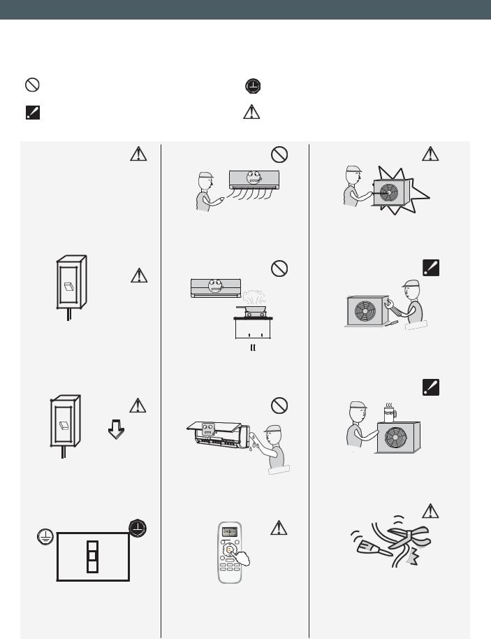
Symbols in this Use and Care Manual are interpreted as shown below.
Be sure not to do. |
Grounding is essential. |
|
Pay attention to such a situation. |
Warning: Incorrect handling could |
|
cause a serious hazard, such as death, |
||
|
||
|
serious injury, etc. |
Use correct power supply in accordance with the rating plate requirement. Otherwise, serious faults or hazard may occur, or a fire may break out.
ON
OFF
It is harmful to your health if the cool air reaches you for a long time. It is advisable to let the airflow be directed to the entire room.
Never insert a stick or similar obstacle to the unit. Since the fan rotates at high speed, this may cause an injury.
Keep the power supply circuit breaker or plug from dirt. Connect the power supply cord to it firmly and correctly, lest an electric shock or a fire break out due to insufficient contact.
Prevent the air flow from reaching the gas burners and stove.
Do not repair the appliance by yourself. If this is done incorrectly, it may cause an electric shock, etc.
ON
OFF
Do not use the power supply circuit breaker or pull off the plug to turn it off during operation. This may cause a fire due to spark, etc.
It is the user's responsibility to make the appliance be grounded according to local codes or ordinances by a licensed technician.
Do not touch the operation buttons when your hands are wet.
Turn off the appliance by remote control first before cutting off power supply if malfunction occurs.
-4-
Do not put any objects on the outdoor unit.
Do not knit, pull or press the power supply cord, lest the power supply cord be broken. An electric shock or fire is probably caused by a broken power supply cord.
EN
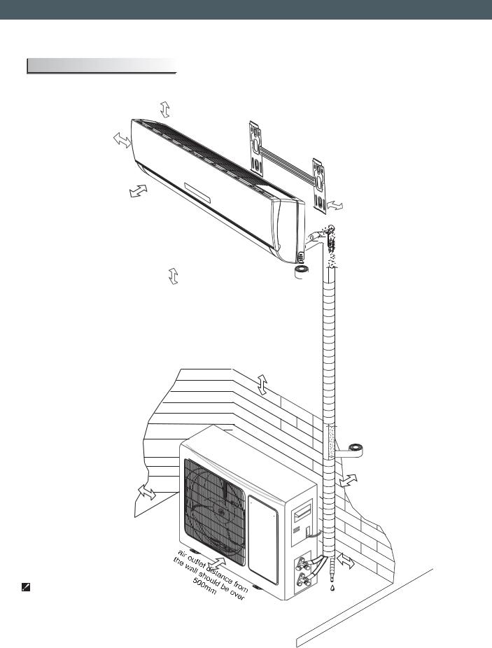
Installation diagram
|
Distance from ceiling |
Distance from wall |
should be over 200 mm |
|
|
should be over 50mm |
|
Distance from the obstacle |
Distance from the wall |
|
should be over 3000mm. |
||
should be over 50mm |
||
|
Distance from floor should be over 2500mm.
Distance from the obstacle should be over 500mm.
Air intake distance from the wall should be over 250mm
 Above figure is only a simple presentation of the unit, it may not match the external appearance of the unit you purchased.
 Installation must be performed in accordance with
the national wiring standards by authorized personnel only.
-5-
Air intake distance from the wall should be over 250mm
over 250mm
EN
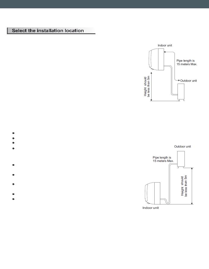
Location for Installing Indoor Unit
 Where there is no obstacle near the air outlet and air can be easily blown to every corner.
 Where piping and wall hole can be easily arranged.
 Keep the required space from the unit to the ceiling and wall according to the installation diagram on the previous page.
 Where the air filter can be easily removed.
 Keep the unit and remote controller 1m or more away from television, radio etc.
 Keep as far as possible from fluorescent lamps.
 Do not put anything near the air inlet to obstruct it from air absorption.
 Install on a wall that is strong enough to bear the weight of the unit.
 Install in a place that will not increase operation noise and vibration.
  Keep away from direct sunlight and heating sources. Do not place flammable materials or combustion apparatuses on top of the unit.
Location for Installing Outdoor Unit
Where it is convenient to install and well ventilated. Avoid installing it where flammable gas could leak. Keep the required distance from the wall.
The pipe length between indoor and outdoor unit should be not more than 5 meters in factory default status, but it can go up to maximum 15 meters with additional refrigerant charge.
Keep the outdoor unit away from greasy dirt, vulcanization gas exit.
Avoid installing it by the roadside where there is a risk of muddy water.
A fixed base where it is not subject to increased operation noise.
Where there is not any blockage of the air outlet.
Avoid installing under direct sunlight, in an aisle or sideway, or near heat sources and ventilation fans. Keep away from flammable materials, thick oil fog, and wet or uneven places.
Model |
Max. allowed pipe length |
Limit of pipe |
Limit of Elevation |
Required amount of |
|
without additional |
length (m) |
Difference H (m) |
additional refrigerant (g/m) |
||
|
|||||
|
refrigerant (m) |
|
|
|
|
|
|
|
|
|
|
2kW~5,3kW |
5 |
15 |
5 |
20 |
|
|
|
|
|
|
|
6kW~7,3kW |
5 |
15 |
5 |
30 |
|
|
|
|
|
|
|
8,8kW~10kW |
5 |
15 |
5 |
40 |
|
|
|
|
|
|
If the height or pipe length is out of the scope of the table, please consult the dealer.
-6-
EN
Indoor unit installation
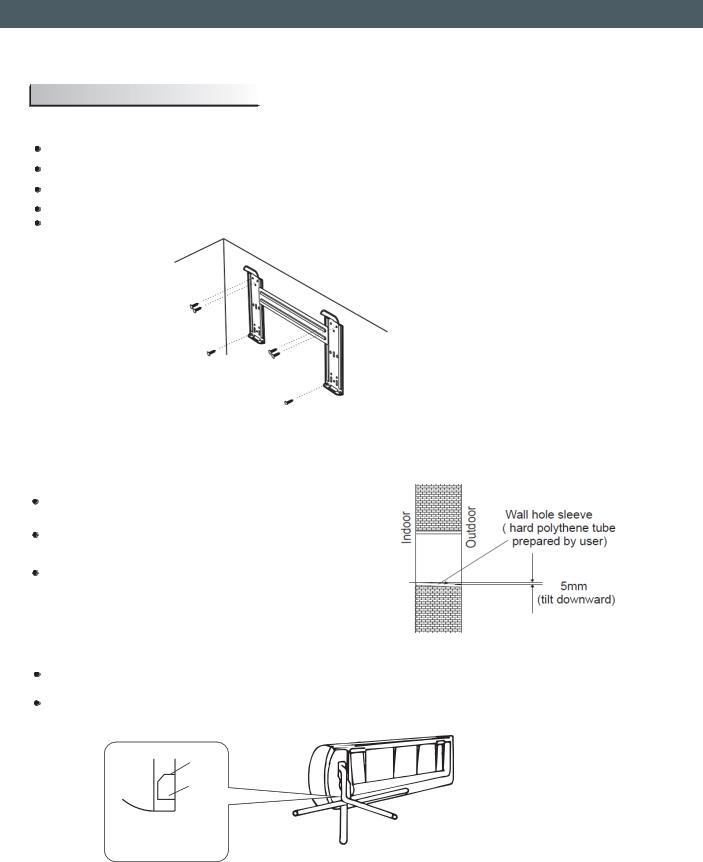
1. Installing the Mounting Plate
Decide an installing location for the mounting plate according to the indoor unit location and piping direction.
Keep the mounting plate horizontally with a horizontal ruler or dropping line.
Drill holes of 32mm in depth on the wall for fixing the plate.
Insert the plastic plugs to the hole, fix the mounting plate with tapping screws. Inspect if the mounting plate is well fixed. Then drill a hole for piping.
Tapping screw
Mounting plate
Note: The shape of your mounting plate may be different from the one above, but the installation method is similar.
Note: As the above figure shows, the six holes matched with tapping screw on the mounting plate must be used to fix the mounting plate, the others are prepared.
2. Drill a Hole for Piping
Decide the position of hole for piping according to the location of mounting plate.
Drill a hole on the wall. The hole should tilt a little downward toward outside.
Install a sleeve through the wall hole to keep the wall tidy and clean.
3. Indoor Unit Piping Installation
Put the piping (liquid and gas pipe) and cables through the wall hole from outside or put them through from inside after indoor piping and cables connection complete so as to connect to outdoor unit.
Decide whether to saw the unloading piece off in accordance with the piping direction (as shown below).
Piping direction
trough |
|
|
Unloading |
|
|
piece |
|
|
1 |
|
4 |
|
|
|
Saw the unloading piece |
3 |
Note: When installing the pipe at the directions |
|
||
|
1,2 or 4, saw the corresponding unloading piece |
|
off along the trough |
|
|
2 |
|
off the indoor unit base. |
After connecting piping as required, install the drain hose. Then connect the power cords. After connecting, wrap the piping, cords and drain hose together with thermal insulation materials.
-7-

EN
Piping Joints Thermal Insulation:
Wrap the piping joints with thermal insulation materials and then wrap with vinyl tape.
Piping Thermal Insulation:
a.Place the drain hose under the piping.
b.Insulation material uses polythene foam over 6mm in thickness.
Note: Drain hose is prepared by user.
Drain pipe should point downward for easy drain flow.
Do not arrange the drain pipe twisted, sticking out or wave around, do not immerse the end of it in water.
If an extension drain hose is connected to the drain pipe, make sure to thermal insulated when passing along the indoor unit.
When the piping is directed to the right, piping, power cord, and drain pipe should be thermal insulated and fixed onto the back of the unit with a piping fixer.
|
|
|
large |
|
|
large |
|
|
|
pipe |
|
|
pipe |
|
|
drain |
small |
|
drain |
small |
|
|
|
hose |
|||
|
|
hose |
pipe |
|
pipe |
|
|
|
|
|
|
||
Base |
Piping fixer |
Base |
Piping fixer |
Base |
|
Hook here |
|
|
|||||
|
|
|
|
|
|
A. Insert the pipe fixer to the slot.
B. Press to hook the pipe fixer onto the base.
Note: The unit of 5,3kW#,7kW#,10,5kW is bigger than the unit of 5,3kW#,7kW#,10,5kW
-8-
EN
4. Connecting of the Cable
 Indoor Unit
Connect the power connecting cord to the indoor unit by connecting the wires to the terminals on the control board individually in accordance with the outdoor unit connection.
Note: For some models, it is necessary to remove the cabinet to connect to indoor unit terminal.
Outdoor Unit
1). Remove the access door from the unit by loosening the screw. Connect the wires to the terminals on the control board individually as the following.
2). Secure the power connecting cord onto the control board with cable clamp.
3). Reinstall the access door to the original position with the screw.
4) Use a recognized circuit breaker for 7kW model or above between the power source and the unit.
A disconnecting device to adequately disconnected all supply lines must be fitted.
Caution:
Front Terminal
Cabine
Indoor
Chassi
Access door Terminal(ins ide)
Outdoor unit
The figures in this manual are based on the external view of a standard model. Consequently, the shape may differ from that of the air conditioner you have selected.
1. Never fail to have an individual power circuit specifically for the air conditioner. As for the method of wiring, refer to the circuit diagram posted on the inside of the access door.
2.Confirm that the cable thickness is as specified in the power source specification. 3.Check the wires and make sure that they are all tightly fastened after cable connection. 4. Be sure to install an earth leakage circuit breaker in wet or moist area.
Cable Specifications
Capacity |
Power cord |
|
|
Power connecting cord |
Power connecting cord1 |
Main |
||||
|
|
|
|
|
|
|
|
power |
||
(kW) |
|
|
|
|
|
|
|
|
||
Type |
Normal cross |
Type |
Normal cross |
Type |
Normal cross |
supply |
||||
|
||||||||||
|
-sectional area |
- sectional area |
- sectional area |
|
||||||
|
|
|
|
|
||||||
|
|
|
|
|
|
|
|
|
|
|
1,5 ~ 3,8 |
H05VV-F |
0.75~1.5mm |
2 |
X3 |
H07RN-F |
1.5mm2X3 |
H05RN-F |
0.75mm2X2 |
To indoor |
|
|
H05RN-F |
0.75~1.0mm2X3 |
(Heat-pump) |
|||||||
|
|
|
|
|
|
|
|
|||
4,1 ~ 7 |
H05VV-F |
1.5~2.5mm2X3 |
H07RN-F |
1.5~2.5mm2X3 |
H05RN-F |
0.75mm2X2 |
To indoor |
|||
|
|
|
|
|
|
|
|
(Heat-pump) |
|
|
|
|
|
|
|
|
|
|
|||
5,3 ~ 8,8 |
H05VV-F |
1.5~2.5mm2X3 |
H07RN-F |
1.5~2.5mm2X4 |
H05RN-F |
0.75mm2X2 |
To indoor |
|||
|
|
|
|
|
|
|
|
(Heat-pump&Optional) |
|
|
|
|
|
|
|
|
|
|
|
|
|
5,3 ~ 8,8 |
H07RN-F |
2 |
|
|
H05RN-F |
1.0mm2X3 |
H05RN-F |
0.75mm2X3 |
To outdoor |
|
2.5mm X3 |
H07RN-F |
1.0mm2X4Cooling only |
(Heat-pump) |
|||||||
|
|
|
|
|
|
|
|
|
||
7 ~ 10,6 |
H07RN-F |
2 |
|
H05RN-F |
0.75mm2X4 |
H05RN-F |
0.75mm2X2 |
To outdoor |
||
|
2.5~4.0mm X3 |
H07RN-F |
1.0mm2X4 |
|
(Heat-pump&Optional) |
|||||
|
|
|
|
|
|
|
|
|
||
7 ~ 10,6 |
H07RN-F |
1.5mm2X5 |
|
|
H05RN-F |
0.75mm2X4 |
H05RN-F |
0.75mm2X2 |
To outdoor |
|
|
|
|
|
|
|
|
|
(Heat-pump) |
|
|
The cord may be different from the list above. It may be used as the next list. And it can be larger. 0-6A, use 0.75mm2 or 18AWG. 0-10A, use 1mm2 or 16AWG. 0-16A, use 1.5mm2 or 14AWG. 0-20A, use 2.5mm2 or 14AWG. 0-25A, use 2.5mm2 or 12AWG. 0-32A, use 4mm2.
-9-
EN
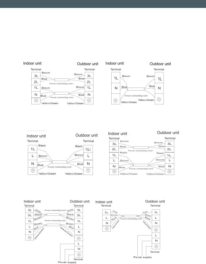
Wiring Diagram
Warning: Before obtaining access to terminals, all supply circuits must be disconnected.
Note: All the wires may be of different colors. The indicators ‘1L 2L 3L’ may be ‘4 5 6’ or others.
And the terminal may be different from the material object.
 1,5kW~7kW Model
For above models, the power supply is connected from indoor unit.
For these models, the ground wire may be connected to the electric box directly.
 5,3kW~8,8kW Model
For above models, the power supply is connected from indoor unit.
For these models, the ground wire may be connected to the electric box directly.
 5,3kW~8,8kW Model
For these models, the power supply is connected from outdoor unit, with a circuit breaker.
-10-
EN
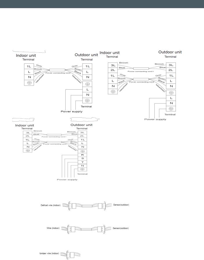
Warning: Before obtaining access to terminals, all supply circuits must be disconnected.
Note: All the wires may be of different colors. The indicators ‘1L 2L 3L’ may be ‘4 5 6’ or others.
And the terminal may be different from the material object.
 7kW~10,6kW Model
For these models, the power supply is connected from outdoor unit, with a circuit breaker. All the wires may be different colors.
 Defrost cable (for heat-pump air conditioner only, and it`s an optional part)
After connection, the defrost wire should be well wrapped with a wrapping tape and the connector should be put inside the unit.
 Overheat protection or high-pressure protection cable (it`s an optional part)
After connection, the wire should be well wrapped with a wrapping tape and the connector should be put inside the unit.
 Ionizer (The ionizer is an optional part)
After connection, the ionizer will work automatically.
-11-
EN
Outdoor unit installation
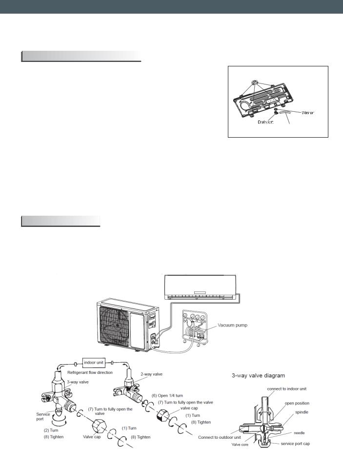
1.Install Drain Port and Drain Hose (for heat-pump model only)
The condensate drains from the outdoor unit when the unit operates in heating mode. In order not to disturb your neighbor and protect the environment, install a drain port and a drain hose to direct the condensate water. Just install the drain port and rubber washer to the chassis of the outdoor unit, then connect a drain hose to the port as the right figure shown.
2. Install and Fix Outdoor Unit
Rubber pad (optional)
Place under the leg pedestal
Drain hose (prepared by user)
Fix with bolts and nuts tightly on a flat and strong floor.
If installed on the wall or roof, make sure to fix the supporter well to prevent it from shaking due to serious vibration or strong wind.
3. Outdoor Unit Piping Connection
 Remove the valve caps from the 2-way and 3-way valve.
 Connect the pipes to the 2-way and 3-way valves separately according to the required torque. 4. Outdoor Unit Cable Connection (see previous page)
Air purging
The air which contains moisture remaining in the refrigeration cycle may cause a malfunction on the compressor. After connecting the indoor and outdoor units, release air and moisture from the refrigerant cycle using a vacuum pump, as shown below.
Note: To protect the environment, be sure not to discharge the refrigerant to the air directly.
-12-

EN
How to Purge Air Tubes:
(1). Unscrew and remove caps from 2 and 3-way valves.
(2). Unscrew and remove cap from service valve.
(3). Connect vacuum pump flexible hose to the service valve.
(4). Start vacuum pump for 10-15 minutes until reaching a vacuum of 10 mm Hg absolutes.
(5). With vacuum pump still running, close the low-pressure knob on vacuum pump manifold. Then stop vacuum pump.
(6). Open 2-way valve 1/4 turn, then close it after 10 seconds. Check tightness of all joints using liquid soap or an electronic leak detector.
(7). Turn 2 and 3-way valves stem to fully the valves. Disconnect vacuum pump flexible hose.
(8). Replace and tighten all valve caps.
-13-

EN
 Front panel maintenance
Cut off the power supply |
|
a |
|
|
|
Grasp position "a" and |
|
Turn off the appliance |
|
pull outward to remove the |
|
first before disconnecting |
|
front panel. |
|
from power supply. |
|
|
|
|
|
|
a |
|
|
|
|
Wipe with a soft |
|
Never use volatile substance |
|
|
such as gasoline or polishing |
||
and dry cloth. |
|
||
|
powder to clean the appliance. |
||
|
|
||
Use soft moisture cloth |
Use a dry and |
|
|
soft cloth to |
|
|
|
to clean if the front panel |
|
|
|
clean it. |
|
|
|
is very dirty; |
|
|
|
|
|
|
|
|
|
||
Never sprinkle water onto the |
Reinstall and shut the front panel. |
||
indoor |
|
Reinstall and shut the front panel by |
|
unit |
|
||
|
pressing position "b" downward. |
||
|
|
b |
b |
|
|
|
|
|
Dangerous! |
|
|
|
Electric |
|
|
|
shock! |
|
|
|
|
|
|
 Air filter maintenance
Stop the appliance, cut off the
power supply and remove the air Clean and reinstall the air filter. filter.
|
If the dirt is conspicuous, |
|
|
wash it with a solution of |
|
1 |
detergent in lukewarm water. |
|
After cleaning, dry well in |
||
|
||
2 |
shade. |
|
|
3 |
1.Open the front panel.
2.Press the handle of the filter gently from the front.
3.Grasp the handle and slide out the filter.
Close the front panel again.
 Clean the air filter every two weeks if the air conditioner operates in an extremely dusty environment.
It is necessary to clean the air filter after using it for about 100 hours.
-14-
EN
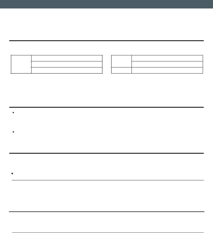
 Operating condition
The protective device maybe trip and stop the appliance in the cases listed below.
Outdoor air temperature is over 24oC HEATING Outdoor air temperature is below -7oC
Room temperature is over 27oC
COOLING
Outdoor air temperature is over *43oC
Room temperature is below 21oC
DRY |
Room temperature is below 18oC |
*For Tropical (T3) Climate condition models, the temperature point is 55 instead of 43 .
The temperature of some products is allowed beyond the range. In specific situation, please consult the dealer. If the air conditioner runs in COOLING or DRY mode with door or window opened for a long time when
relative humidity is above 80%, dew may drip down from the outlet.
 Noise pollution
Install the air conditioner at a place that can bear its weight in order to operate more quietly.
 Install the outdoor unit at a place where the air discharge and the operation noise would not annoy your neighbors.
Do not place any obstacles in front of the air outlet of the outdoor unit lest it increases the noise level.
 Features of protector
1. The protective device will work at following cases.
 Restarting the unit at once after operation stops or changing mode during operation, you need to wait for 3 minutes.
Connect to power supply and turn on the unit at once, it may start 20 seconds later.
2.If all operation has stopped, press ON/OFF button again to restart. Timer should be set again if it has been canceled.
 Features of HEATING mode
Preheat
At the beginning of the HEATING operation, the airflow from the indoor unit is discharged 2-5 minutes later.
Defrost
In HEATING operation, the appliance will defrost (de-ice) automatically to raise efficiency. This procedure usually lasts 2-10 minutes. During defrosting, fans stop operation.
After defrosting completes, it returns to HEATING mode automatically.
Note: Heating is NOT available for cooling only air conditioner models.
-15-
EN
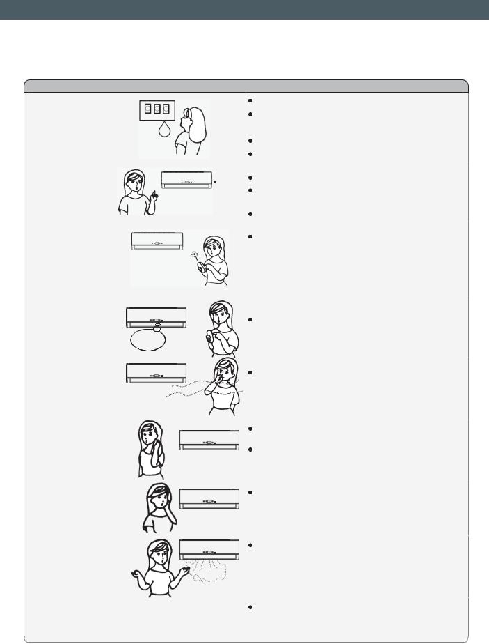
The following cases may not always be a malfunction, please check it before asking for service.
Trouble |
|
Analysis |
|
|
If the protector trip or fuse is blown. |
Does not run |
|
Please wait for 3 minutes and start again, |
|
protector device may be preventing unit to work. |
|
|
|
. |
|
|
If batteries in the remote controller exhausted. |
|
|
If the plug is not properly plugged. |
|
|
|
No cooling or |
|
Is the air filter dirty? |
|
|
|
heating air |
|
Are the intakes and outlets of the air |
|
|
conditioner blocked |
|
|
Is the temperature set properly |
|
|
|
|
|
If strong interference (from excessive static |
|
|
electricity discharge, power supply voltage |
Ineffective control |
|
abnormality) presents, operation will be |
|
|
abnormal. In such case, disconnect from |
|
|
the power supply and connect back 2-3 |
|
|
seconds later. |
|
|
|
Does not operate |
|
Changing mode during operation, 3 minutes |
immediately |
|
will delay. |
don't run |
|
|
|
|
|
|
|
This odor may come from another source |
Peculiar odor |
|
such as furniture, cigarette etc., which is |
|
|
sucked in the unit and blows out with the air. |
|
|
|
A sound of |
|
Caused by the flow of refrigerant in the |
flowing water |
|
air conditioner, not a trouble. |
|
|
Defrosting sound in heating mode. |
|
|
|
Cracking sound is |
|
The sound may be generated by the expansion |
|
or contraction of the front panel due to change |
|
heard |
|
|
|
of temperature. |
|
|
|
|
|
|
|
Spray mist from |
|
Mist appears when the room air becomes |
|
very cold because of cool air discharged |
|
the outlet |
|
|
|
from indoor unit during COOLING or DRY |
|
|
|
|
|
|
operation mode. |
|
|
|
The compressor indicator (red) lights on |
|
The unit is shifting from heating mode to defrost. |
constantly, and indoor fan stops. |
|
The indicator will turn off within ten minutes and |
|
|
return to heating mode. |
|
|
|
|
-16- |
|
EN
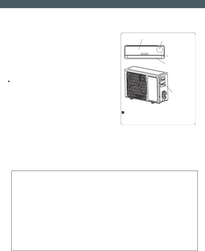
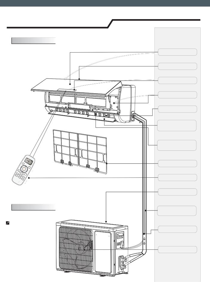
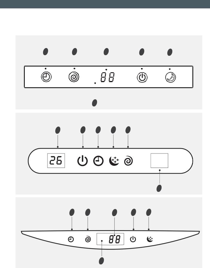
Identification of parts
Indoor unit
Outdoor unit
The figures in this manual are based on the external view of a standard model. Consequently, the shape may differ from that of the air conditioner you have selected.
-17-
Front Panel
Air Intake
Display Panel
Emergency Panel
Air Outlet
Vertical Adjustment
Louver
Horizontal Adjustment
Louver
Air Filter
Remote Controller
Air Intake
Pipes and Power
Connection Cord
Drain Hose
Note: Condensate water drains at COOLING or DRY operation.
Air Outlet
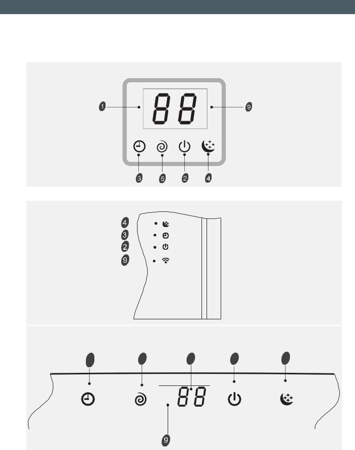
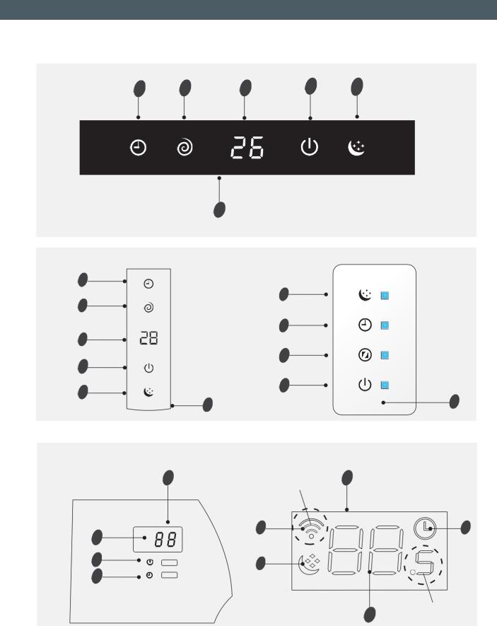
Temperature indicator |
1 |
Display set temperature.
It shows FC after 200 hours of usage as reminder to clean the filter.
After filter cleaning press the filter reset button located on the indoor unit behind the front panel in order to reset the display (optional).
|
Running indicator |
2 |
|
|
|
Run |
It lights up when the AC is running. |
|
|
It flashes during defrosting. |
|
Timer |
Timer indicator |
3 |
It lights up during set time. |
|
|
|
|
|
Sleep |
Sleep indicator |
4 |
|
||
It lights up in sleep mode. |
|
|
|
|
|
|
Compressor indicator |
5 |
Comp. |
|
|
It lights up when the compressor is on. |
|
|
|
Super indicator |
6 |
|
|
|
|
It lights up in super mode. |
|
|
Mode indicator |
7 |
|
Heating displays orange, others display white |
|
|
Fan speed indicator |
8 |
|
Signal Receptor |
9 |
|
Smart WIFI indicator |
10 |
|
It lights up during WIFI is on. |
|
VG/VL series
1 |
2 |
3 |
4 |
5 |
9 |
-18-
EN
VT series
3 |
5 |
1 |
2 |
4 |
|
|
|
|
|
|
|
|
|
|
|
|
|
|
|
|
|
|
|
|
|
|
|
|
|
9
SF/DG(Right side) series
1 |
2 |
3 |
4 |
5 |
9
SE series
3 |
5 |
1 |
2 |
4 |
9
-19-
EN
NS/DE series
NT series
VQ/TE/TF/DA/DG(Middle)/DH/DL(Right side) series |
|
|
||
3 |
5 |
1 |
2 |
4 |
-20-
EN
VM series |
|
|
2 |
|
3 |
5 |
1 |
4 |
9
NM/DF series |
NK series |
3
4
5
3
1
6
2
2
4
9 |
9 |
|
TA/TC series |
TQ/TR series |
|
1 |
optional |
9 |
|
|
10 |
3 |
9
2 |
4 |
|
3
optional
1
-21-
EN
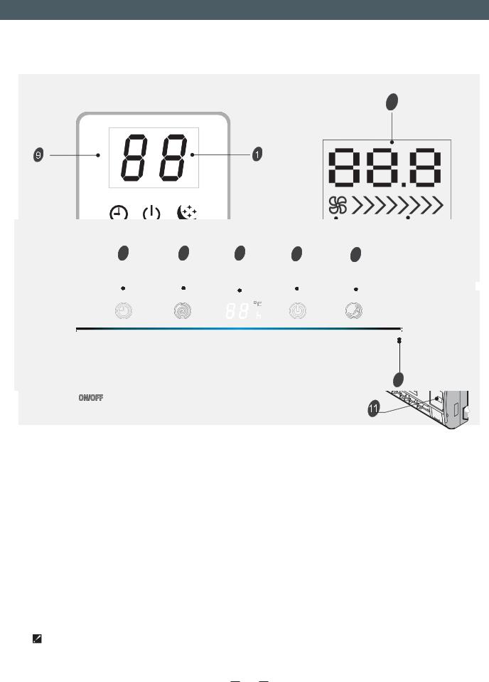
SA/TD/TG/TS/DB/DC/DJ/DK/DL(Middle) series |
SC series |
1
Timer |
Comp. |
Run |
Sleep |
VC series
3 |
5 |
1 |
2 |
7 |
4 |
82 |
|
|
|
|
|
Timer |
Comp. |
Run |
Sleep |
|
|
|
|
|
|
|
|
|
|
|
|
Emergency button 11
9
To let the AC run or stop by pressing the button.
The symbols may be different from these models, but the functions are similar.
23

UPUTSTVO ZA UPOTREBU I POSTAVLJANJE
Zahvaljujemo na kupovini ovog klima uređaja. Molimo da pre postavljanja i upotrebe uređaja pažljivo pročitate ovo uputstvo za postavljanje i upotrebu, kao i da ga sačuvate za buduću upotrebu.
DEUTSCHFRANÇAISЯЗЫК РУССКИЙNEDERLANDS PORTUGUÊS ESPAÑOL ITALIANO
HR
Sadržaj
Bezbednosni saveti |
1 |
||||||||||||||||||
Pre upotrebe |
3 |
||||||||||||||||||
Mere opreza |
4 |
||||||||||||||||||
Upustvo za postavljanje |
|
|
|
||||||||||||||||
Prikaz postavljanja |
|
5 |
|||||||||||||||||
|
|
|
|
|
|
|
|
|
|
|
|
|
|
|
|
|
|
|
|
Izaberite mesta postavljanja |
|
6 |
|||||||||||||||||
Postavljanje unutrašnje jedinice |
|
7 |
|||||||||||||||||
Postavljanje spoljašnje jedinice |
13 |
||||||||||||||||||
|
|
|
|
|
|
|
|
|
|
|
|
|
|
|
|
|
|
|
|
Čišćenje vazduhom |
12 |
||||||||||||||||||
|
|
|
|
|
|
|
|
|
|
|
|
|
|
|
|
|
|
|
|
Održavanje |
15 |
||||||||||||||||||
|
|
|
|
|
|
|
|
|
|
|
|
|
|
|
|
|
|
16 |
|
Uklanjanje teškoća |
17 |
||||||||||||||||||
Opis delova |
18 |
||||||||||||||||||
Unutrašnja jedinica |
|
18 |
|||||||||||||||||
Spoljašnja jedinica |
|
18 |
|||||||||||||||||
Prikaz displeja |
|
|
|
|
|
|
|
|
|
19 |
|||||||||
Za rukovanje daljinskim upravljačem pogledajte "uputstva za upotrebu daljinskog upravljača".
HR
Sadržaj
1. Da biste obezbedili nesmetano funksionisanje uređaja, najpre pažljivo pročitate uputstvo i striktno ga se pridržavate prilikom postavljanja uređaja.
2. Nemojte dozvoliti da vazduh prodre u rashladni sistem ili ispustite rashladno
sredstvo dok pomerate klima uređaj. 3. Pravilno uzemljite klima uređaj.
4. Pažljivo proverite priključne kablove i creva i uverite su da su ispravni i pričvršćeni pre nego što priključite klima uređaj na napon.
5. Mora postojati prekidač za isključenje vazduha.
Nakon postavljanja uređaja potrošač mora pravilno rukovati klima uređajem, u skladu sa ovim uputstvom, koje takođe mora odgovarjauće čuvati za buduće održavanje i premeštanje klima uređaja.
6. Osigurač unutrašnje jedinice: T3.15 A 250 VAC ili T5 A 250 VAC. Za stvarne parametre pratite prikaz na natpisnoj pločici, koji moraju da budu u skladu sa parametrima na displeju.
7. U uputstvu za postavljanje uređaja namenjenih stalnom priključenju na fiksno ožičenje sa strujom odvoda koja može da premaši 10 mA mora biti navedeno da se preporučuje postavljanje uređaja za diferencijalnu zaštitu (RCD) sa naznačenom preostalom radnom strujom koja ne prekoračuje 30 mA.
8. Upozorenje: opasnost od strujnog udara može da uzrokuje povrede ili smrt. Pre servisiranja isključite sve jedinice udaljenog napajanja električnom energijom.
9. Priključno crevo između unutrašnje i spoljašnje jedinice ne sme da bude duže od 5 metara. Veća dužina creva će da utiče efikasnost klima uređaja.
10. Ovaj uređaj ne smeju sa koriste osobe (uključujući i decu) sa smanjenim fizičkim, senzornim ili duševnim sposobnostima, kao ni osobe sa nedovoljnim iskustvom i znanjem, osim ako nisu dobili nadzor ili uputstvo za upotrebu uređaja od lica koje je odgovorno za njihovu bezbednost . Decu morate nadgledati da biste sprečili da se igraju uređajem .
11. Ovaj uređaj mogu da koriste deca starija od 8 godina i osobe sa smanjenim fizičkim, senzornim ili duševnim sposobnostima, kao i osobe sa nedovoljnim iskustvom i znanjem samo ako su na bezbedan način dobili nadzor ili uputstvo za upotrebu uređaja te razumeju uključene opasnosti. Deca ne smeju da se igraju sa uređajem. Deca bez nadzora ne smeju da obavljaju čišćenje ni korisničko održavanje .
12. Baterije iz daljinskog upravljača moraju pravilno da se odlažu i recikliraju. Odlaganje otpadnih baterija --- Molimo da baterije odlažete odvojeno od komunalnog otpada na odgovarajućem mestu za sakupljanje.
13. Ako je uređaj namenjen stalnom priključenju na fiksno ožičenje, mora da bude opremljen zaštitom za isključenje iz naponske mreže sa odvojenim kontaktima na svim polovima, koja obezbeđuje potpuno isključenje pod uslovima prenaponske kategorije III i koja mora da bude ugrađena u fiksno ožičenje u skladu sa pravilima ožičenja.
-1-

HR
Sadržaj
14. Ako je priključni kabl oštećen, mora ga zameniti proizvođač, ovlašćeni serviser, odnosno drugo kvlaifikovano lice, da bi se sprečila opasnost.
15. Uređaj mora da bude postavljen u skladu sa nacionalnim propisima od ožičenju.
16. Postavljanje klima uređaja mora da izvrši stručno, odnosno kvalif ikovano osoblje.
17. Uređaj ne sme da bude postavljen u perionici veša.
18. Za postavljanje uređaja pratite poglavlje “Uputstvo za postavljanje”. 19. Za održavanje uređaja pratite poglavlje “Održavanje”.
-2-

HR
Sadržaj
Napomena
Ako je za punjenje sistema rashladnim sredstvom predviđeno sredstvo R410A, napunite uređaj rashladnim sredstvom u tečnom stanju. U suprotnom bi mogao da se promeni hemijski sastav rashladnog sredstva R410A u unutrašnjosti sistema, što bi uticalo na rad klima uređaja.
 S obzirom na simbol rashladnog sredstva (R410A – vrednost GWP je 2088), pritisak cevi je veoma visok, zato budite pažljivi prilikom postavljanja i popravke uređaja.
 Ako je priključni kabl oštećen, mora ga zameniti proizvođač, ovlašćeni serviser ili drugo kvalifikovano lice, da bi se sprečila opasnost.
 Klima uređaj mora da izvrši stručno, odnosno kvalifikovano osoblje.
 Neka kabl za međusobno spajanje bude udaljen od bakarne cevi, jer će temperatura kruga rashladnog srestva biti visoka.
Podešavanje postavki unapred
Pre upotrebe klima uređaja proverite i podesite postavke unapred:
Svaki put kad stavite ili zamenite baterije u daljinskom upravljaču, automatski je podešeno daljinsko upravljanje toplotne pumpe. Ako je klima uređaj koji ste kupili namenjen samo hlađenju, takođe možete da koristite daljinski upravljač toplotne pumpe.
Funkcija osvetljenja pozadine (opciono)
Pritisnite bilo koji taster daljinskog upravljača u trajanju od oko 2 sekunde i uključiće se osvetljenje pozadine. Automatski će se isključiti nakon 10 sekundi.
Automatsko ponovno pokretanje postavki podešenih unapred
Klima uređaj ima funkciju automatskog ponovnog pokretanja. Tu funkciju možete da podesite ili poništite dok klima uređaj radi.
 Pritisnite taster za zaustavljanje (ON/OFF) u trajanju od nekoliko sekundi i funkcija je podešena ako čujete dvostruki zvučni signal. Ako čujete jednostruki zvučni signal, funkcija je poništena.
Ovaj uređaj je proizveden od materijala koji može da se reciklira, odnosno ponovo upotrebi. Odlaganje mora da bude izvršeno u skladu sa lokalnim propisima o zbrinjavanju otpada. Pre odlaganje proverite da li je mrežni kabl odrezan da biste sprečili ponovnu upotrebu uređaja.
Za više informacija o postupanju i recikliranju ovog proizvoda obratite se lokalnim telima koja su nadležna za odvojeno sakupljanje otpada ili prodajnom mestu na kom ste kupili uređaj.
ODLAGANJE UREĐAJA
Ovaj uređaj je označen u skladu sa evropskom direktivom 2012/19/EC o otpadnoj električnoj i elektronskoj opremi (WEEE).
Ovaj simbol znači da se proizvod ne sme odlagati sa drugim kućnim otpadom i važi širom EU. Da biste sprečili štetu za životnu sredinu ili ljudsko zdravlje zbog nekontrolisanog odlaganja otpada, reciklirajte ovaj proizvod i dajte svoj doprinos održivoj ponovnoj upotrebi materijalnih izvora. Za vrećanje starih proizvoda koristite sisteme sakupljanja i odlaganja ili se obratite prodajnom mestu na kom ste ih kupili. Oni mogu preuzeti ovaj proizvod u svrhu ekološki besprekornog recikliranja.
-3-
 Loading...