

Page 1

EXIT MANUAL
ALLEN BRADLEY
7/16/97
Click here to
Click here to
EXIT Manual
EXIT Manual
OPERATOR MANUAL
Page 2
Attention symbols
Some of the warnings, instructions and advice in this manual are so
important that we used the following special symbols to draw attention
to them:
Warnings
This symbol indicates a warning. Injury or even death may
result if you do not heed it.
This symbol is also used to mark out safety components
etc. See section ”Safety devices, a survey” in chapter
”Introduction” in the OPERATOR MANUAL or chapter
”Maintenance” in the SERVICE MANUAL.
Instructions
EXIT MANUAL
Advice
This symbol indicates instructions which are important, for
example to prevent damage to the s terilizer and/or the load.
This symbol indicates important advice and hints that
make it easier to work with the sterilizer.
Page 3

OPERATOR MANUAL
TABLE OF CONTENTS
Attention symbols
1. INTRODUCTION
Introduction GE . . . . . . . . . . . . . . . . . . . . . . . . . . . . . . . . . 1
Safety devices, a survey . . . . . . . . . . . . . . . . . . . . . . . . . . . . 2
2. THE PROCESS
Steam/vacuum-process . . . . . . . . . . . . . . . . . . . . . . . . . . . . 1
Chamber leak test . . . . . . . . . . . . . . . . . . . . . . . . . . . . . . . 2
EXIT MANUAL
3. INSTRUMENTS AND CONTROLS
4. OPERATION
Start-up . . . . . . . . . . . . . . . . . . . . . . . . . . . . . . . . . . . . . 1
General advice when using the sterilizer . . . . . . . . . . . . . . . . . . . . 2
Monitoring the load temperature when sterilizing liquids . . . . . . . . . . . . 2
5. INSTALLATION
Unpacking . . . . . . . . . . . . . . . . . . . . . . . . . . . . . . . . . . . 1
Storage . . . . . . . . . . . . . . . . . . . . . . . . . . . . . . . . . . . . . 1
Installation . . . . . . . . . . . . . . . . . . . . . . . . . . . . . . . . . . . 1
Connection . . . . . . . . . . . . . . . . . . . . . . . . . . . . . . . . . . . 2
Electricity . . . . . . . . . . . . . . . . . . . . . . . . . . . . . . . . . . . . 3
Water . . . . . . . . . . . . . . . . . . . . . . . . . . . . . . . . . . . . . . 4
Steam . . . . . . . . . . . . . . . . . . . . . . . . . . . . . . . . . . . . . 5
Compressed air . . . . . . . . . . . . . . . . . . . . . . . . . . . . . . . . 9
Exhaust from safety valve . . . . . . . . . . . . . . . . . . . . . . . . . . .10
Drain . . . . . . . . . . . . . . . . . . . . . . . . . . . . . . . . . . . . . .11
Ventilation . . . . . . . . . . . . . . . . . . . . . . . . . . . . . . . . . . .11
Functional test prior to use . . . . . . . . . . . . . . . . . . . . . . . . . . .11
6. OPERATING INSTRUCTION
Preoperation checks . . . . . . . . . . . . . . . . . . . . . . . . . . . . . . 2
Sterilizing . . . . . . . . . . . . . . . . . . . . . . . . . . . . . . . . . . . . 2
Page 4

Close down . . . . . . . . . . . . . . . . . . . . . . . . . . . . . . . . . . . 3
Blowing safety valve . . . . . . . . . . . . . . . . . . . . . . . . . . . . . . 3
Program Combinations . . . . . . . . . . . . . . . . . . . . . . . . . . . . . 4
7. CONTROL UNIT ALLEN BRADLEY
Operating panel SLC 504 . . . . . . . . . . . . . . . . . . . . . . . . . . . 2
Push Buttons/ Indicator Lights - Load Side . . . . . . . . . . . . . . . . . . . 4
Push Buttons/Indicator Lights - Unload Side . . . . . . . . . . . . . . . . . . 5
Passwords . . . . . . . . . . . . . . . . . . . . . . . . . . . . . . . . . . . 6
Detailed screen dis p lays . . . . . . . . . . . . . . . . . . . . . . . . . . . . 7
Alarm and System Messages - Troubleshooting . . . . . . . . . . . . . . . .26
System Interlocks - Horizontal Doors . . . . . . . . . . . . . . . . . . . . .36
Technical data . . . . . . . . . . . . . . . . . . . . . . . . . . . . . . . . .37
EXIT MANUAL
Page 5
1. INTRODUCTION
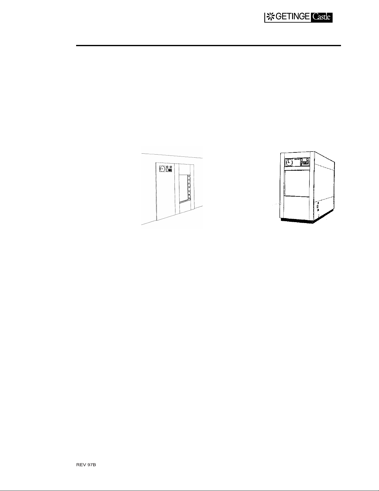
Introduction GE
Sterilizer type GE is the collective designation of a range of GETINGE
high pressure sterilizers using steam and vacuum in the process for sterilization. GE-sterilizers are available with vertically or horizontally
sliding doors. Both single an d double ended types exist.
EXIT MANUAL
The GE-sterilizers are intended for sterilizati on of materials in the
health service as well as in the pharmaceutical industry. The type of
materials include: instruments, utensil s, glass, plastic, leather and textiles. Some sterilizers have special programs for sterilization of hot and
cold liquids. The dominant sterilizing agent is steam at a temperature of
120-135 °C.
Adaptation to r especti ve steril izat ion req uire ment s is made pri mari ly
by selecting the type of software for the control unit. The sterilizer control unit is compu terized and prov ides for a large variety of processe s
with very good accuracy in control of the process parameters. Both real
time and set values for a process may be displayed on request.
The software which controls the processes can be preprogrammed
with cycle parameters to provide spee d and safety in the production
line. When it come s to un ique c ycles, m any pr oc ess pa rame ter s can be
modified from time to time by the operator.
Reprogramming of t he control unit can be made on site.
The automatic doors are provided with safety devices to pro tect the
operator.
The sterilizer chamber, mad e of acid pr oof stainl ess steel, i s covered
externally by seal-welded u-channel. About half of the chamber area is
covered by these u-chann els. The y serve b oth a s stif fe ning b ars for t he
1.1
Page 6
EXIT MANUAL
pressure vessel and a s a stea m ja cket pro vidi ng t emper atur e c ontr olled
steam heating for the chamber walls.
The GE-type sterilizers should be supplied with electricity, cold
water, compressed air and steam. If central steam is not available or
there are reasons not to use it, GE-units can be equipped with an electric
steam generator.
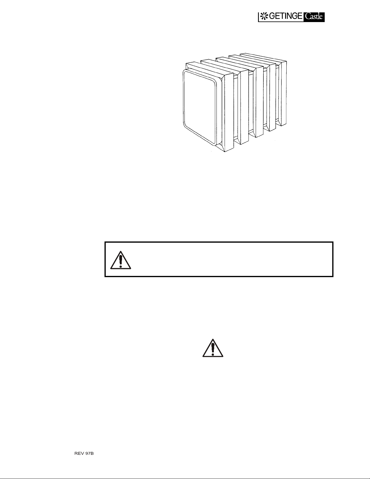
Safety devices, a survey
The panels of the sterilizer shall prevent the operator
access to the inner parts of the sterilizer. Only specially
trained personnel have access to the inner parts.
Safety components
Every sterilizer is equipped with a number of compo nents the purpose
of which is to specifically guarantee human safety. These items are
marked with the sign below:
Electric diagrams
•
Piping diagrams
•
These components have been subject to special tests before being
accepted as safety components and must therefore not be substituted by
any make or execution not approved by Getinge/Castle, Inc.
It is of greatest importance that these components are kept in good
working condition in order to maintain a safe function during the sterilizer life time.
1.2
Page 7

Doors
EXIT MANUAL
The sign is used not only to point out important components, but also
to emphasize such other safety factors re quiring special attention as
measurements, tolerances, material etc.
The doors are kept closed by the automatic control unit while cycles are
in progress and also when supply media fail. The doors do not open until
the condition chamber pressure = atmopheric pressure is fulfilled, not
even in case of an electric failure causing an opening command. The
vertically slid ing door i s actuated b y a compressed ai r cylinde r with a
choked air inlet. A much larger outlet is arranged directly at the cylinder
end. Objects stopping the upward motion of the door will exert pressure
on a plate running the entire length of the top of the door. The plate acts
directly upon the outlet valve which opens thereby interrupting the door
motion. This will prevent operator injuries and material damage. A
brace stops the door from opening in case the pneumatic cylinder should
unintentionally become depressurized. The brace can not be removed in
case the compressed air pressure is to low to keep the door in the upper
position.
Emergency stop
Trim plates
Valves
In the front pa nel, at the side of the do or, the re is a push but ton mounte d
having dual functions:
A While actuating the door:
To stop the door motion immediately.
A push on the button releases an alarm resulting in th e door stopping its motion.
B Whil e the door is closed:
During a cycle, the process is aborted and all valves for media to the
chamber close. This releases an alarm.
Panels may be removed by means of tools or keys. The panels form a
barrier for operators, but not for specially trained technicians. Stainless
steel surfaces within reach of the operating personnel are insulated and
cooled to a safe temperature.
As standard, electric and pneumatically actuated valves are normally
closed (forced closed by means of a spring force when not actuated).
This prevents undesired flow through th e valves in case of power failure. A fail safe function is a chieved.
1.3
Page 8

Pressure vessel
The sterilizer chamber and jacket are pressure vessels, built in accordance with regulations stip ulated by ASME.
The pressure vessels are protected against excess pressure by use of
safety valves.
The pressure vessels and safety valves comply with Section VIII of
ASME pressure vessel code.
Monitoring the pressure behind the door seal
All valves admitting medium to the chamb er are kept closed until the
pressure behind the door seal is high en ough to guar antee th e ti ghtne ss
of the chamber.
Monitoring the load temperature when sterilizing liquids
When running a liquid cycle, the doors are kept closed until the temperature of the liquid has fallen below its boiling point.
EXIT MANUAL
1.4
Page 9
2. THE PROCESS
Steam/vacuum-process
As the sterilizer is equipped with a vacuum pump it can serve as an ordinary steam sterilizer, suitable for sterilization of utensils, containers,
textiles etc.
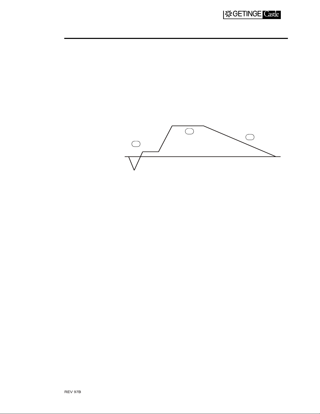
The universal steam/vacuum process can be divided into pretreatment
(A), sterilizing (B) and post-treatment (C).
A
EXIT MANUAL
B
C
Pretreatment
Sterilizing
It has been generally accepted that moisture is an essential element in
achieving sterility with steam. Therefore it is important that th e steam
comes in close contact with the microorganisms to be killed. Any air
present serves as an ins ulation which preve nts the contact and low ers
the temperature.
A pretreatment p hase, consisting of a nu mber of pressure varia tions
following a certai n pattern , effectiv ely remove s air from v arious type s
of goods and produces the moisture required in the subsequent sterilizing phase.
Air removal when autoclaving aqueous solutions in open containers is
made by a single prevacuum or by steam-air displacement. This prevents the liquid from boiling during the decompression periods that
occurs in a pulsating procedure.
The sterilization timer starts fr om the moment when the chambe r temperature transducer signals a temperature equal to or higher than the
chamber temperature set point. Count down of the sterilizing time stops
at temperatures below this sterilizing temperature.
When sterilizing goods, in particular liquids, where the sterilizing
temperature is measured within the goods, load sensors are used. The
2.1
Page 10
Post treatment
EXIT MANUAL
condition for starting the sterilization timer is when the chamber sensor
and all load sensors indicate a tempe rature equal to or above nominal
sterilizing temperature
The post treatment is in tended to normaliz e the t emperatur e and moisture content of the goods. All types of goods, except liquids, are
exposed to a deep vacuum for a certain period of time.
The post treatment of aqueo us solutions sterilized in open or vented
containers consi sts of a period of natural coolin g. The pressure a nd temperature are lowered slowly until the temperature of the liqu id is safely
below its boiling point. This process is speeded up by applying a slight
vacuum to the chamber when its pressure approaches atmospheric.
The sterilizer door will remain sealed by its gasket until atmospheric
pressure prevails in the chamber.
Chamber leak test
The autoclave is equipped with a program for automatic leak test of the
autoclave chamber. A leak test shall be performed with empty chamber.
The leak test process has its own program number (See list of programs).
The vacuum pump evacuates the chamber. The pump stops when a
deep vacuum is reached. For a short period of time after this evacuation
a slight rise of the chamber pressure takes place which is not due to leakage but results from evaporation of condensate and temperature pressure changes of the recently evacuated residual steam.
A chamber pressure rise caused by air leakage can not be detected
until the conditions in the chamber are stable. Not earlier than 5 minutes
after the vacuum pump has sto pped should the pressure and time be
measured.
A satisfactory leak test allows for a maximum permissible pressure
raise of 0.5 psig in 1 hour. A failed leak test will result in an alarm.
Test period
2.2
Page 11

Air filter sterilization and test
The sterilizer is eq uipped with a pro gr a m for automatic air-fi lter sterilization.
The filter sterilization ha s its own program number (See list of programs).
The filter is sterilized by passi ng steam throug h the filter and the filt er
housing. A temperature sen so r in the piping controls the temperature.
After sterilization the system is cooled by a restricted ai rflow through
the filter.
EXIT MANUAL
2.3
Page 12

3. INSTRUMENTS AND CONTROLS
Load Side
EXIT MANUAL
1. Jacket pressure gauge 5 Emergency stop
2 Chamber pressure gauge 6 Alarm Acknowledge
3 Operator Panel 7 Open Door
4 Control voltage switch 8 Close Door
Operator panel
Get acquainted with the function of the buttons and signal lights on the
operator panel by studyi ng the in Chapter 7 in the Operator Manual.
Emergency stop
See Safety devices, a survey, Chapter 1 in the
Operator Manuanl.
3.1
Page 13

4. OPERATION
Start-up
Before start-up the operator selects a suitable program. Where appropriate the operator specifies process parameters and other information
requested by the control system.
The process is then started by pressing the start button.
Process start-up is prevented if:
there is an unacknowledged alarm.
•
the door is not closed and interlocked in accordance with the cond i-
•
tions imposed.
the self-checking of the cont rol system has detected a fault at the
•
door limit switch.
EXIT MANUAL
the keyswitch for manual stepping is activated.
•
media supply (i.e. steam or water) is not available (only if the steril-
•
izer is equipped with pressure switches for this).
the jacket temperature has not been reached (only if the process
•
includes jacket heating).
Idling sterilizer
An alarm situation for an idling sterilizer stops it from being started.
Call for a technician.
•
Repeated alarms
In case repeated alarms make it impossible to end the cycle, let an
authorized technicia n end the cycle manually.
When several faults occur, onl y the last will be displayed.
Blowing safety valve
In case the safety valve on the chamber or jac ket blo ws:
Press the EMERGENCY STOP button.
•
If ineffective, cut the power with the wall-mounted disconnect.
•
Call for a technician.
•
4.1
Page 14
General advice when using the sterilizer
Keep the sterilizer door closed when not sterilizing.
•
Be alert to everything that app ears unusual such as leaks, humming
•
solenoid valves, jamming mechan ical devices etc. Remedy the situation before it becomes a malfunction
When loading:
Place all load sensors in the load. Be careful not to cut or run over the
•
sensor cables when loading and unloading, as well as when closi ng
the doors.
When running Steam/vacuum process:
Arrange bowl shaped articles with the hollow part down wards.
•
EXIT MANUAL
Empty containers (bottles, flasks, test glasses etc.) should be placed
•
with their openings fac in g do wn wards.
Heavy goods should be placed near bottom of the chamber.
•
Monitoring the load temperature when sterilizing
liquids
If the door on a sterilizer, containing a load of liquids, is
opened before the liquid temperature has fallen below a
certain temperature, closed bottles may explode while
open containers may boil over.
The course may develop violently with great danger to
human life and technical equipment.
Safety arrangements
One or several temperature sensors in the load are sensing the temperature in the liquid. Th ese sensors keep the sterili zer doors closed until
the temperature is safely below the boiling point. An alarm will be emitted in case of a break or short circuit in the sensor.
4.2
Page 15

Weekly cleaning (to be made by the daily operator)
The sterilizer should have cooled down before cleaning.
To reduce the risks for injuries, shut the power of.
1. Clean the chamber drain strainer.
2. a) Remove shelf guides and loose plates.
b) Clean the chamber internally.
c) A non chloric cleaner should be used. If particularly stubborn,
scouring powder or chrome cleaner could be used occasional ly.
Steel wool must never be used!
Sterilizers frequentl y used for sterilization of chloric solutions
demand thorough cleaning as residuals may cause serious corrosion
even in stainless materials. An acetified cleaner is best suited for
this purpose. Thorough rinsing is essential.
3. Clean the sterilizer external stainless steel surfaces w ith a normal
household cleaner that does not contain abrasive. Take care when
cleaning lacquered sur faces, texts and plastic articles.
EXIT MANUAL
4.3
Page 16
5. INSTALLATION
Find out the central point of gravity when lifting and transporting a packed or not packed sterilizer thereby avoiding
serious accidents.
Unpacking
• Check when unpacking the apparatus that the NB No. of its data plate
conforms with the N B No. of the documents.
EXIT MANUAL
Storage
• Check that the sterilizer is undamaged. Any transportation damage
should be reporte d within seven days to the transport company that
was responsible for delivery.
• Do not remove the protective plastic film from stainless steel panels
until the installation is comp leted.
• There is certain equipment, such as expendable items; control unit;
etc. packed inside the sterilizer chamber.
Please note that these articles are specific for each sterilizer. When unpacking more than one sterilizer the articles
are not to be interchanged.
The sterilizer should be st ored in a tempera ture betw een 36oF and 104
°F and at a maximum relative humidity 95% (not condensating).
Installation
• Place the sterilizer close to but never over a drain. Leave a well sized
clearance space on both sides for good operation and easy and saf e
maintenance of the equipment. The back of the sterilizer may if necessary come up close to a wall. See also appropriat e diagrams and
drawings.
5.1
Page 17
Connection
EXIT MANUAL
• Arrange for escape distances, as directed from labor safety point of
view, to be contained.
• Place stainless steel floor pads under each levelling leg to protect the
floor. Adjust the legs to make the loading height fall within specified
dimension, while checking by means of a spirit level that t he sterilizer chamber bottom is horizontal.
Certain installation operations should be carried out by
authorized technicians. This is especially the case when it
comes to electricity, steam water and air.
Faulty accomplished installation may jeopardize the safety
to person and property and invalidates manufacturer's
warranty on the equipment.
Piping and electrical wiring sho uld be made in a neat manner to make
the service compartment look workman like.
• Find out the connection po ints and connection data of the sterilizer
by studying the installation drawings.
• Pay attention to local, state an d national regulations.
• Remove impuriti es by blowing through all pipe s to be connected to
the sterilizer.
• Insulate hot pipes, where necessary, to avoid injury.
• Mark pipes and electrical leads.
Install shut-off valves in the supply lines in an easily accessible location near the equipment so as to avoid risk areas
when using these. Due to the risk of injury an un-accessible area of the service com partment is not a suitable place.
5.2
Page 18
Electricity
EXIT MANUAL
Before welding on or near-by the sterilizer, the boards of
the control system have to be isolated!
Disconnect all plug-in connectors from all PCB’s!
The electric components o f the control unit will tole rate supply line
voltage variations of ±10%. Greater fluctuations demand that a voltage
stabilizer be introduced between the sterilizer automatic fuse and the
control equipment. The latter will cause an inductive load on the stabilizer this should be well over sized (minimum.5 kW). The frequency
deviation may amount to ±1%.
• Check that all electric wire connection screws are tig htened.
Connect the sterilizer to an electric 60 Hz; 3 Ph/ 208 - 480
volts (depending upon pump size) + ground, through a
closely situated disconnect.
The stated voltage is for various versions of the sterilizer.
Check on the equipment arrangement drawing and the utility data sheet for the required electrical connections.
Those documents also give information about power and
fuse ratings that may be important for choos ing the correct
size of cables.
Units equipped with vacuum pumps
Check by manual operation of the direct o n line starter of th e vacuum
pump, that the direction of rotation conforms with the arrow on the
pump housing.
Running the shaft seal dry will destroy it in a few seconds.
Change any two of th e main supp ly wires on their co nnecti on te rmin al
to reverse the direction of rotation.
5.3
Page 19

Water
Cooling water for heat exchanger
The sterilizer has a pressure gauge connected to the coolin g wat er supply pipe. It is no rmally situated in the service area. The cooling water
must not be corrosive, nor must it contain abrasives or scaling particles.
The water salt conten t should not ca use scaling as a resu lt of the temperature. If the cooling water is to be recirculated, the pressure in the
return pipe should be at least 250 kPa (36 psig) lower than in the supply
pipe.
Connect the sterilizer via a shut off valve to a cooling water supply
•
line where the pressure should be a minimum of 350 kPa (50 psig)
and a maximum of 600 kPa (87 psig). A non return valve if necessary
should be supplied by the customer if not otherwise stated in the contract.
EXIT MANUAL
Pump service liquid
TEMPERATURE
Optimal pump operation, for capacity and vacuum depth, is achieved by
a water temperature of 60
of capacity and vacuum dep th is acceptable.
PRESSURE
Connect the sterilizer to a supp ly lin e wi th a mini mum pr essure o f 250
kPa (36 psig) and maximum pressure of 600 kPa (87 psig).
HARDNESS
In order to minimize the sterilizer maintenance and service expenses the
water hardness should not exceed 4 dH. A water softener is recommended where the water is harder than this.
o
F. This temperature can be exceeded, if loss
5.4
Page 20
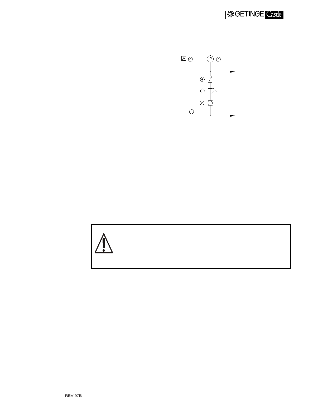
Connection
EXIT MANUAL
A gauge is not required but contributes to easier supervision of the
installation.
1 Main line 2 Shut-off valve
3 Strainer 4 Non-return valve
Steam
5 Pressure gauge 6 Anti-siphon device
Sterilizers not equipped with a built in steam generator must be connected to a central steam supply.
The user is obligated to arrange for safety valves in the
steam supply line as directed.
The effectiveness of a steam st eriliz ation is ver y much de pendent on
the characteristics of the steam used. Therefore some basic demands
should be raised on the quality of steam supplying the sterilizers.
Steam generators based upon evaporation from high pressure hot
water should not be used since the steam produced is of inferior quality
for sterilization purp oses.
Steam Quality
1. Solid particles such as welding pellets, graphite, rust flakes, sand
etc. must not be present since the steam comes in physical contact
with the goods to be sterilized.
2. Liquids, except from steam condensate, must not be present.
5.5
Page 21

3. Gases will prevent a close contact between the steam and the micro-
organisms and should be minimize d as foll ow s:
· Hydrazine (N2H4), NMT 0.11 mg/kg steam.
· Ammonia (NH3), NMT 5 mg/kg steam.
· Air and/or no n-condensa ble gases, NM T 7 ml per 200 ml cond ensate, formed by the steam-air/gas mixture.
4. Other chemicals such as softening residuals and similar particulates
must not be present in sterilizing steam.
· Salt content of NMT 1 mg/kg steam.
Analysis of condensate
An analysis of the condensate from the steam should provide a gauge of
purity. The following should not occur in concentrations exceeding the
values given in ppm condensate:.
EXIT MANUAL
Pressure
Evaporation residuals 1.0ppm of which:
Silicone as SiO2 0.01 ppm
Iron 0.1 ppm
Cadmium 0.005 ppm
Lead 0.05 ppm
Other heavy metals 0.1 ppm
Chloride 0.1 ppm
Phosphate 0 ppm
Recommended pH val ue = 5 - 7
Suitable conductivity < 3 µS/cm (at 68°F)
Suitable hardness ≤ 0.1 dH
Getinge sterilizers should be supplied with steam, pressure in the range
of 36 to 43.5 psig as indicate d by the steril izer pressure gaug e marked
“Steam supply”.
Consult the installa tion drawing for appropriate information.
5.6
Page 22

Moisture content
EXIT MANUAL
Permissible pressure fluctuations of NMT ± 1.45 psig.
If the steam supply line pressure exceeds the sterilizer
working pressure, the user must install a pressure regulating unit and safety valve with relief pressure and sufficient
blow off capacity.
Sterilizers should be supplied with dry saturated steam. The physical
state “dry saturated”, is dif ficult to maintain in a pract ical application ,
and measurement followed by control of the moisture content is an awkward procedure.
The following inform ation is b ased upon practical experien ce and wi ll
generally result in steam with a satisfactory moisture content. This practice will also prevent superheating, a state of steam which is hazardous
in connection with sterilization because i t does not contribute to the
humidification necessary f or inactivation of microorganis ms.
Practical arrangements
1. Conn e c t the sterilize r to a liv e st ea m li ne , not to an inadequa te l y
drained or inadequately vented “dead leg”. Long branch connections to sterilizers should be avoided.
2. Dimension the piping for a steam velocity of 125ft/sec at a pressure
of 36 psig. If several sterilizers are connected to the same pipe, calculate with a simultaneity factor of 0.8.
3. The steam supply pipes should slope to a minimum ratio slope of 1/
8” per foot in the flow direction.
4. Reducing valve(s), should be utili zed in the supply line if the pressure is higher than specified in the installation drawing. The steam
pressure upstream of the reducing valve should not fluctuate more
than 10%. Do not reduce the pressure with a factor smaller than 0.5
in each stage. Use a second reducing valve for greater reduction
ratio. Each reducing valve must be followed by a safety valve.
If the steam in the supply pipe is wet, include a water
serarator as shown in Figure “A”, just before the reducing
valve.
The safety valve exhaus t pi pe sho uld hav e at leas t th e same di mension as the valve exhaust connection and must not contain orifices,
5.7
Page 23

EXIT MANUAL
restrictions or shut off devices. Water pockets formed in the piping,
must be drained.
5. There must be no orifices or restrictions placed in horizontal pipes.
6. Fit the last reducing valve, a distance, not more than 20ft. piping
away from the sterilizer, but not closer than 13ft. if the maximum
reducing ratio of 2:1 is utilized.
If the reducing valve is positioned more than twenty feet
from the sterilizer include a water separator, as shown in
Figure “A”, just before the sterilizer.
7. The last separator device (see figure below) should not be placed
further than 3 feet away from the steri lizer steam intake.
8. No steam consumers other than sterilizers should be connected
down-stream of the last reducing valve.
9. Branch pipes should be connected on top of the horizontal main
pipe.
10. A connection should be provided between the reducing valve and
sterilizer on the steam supply line to ena ble sampling steam for
quality check.
11. Because of potential daily use, the shut off valve should be convenient to the operator.
12. Insulate steam pipes up to the sterilizer steam intake.
An arrangem ent a ccordin g to the follow ing fig ure no rmally sa tisfie s the
demand for dewatering, filtration and supervision facilities when supplying a sterilizer with steam from a main steam supply line.
5.8
Page 24

EXIT MANUAL
1 High-pressure line 8 Vent
2 Labyrinth di ver ter / wa te r
3 Shut-off valve 10 Steam trap
4 Filter 11 Remote-controlled valve
5 Reducing valv e 12 Check valve
6 Safety valve 13 Sterilizer
7 Pressure gauge
Compressed air
The air oil content should be less than 0.02 ppm and maximum permissible water content corresponding to the dew point at 50
Less oil content may be required to satisfy quality demands on the final
product.
Less water content may be required if compressed air pipes or air equi pment is located in non-heated rooms.
separator
9Ball valve
o
F.
Instrument air
The sterilizer is equipped with a pre ssure gauge for instrument air connected to the sterilizer.
5.9
Page 25

EXIT MANUAL
• Connect the sterilizer instrument air supply fitting with a compressed
air source capable of supplying air with a minimum pressure of 80.0
psig and a maximum pressure of 100.0 psig free of oil, water and
solid particles as stipulated abov e.
1 Main supply 2 Shut off valve
3 Strainer 4 Pressure gauge
Chamber and door seal air
If the instrument air line is sufficient for the peak air consumption without causing a pressure drop below 80.0 psig the chamber air may be
connected to the same air supply. A non retur n valve and sterile air filter, if required, should be supplied by the customer unless otherwise
stated in the contract.
• Connect the sterilizer chamber air supply fitting, via a shut off valve,
to a compressed air source capable of supplying air with a minimum
pressure of 43.5 psig and a maximum pressure of 100.0 psig. The air
should be sterile, filtered and free from oil and water as stipulated
above.
Exhaust from safety valve
Safety valves with a small relief opening are provided with exhaust
pipes leading the blown off steam or air to a safe position in the service
area, as defined in ASME Section 8, Div 1. UG - 135.
Safety valves with larger relief open ings are not provided with exhaust
pipes at delivery.
The reason for this is, that when there is the possibility of a large volume
of steam / ai r bei ng ex hauste d, it is advisabl e to have t his pi ped t o a saf e
area where no personnal injury cou ld take place. Refer to OSHA or
State laws concerning this.
An exhaust pipe system connected to the safety valve:
• must be at least the same size as the safety valve
5.10
Page 26

Drain
EXIT MANUAL
• must NOT contain shut -off valves or other throttling devices
• must be designed to avoid the forming of water pockets or, if this is
not possible, provided with drain lines.
WARNING! The outlet from the safety valve must be connected to a pipe leading the exhaust to a safe position.
Sterilizers equipped with more than one waste water connection should
have all piped separat e ly to the floor drain.
Check local regulation s regarding the drain arrangements, ( gas r esid-
uals in the water, tempera ture limits, etc.).
Because most industrial ste rilizers release their pr essure through the
autoclave drain, an air/water separator should be installed to prevent
water splashing in the service area.
• Run a sloping pipe from the outlet with unreduced bore to the drain
where it should terminate not closer than two pipe diameters (air gap)
above the surface leve l of the floor by the wate r trap.
• The discharge pipe from a steam generator should b e fixed at its open
end which should be at least a pipe length of 2ft. away f rom the discharge valve.
• Arrange for cooling (below 140
ing the steam generator to comply with regulations and in order to
avoid steaming and noise in the room.
Ventilation
The sterilizer ambient temperatur e should be kept at 60 - 95°F.
Functional test prior to use
A functional test prior to use should be carried out according to the service manual.
o
F) the discharge pipe when empty-
5.11
Page 27

EXIT MANUAL
OPERATING INSTRUCTION
This operating instruction is intended for the daily use of the sterilizer.
One copy, together with one copy of the program combination and passwords
are provided to the designated contact person in a sealed envelope.
The operating instructions and program combination sheet are to be available
for the operator when working at the control panel.
1
Page 28

6. OPERATING INSTRUCTION
This sterilizer must not be used for processing other material than stated in the program combination list.
Pathogenic material must not be sterilized in this sterilizer.
Beware of hot surfaces inside th e sterilizer c hamber when
door is open!
EXIT MANUAL
Preoperation checks
• Check that valves for cold water, compressed air and steam are open.
• Switch on the power switch.
Sterilizing
• Check that there is sufficient recor ding paper for the entire process
• Load the sterili ze r .
• Place the temperature prob es for the intended cycle in the load.
•
• Check that the steam supply is at least 270 kPa (40 psig).
• Close the door by pushin g the button ”Close Door”.
• Select the desired cycle and comfirm the parameters as described in
the CONTROL UNIT chapter of this manual.
• Push the ”Start” button.
• On completion of a satisfactory process, the light indicator on the
“Open Door” pushbutton illuminates. Push the ”Open Door” pushbutton.
• Select immediately new program if the same one should not be used
next time.
6.2
Page 29

Close down
Unless otherwise prescribed by local rules:
• Switch off the control uni t po wer swi tc h .
• Check and clean the chamber d rain strainer.
• Shut off supplies for cold water, steam and compressed air.
Blowing safety valve
• Press the EMERGENCY STOP button.
• Call for a technicia n.
EXIT MANUAL
6.3
Page 30

EXIT MANUAL
Program combination
Textiles, plastic and rubber products
PARAMETER
F1
Insitu Filter
F2
Liquids AOP
F3
1. Pre-vac pulses
2. Sterilizing temp
3. Sterilizing time
4. Drying time
PARAMETER
1. Sterilizing temp
2. Sterilizing time
3. Drying time
PARAMETER
1. Sterilizing temp
2. Sterilizing time
3. Fo setpoint
4. Cooling temp
RANGE
1 - 99
105 - 135
0 m - 99 h
0 m - 99 h
RANGE
105 - 135
0 m - 99 h
0 m - 99 h
RANGE
105 - 135
0 m - 99 h
0 - 999.9
o
60 - 95
C
o
C
o
C
o
C
ALLEN BRADLEY
DEFAULT
3
o
C
135
3 m
10 m
DEFAULT
o
C
121.1
5 m
5 m
DEFAULT
o
C
121.6
15 m
999.9
o
C
80
ACTUAL
3
o
135
3 m
10 m
ACTUAL
121.1
5 m
5 m
ACTUAL
121.6
15 m
999.9
o
C
80
C
o
C
o
C
Automatic Leak rate Test
F4
PARAMETER
1. Leak rate
2. Leak time
DEFAULT
0.5psi
1 hour
Liquids must be processed with appropriate liquid program only.
Hazardous waste and explosive materials must not be processed in this sterilizer.
RAX014/US-AB
Rev.F
7/97
Page 31

EXIT MANUAL
7. CONTROL UNIT - ALLEN BRADLEY
The object of the control system is to produce command s and transmit
information to the sterilizer componen ts enabli ng for a number of sterilization processes to be accompli shed in accordance with a predicted
pattern. The command signals are generated by the control unit computer program in combination with measurements of the process parameter values. The latter consist mainly of times, temperatures and
pressures.
Various equipment can be connected to the control unit for programming, monitoring and recording the sterilization processes.
The operator communicates with the control unit via a control panel.
The entire process is controlled by an Allen Bradley SLC 504 microprocessor control system.
The Allen Bradley SLC 504 control system is made up of the Control
Processing Unit (CPU) and a Panelview504 Operator Interface Panel.
This panel contains status indi cator ligh ts and display while servi ng as
the operator interface for cy cle selection and cycle parameter inp ut.
Visual indication of the process appears as a read-out on the display.
Documentation of programs, system definitions and process data can be
made by connecting a pri nter. A host computer can also be connected
direct to the control unit CPU.
The computer contains a program section for calibration of temperature
and pressure transducers. Correction constants, when known, may be
entered manually. Among available test functions there are facilities for
activating analog and digital outputs and monitoring analog and digital
inputs. The maximum programmable digits are 9999.
The hardware of the steri lizer control system contains the operating
panels easily locate in a suitable place. The CPU and po wer pack are
placed in a separate electrical enclosure, connected to the operating panels.
Some terms of the branch
STERILIZATION means the whole series of treatments to form a process in order to attain total killing of all viable organisms. This is in connection with autoclaves usually made up by air removal, heat treatment
and a drying phase.
STERILIZING means the actual killin g part, th e heat treatmen t, of the
total process.
Analogous to the two expressions above, STERILIZATION TIME
means the durability of the total process from the start until the goods
can be unloaded. PROCESS TIME is equal to sterilization time.
7.1
Page 32

EXIT MANUAL
STERILIZING TIME represents that part of the process on ly during
which the programmed STERILIZING TEMPERATURE prevails in
the chamber.
PARAMETER in this context means the ELEMENTS WHICH
INFLUENCE the sterilization course. Examples of parameters in the
sterilization process are temperature, pressure, time, gas concentration,
etc. The PARAMETER VALUES may be fixed in the program or operator adjustable.
F
-VALUE is a time defined by the equ ation
0
t
T
k1–
t
()
------------------k
2
F
10
=
∫
0
0
t = Time in minutes
×
dt
T(t) =
= Constant within the range 0.0 - 150.0 oC. Usually 121.1 oC
k
1
= Constant withi n the range 0.0 - 99.9 oC. Usually 10.0 oC
k
2
The F
Load temperature at time t
. value is based upon the sterilizing time, required for the temper-
0
ature prevailing in each moment, being recalculated to the base temperature for steam sterilization, 121.1
The use of F
value is most common in the pharmaceutical field, where
0
often the time control of sterilization processes is based upon this value,
thereby utilizing t he heat appl ied du ring heat ing u p and cooli ng down .
By this method, heat sensitive products do not need to be exposed to
high temperatures for a longer period of time than required in obtaining
a sterile result.
Operating panel SLC 504
By means of the SLC 504, the operator selects program, alter parameter
values, starts and monitors the processes and receives information about
possible errors occurring with the sterilizer.
o
C
7.2
Page 33

EXIT MANUAL
The SLC 504 control p an el will not allow for su ch programming of the
cycle, such as making new processes or altering programs already resident in the CPU.
Display
Front Panel
Rear Panel
The 256 x 128 pixel displa y is the liqu id cryst al type. The back light i s
field replaceable to extend the life of the terminal.
The SLC 504 control panel consists of multiple touch keys for operator
interface.
•
Numeric keypad with decimal and underline.
•
Function keys for F1 through F10 selection.
•
Scroll arrow keys to move the cursor left or right
down
ÏÐ
.
•
ENTER key
•
Backspace key
The back of the SLC 504 cont rol panel c ontains tw o I/O Termina l Ports.
↵
.
Í
ÍÎ
and up or
•
Remote I/O port to connect a remote I/O Network.
•
RS-232 port al lowing c onnecti on to a R S-232 port of a comp uter for
information transfer .
7.3
Page 34

Push Buttons/Indicator Lights - Load Side
EXIT MANUAL
Emergency
Stop/ Abort
Alarm
Acknowledge
Control Power
ON/OFF
This push button is used to discontinue a
cycle. Once depressed, the outputs of the
control system will be turned off disabling
the sterilizer. At this time, a key must be
used to unlock the emergency stop button.
To unlock the emergency stop, turn the
key. The button will m ove outward to
reset. The operator must then acknowledge the alarm via the function keys
located on the Allen Bradley display.
This push button is pressed to acknowledge any alarm prior to continuing or
aborting a cycle. This push button is also
used to acknowledge that the sterilizer is
unloaded after closing the door on the
unload side.
This selector switch controls power to the
OFF position, all digital outputs are turned
off disabling the sterilizer. During normal
operation, the switch should be in the ON
position.
Open Door This push button is used to open the steril-
izer door after a cycle has ended. When
illuminated, it signals to the operator that
the door can be opened.
Close Door
This push button is used to close the door.
It must be pressed and held the entire time
that the door is in motion. The door will
reverse to the open position if the button is
not held.
7.4
Page 35

Push Buttons/Indicator Lights - Unload Side
EXIT MANUAL
Emergency
Stop/ Abort
Alarm
Acknowledge
Open Door
Close Door This push button is used to close the door.
This push button is used to discontinue a
cycle. Once depressed, the outputs of the
control system will be turned off disabling
the sterilizer. At this time, a key must be
used to unlock the emergency stop button.
To unlock the emergency stop, turn the
key. The button will m ove outward to
reset. The operator must then acknowledge the alarm via the function keys
located on the Allen Bradley display.
This push button is pressed to acknowledge any alarm prior to continuing or
aborting a cycle. This push button is also
used to acknowledge that the sterilizer is
unloaded after closing the door on the
unload side.
This push button is used to open the sterilizer door after a cycle has ended. When
illuminated, it signals to the operator that
the door can be opened.
It must be pressed and held the entire time
that the door is in motion. The door will
reverse to the open position if the button is
not held.
Cycle In
Progress
This indicator light iden tifies the cycle is
in progress.
7.5
Page 36

Passwords
EXIT MANUAL
Six passwords exist in the Allen Bradley and consists of five digits 0000
- 99999. The password sections are:
Parameters
•
Cycle Start
•
Cycle Time & Date
•
Service
•
Calibration
•
Master Password
•
Passwords at delivery:
The passwords set in the con trol system is revealed in a special docu ment delivered in a sealed envelope together with the sterilizer manuals.
Detailed screen displays
Main Menu
Upon start-up of the sterilizer, the main menu of the display will appear
as shown below. Functions such as cycle selection, start cycle, runtime
screen, change cycle parameters, alarms, and service information can be
accessed through the main menu.
Us the up or down arrows located on the panelview keypad to select the
next display frame. Press return to acknowledge and advance to the
selected display frame.
7.6
Page 37

Load Door Main Screen
EXIT MANUAL
This screen allows for the selection of the Validation Password Screen
to allow the operation of a cycle from the opposite door. The correct
password must be entered for the following displayed on the Unload
Door.
Unload Door Main Screen
7.7
Page 38

EXIT MANUAL
.
7.8
Page 39

Cycle Selection/Start Cycle
In the Cycle Selection menu screen, select the type of cycle to be run by
pressing the appropriate function key (F1, F2, etc.). The type of cycle
selected will appear in the highlighted box. Press F5 to start the cycle.
.
EXIT MANUAL
7.9
Page 40

Cycle Start
EXIT MANUAL
The display will then ask the operator to verify start of the cycle. Press
F3 to acknowledge the start of th e cycle. The sterilizer’s door will then
be sealed and locked initia ting the cycle.
.
Following the selection of F3, the following confirmation screen will
appear:
7.10
Page 41

Runtime Screen
EXIT MANUAL
The Runtime screen a llo ws th e opera tor to o bserve t he co nd ition s d uring the sterilizer cycle such as temperatur e, pressure, etc. This d isplay
is accessed through the main menu via the up or down arrow keys followed by pressing the return button
.
7.11
Page 42

Cycle Parameters
EXIT MANUAL
The Change Cycle Parameter d isplay screen is us ed to alter par ameter
setpoints of the cycle to be run such as st erilization time and temper ature. This display is accessed through the main menu. Use the up or
down arrow keys followed by pressing the return key to access this display. A password is req uired to access the Cha nge Parameter display.
Press F1 to enter the password. Enter the password using the numeric
keys followed by pressi ng the return key.
.
Select the cycle in which the parameters are to be altered. Use the up or
down arrow key to select the cycle followed by pressing the return key.
.
7.12
Page 43

Change Parameter
In the Change Parameter display, the current parameter settings will be
displayed. To alter a pa rame t e r, pr e ss th e app ropriate function ke y ( F1,
F2, etc.). Enter the parameter value using the numeric keys followed by
pressing the return key. Decimal points are not required in en tering the
new value. A cycle may be started from this display screen by pressing
F5.
Textile Cycle:
.
EXIT MANUAL
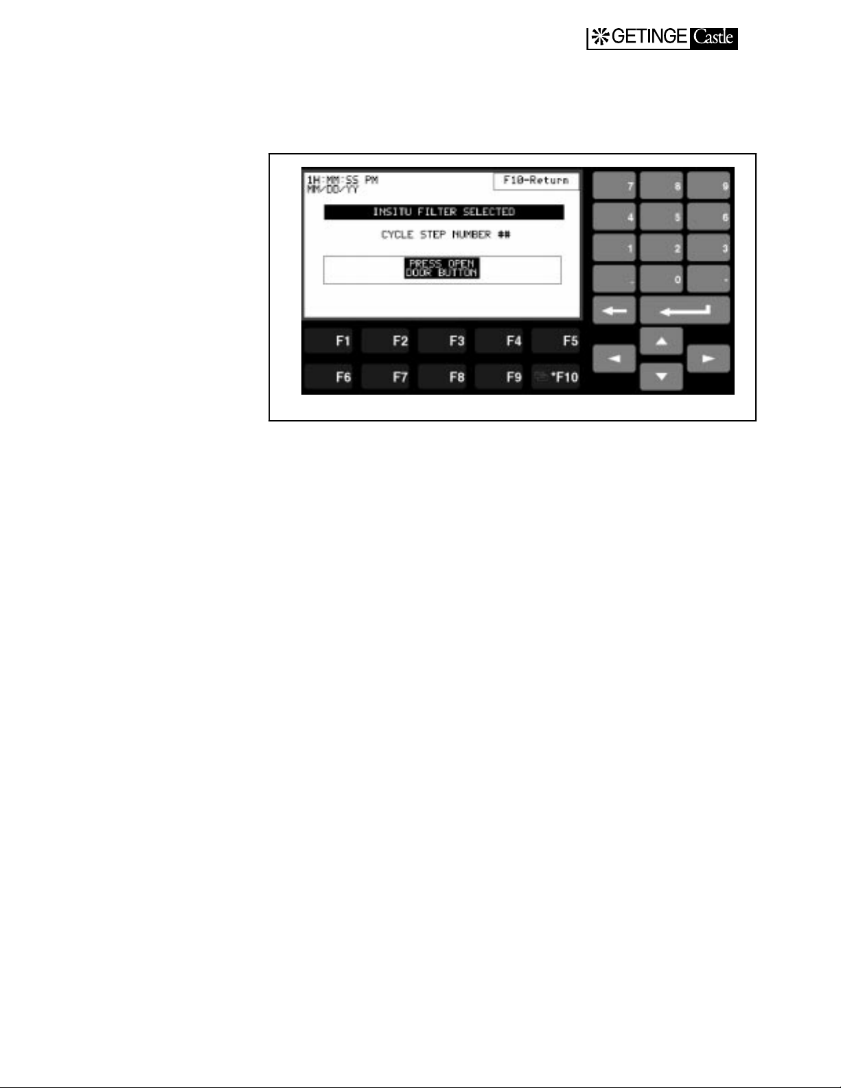
Insitu Cycle:
.
7.13
Page 44

Liquid Cycle:
.
EXIT MANUAL
Leak Test Cycle:
.
7.14
Page 45

Parameter Password Screen
In the Change Password Screen, the operator can set or change the
parameter password. To set or change the parameter password, press
F1. Enter the password by using the numbered keys followed by pressing the return key.
.
EXIT MANUAL
7.15
Page 46

Alarm Display
EXIT MANUAL
In the event an alarm condition occurs during a cycle, the Alarm display
screen will appea r. The type of alarm will be displayed in the high lighted box. Any al arm or aborte d cycle must be ackn owledged to the
control system. Acknowledge the alarm by pressing F3. The system will
then ask the operator to conti nue the cyc le or abort the cycle. Press F3
to abort the present cycle or F5 to continue the present cycle.
Emergency Stop Alarm Screen:
7.16
Page 47
System Information
The System Information display screen will identify informa tion about
the cycle progress.
EXIT MANUAL
7.17
Page 48

Service Screen
EXIT MANUAL
The Service display screen is used for service and maintenance functions such as monitoring control v alue, I/O ch ecks and man ual contr ol
of the sterilizers. The service display screen is accessed through the
main menu by the use of the up or down arrow keys followed by pressing the return key. A service password is required to access the service
display screens. Press F1 to enter the service password. Enter the password by using the numeric keys followed by pressing the return key.
In the Service display screen, the up or down arrow keys are used to
select the sterilizer components to be monitored and/or altered. Press
the return key to access the display screen s for th ese functions.
7.18
Page 49

Service Screen Passwords
In this display scree, the user can change the service password. To
change the current service password, press F1. Enter the new password
using the numeric keys followed by pressing the RETURN key to enter
the password. The system will then ask the user to verify the password.
Re-enter the password followed by pressing the RETURN key.
EXIT MANUAL
7.19
Page 50

Digital Inputs
EXIT MANUAL
In the Digital Input display, the user can observe the system’s digital
inputs as they are energized. An illuminated box ind icates that the
device is on and providing input to the controller.
.
7.20
Page 51

Digital Outputs
EXIT MANUAL
In the Digital Outpu t display, the user can manually overrid e devices,
such as opening valves, once the device is in the manual mode. For each
digital output display, the left-hand column and associated function
keys will place the selected dev ice in the manual mode when pressed.
The right-hand column and associated function keys will physically
turn the devic e on or off when p ressed. A n illumi nated bo x represe nts
the device in ON.
.
7.21
Page 52

EXIT MANUAL
7.22
Page 53

EXIT MANUAL
.
7.23
Page 54

EXIT MANUAL
.
7.24
Page 55

PID Control
EXIT MANUAL
In either the Jacket PID or the Chamber PID display screen, the user can
observe the operation of the valve which controls steam to the chamber
or jacket. The proportional ga in an d reset valu es used to maint ain temperature control can be altered fr om this display. To alter one of the
parameters, press the appropriate function key. PRess F3 to alter the
PROPORTIONAL GAIN value or F2 to alter the RESET value. Enter
the new value using the numerical keys followed by pressing the
RETURN key to enter the value.
Jacket PID
Chamber PID
7.25
Page 56

Alarm and System Messages - Troubleshooting
Note:
All alarms and system messages must be acknowledged to silence the
alarm and clear the display. Fatal errors will interru pt the cycle. The
cycle will not be interrupted whe n a non-fatal error occurs. Ackn owledging the error will not interrupt the cycle. When troubleshooting,
ALWAYS refer to the wiring diagram for the unit being serviced. Also
see the Input/Output table in the Appendix.
SERVICE TO BE PERFO RMED BY QUALIFIED PER SONNEL
ONLY.
EXIT MANUAL
7.26
Page 57

Information Text
The following messages are displayed on the display panel. Typically
the “CYCLE RESTARTED” and “CYCLE ABORTED” messages will
also be printed to the printer
CYCLE ABORT This message will be displayed if, followi ng pushing
Emergency Stop butt on and then restori ng the power, t he
operator elects to abort the current cycle by pushing the
OPEN DOOR button. S ee Emergency Stop below.
SEALING DOOR #1 This message will be d isplayed on the display panel once
all start conditions are satisfied and the start button is
pressed. When Door #1 is fully sealed, the message is no
longer displayed.
EXIT MANUAL
SEALING DOOR #2 This message will be displayed on ce all start conditions
are satisfied and the Start butt on is pressed. When Door
#2 is fully sealed, the message is no longer display ed.
UNSEALING DOOR #1 During the Cycle End phase, this me ssa ge w ill be dis-
played as the Load Door is unsealed.
UNSEALING DOOR #2 During the Cycle End phase, this me ssa ge w ill be dis-
played as the Unload Door is unsealed.
CYCLE COMPLETE During the Cycle End phase, this message will be dis-
played after the chamber has returned to atmospheri c
pressure.
CYCLE RESTARTED This message will be displa yed if, foll owing push ing the
Emergency Stop butt on and then restori ng the power, t he
operator elects to continue the cur rent cycle by pushing
the CONTINUE button on the Alarm Display. See Emergency Stop below.
UNLOADING This message will be displayed du ring the Cycle End
phase while the unload door is opened.
PRESS OPEN - LOAD This message will be displayed du ring the Cycle End
phase once the unload door has been closed again following unloading the Load Door may be opened.
OPEN DOOR This message will be displayed du ring the Cycle End
phase once the Load Door seal has been pulled and the
door is ready to be opened.
7.27
Page 58

Alarm List
EMERGENCY STOP
Message Display:
EMERGENCY STOP
This alarm is activated when the Emergency Stop pushbutton is activated from the fascia panel. All digital outputs except for the alarm and
Acknowledge Alarm lamp will be turned off. The alarm will sound and
the Acknowledge Alarm lamp will flash. It will also activate the emergency stop alarm scr een on the PanelView 9 00 operator terminal . The
alarm will be printed if the unit is in cycle.
Operator Acknowledgement:
Press the Acknowledge Alarm button to silence the alarm. The
Acknowledge Alarm lamp will stop flashing, but remain illuminated.
All outputs remain off.
EXIT MANUAL
The Emergency Stop button must be reset by inserting the key and
twisting in the clockwise direction. The cycle may be aborted or continued by pressing the appropriate button area of the touch screen display.
When a cycle is abor ted, the sterilizer will advance to the post condi tioning phase of the cycle allowing the sterilizer to advance to a safe
condition. When a cycle is continued, the process will return to the condition at the point when the alarm was activated and continue the cycle.
CHAMBER TEMPERATURE SENSOR ERROR
Alarm Condition:
The probe is out of the allowable range of -5.0
Message Display:
CHAMBER TEMP OUT OF RANGE
This alarm will turn off all digital outputs except for the alarm and
Acknowledge Alarm lamp. The alarm will sound and the Acknowledge
Alarm lamp will flash. It will also activate the alarm screen of the PanelView 900. The alarm shall be printed.
Operator Acknowledge:
o
C to 150oC
Press the Acknowledge Alarm button to silence the alarm. The
Acknowledge Alarm l amp will sto p flashi ng a nd r emain illu min ated i f
the alarm condition is still present. All outputs remain off.
The alarm must be cleared by repair or replacement of the defective
component. When the sensor returns to within the allowable range, the
process will return to the co ndition when the alarm was activ ated. The
Alarm Acknowledge lamp will extinguish.
7.28
Page 59

PRESSURE SENSOR ERROR
Alarm Condition:
The sensor is out of the allowable range of 0 PSIA to 50.0 PSIA.
Message Display:
CHAMBER PRESSURE OUT OF RANGE
This alarm will turn off all digital outputs except for the alarm and
Acknowledge Alarm lamp. The alarm will sound and the Acknowledge
Alarm lamp will flash. It will also activate the alarm screen of the PanelView 900. The alarm shall be printed.
Operator Acknowledge:
Press the Acknowledge Alarm button to silence the alarm. The
Acknowledge Alarm l amp will sto p flashi ng a nd r emain illu min ated i f
the alarm condition is still present. All outputs remain off.
The alarm must be cleared by repair or replacement of the defective
component. When the sensor returns to within the allowable range, the
process will return to the co ndition when the alarm was activ ated. The
Alarm Acknowledge lamp will extinguish.
EXIT MANUAL
INSITU FILTER TEMPERATURE SENSOR ERROR
Alarm Condition:
The probe is out of the allowable range of -5.0
Message Display:
INSITU FILTER TEMP OUT OF RANGE
This alarm will turn off all digital outputs except for the alarm and
Acknowledge Alarm lamp. The alarm will sound and the Acknowledge
Alarm lamp will flash. It will also activate the alarm screen of the PanelView 900. The alarm shall be printed.
Operator Acknowledge:
Press the Acknowledge Alarm button to silence the alarm. The
Acknowledge Alarm l amp will sto p flashi ng a nd r emain illu min ated i f
the alarm condition is still present. All outputs remain off.
The alarm must be cleared by repair or replacement of the defective
component. When the sensor returns to within the allowable range, the
process will return to the co ndition when the alarm was activ ated. The
Alarm Acknowledge lamp will extinguish.
o
C to 150oC
7.29
Page 60

LOAD TEMPERATURE SENSOR ERROR
Alarm Condition:
The probe is out of the allowable range of -5.0
Message Display:
LOAD TEMP OUT OF RANGE
This alarm will turn off all digital outputs except for the alarm and
Acknowledge Alarm lamp. The alarm will sound and the Acknowledge
Alarm lamp will flash. It will also activate the alarm screen of the PanelView 900. The alarm shall be printed.
Operator Acknowledge:
Press the Acknowledge Alarm button to silence the alarm. The
Acknowledge Alarm l amp will sto p flashi ng a nd r emain illu min ated i f
the alarm condition is still present. All outputs remain off.
The alarm must be cleared by repair or replacement of the defective
component. When the sensor returns to within the allowable range, the
process will return to the co ndition when the alarm was activ ated. The
Alarm Acknowledge lamp will extinguish.
o
C to 150oC
EXIT MANUAL
DOORS NOT CLOSED
Alarm Condition:
The door limit switch input is on.
Message Display:
DOORS NOT CLOSED
This alarm will turn off all digital outputs except for the alarm and
Acknowledge Alarm lamp. The alarm will sound and the Acknowledge
Alarm lamp will flash. It will also activate the alarm screen of the PanelView 900. The alarm shall be printed.
Operator Acknowledge:
Press the Acknowledge Alarm button to silence the alarm. The
Acknowledge Alarm l amp will sto p flashi ng a nd r emain illu min ated i f
the alarm condition is still present. All outputs remain off.
The alarm must be cleared by repair or replacement of the defective
component. When the repai r is complete, the process wi ll return to the
condition when the alarm was activated. The Alarm Acknowledge lamp
will extinguish.
7.30
Page 61

DOORS NOT SEALED
Alarm Condition:
The door seal pressure switch reads low (off) for mor e than 2 minutes.
Message Display:
DOORS NOT SEALED
The alarm will sound and the Acknowledge Alarm lamp will flash. It
will also activate the alarm screen of the PanelView 900. The alarm
shall be printed.
Operator Acknowledge:
Press the Acknowledge Alarm button to silence the alarm. The
Acknowledge Alarm l amp will sto p flashi ng a nd r emain illu min ated i f
the alarm condition is still present.
Check that required steam pressure is being supplied to the unit. The
alarm must be cleared by repair or replacement of the defective component or providing required steam pressure. When the repair is complete,
the process will return to the condition when the alarm was activated.
The Alarm Acknowledge lamp will extinguish.
EXIT MANUAL
DOORS 1 SEAL LEAK
Alarm Condition:
The door 1 seal flow switch reads high for more that 20 seconds.
Message Display:
DOORS 1 SEAL LEAK
The alarm will sound and the Acknowledge Alarm lamp will flash. It
will also activate the alarm screen of the PanelView 900. The alarm
shall be printed.
Operator Acknowledge:
Press the Acknowledge Alarm button to silence the alarm. The
Acknowledge Alarm l amp will sto p flashi ng a nd r emain illu min ated i f
the alarm condition is still present.
Check that required steam pressure is being supplied to the unit. The
alarm must be cleared by repair or replacement of the defective component or providing required steam pressure. When the repair is complete,
the process will return to the condition when the alarm was activated.
The Alarm Acknowledge lamp will extinguish.
7.31
Page 62

DOORS 2 SEAL LEAK
Alarm Condition:
The door 2 seal flow switch reads high for more that 20 seconds.
Message Display:
DOORS 2 SEAL LEAK
The alarm will sound and the Acknowledge Alarm lamp will flash. It
will also activate the alarm screen of the PanelView 900. The alarm
shall be printed.
Operator Acknowledge:
Press the Acknowledge Alarm button to silence the alarm. The
Acknowledge Alarm l amp will sto p flashi ng a nd r emain illu min ated i f
the alarm condition is still present.
Check that required steam pressure is being supplied to the unit. The
alarm must be cleared by repair or replacement of the defective component or providing required steam pressure. When the repair is complete,
the process will return to the condition when the alarm was activated.
The Alarm Acknowledge lamp will extinguish.
EXIT MANUAL
POWER FAILURE
Alarm Condition:
The processor detect there has been a loss of power.
Message Display:
POWER FAILURE
The alarm will sound and the Acknowledge Alarm lamp will flash. It
will also activate the alarm screen of the PanelView 900. The alarm
shall be printed.
Operator Acknowledge:
Press the Acknowledge Alarm button to silence the alarm. The
Acknowledge Ala rm lamp wi ll ex ti ng ui sh.
7.32
Page 63

HIGH CHAMBER PRESSURE
Alarm Condition:
The chamber pressure transducer reads greater than 60 PSIA
Message Display:
HIGH CHAMBER PRESSURE
This alarm will turn off all digital outputs except for the alarm and
Acknowledge Alarm lamp. The alarm will sound and the Acknowledge
Alarm lamp will flash. It will also activate the alarm screen of the PanelView 900. The alarm shall be printed.
Operator Acknowledge:
Press the Acknowledge Alarm button to silence the alarm. The
Acknowledge Alarm l amp will sto p flashi ng a nd r emain illu min ated i f
the alarm condition is still present. All outputs remain off.
The alarm must be cleared by repair or replacement of the defective
component. When the sensor returns to within the allowable range, the
process will return to the co ndition when the alarm was activ ated. The
Alarm Acknowledge lamp will extinguish.
EXIT MANUAL
VACUUM SYSTEM TIMEOUT
Alarm Condition:
The chamber pressure did not achiev e the necessary vacuum level
within 60 minutes.
Message Display:
VACUUM SYSTEM TIMEOUT
The alarm will sound and the Acknowledge Alarm lamp will flash. It
will also activate the alarm screen of the PanelView 900. The alarm
shall be printed.
Operator Acknowledge:
Press the Acknowledge Alarm button to silence the alarm. The
Acknowledge Alarm l amp will sto p flashi ng a nd r emain illu min ated i f
the alarm condition is still present.
The alarm must be cleared by repair or replacement of the defective
component. When the sensor returns to within the allowable range, the
process will return to the co ndition when the alarm was activ ated. The
Alarm Acknowledge lamp will extinguish.
7.33
Page 64

LOW STERILIZATION TEMPERATURE
Alarm Condition:
The controlling temperature device reads less than one degree C
o
(1.0
C) than the set sterilization temperature for more than 10 seconds.
Message Display:
LOW STERILIZATION TEMPERATURE
The alarm will sound and the Acknowledge Alarm lamp will flash. It
will also activate the alarm screen of the PanelView 900. The alarm
shall be printed.
The sterilization timer is reset t o ze r o (0:00) minutes and t he ti mer will
not restart until the temperature is regained.
Operator Acknowledge:
Press the Acknowledge Alarm button to silence the alarm. The
Acknowledge Alarm l amp will sto p flashi ng a nd r emain illu min ated i f
the alarm condition is still present.
EXIT MANUAL
The alarm will clear when the sensor returns to the set sterilization temperature. The Alarm Acknowledge lamp will extinguish.
HIGH STERILIZATION TEMPERATURE
Alarm Condition:
The controlling temperature device reads more than two degree C
o
(2.0
C) than the set sterilization temperat ure for more than 2 minutes.
Message Display:
HIGH STERILIZATION TEMPERATURE
The alarm will sound and the Acknowledge Alarm lamp will flash. It
will also activate the alarm screen of the PanelView 900. The alarm
shall be printed.
Operator Acknowledge:
Press the Acknowledge Alarm button to silence the alarm. The
Acknowledge Alarm l amp will sto p flashi ng a nd r emain illu min ated i f
the alarm condition is still present.
The alarm will clear when the sensor return s to less than two degrees
above the set sterilization tempera ture. The Alarm Ackno wledge lamp
will extinguish.
7.34
Page 65

HIGH WATER LEVEL IN DRAIN
Alarm Condition:
The drain high water level switch (LS10) is on for more than 30 seconds
Message Display:
HIGH WATER
The fast exhaust valve shall open to clear the water from the drain.
When the switch detects no water in the drain, the fast exhaust valve
will close.
The alarm will sound and the Acknowledge Alarm lamp will fla sh. It
will also activate the alarm screen of the PanelView 900. The alarm
shall be printed.
Operator Acknowledge:
Press the Acknowledge Alarm button to silence the alarm. The
Acknowledge Alarm l amp will sto p flashi ng a nd r emain illu min ated i f
the alarm condition is still present.
EXIT MANUAL
The alarm will clear when the switch detects no water in the drain. The
Alarm Acknowledge lamp will extinguish.
LEAK TEST FAILURE
Alarm Condition:
The chamber pressure rises above th e allowable leak amount. The
leak amount set point is dete rmi ned by ad ding th e chamber pre ssure at
the start of the leak test to the allow able leak amount.
Message Display:
LEAK TEST FAILURE
The alarm will sound and the Acknowledge Alarm lamp will flash. It
will also activate the alarm screen of the PanelView 900. The alarm
shall be printed and the process will automatically advance to the air
admission phase to end the cycle.
Operator Acknowledge:
Press the Acknowledge Alarm button to silence the alarm. Determine
the cause of the lead and run another lead test cycle.
7.35
Page 66

INPUT/OUTPUT LIST
EXIT MANUAL
NAME DESIGNATION
DOOR 1 NOT FULL OPEN LS1A I:1/0
DOOR 1 NOT FULL CLOSED LS1B I:1/1
DOOR 1 SAFETY SWITCH OK PS11A I:1/2
DOOR 1 SEALED PS1 I:1/3
DOOR 2 NOT FULL OPEN LS2A I:1/4
DOOR 2 NOT FULL CLOSED LS2B I:1/5
DOOR 2 SAFETY SWITCH OK PS11B I:1/6
DOOR 2 SEALED PS2 I:1/6
CHAMBER PRESSURE SWITCH PS6 I:1/7
RUPTURE DISK FAILURE PS4 I:1/8
EMERGENCY STOP PB4D1 I:1/10
HIGH DRAIN WATER LEVEL LT1 I:1/11
CONDENSER TEMP HIGH TS1 I:1/12
VACUUM PUMP TRIPPED MS3D2 I:1/13
MEMORY
LOCATION
120VAC POWER SUPPLY OK N/A I:1/14
OPEN DOOR PB200 I:2/0
CLOSE DOOR PS201 I:2/1
OPEN DOOR 2 PB202 I:2/2
CLOSE DOOR 2 PB203 I:2/3
ALARM ACKNOWLEDGE PB204 I:2/4
7.36
Page 67

Technical data
EXIT MANUAL
7.37
Page 68

EXIT MANUAL
7.38
 Loading...