

Getinge Arjohuntleigh Nimbus 3 Professional, Arjohuntleigh Nimbus 3 Instructions For Use Manual
Page 1
Product Photo
NIMBUS®3
NIMBUS
Instructions For Use
®
3 PROFESSIONAL
Page 2

Page 3

Contents
General Safety . . . . . . . . . . . . . . . . . . . . . . . . . . . . . . . . . . . . . . . . . . . . . . . . . . . . . . . iii
Introduction . . . . . . . . . . . . . . . . . . . . . . . . . . . . . . . . . . . . . . . . . . . . . . . . . . . . . . . . . 1
About this Manual . . . . . . . . . . . . . . . . . . . . . . . . . . . . . . . . . . . . . . . . . . . . . . . . . . . 1
About Nimbus 3 and Nimbus 3 Professional . . . . . . . . . . . . . . . . . . . . . . . . . . . . . . 1
Nimbus 3 Pump . . . . . . . . . . . . . . . . . . . . . . . . . . . . . . . . . . . . . . . . . . . . . . . . . . . . 2
Nimbus 3 Mattress . . . . . . . . . . . . . . . . . . . . . . . . . . . . . . . . . . . . . . . . . . . . . . . . . . 3
Nimbus 3 Professional Mattress . . . . . . . . . . . . . . . . . . . . . . . . . . . . . . . . . . . . . . . . 4
Clinical Applications . . . . . . . . . . . . . . . . . . . . . . . . . . . . . . . . . . . . . . . . . . . . . . . . . . 6
Indications . . . . . . . . . . . . . . . . . . . . . . . . . . . . . . . . . . . . . . . . . . . . . . . . . . . . . . . . . 6
Contraindications . . . . . . . . . . . . . . . . . . . . . . . . . . . . . . . . . . . . . . . . . . . . . . . . . . . 6
Cautions . . . . . . . . . . . . . . . . . . . . . . . . . . . . . . . . . . . . . . . . . . . . . . . . . . . . . . . . . . 6
Care of the patient when sitting . . . . . . . . . . . . . . . . . . . . . . . . . . . . . . . . . . . . . . . . 6
Installation . . . . . . . . . . . . . . . . . . . . . . . . . . . . . . . . . . . . . . . . . . . . . . . . . . . . . . . . . . 7
Preparing the Nimbus 3 and Nimbus 3 Professional Systems for Use . . . . . . . . . . . 7
Installing the Nimbus 3 or Nimbus 3 Professional Mattress . . . . . . . . . . . . . . . . . . . 7
Installing the Pump . . . . . . . . . . . . . . . . . . . . . . . . . . . . . . . . . . . . . . . . . . . . . . . . . . 9
Connecting the Tubeset . . . . . . . . . . . . . . . . . . . . . . . . . . . . . . . . . . . . . . . . . . . . . 10
Disconnecting the Tubeset . . . . . . . . . . . . . . . . . . . . . . . . . . . . . . . . . . . . . . . . . . . 10
System Operation . . . . . . . . . . . . . . . . . . . . . . . . . . . . . . . . . . . . . . . . . . . . . . . . . . 10
Controls, Alarms and Indicators . . . . . . . . . . . . . . . . . . . . . . . . . . . . . . . . . . . . . . . 11
Pump Controls . . . . . . . . . . . . . . . . . . . . . . . . . . . . . . . . . . . . . . . . . . . . . . . . . . . . 11
Pump Indicators . . . . . . . . . . . . . . . . . . . . . . . . . . . . . . . . . . . . . . . . . . . . . . . . . . . 12
Mattress Controls . . . . . . . . . . . . . . . . . . . . . . . . . . . . . . . . . . . . . . . . . . . . . . . . . . 14
Additional Controls on the Nimbus 3 Professional Mattress . . . . . . . . . . . . . . . . . . 14
Operation . . . . . . . . . . . . . . . . . . . . . . . . . . . . . . . . . . . . . . . . . . . . . . . . . . . . . . . . . . 16
Installing the System . . . . . . . . . . . . . . . . . . . . . . . . . . . . . . . . . . . . . . . . . . . . . . . . 16
Inflating the Mattress . . . . . . . . . . . . . . . . . . . . . . . . . . . . . . . . . . . . . . . . . . . . . . . . 16
Testing the Power Fail Alarm . . . . . . . . . . . . . . . . . . . . . . . . . . . . . . . . . . . . . . . . . 16
Deflating the Mattress . . . . . . . . . . . . . . . . . . . . . . . . . . . . . . . . . . . . . . . . . . . . . . . 17
System Optimisation . . . . . . . . . . . . . . . . . . . . . . . . . . . . . . . . . . . . . . . . . . . . . . . . 18
Selecting the Operating Mode . . . . . . . . . . . . . . . . . . . . . . . . . . . . . . . . . . . . . . . . 18
Silencing Audible Alarms . . . . . . . . . . . . . . . . . . . . . . . . . . . . . . . . . . . . . . . . . . . . 19
Comfort Control . . . . . . . . . . . . . . . . . . . . . . . . . . . . . . . . . . . . . . . . . . . . . . . . . . . . 19
Transport Control . . . . . . . . . . . . . . . . . . . . . . . . . . . . . . . . . . . . . . . . . . . . . . . . . . 19
CPR Control . . . . . . . . . . . . . . . . . . . . . . . . . . . . . . . . . . . . . . . . . . . . . . . . . . . . . . 20
Patient Positioning Guidance for the Nimbus 3 Professional Mattress . . . . . . . . . . 21
Decontamination . . . . . . . . . . . . . . . . . . . . . . . . . . . . . . . . . . . . . . . . . . . . . . . . . . . . 23
Routine Maintenance . . . . . . . . . . . . . . . . . . . . . . . . . . . . . . . . . . . . . . . . . . . . . . . . 25
Nimbus 3 and Nimbus 3 Professional Systems . . . . . . . . . . . . . . . . . . . . . . . . . . . 25
Nimbus 3 Pump . . . . . . . . . . . . . . . . . . . . . . . . . . . . . . . . . . . . . . . . . . . . . . . . . . . 25
Nimbus 3 and Nimbus 3 Professional Mattresses . . . . . . . . . . . . . . . . . . . . . . . . . 25
(i)
Page 4

Serial Number Labels . . . . . . . . . . . . . . . . . . . . . . . . . . . . . . . . . . . . . . . . . . . . . . . 26
Troubleshooting . . . . . . . . . . . . . . . . . . . . . . . . . . . . . . . . . . . . . . . . . . . . . . . . . . . . 27
Technical Description . . . . . . . . . . . . . . . . . . . . . . . . . . . . . . . . . . . . . . . . . . . . . . . . 28
Pump . . . . . . . . . . . . . . . . . . . . . . . . . . . . . . . . . . . . . . . . . . . . . . . . . . . . . . . . . . . . 28
Accessories . . . . . . . . . . . . . . . . . . . . . . . . . . . . . . . . . . . . . . . . . . . . . . . . . . . . . . . 29
Mattress . . . . . . . . . . . . . . . . . . . . . . . . . . . . . . . . . . . . . . . . . . . . . . . . . . . . . . . . . 29
Cover Specification . . . . . . . . . . . . . . . . . . . . . . . . . . . . . . . . . . . . . . . . . . . . . . . . . 30
Cleaning Symbols . . . . . . . . . . . . . . . . . . . . . . . . . . . . . . . . . . . . . . . . . . . . . . . . . . 31
(ii)
Page 5

GENERAL SAFETY
Before you connect the system pump to a mains socket, read carefully all the installation
instructions contained within this manual.
The system has been designed to comply with regulatory safety standards including:
• EN60601-1:1990/A13:1996 and IEC 60601-1:1988/A2:1995
• UL60601-1, UL2601-1 and CAN/CSA C22.2 No. 601.1-M90
Safety Warnings
• It is the responsibility of the care giver to ensure that the user can use this product
safely.
• Whilst the patient is unattended, safety sides should be used based on clinical
assessment and in line with local policy.
• Alignment of the bed frame, safety sides and the mattress should leave no gap
wide enough to entrap a patient's head or body, or to allow egress to occur in a
hazardous manner where entanglement with the mains power cable and tubeset or
air hoses may result. Care should be exercised to prevent occurrence of gaps by
compression or movement of the mattress. Death or serious injury may occur.
• Make sure that the mains power cable and tubeset or air hoses are positioned to
avoid causing a trip or other hazard, and are clear of moving bed mechanisms or
other possible entrapment areas. Where cable management flaps are provided
along the sides of the mattress, these should be used to cover the mains power
cable.
• Electrical equipment may be hazardous if misused. There are no user-serviceable
parts inside the pump. The pump's case must only be removed by authorised
technical personnel. No modification of this equipment is allowed.
• The mains power socket/plug must be accessible at all times. To disconnect the
pump completely from the electricity supply, remove the plug from the mains
power socket.
• The CPR control and/or the CPR indicator tag must be visible and accessible at all
times.
• Disconnect the pump from the mains power socket before cleaning and inspecting.
• Keep the pump away from sources of liquids and do not immerse in water.
• Do not use the pump in the presence of uncontained flammable liquids or gasses.
• The cover of this product is vapour permeable but not air permeable and may
present a suffocation risk.
• Only the pump and mattress combination as indicated by ArjoHuntleigh should be
used. The correct function of the product cannot be guaranteed if incorrect pump
and mattress combinations are used.
• To avoid the risk of electric shock, this equipment must only be connected to a
supply mains with protective earth.
• Due to the inherently lower flame retardancy of the high performance eVENT
®1
fabric, it is NOT suitable for use in the homecare environment.
Precautions
For your own safety and the safety of the equipment, always take the following
precautions:
1. eVENT® is a registered trademark of BHA Technologies Inc.
(iii)
Page 6

• Placing extra layers between the patient and the mattress potentially reduces the benefit s
provided by the mattress and sh ould be avoid ed or kept to a minimum. As p art of sens ible
pressure area care, it is advisable to avoid wearing clothing which may cause areas of
localised high pressure due to creases, seams, etc. Placing objects in pockets should be
avoided for the same reason.
• Do not expose the system, especially the mattress, to naked flames, such as cigarettes,
etc.
• In the event of a fire, a leak in the seat or mattress could propagate the fire.
• Do not store the system in direct sunlight.
• Do not use phenol-based solutions to clean the system.
• Make sure the system is clean and dry prior to use or storage.
• Never use sharp objects or electrically heated under blankets on or under the system.
• Store the pump and mattress in the protective bags supplied.
Electromagnetic Compatibility (EMC)
This product complies with the requiremen ts of applicable EMC Standa rds. Medical ele ctrical
equipment needs special precautions regarding EMC and needs to be installed in accordance
with the following instructions:
• The use of accessories not specified by the manufacturer may result in increased
emissions by, or decreased immunity of, the equipment, affecting its performance.
• Portable and mobile radio frequency (RF) communications equipment (e.g. mobile/cell
phones) can affect medical electrical equipment.
• If this equipment needs to be used adjacent to other electrical equipment, normal
operation must be checked before use.
• For detailed EMC information contact ArjoHuntleigh service personnel.
Environmental Protection
Incorrect disposal of this equipment and its component parts, particularly batt eries or other
electrical components, may produce substances that are hazardous to the environment. To
minimise these hazards, contact ArjoHuntleigh for information on correct disposal.
Service Information
ArjoHuntleigh recommend that th is system sh ou ld b e se rviced e ver y 12 ca le nd ar m on th s or,
where applicable, when the service indicator is illuminated.
Design Policy and Copyright
® and ™ are trademarks belonging to the ArjoHu ntleigh g roup of co mpanies. As our pol icy is
one of continuous improvement, we reserve the right to modify designs without prior notice.
© ArjoHuntleigh 2009.
(iv)
Page 7

1. Introduction
About this Manual This manual is your introduction to the Nimbus
Nimbus 3 Professional systems. Use it to initially set up
the system, and keep it as a reference for day-to-day
routines and as a guide to maintenance.
About Nimbus 3 and Nimbus 3 Professional
Nimbus 3 and Nimbus 3 Professional are Dynamic
Flotation Systems for the prevention, treatment and
management of pressure ulcers.
Nimbus 3 and Nimbus 3 Professional systems comprise
a pump and mattress replacement which can be used on
standard hospital and normal domestic beds. Beds can
be adjusted or profiled with the mattress in position.
Nimbus 3 Professional mattress has the following
The
additional features to enable the patient to be proned,
and to assist with pressure area and patient care
management:
• A Head Section Deflate Control to allow the three
head cells to be fully deflated.
®
3 and
• Individual Vent Valves to allow 16 of the 20 cells to
be independently deflated.
Nimbus 3 and Nimbus 3 Professional mattresses
The
incorporate an advanced
AutoMatt® sensor pad which
makes sure that the patient is automatically supported at
optimum pressures regardless of size, height, position or
weight distribution.
If cardiac arrest occurs, the
Professional mattresses can be deflated in less than 10
Nimbus 3 and Nimbus 3
seconds to allow cardiac resuscitation procedures to be
performed.
Caution
Federal law restricts this device to sale by or on the order of a
physician.
1
Page 8
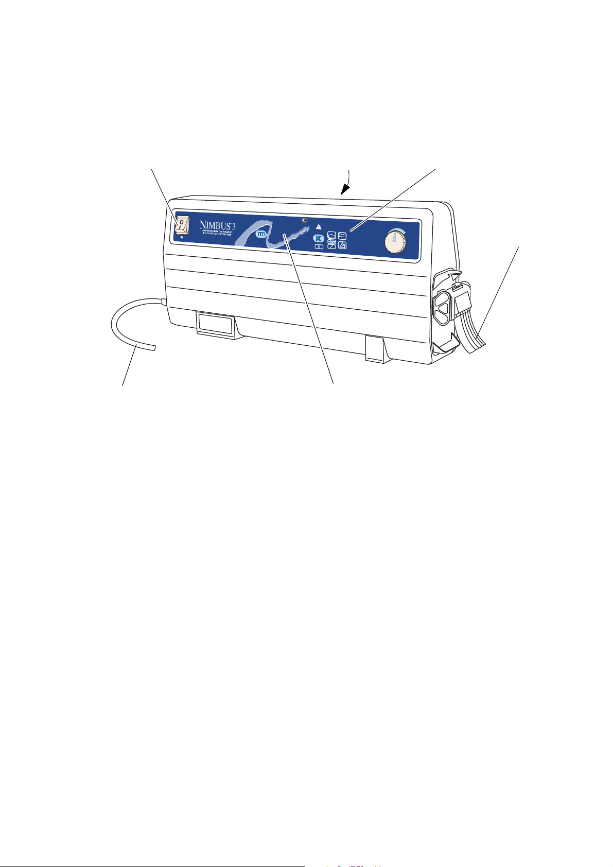
Nimbus 3 Pump The same pump is used on the
Hi
mmHg
Lo
mmHg
-
+
mmHg
Front Panel
Mains Power Switch Alarm Indicators
Tubeset
Mains Power Cord
Carry Handle
Professional systems.
The pump comprises a moulded case with non-slip feet
on the base and rear, and an integral carry handle.
Nimbus 3 and Nimbus 3
The pump has two modes of operation:
•
Dynamic mode that cycles the support surface
beneath the patient every 10 minutes providing
periods of pressure relief for the whole body.
Static mode where the support surface remains
•
constant (all cells equally inflated).
The controls and indicators are located on the front
panel, and a sophisticated alarm system differentiates
between normal operation and genuine system faults. If
an alarm situation is detected a flashing indicator will
illuminate, together with an indication of the cause of
alarm, and an audible warning will sound.
The pump can be fixed to the foot end of a hospital bed
by the separate bed bracket. The bed bracket fits in the
pump handle and then clips onto most common bed
frames. The pump can also be stood on the floor, either
upright or on its rear cover.
2
Page 9
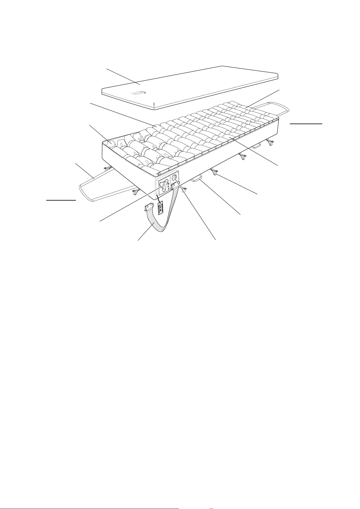
Nimbus 3 Mattress The
CPRCPR
1
3
N
O
R
M
A
L
NORMAL
T
R
A
N
S
P
O
R
T
TRANSPORT
2
FAS
T
D
E
F
L
A
T
E
FASTDEFLATE
Detachable Cover
CPR Control
Transport Control
Carry Handle
Securing Strap
Pump Tubeset
5 “Heelguard” Cells
3 Head Cells
8 Torso Cells
4 Thigh Cells
Head End
Foot End
Drag Handle
components:
Nimbus 3 mattress comprises the following
Detachable Cover The standard protective cover comprises a 2-way stretch
cover zipped to a durable anti-slip base. The zips are
protected by flaps to prevent ingress of contaminants,
and allow easy removal of the cover for cleaning.
Alternative covers with advanced properties, such as
®
Advantex
and eVENT®, are also available (Refer to
“Cover Specification” on page 30).
Cells The Nimbus 3 mattress comprises 20 polyurethane (PU)
cells providing support to the user in either Alternating
or Static modes. The cells are grouped in four sections,
each of which has a specific function:
• The three Head cells remain at a constant pressure
for pillow stability and patient comfort.
• The eight Torso cells combine alternating and static
pressure characteristics to support patients fully in
both lying and sitting positions without the risk of
‘bottoming’.
• The four Thigh cells cycle dynamically to maximise
pressure relief.
• The five
Heelguard
maximise the pressure relief under the heels.
®
cells are specially powered to
3
Page 10
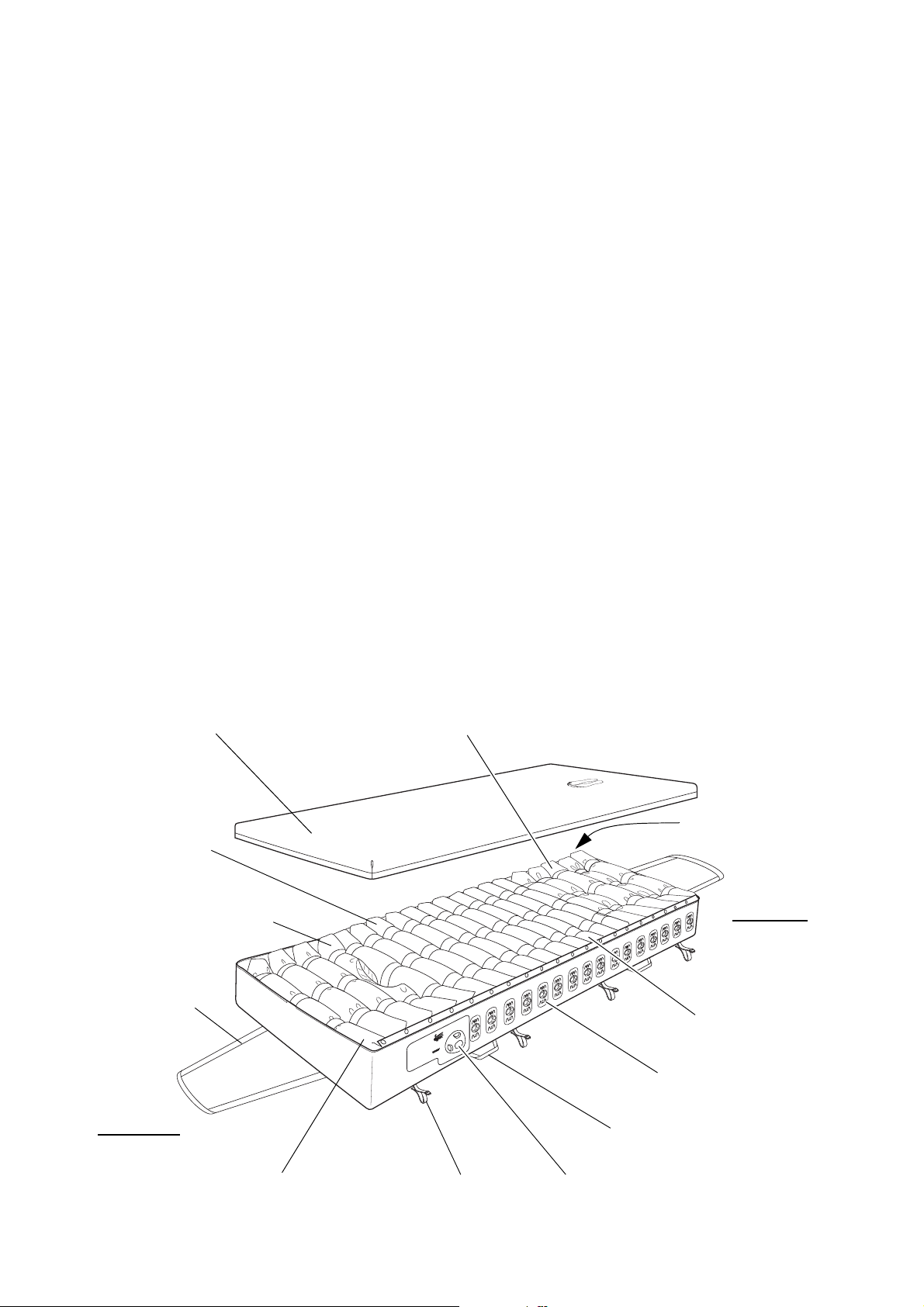
AutoMatt The advanced AutoMatt sensor pad is under the cells,
Detachable Cover
CPR/Transport
Shoulder Support Cell
Carry Handle
Securing Strap
5 “Heelguard” Cells
3 Head Section Cells
7 Torso Cells
4 Thigh Cells
Head End
Foot End
16 Vent Valves
Head Section Deflate Control
Control
Drag Handle
(with Central Cutout)
(“Power-Down” Cells)
and makes sure that the patient is automatically
supported at optimum pressures regardless of size,
height, position or weight distribution.
CPR Control The CPR (Cardio-Pulmonary Resuscitation) Control is
at the foot end of the mattress, and allows the air to be
evacuated in under 10 seconds.
Transport Control The Transport Control is next to the CPR Control. When
operated, it seals the mattress so that air is not exhausted
when the tubeset is disconnected and also creates an
even pressure in all the cells.
Tubeset The tubeset incorporates a flexible, compact anti-kink
tube that is resistant to crushing and any subsequent
obstruction of air flow. Each end has a quick-lock
system for easily connecting and disconnecting the air
supply at the pump and mattress.
Nimbus 3 Professional Mattress
Nimbus 3 Professional mattress is of similar
The
construction to the
Nimbus 3 mattress, with the addition
of a Head Section Deflate Control, individual Vent
Valves on 16 of the 20 cells and a Shoulder Support
Cell.
4
Page 11

Head Section Deflate
Control
Cells The Nimbus 3 Professional mattress has the same
This is a two-position rotary-action control at the head
end of the mattress:
• Dynamic (Normal) Mode. The three cells in the Head
Section are inflated at a constant pressure and the
remaining 17 cells alternate.
T riCell Head Section Deflate. The three cells in the
•
Head Section are fully deflated to assist with patient
care management, and the Shoulder Support Cell (the
fourth cell, next to the Head Section) is inflated to a
constant pressure to support the patient’s shoulders.
The remaining 16 cells alternate.
number of cells as the
Nimbus 3 mattress (20 cells). The
function of the first four cells at the head end of the
mattress is different on the
Nimbus 3 Professional:
• The three cells in the Head Section are either fully
inflated or fully deflated, depending on the position
of the Head Deflate Control, to assist with patient
care management. The cells are specially powered to
enable them to be fully deflated.
• The single Shoulder Support Cell (the fourth cell,
next to the Head Section) has a shallow cutout in the
mid-section of the cell. This is to allow access to the
neck area for clinical procedures and to ensure the
smooth, uniform extension of the neck during
deflation. Its operation is controlled by the Head
Section Deflate Control: the cell is either fully
inflated to support the patient’s shoulders or
alternates (together with the remaining 16 cells).
• The remaining 16 cells (seven T orso cells, four Thigh
cells and five
function as on the
Vent Valves The seven Torso cells, four Thigh cells and five
Heelguard cells have individual Vent Valves to allow
Heelguard cells) have the same basic
Nimbus 3 mattress.
each cell to be independently deflated, to assist with
pressure area and patient care management.
5
Page 12

2. Clinical Applications
Indications The Nimbus 3 and Nimbus 3 Professional systems are
indicated for the prevention and management of all
categories1 of pressure ulcer when combined with an
individualised monitoring, repositioning and wound care
programme.
The
designed for patients weighing up to 250 kg (550 lb).
The
designed for patients weighing up to
Nimbus 3 and Nimbus 3 Professional mattress is
Nimbus 3 and Nimbus 3 Professional cushion is
250 kg (550 lb).
Contraindications Do not use
for patients with unstable spinal fractures.
Cautions If patients have other unstable fractures, or conditions
which may be complicated by a soft or moving surface,
advice should be sought from an appropriate clinician
before use.
While the
have been designed to manage patients up to the weight
limits indicated above, those approaching this upper limit
are likely to have additional care and mobility needs and
may be better suited to a specialist bariatric system.
Active therapy (alternating) cushions may be unsuitable
for patients with poor sitting posture or pelvic deformity;
advice from a seating specialist should be sought.
Care of the patient
when sitting
Seated patients are at increased risk of pressure ulcers
particularly if they are immobile or have wounds over the
seating area. For optimal outcome, provide a pressure
redistributing seat cushion in a chair which promotes a
good sitting posture and has a level base seat to support the
cushion, in addition to an individualised repositioning
programme.
Nimbus 3 and Nimbus 3 Professional systems
Nimbus 3 and Nimbus 3 Professional systems
The above are guidelines only and should not replace clinical judgement.
The
Nimbus 3 and Nimbus 3 Professional systems represent one aspect of a
pressure ulcer management strategy; if existing wounds do not improve or the
patients condition changes the overall therapy regimen should be reviewed by
the prescribing clinician.
Mattress and cushion combinations may have different upper weight limits.
Cushions should be used in combination with pressure-redistributing
mattresses to provide 24-hour therapy.
1. NPUAP/EPUAP International Pressure Ulcer Guideline, 2009.
6
Page 13

3. Installation
The Nimbus 3 and Nimbus 3 Professional systems are very simple to install
using the following guidelines.
Refer to Section 4, Page 11 “Controls, Alarms and Indicators” for a
comprehensive description of the controls and indicators on the pump and
mattress.
Preparing the Nimbus 3 and Nimbus 3 Professional Systems for Use
1. Remove the system from the packaging. You
should have the following items:
Nimbus 3 pump, with integral mains power cord.
•
•
Nimbus 3 mattress replacement or the
Nimbus 3 Professional mattress replacement.
• Bed bracket.
•Tubeset.
Installing the Nimbus 3 or Nimbus 3 Professional Mattress
1. Remove the conventional mattress from the bed
frame and check that there are no protruding bed
springs or sharp objects on the bed frame surface.
Heavily ridged bed baseboards may require special considerations for
correct system operation - consult your ArjoHuntleigh representative.
2. Unroll the mattress onto the bed base and make
sure that the CPR is at the foot end, and the CPR
label is hanging freely.
3. Attach the mattress to the bed frame using the hook
and loop securing straps.
If the bed can be profiled to any position (i.e. raised or lowered), attach the
mattress to the movable parts of the bed only.
7
Page 14

4. For
C
P
R
1
3
N
O
R
M
A
L
T
R
A
N
S
P
O
R
T
2
FA
S
T
D
E
F
L
A
T
E
Head End
Foot End
Soft Foam Sheet
Hard Foam Sheet
AutoMatt
Sensor Pad
Cover
Cells
Hard Foam Sheet
AutoMatt Sensor Pad
CPR
1
3
NORMAL
TRANSPORT
2
FAST DEFLATE
Transport ControlCPR Control
NORMAL
TRANSPORT
Nimbus 3 mattresses only, check the AutoMatt
sensor pad, as follows:
• Unzip the cover on one side of the mattress only.
• Pull the side of the mattress away from the cells.
•The
AutoMatt sensor pad is situated under the cells
between the soft and hard foam sheets.
• Make sure that the
AutoMatt sensor pad is lying
flat and is not “kinked”.
• Zip the cover back onto the mattress, taking care
not to trap any cell material in the zip.
For Nimbus 3 Professional mattresses, the AutoMatt is encapsulated and
does not need to be checked.
5. Leave the ends of the mattress cover free when
profiling the bed.
6. Make sure the CPR control is closed and locked in
position and the Transport control is set to
NORMAL.
8
Page 15

Additional Checks on
Closed
Open
Dynamic (Normal) Mode
TriCell Head Section Deflate
the Nimbus 3
Professional Mattress
1. Make sure that all 16 Vent Valves are closed.
2. Make sure that the Head Section Deflate Control is
set to
Dynamic (Normal) Mode.
Installing the Pump 1. If the pump is to be hung from the end of the bed,
make sure that the bed bracket is securely attached
to the pump, and then attach the pump and bed
bracket to the bed frame.
2. Alternatively the pump can be placed underneath
the bed, either upright or lying on its back.
3. Insert the connector on the end of the mains power
cord into a suitable mains power outlet.
9
Page 16

Connecting the
1
2
1
2
Tubeset
To connect the tubeset to the mattress and pump:
1. Locate the bottom of the tubeset connector onto the
bottom of the pump/mattress connector.
2. Pull the top of the tubeset connector up and over the
top of the pump/mattress connector, until the
tubeset connector “clicks” into position.
3. Make sure both connections are secure.
Disconnecting the
Tubeset
To disconnect the tubeset from the mattress and pump:
1. Move the tubeset connector down by pulling the
tubeset extrusion downwards, and then pull the
bottom of the tubeset connector away from the
bottom of the pump/mattress connector.
2. Lift the top of the tubeset connector off the top of
the pump/mattress connector.
System Operation The system is now ready for use. Refer to
Section 4, Page 11 “Controls, Alarms and Indicators”
and Section 5, Page 16 “Operation” for day-to-day
operating instructions.
WARNING
Make sure the mains power cord and tubeset are positioned to
avoid causing a hazard.
Caution
Make sure the mains power cord and tubeset are clear of moving
bed mechanisms or other possible entrapment areas.
10
Page 17

4. Controls, Alarms and Indicators
-
+
mmHg
Hi
mmHg
Lo
mmHg
N
R
Power Switch Mute Control
Static Control
ComfortWait
High Pressure
Indicator
Low Pressure
Indicator
Power Fail
Indicator
Service
Indicator ControlIndicator
& Alarm Reset & Indicator
& Indicator
Pump Fault
Indicator
Alarm
Indicator
On/Reset Alarm
Indicator
mmHg
+
Pump Controls The pump front panel has the following controls:
POWER Switch (and
RESET ALARM)
STATIC Mode Selects the operating mode, either Static or Dynamic.
Alarm MUTE An audible alarm mute is provided to cancel warning
Switches the mains power to the pump on and off.
The green indicator is illuminated when the mains
power is connected and the pump switched on.
The switch is also used to reset the pump after an alarm
condition has been detected.
Static mode is confirmed when the yellow indicator on
the button is illuminated.
When Dynamic mode (default) is selected the yellow
indicator will be extinguished.
sounds during an alarm condition.
COMFORT CONTROL This is a rotary action control to set the relative firmness/
softness of the mattress for patient comfort.
11
Page 18

Pump Indicators The pump front panel has the following indicators:
Hi
mmHg
Lo
mmHg
ON / RESET ALARM The green ON / RESET ALARM indicator below the
POWER switch is illuminated when the mains power is
connected and the pump switched on.
STATIC Mode The indicator on the STATIC button is illuminated when
Static mode has been selected for operation.
Alarm MUTE The indicator on the MUTE button is illuminated when
an audible alarm has been silenced.
The indicator will NOT be illuminated when a Power Fail alarm is muted.
WAIT The WAIT indicator is illuminated when the mattress is
being inflated.
The indicator will remain illuminated until the mattress
has been fully inflated. This may take up to 15 minutes.
HIGH PRESSURE The HIGH PRESSURE indicator is illuminated whenever
the pump detects high pressure within the mattress.
If this condition occurs, the air supply from the pump is
switched off until normal pressure is detected. After 2
seconds of normal pressure being detected the indicator
is switched off and the air supply restarted.
LOW PRESSURE The LOW PRESSURE indicator is illuminated whenever
the pump detects low pressure within the mattress.
This may indicate that there is insufficient pressure to
support a patient or that the Transport control is turned
to the
TRANSPORT position whilst the pump is on and
connected to the mattress.
The LOW PRESSURE indicator will be switched off
once normal pressure is reached.
Alarm The pump unit incorporates a sophisticated alarm
detection system that differentiates between patient
movement and genuine alarm conditions.
Whenever an alarm condition is detected the red
Alarm
triangle starts flashing together with an indicator of the
cause of the alarm. Additionally, an audible warning
will sound, which can be cancelled by pressing the
Alarm MUTE button (Refer to “Alarm MUTE” on
page 11).
The triangular Alarm symbol is displayed with one or
more of the following indicators:
12
Page 19

• LOW PRESSURE (Refer to “LOW PRESSURE” on
page 12).
• HIGH PRESSURE (Refer to “HIGH PRESSURE” on
page 12).
•PUMP FAULT (Refer to “PUMP FAULT” on
page 13).
•
POWER (Refer to “POWER Fail” on page 13).
For all alarm conditions except Power Fail, once the alarm condition has
been detected and displayed, it can only be cancelled by switching the pump
unit off and then back on.
Refer to Section 8, Page 27 “Troubleshooting” for
possible causes of the above alarm conditions.
PUMP FAULT The PUMP FAULT indicator is illuminated when an
internal pump malfunction is detected.
The fault can only be rectified by carrying out a service
on the pump.
POWER Fail The POWER indicator will flash when a mains power
failure has been detected.
The alarm will continue until the mains power is
resumed or the pump is switched off using the
POWER
switch on the pump control panel.
Service Indicator The symbol will be illuminated after a set number of
running hours to indicate that the pump is ready for a
service.
This service period is set to 12 months.
The pump will continue to operate normally even when the symbol is
illuminated.
13
Page 20

Mattress Controls All
CPR
1
3
NORMAL
TRANSPORT
2
FAST DEFLATE
Transport ControlCPR Control
NORMAL
TRANSPORT
Nimbus 3 and Nimbus 3 Professional mattresses
have the following two controls, situated at the foot end
of the mattress:
Transport Control This sets the mattress into TRANSPORT mode where the
support surface is equally pressurised and the pump and
tubeset can be removed. In this mode the mattress will
support the patient for up to 12 hours.
CPR Control The CPR (Cardio-Pulmonary Resuscitation) Control
provides a means of rapidly deflating the mattress to
allow normal resuscitation procedures to be carried out.
The CPR control is used to deflate the mattress for packing and storage.
Additional Controls on the Nimbus 3 Professional Mattress
The following two controls are on the opposite side of
the mattress to the CPR/Transport Control:
Head Section Deflate
Control
This is a two-position rotary-action control at the head
end of the mattress:
Dynamic (Normal) Mode. The three cells in the Head
•
Section are inflated at a constant pressure and the
remaining 17 cells alternate.
TriCell Head Section Deflate. The three cells in the
•
Head Section are fully deflated to assist with patient
care management, and the Shoulder Support Cell
(next to the Head Section) is inflated to a constant
14
Page 21

pressure to support the patient’s shoulders. The
Dynamic (Normal) Mode
TriCell Head Section Deflate
Closed
Open
remaining 16 cells alternate.
16 Vent Valves The seven Torso cells, four Thigh cells and five
Heelguard cells have individual Vent Valves to allow
each cell to be independently deflated, to assist with
pressure area and patient care management.
15
Page 22

5. Operation
These instructions cover day-to-day operation of the system. Other operations, such
as maintenance and repair, should only be carried out by suitably qualified
personnel.
Refer to Section 4, Page 11 “Controls, Alarms and Indicators” for a
comprehensive description of the controls and indicators on the pump and
mattress.
Installing the System Before using the
system make sure:
1. The system has been installed correctly in
accordance with Section 3, Page 7 “Installation”.
2. The CPR unit on the mattress is closed and locked
in position.
3. The Transport control on the mattress is set to
NORMAL.
4. If a Nimbus 3 Professional system is being
installed, make sure that on the mattress:
• All 16 Vent Valves are closed.
• The Head Section Deflate Control is set to
Dynamic (Normal) Mode.
Inflating the Mattress 1. Switch the pump POWER switch to ON.
ON / RESET ALARM indicator below the
The
POWER switch should illuminate.
2. The pump will now run a self test for
approximately 3 seconds when all the indicators on
the front panel will be illuminated.
Nimbus 3 or Nimbus 3 Professional
3. If the pump detects low pressure (e.g. a deflated
mattress) it will enter an inflation sequence with the
LOW PRESSURE and WAIT indicators illuminated.
4. Once normal operating pressure has been reached
both the
extinguish.
LOW PRESSURE and WAIT lights will
It may take up to 15 minutes to inflate the mattress.
The three Head Section cells and the five Heelguard cells will inflate more
slowly than the rest of the mattress.
Testing the Power
Fail Alarm
The Power Fail Alarm is powered by a rechargeable
battery. The duration of the alarm will depend on the
level of charge in the battery.
16
Page 23

The battery may have become discharged or reached the
end of its life. It is therefore recommended that the alarm
is tested before the pump is used, as follows.
1. Connect the pump to the mains power supply,
switch
2. Remove the mains power at the wall socket without
switching the pump off.
3. The power fail alarm should operate within 10
seconds, as follows:
ON and allow it to run for 10-15 seconds.
• The red
•The
• An audible warning will sound.
4. The alarm will continue until the mains power is
resumed or the pump is switched off using the
POWER switch on the pump control panel.
5. If the alarm does not operate, run the pump for
approximately four hours to recharge the battery.
6. Retest the alarm after the battery has been
recharged. Allow the alarm to operate for
approximately two minutes to ensure that it has
been adequately recharged.
7. If the alarm does not operate for two minutes, call
the service engineer.
Alarm triangle will flash.
POWER indicator will flash.
If the Power Fail Alarm does not operate after this test and a service
engineer has been called, the pump can continue to be used with regular
checks of the Power-On status.
All other alarms will continue to function as normal.
Deflating the
Mattress
To deflate and store the mattress, do the following:
1. Switch off the pump, and disconnect the pump from
the mains power supply.
2. Remove the tubeset from the pump and mattress
(Refer to “Disconnecting the Tubeset” on page 10).
3. Activate the CPR control.
4. Make sure the Transport control is set to
5. Roll up the mattress, starting at the foot end.
Make sure the mattress is dry before rolling it up.
17
NORMAL.
Page 24

System Optimisation The
Nimbus 3 and Nimbus 3 Professional systems
automatically compensate for patient weight
distribution and position, to optimise the pressure
relieving performance.
To make sure that the pressure relieving properties are not impaired, the
mattress cover must not be pulled tight and covering sheets should fit loosely
using the attached clips.
The system provides two modes of operation:
•
Dynamic mode provides the optimum pressure
relieving performance and should be used in most
cases. In
the patient is cycled every 10 minutes.
Static mode provides a stable, non-moving support
•
surface for instances where a dynamic support
surface is contra-indicated. In
support surface remains constant (all cells are
equally inflated).
Dynamic mode the support surface beneath
Static mode the
Nimbus 3 Professional
Mattress only
On the Nimbus 3 Professional system, the following
therapeutic positioning controls along the side of the
mattress offer further operating modes in combination
with the
Dynamic pressure relief option, to assist with
pressure area and patient care management:
1. Head Section Deflate Control. This controls the
three cells in the Head Section:
Dynamic (Normal) Mode, where the three Head
•
cells are inflated at a constant pressure and the
remaining 17 cells alternate.
T riCell Head Section Deflate, where the three Head
•
cells are fully deflated, and the Shoulder Support
Cell is inflated to a constant pressure to support
the patient’s shoulders. The remaining 16 cells
alternate.
2. 16 Vent Valves.
The seven Torso cells, four Thigh cells and five
Heelguard cells have individual Vent Valves to
allow each cell to be independently deflated.
Selecting the
Operating Mode
• The pump defaults to the
when switched on.
• Both
selected by the
• When
STATIC button illuminates.
Static and Dynamic modes of operation are
STATIC button on the front panel.
Static mode is selected the indicator on the
18
Dynamic operating mode
Page 25

To change the operating mode:
1. T o select
STATIC button once. An audible tone will sound
Static mode from Dynamic mode press the
and the indicator on the button will illuminate to
show that the system is in
2. T o select
STATIC button once. An audible tone will sound
Dynamic mode from Static mode press the
Static mode.
and the indicator on the button will extinguish.
Silencing Audible
Alarms
Audible alarms can be silenced using the
To silence an alarm push the
indicator on the
MUTE button will remain illuminated).
MUTE button once (the
MUTE button.
In its normal operating mode an audible alarm can only be silenced after an
alarm has occurred. An internal setting can be used to change the mode of
operation so that this button can pre-silence an alarm. Call your service
engineer if this option is required.
Comfort Control The mattress cell pressure can be manually adjusted for
patient comfort using the rotary
To change the comfort setting:
COMFORT CONTROL.
• Turn COMFORT CONTROL clockwise for a firmer
setting and counterclockwise for a softer setting.
• The mattress minimum pressure is maintained at the
chosen level.
The system automatically compensates for patient size, height, position and
weight distribution to provide optimum support regardless of the
CONTROL setting.
Transport Control This seals the mattress and allows the removal of the
pump for patient transport. The patient will remain
supported by the mattress for up to 12 hours in
mode. To set the
Transport mode:
1. At the foot end of the mattress turn the Transport
control knob clockwise to TRANSPORT.
2. Turn the pump off and disconnect the tubeset.
COMFORT
Transport
If the Transport control is set to TRANSPORT with the tubeset connected and
the pump switched on, then the pump will indicate a
alarm.
Low Pressure fault
To resume normal operation:
1. Re-connect the pump and tubeset to the mattress.
2. Turn the Transport control knob counterclockwise
NORMAL.
to
19
Page 26

CPR Control
CPR
1
3
NORMAL
TRANSPORT
2
FAST DEFLATE
CPR
1
3
NORMAL
TRANSPORT
2
FAST DEFLATE
1
3
NORMAL
TRANSPORT
2
FAST DEFLATE
CPR
IMPORTANT
IN THE EVENT OF CARDIAC ARREST.
In the event of a patient suffering cardiac arrest and CPR
needing to be administered:
To Activate the CPR 1. Lift the red CPR handle at the foot end of the
mattress.
2. Turn the handle counterclockwise.
3. Pull the handle away from panel.
4. The grey triangular seal will rotate and the air will
exhaust from the mattress. The torso area of the
patient will bottom out in less than 10 seconds.
To Reset the CPR 1. Turn the grey triangular seal clockwise and push
onto the connectors.
2. Turn the red handle clockwise.
3. Fold the handle flat to lock in position.
20
Page 27

Patient Positioning Guidance for the Nimbus 3 Professional Mattress
Cell 4Head Section Cells
(1 - 3) Fully Inflated
Nimbus 3 Professional mattress allows the patient to be placed in either the
The
Supine or Prone positions.
WARNING
A full patient assessment, as to the suitability for Prone Nursing, is
essential before commencing the procedure.
Safety sides should be used where appropriate (Refer to “General
Safety” on page iii).
It is important that the p atient’ s head, neck and shoulders are in the
correct anatomical position.
Care should be taken at all times to check that all tubes/lines are
positioned correctly.
In the Prone position, regular checks should be made to make sure
the patient is free from a build up of pressure on the anatomically
sensitive areas such as:
• Head and facial areas including eyes
• Top of the shoulders
•Sternum
• Breasts and genitals
• Knees and toes
It is important for the optimal use of the system that patients are positioned
correctly on the mattress.
1. In both the Supine and Prone positions, patients
should be positioned on the mattress so that the tops
of their shoulders lie between the third and fourth
cells.
2. Supine Position.
21
Page 28

3. Prone Position.
Cell 4
Head Section Cells
(1 - 3) Fully Deflated
4. It is recommended that a minimum of four staff will
be required to turn the patient from the Supine to
the Prone position.
• The anaesthetist or most senior member of the
team should be positioned at the head end of the
bed and will co-ordinate the turning procedure.
This person will also be responsible for the safety
of the patient’s head, neck and ventilation tubing.
• The other members of the team will help safeguard
all lines, and assist with the turning procedure as
directed.
Before commencing the turn, it is recommended that all non-essential lines
and monitoring equipment are disconnected.
5. With the patient in the Supine or Prone positions,
the mattress controls can be configured as follows:
• Set the Head Section Deflate Control to
Head Section Deflate (where the 3 Head cells are
fully deflated, and the Shoulder Support Cell is
fully inflated to support the patient’s shoulders)
which can assist with intubation and insertion of
central monitoring lines.
• Open individual Vent Valves (on the seven Torso
cells, four Thigh cells and five
Heelguard cells) to
allow single cell deflation to assist with pressure
area care and patient management, including
everyday interventions such as CXR imaging.
TriCell
Vent Valve Restrictions. For periods longer than 10 minutes, have
no more than 4 cells deflated at any one time (excluding the three
cells in the Head Section).
WARNING
22
Page 29

6. Decontamination
The following processes are recommended, but should be adapted to comply with
the local or national guidelines (Decontamination of Medical Devices) which may
apply within the Healthcare Facility or the country of use. If you are uncertain, you
should seek advice from your local Infection Control Specialist.
Nimbus 3 and Nimbus 3 Professional system should be routinely
The
decontaminated between patients and at regular intervals while in use; as is good
practice for all reusable medical devices.
WARNING
Remove the electrical supply to the pump by disconnecting the
mains power cord from the mains power supply before cleaning.
Protective clothing should always be worn when carrying out
decontamination procedures.
Caution
Do not use Phenol-based solutions or abrasive compounds or pads
during the decontamination process as these will damage the
surface coating. Do not boil or autoclave the cover.
Avoid immersing electrical parts in water during the cleaning
process. Do not spray cleaning solutions directly onto the pump.
To clean Clean all exposed surfaces and remove any organic
debris by wiping with a cloth moistened with a simple
(neutral) detergent and water. Dry thoroughly.
Chemical Disinfection To protect the integrity of the cover we recommend a
chlorine-releasing agent, such as sodium hypochlorite,
at a strength of 1,000ppm available chlorine (this may
vary from 250ppm to 10,000ppm depending on local
policy and contamination status).
Wipe all cleaned surfaces with the solution, rinse and
dry thoroughly.
Alcohol based disinfectants (maximum strength 70%)
may be used as an alternative.
Ensure the product is dry before storage.
If an alternative disinfectant is selected from the wide
variety available we recommend that suitability for use
is confirmed with the chemical supplier prior to use.
23
Page 30

DO NOT WRING/MANGLE, AUTOCLAVE OR USE
PHENOLIC BASED SOLUTIONS.
Thermal Disinfection For information for the mattress top cover, including
laundering guidelines, refer to “Cover Specification” on
page 30.
24
Page 31

7. Routine Maintenance
Nimbus 3 and Nimbus 3 Professional Systems
Maintenance The equipment has been designed to be virtually
maintenance-free between service periods.
Servicing ArjoHuntleigh will make available on request service
manuals, component parts lists and other information
necessary for ArjoHuntleigh trained personnel to repair
the system.
Service Period It is recommended that the pump is serviced every 12
months by a ArjoHuntleigh authorised service agent.
The service symbol will be illuminated on the pump
front panel to indicate that the pump is ready for a
service (Refer to “Service Indicator” on page 13).
Nimbus 3 Pump
General Care,
Maintenance and
Inspection
Check all electrical connections and the mains power
cord for signs of excessive wear.
Test the Power Fail Alarm before use (Refer to “Testing
the Power Fail Alarm” on page 16).
In the event of the pump being subjected to abnormal
treatment, e.g. immersed in water or dropped, the unit
must be returned to an authorised service centre.
Biofilter The internal biofilter can be run continuously for two
years before it requires autoclaving or replacement.
The biofilter can only be replaced by a service engineer.
Nimbus 3 and Nimbus 3 Professional Mattresses
General Care Remove the cover from the mattress.
Inspect the cover for signs of wear or any tears, and
check that all cover fasteners are secure.
Check the security of all internal connections, including:
• Between the cells and the manifold.
• To the CPR/Transport Controls.
• T o the Head Section Deflate Control on the
Professional.
Nimbus 3
Make sure all cell fasteners are correctly connected to
the mattress base sheet and are not loose or damaged.
25
Page 32

Serial Number Labels
Pump The serial number label for the pump is on the back of
Mattress The serial number label for the mattress is on the top of
the pump case.
the CPR/Transport Control, on the outside of the
mattress at the foot end.
26
Page 33

8. Troubleshooting
The following table provides a troubleshooting guide for the Nimbus 3 and
Nimbus 3 Professional systems in the event of malfunction.
Refer to Section 4, Page 11 “Controls, Alarms and Indicators” for a
comprehensive description of the alarms and indicators on the pump.
Indicator Possible Cause Remedy
LOW PRESSURE and WAIT. 1. The pump is inflating the
mattress.
2. CPR control not fully closed.
LOW PRESSURE. 1. The tubeset is not connected
properly.
2. CPR control not fully closed.
3. The Transport control on the
mattress is set to
TRANSPORT.
4. There is a leak in the system
HIGH PRESSURE. 1. The tubeset is blocked.
2. The AutoMatt sensor pad is
blocked.
Flashing POWER and
symbol.
1. Power Fail Alarm.
The pump has detected that
mains power has been
removed.
(a)
1. Both indicators will extinguish
when the operating pressure
is reached.
2. Close CPR control.
1. Check the tubeset
connectors and make sure
they are securely connected
to the pump and mattress.
2. Close CPR control.
3. Turn the Transport control to
NORMAL.
4. Call the service engineer.
1. Check that the tubeset is not
kinked.
2. Check that the AutoMatt
sensor pad is flat and not
kinked.
1. Re-apply mains power or
switch off the pump using the
POWER switch on the
control panel.
If power failure is prolonged,
switch to TRANSPORT
mode and disconnect the
tubeset. The mattress will
remain inflated for 12 hours.
Flashing PUMP FAULT and
symbol.
symbol.
Mattress cells will not inflate
(Nimbus 3 Professional only).
a. If the pump has not been used for a long period, the internal battery which provides the
Power Fail Alarm indication may be discharged. Run the pu mp for a few hours t o recharge
the internal battery, and the Power Fail Alarm indication will be provided as normal.
To check that the Power Fail Alarm is operating correctly, refer to “Testing the Power Fail
Alarm” on page 16.
b. The service period is set to 12 months.
1. Internal pump malfunction. 1. Call the service engineer.
(b)
1. The pump needs a service.
1. Vent Valves are open. 1. Close Vent Valves.
1. Call the service engineer.
27
Page 34

9. Technical Description
i
PUMP
Model: Nimbus 3 / Nimbus 3 Professional
Part Numbers: 151033
Supply Voltage: 120 VAC
Supply Frequency: 60 Hz
Power Input: 35 VA
Size: 20 x 8.7 x 4”
(508 x 220 x 100 mm)
Weight: 12.5 lb
(5.7 kg)
Case Material: ABS Plastic
Pump Fuse Rating: 2 x F500 mAH 250 V
Degree of protection against
Mains Connected - Class I
electric shock:
Type BF
Degree of protection against
liquid ingress: IPX0
Mode of operation: Continuous
SYMBOLS
Power
O
Disconnects from
(Off)
the mains supply
Power
I
Connects to the
(On)
mains supply
With respect to electric
shock, fire and
mechanical hazards
only in accordance
with UL60601-1 and
CAN/CSA C22.2 No.
601.1. MEDICAL
EQUIPENT
Do not dispose of in
domestic refuse
Refer to
accompanying
documents
Type BF
SN:
Alternating Current Dangerous voltage
Refer to the User
Manual
Serial number
Ref:
Fuse
Model Number
ENVIRONMENTAL INFORMATION
Condition Temperature Range Relative Humidity Atmospheric Pressure
Operating +50°F to +104°F
30% to 75% 700hPa to 1060 hPa
(+10°C to +40°C)
Storage and Transport -40°F to +158°F
(-40°C to +70°C)
10% to 95%
(non-condensing)
500 hPa to 1060 hPa
28
Page 35

ACCESSORIES
Part: Tube Set
Part Number: 151200 151201
Length: 39.4” (1000 mm) 98.4” (2500 mm)
Materials: Tube: 5-way moulded PVC
Connectors: Moulded Nylon
MATTRESS
Nimbus 3 Standard Width Narrow Width
Standard Cover 152010DAR 237010
Advantex® Cover
Length 82.0“ (2085 mm)
Height: 8.5” (215 mm)
Width: 35” (890 mm) 31.5” (800 mm)
Weight: 25.3 lb (11.5 kg) 22.7 lb (10.3 kg)
Cell Material: Polyurethane
Base Material: PU Coated Nylon
Top Cover Material: PU Coated Fabric or Advantex PU Coated Fabric
Nimbus 3
Professional
Standard Cover 412001DAR 412201DAR
Advantex® Cover
®
eVENT
Length 82.0“ (2085 mm)
Height: 8.5” (215 mm)
Fabric Cover
152010ADV (not applicable)
Standard Width Narrow Width
412001ADV 412201ADV
412001EVE 412201EVE
Width: 35” (890 mm) 31.5” (800 mm)
Weight: 34.1 lb (15.5 kg) 31.5 lb (14.3 kg)
Cell Material: Polyurethane
Base Material: PU Coated Nylon
Top Cover Material: PU Coated Fabric or Advantex or eVENT Fabric
29
Page 36

COVER SPECIFICATION
Feature
Standard Cover
(Dartex)
®
Advantex
®
eVENT® Fabric
Removable Cover Yes Yes Yes
Moisture Vapour
Permeable
Yes Yes 12 times higher
Air Permeable No No Yes
Low Friction Yes 18% lower 20% lower
Water Resistant /
Repellent
Infection
Control
Fire Retardant BS 7175: 0,1 & 5 BS 7175: 0,1 & 5
Yes Yes Yes
Material coating is
Bacteriostatic,
fungistatic,
antimicrobial
Material coating is
Bacteriostatic,
fungistatic,
antimicrobial
INERT MATERIAL
does not support bacterial
growth
BS EN ISO 12952-1 ONLY
(a)
2-Way Stretch Yes Some No
Washing Conditions MAX 95°C (203°F)
for 15 mins
(b)
Drying Conditions Tumble Dry up to 130°C
(266°F) or Air Dry
MAX 95°C (203°F)
for 15 mins
(b)
Tumble Dry ONLY
at 80-85°C
71°C for 3 minutes or
65°C for 10 minutes
Tumble Dry up to 130°C
(266°F) or Air Dry
(176°F-185°F)
(a)
Life Span
Application Area
50 Wash Cycles
(minimum)
Acute and Homecare Acute and Homecare
50 Wash Cycles
(minimum)
15 Wash Cycles
Acute ONLY
a. Due to the inherently lower flame retardancy of the high performance eVENT® fabric, it is NOT
suitable for use in the homecare environment.
b. Check your local po licy to determine the time/temperature ratio required to achieve thermal
disinfection.
c. The life span of the eVENT cover is significantly lower due to the inherent nature of the eVENT
material.
(c)
(a)
30
Page 37

CLEANING SYMBOLS
95
130
Wash at 160°F (71°C) for a minimum
of 3 minutes
Wash at 95°C (203°F) for a minimum
of 15 minutes
Wash at 149°F (65°C) for a minimum
of 10 minutes
Do not iron Do Not Use Phenol-based cleaning Solutions
Use solution diluted to 1000 ppm of
Available Chlorine
Tumble dry at 176-185°F
Tumble dry at 130°C
Wipe surface with damp cloth
(80-85°C)
31
Page 38

32
Page 39

AUSTRALIA
ArjoHuntleigh Pty Ltd
PO Box 330
Hamilton Hill
AU-6963 WESTERN
AUSTRALIA
T: +61 8 9 337 4111
F: +61 8 9 337 9077
ITALY
ArjoHuntleigh S.p.A.
Via Tor Vergata, 432
IT-ROMA 00133
T: +39 06-87426214
F: +39 06-87426222
SWITZERLAND
ArjoHuntleigh AG
Florenzstrasse 1D
CH-BASEL 4023
T: +41 (0) 61 337 97 77
F: +41 (0) 61 311 97 42
AUSTRIA
ArjoHuntleigh GmbH
Dörrstrasse 85
AT-6020 INNSBRUCK
T: +43 512 20 4160-0
F: +43 512 20 4160 75
BELGIUM
ArjoHuntleigh NV/SA
Evenbroekveld 16
B-9420 ERPE MERE
T: +32 (0) 53 60 73 80
F: +32 (0) 53 60 73 81
DENMARK
ArjoHuntleigh A/S
Vassingerødvej 52
DK-3540 LYNGE
T: +45 4 913 8486
F: +45 4 913 8487
FINLAND
ArjoHuntleigh OY
Vanha Porvoontie 229
FI-01380 VANTAA
T: +35 8 9 4730 4320
F: +35 8 9 4730 4999
NETHERLANDS
ArjoHuntleigh BV
Biezenwei 21
NL-4004 MB TIEL
Postbus 6116
NL-4000 HC TIEL
T: +31 (0) 344 64 08 00
F: +31 (0) 344 64 08 85
NEW ZEALAND
ArjoHuntleigh Ltd
Unit 6/38 Eaglehurst Road
Ellerslie
NZ-AUCKLAND
T: +64 9 525 2488
F: +64 9 525 2433
POLAND
ArjoHuntleigh Polska Sp. z.o.o.
ul. Ks. Wawrzyniaka 2
PL-62052 KOMORNIKI
T: +48 61 662 1550
F: +48 61 662 1590
SOUTH AFRICA
Huntleigh Africa Pty Ltd
120 Willem Cruywagen Avenue
Klerksoord
ZA-PRETORIA
T: +27 12 542 4680
F: +27 12 542 4982
UNITED KINGDOM
Huntleigh Healthcare Ltd
310-312 Dallow Road
Luton, Bedfordshire
LU1 1TD
T: +44 (0)1582 413104
F: +44 (0)1582 459100
USA
ArjoHuntleigh
2349 W Lake Street - Suite 250
Addison, IL 60101
T: +1 630 307 2756
Toll Free US: (800) 323 1245
F: +1 630 307 6195
FRANCE
HNE
451 Chemin de Champivost
BP20
FR-69579 LIMONEST CEDEX
T: +33 (0)4 78 66 62 66
F: +33 (0)4 78 66 62 67
GERMANY
ArjoHuntleigh GmbH
Peter-Sander-Strasse 10
DE-55252 MAINZ-KASTEL
T: +49 6134 1860
F: +49 6134 186 160
SPAIN
ArjoHuntleigh Ibérica S.L.
Carratera de Rubi, 88,
a
planta-A1
1
Sant Cugat del Valles
ES-BARCELONA 08173
T: +34 93 583 1120
F: +34 93 583 1122
SWEDEN
ArjoHuntleigh AB
Box 61
S-241 21 ESLÖV
T: +46 413 645 00
F: +46 413 645 83
Page 40

151996US_03: October 2009
 Loading...