

Page 1
...with people in mind
Maxi Air Transfer
INSTRUCTIONS FOR USE
04.MS.01_5US.CA . June 2012
Page 2

Design Policy and Copyright
® and ™ are trademarks belonging to the ArjoHuntleigh group of companies.
© Arjo Hospital Equipment AB 2012.
As our policy is one of continuous improvement, we reserve the right to modify designs
without prior notice.The content of this publication may not be copied either whole or in
part without the consent of Arjo Hospital Equipment AB.
Page 3

Contents
Foreword................................................................................... 4
Intended Use ............................................................................ 5
Safety Instructions .....................................................................6
Preparations...............................................................................7
Product Specifications ...............................................................8
Parts Designation.....................................................................10
Product Description/Functions..................................................12
Correct Placement of the Patient...............................................13
Correct Placement of the Maxi Air Transfer...............................14
Transfer....................................................................................15
Disinfection Instructions............................................................20
Care and Preventive Maintenance............................................22
Check/change the air filter........................................................24
Troubleshooting........................................................................25
Technical Specifications...........................................................26
Labels on Maxi Air Transfer Flites.............................................30
Labels on Maxi Air T ransfer.......................................................32
Approvals and List of Standards................................................34
Electromagnetic Compatibility.................................................. 35
Parts and Accessories.............................................................38
ArjoHuntleigh addresses..............................................Last page
3
Page 4
Foreword
Thank you for purchasing ArjoHuntleigh
equipment.
Your Maxi Air Transfer™ is a part of a series of quality products designed for patient transfer especially
for hospital and extended care facilities.
Please contact us if you have any questions about the
operation or maintenance of your ArjoHuntleigh
equipment.
Please read this Instructions for Use
thoroughly!
Please read this Instructions for Use (IFU) in its
entirety before using your Maxi Air Transfer. Infor-
mation in this IFU is crucial to the proper operation
and maintenance of the equipment. It will help to
protect your product, and make sure that the equipment performs to your satisfaction. The information
in this IFU is important for your safety and must be
read and understood to help prevent possible injury.
Unauthorized modifications on any ArjoHuntleigh
equipment can affect its safety. ArjoHuntleigh will
not be held responsible for any accidents, incidents
or lack of performance that occur as a result of any
unauthorized modification to its products.
Definitions in this IFU:
WARNING
Means:
Safety warning. Failure to understand and obey this
warning can result in injury to you or to others.
•
CAUTION
Means:
Failure to follow these instructions can cause damage to
all or parts of the system.
•
NOTE
Means:
This is important information for the correct use of this
system or equipment.
Service and Support
A service routine must be performed on your Maxi
Air Transfer every year by qualified personnel to
ensure the safety and operating procedures of your
product. See section, Care and Preventive Mainte-
nance.
If you require further information, please contact
ArjoHuntleigh for comprehensive support and service programs to maximize the long-term safety , reliability and value of the product.
Contact your local ArjoHuntleigh representative for
replacement parts. The telephone numbers appear on
the last page of this IFU.
Means:
The name and address of the manufacturer .
Means:
Read the Instructions for use
4
Page 5

Intended Use
This equipment should only be used for the
purpose specified in this Instructions for
Use (IFU). Any other use is prohibited.
The Maxi Air Transfer is intended for lateral transfer
or repositioning of hospital and care facility patients.
The equipment must be used under the supervision of
trained caregivers with adequate knowledge of the
care environment, its common practices and procedures, and in accordance with the guidelines in this
Instructions for Use (IFU).
The equipment must only be used for the purposes
stated above, and removable parts must be mounted
according to the recommendations given in this IFU.
The system
Maxi Air Transfer together with the Maxi Air Trans-
fer Flites™ (patient specific mattress) is an air
assisted lateral patient transfer system for use in lateral transfers and repositioning.
Contraindications
This equipment can be unsuitable for patients with thoracic, cervical or lumbar fractures. The equipment can
be unsuitable for patients whose body shape is such that
they do not comfortably fit between the boundaries of
the mattress.
Always make a clinical assessment to make sure that
the patient is suitable for the equipment.
Installation & Service requirements,
Maxi Air Transfer
The expected life of the Maxi Air Transfer is unless
otherwise stated five (5) years, if subject to preventive maintenance being carried out in accordance
with the instruction for Care and Preventive Mainte-
nance found in this IFU.
Expected life, Maxi Air Transfer Flites
The expected life of the Maxi Air Transfer Flites is
twenty (20) transfers.
Patient assessment
It is recommended that facilities establish regular
assessment routines. Caregivers should assess each
patient according to the following criteria prior to
use:
• This equipment is intended for patients who are
dependent, unable or not required to
participate in the transfer activity.
• The equipment is intended for adult patients.
• The patient safe working load (SWL) of the Maxi
Air Transfer Flites is 1200 lbs. / 544 kg.
• The weight, girth and body shape of the patient
should be assessed in terms of the potential risk
for the caregivers who are to perform the patient
transfer using this equipment.
• Maxi Air Tr ansfer and the Maxi Air Transfer
Flites are intended for use in hospital and
extended care facilities.
If the patient does not meet these criteria an alternative equipment/system shall be used.
5
Page 6
Safety Instructions
WARNING
Do NOT use the is equipment for any type
of lifting of patients.
WARNING
Do NOT use the equipment if the power
cord is damaged. Damaged power cord
may cause serious injury to the patient and
the caregivers.
WARNING
To avoid explosion or fire, never use the
equipment in oxygen rich environment, in
presence of heat source or flammable
anaesthetic gases.
WARNING
This equipment does not contain any
HEPA-filter. This may cause problems for
patients sensitive to contaminated air.
WARNING
T o avoid bodily injury to the patient, use the
Maxi Air Transfer in an environment where
the temperature is below 34 °C (93 °F).
Temperatures above 34 °C (93 °F) can
cause the Maxi Air Transfer Flites surface
to reach a temperature of 44°C (111°F).
6
Page 7
Preparations
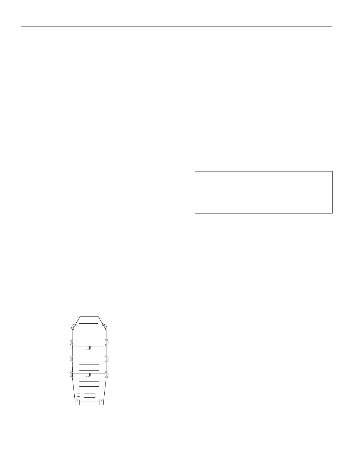
Head end
Foot end
Left
Right
Actions before first use (when delivered)
1 Visually inspect the Maxi Air Transfer and the
Maxi Air Tr ansfer Flites for damage.
2 Check that all parts are supplied. Compare with
section Parts Designation in this IFU.
If any part is missing or damaged - do NOT use
the product!
3 Read the IFU.
4 Disinfect the Maxi Air Transfer.
See section Disinfection Instructions.
5 Perform a functionality test.
See section Care and Preventive Maintenance.
6 Find a good ventilated dry area for storing the
Maxi Air Tr ansfer and the Maxi Air Transfer
Flites.
7 Choose a designated area where the IFU should
be kept, accessible at all times.
8 Make sure to have a rescue plan ready in case of a
patient emergency.
9 If you have any questions, please contact your
local ArjoHuntleigh representative for support
and service. The contact information (Arjo-
Huntleigh addresses) is listed at the end of this
IFU.
Below is the direction of the
Maxi Air Transfer Flites:
Actions before every new patient
1 Select a suitable Maxi Air Transfer Flites size
according to sections Correct placement of the
patient and Product Specifications.
2 Check that all parts of the Maxi Air Transfer and
the Maxi Air Transfer Flites are in place.
Compare with the section Parts Designation in
this IFU.
3 Carry out a thorough inspection for damage.
4 If any part is missing or damaged - do NOT use
the product!
5 Enter the patient name and date on the Maxi Air
Transfer Flites label. See section Labels on the
Maxi Air Transfer Flites.
6
WARNING
To prevent cross-contamination, always
follow the disinfection instructions in
this Instructions for Use.
Make sure the Maxi Air Transfer is disinfected
according to section Disinfection Instructions.
7 If you have any questions, please contact your
local ArjoHuntleigh representative for support
and service. The contact information (Arjo-
Huntleigh addresses) is listed at the end of this
IFU.
Actions before every transfer
(with same patient)
1 Check that all parts are in place. Compare with the
Parts Designation in this IFU.
2 Carry out a thorough inspection for damage.
3 If any part is missing or damaged - do NOT use
the product!
7
Page 8
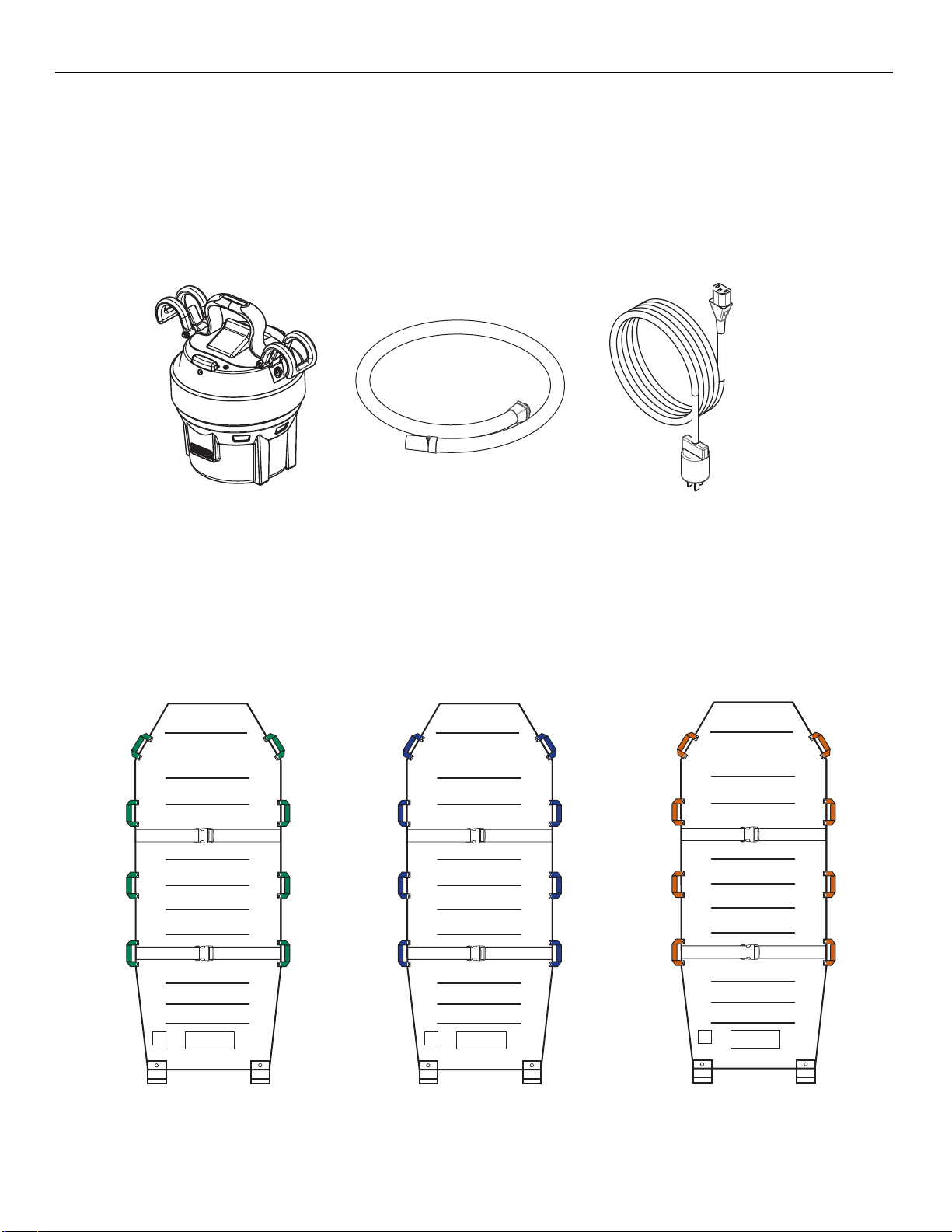
Product Specifications
L (Green handles)
XL (Blue handles)
XXL (Orange handles)
Maxi Air Transfer
Dimensions: 12,5 x 7 x 7”(317,5 x 178 x 178 mm)
Weight: 11 lbs. (5 kg)
Material: Fire Retardant ABS, NBR
Air Hose Length: 78” (1980 mm)
Pow e r C o r d L e n g t h : 180” ( 4570 mm)
Maxi Air Transfer Flites
Widths: L 34” (860 mm), XL 39” (990 mm) and XXL 50” (1270 mm)
Length: 78” (1980 mm)
Material: Non-woven top, nylon back
8
Page 9

Intentionally left blank
9
Page 10
Applied part:Type B.
protection against electric shock in accordance
with IEC 60601-1
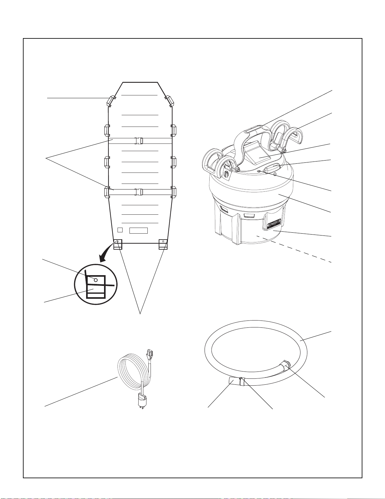
Parts Designation
Maxi Air Transfer
1 Carrying handle
2 Attachment hooks
3 Socket inlet
4 Push button (On/Off)
5 LED mains power indicator
6 Rubber bumper
7 Cover
8 Air filter (inside)
9 Air hose
10 Socket
11 Snap lock button (air hose)
12 Nozzle
13 Power cord (Mains disconnection device)
Maxi Air Transfer Flites
14 Connection points
15 Velcro lip
16 Snap lock button
17 Safety belts
18 Transfer handles
10
Page 11
18
1
2
3
17
16
15
4
5
6
7
8
14
9
13
11
12
10
11
Page 12
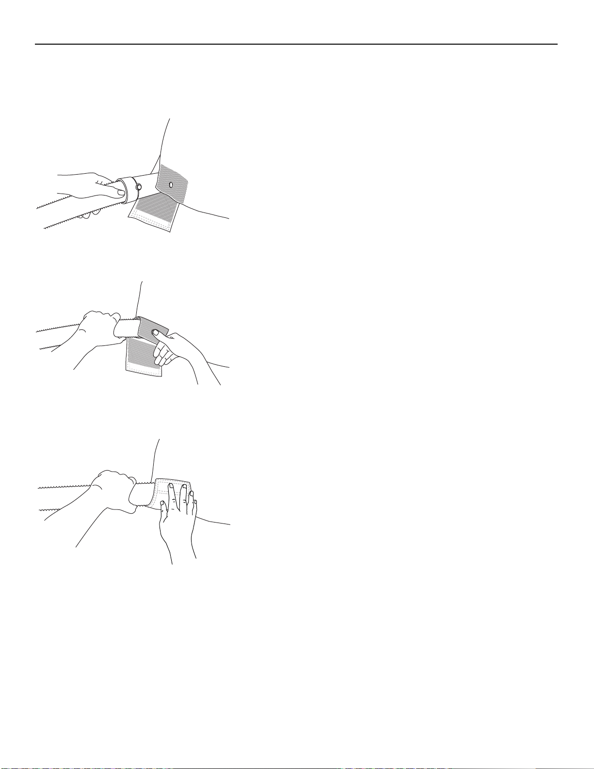
Fig. 1
Fig. 2
Fig. 3
Product Description/Functions
Maxi Air Transfer and Maxi Air Transfer Flites connection
1 Connect the air hose from the Maxi Air Transfer, to either
the left or right foot end connection point of the Maxi Air
Transfer Flites. (See Fig. 1)
2 Attach the snap lock button on the Maxi Air T ransfer Flites
to the air hose snap lock button. (See Fig. 2)
3 Use the velcro lip to secure the air hose in place. (See Fig. 3)
Operation and controls
1 Plug in the power cord from the Maxi Air Transfer to an
electrical outlet.
2 The LED will light up to indicate that the mains is turned on.
3 T o inflate the Maxi Air Transfer Flites, press the push button
on the Maxi Air Transfer.
4 To deflate the Maxi Air Transfer Flites, press the push but-
ton again.
Mains disconnection device
If for any reason, the Maxi Air Transfer does not respond to the
push button, stop inflating by pulling out the power cord from the
electrical outlet.
Do not place anything in front of the electrical outlet. Make sure
the outlet is easily accessible.
Contact qualified personnel if a malfunction occurs.
12
Page 13

Correct placement of the p atient
Fig. 1
Fig. 2
Fig. 3
WARNING
Always make sure the patient has the correct size of the Maxi Air Transfer Flites. If the Maxi
Air Transfer Flites is too narrow, the Maxi Ai r T ransfer Flites can tip over during transfer caus-
ing serious injury to the patient and the caregivers.
WARNING
To avoid bodily injury make sure the patient is correctly positioned on the Maxi Air Transfer
Flites. If the patient is incorrectly positioned, the Maxi Air Transfer Flites can tip over during
the transfer.
Placement of the patient
• Make sure the patient is placed in the middle of the Maxi Air Transfer Flites. (See Fig. 1)
• Make sure the patient’s body does NOT reach outside the boundaries of the Maxi Air Transfer Flites.
If the feet reach outside the foot end, make sure there is enough space for the transfer. (See Fig. 2)
• The patient’s head should be placed approximately 6” (150 mm) from the top of the M axi Air Transfer Flites.
Make sure the patient rests conveniently against the pillow during the transfer. (See Fig. 3)
13
Page 14

Correct placement of the Maxi Air Transfer
Fig. 1
WARNING
Before every transfer , always make sure the Maxi Air Transfer is:
• secured from movement and from falling
• not in the way of the electrical outlet in use
• not placed on the floor
Incorrectly placed Maxi Air Transfer can cause hazards e.g. interrupted inflation. This can
cause serious injury to the patient and the caregivers.
WARNING
To avoid tripping hazards, make sure that the power cord on the floor is rolled up before the
transfer.
Placement of the Maxi Air Transfer
• Hang the Maxi Air T ransfer on the receiving surface by the
attachment hooks. Make sure it is secured from movement
and from falling down. (See Fig. 1)
• Make sure the Maxi Air T ransfer is not placed in front of the
electrical outlet that is being used.
• Make sure the power cord on the floor is rolled up.
14
Page 15

Transfer
Fig. 1
Fig. 2
Transfer between surfaces (21 steps)
Sending surface/side = surface the patient lays on
Receiving surface/side = surface the patient is transferred to
1 Apply the brakes on the sending surface.
2 Make sure the patient is in a horizontal position.
3
WARNING
To avoid the patient from falling or caregiver
from being injured, ensure that there are two or
more caregivers present during the transfer.
Position one caregiver on each side of the patient.
(See Fig. 1)
4Place the Maxi Air T ransfer Flites with the labels upwards,
underneath the patient. Follow local routines.
5 Make sure the patient is correctly placed on the Maxi Air
Transfer Flites.
6
WARNING
To prevent patient from rolling off the Maxi Air
Transfer Flites, the safety belts must be used
during the entire movement.
Attach the safety belts loosely. If the belts are attached too
tight, they can cause discomfort during the inflation.
Tighten them after the inflation.
(See Fig. 2)
7 Adjust the receiving surface to an ergonomic height.
8 Place the receiving surface as close as possible to the send-
ing surface.
continue with the steps on the next page
15
Page 16

9 Adjust the sending surface height slightly higher than the
Fig. 3
Receiving
Sending
surface
surface
receiving surface. (See Fig. 3)
10
WARNING
T o avoid bodily injury during the transfer , always
make sure to:
• apply the brakes on both the sending and
receiving surface
• raise and lock the bed rail on the receiving
surface
Apply the brakes, raise and lock the outer bed rail on the
receiving surface.
NOTE
If the receiving surface does not have any bed rail,
the caregiver on the receiving side is responsible to
make sure the patient does not reach outside the
boundaries of the receiving surface.
11 Hang the Maxi Air Transfer on the receiving surface.
12 Plug the power cord into an electrical outlet.
13
WARNING
To avoid sudden deflation make sure the air
hose is properly connected before transfer.
Sudden deflation can cause bodily injuries to
both the patient and caregivers.
Receiving side: connect the air hose to the Maxi Air T rans-
fer Flites.
14 Sending side: firmly hold the transfer handles during the
inflation of the Maxi Air Transfer Flites.
Receiving side: turn on the Maxi Air Transfer and inflate
the Maxi Air Transfer Flites.
continue with the steps on the next page
16
Page 17

15
Fig. 4
Fig. 5
Fig. 6
WARNING
To avoid bodily injury, make sure the Maxi Air
Transfer Flites is completely inflated before
starting the transfer. A partly inflated Maxi Air
Transfer Flites can cause the patient to hit the
underlying surface, causing bodily injury.
The pull force will increase with a partial inflated
mattress and this can cause bodily injury to the
caregiver as well.
Sending side: feel underneath the Maxi Air T ransfer Flites
to make sure that the patient can’t be felt through it.
(See Fig. 4)
If any part of the patient can be felt, the Maxi Air Transfer
Flites is partly inflated. To correct this problem:
• abort the inflation,
• reposition the patient and
• inflate again.
16 Sending side: tighten the safety belts and push the Maxi Air
Transfer Flites firmly towards the receiving surface.
(See Fig. 5)
NOTE
Use the transfer handles that are closest to the
widest parts of the patient’s body. (See Fig. 6)
continue with the steps on the next page
17
Page 18

17 Receiving side: meet up the air mattress when it is halfway
Fig. 7
Fig. 8
Fig. 9
over the receiving surface. (See Fig. 7)
18
WARNING
To avoid bodily injury, make sure that the Maxi
Air Transfer Flites is centred on the receiving
surface, before the Maxi Air Transfer Flites is
deflated. If not centred, the patient can fall
down.
Receiving side: make sure the Maxi Air Transfer Flites is
centred. (See Fig. 8)
19 Sending side: turn off the Maxi Air T ransfer and detach the
hose from the Maxi Air Transfer Flites.
Receiving side: firmly hold the handles until the Maxi Air
Transfer Flites is completely deflated. (See Fig. 9)
20 After the transfer is completed:
• unbuckle the safety belts,
• lock all side rails (if possible),
• remove the Maxi Air Transfer Flites and
• remove and disinfect the Maxi Air Transfer, see section
Disinfection Instructions.
18
Page 19

Intentionally left blank
19
Page 20

Disinfection Instructions
WARNING
Do NOT wash the Maxi Air Transfer Flites!
The Maxi Air Transfer Flites is a p atient specific product and is not intended for use
between patients.
If the Maxi Air Transfer Flites is washed, the
paper coating will disappear, revealing a
DO NOT REUSE sign.
WARNING
T o prevent cross-cont amination, always follow the disinfection instructions in this
Instructions for Use.
CAUTION
Do not lower down the Maxi Air Transfer in
disinfectant solution. This could damage
the electrical components and cause internal corrosion.
For the best results, only use
ArjoHuntleigh branded disinfectant.
If you have any questions regarding disinfecting the
equipment or wish to order disinfection fluid (see
section Parts and Accessories), contact your local
ArjoHuntleigh representative.
Accessories for disinfecting the
Maxi Air Transfer
• Protective gloves
• Protective glasses
• Spray bottle
• Disinfectant fluid
WARNING
Always use protective gloves and protective eye wear when dealing with concentrated disinfectant. Avoid getting it on your
skin or in your eyes.
If contact occurs, rinse with large amounts
of water. If skin or eyes become irritated,
consult a physician.
WARNING
To avoid eye or skin irritation, never disinfect in the presence of a patient.
CAUTION
To avoid damage on the equipment only
use ArjoHuntleigh branded disinfectant s.
• Cleaning brush
• Wash cloth
Disposable paper towels
The following procedure should be carried
out between patients.
20
Page 21

Disinfection of the Maxi Air Transfer
Fig. 1
A
Fig. 2
(16 steps)
1 Use protective gloves and glasses. (See Fig. 1)
2 Prepare the solution for submerging the air hose.
Make sure it is mixed according to the instructions
on the disinfectant bottle label.
3 Remove the air hose from the Maxi Air Transfer
by turning the hose socket (A) counter clock-wise
and pull the air hose out. (See Fig. 2)
Air hose:
4 Rinse the outside of the air hose with warm water
for 10 sec.
5 Use a spray bottle containing disinfection fluid
mixed according to the instructions on the disinfection bottle label. Spray the outside of air hose
with disinfectant.
6 Brush the surface of the air hose with the cleaning
brush until all visible dirt is removed.
7 Roll up the air hose and lower it down into the disin-
fectant solution.
8 Leave the air hose in the solution for a minimum
of five minutes and a maximum of ten minutes.
9 Rinse the air hose with cold water until there are
no visible traces of the disinfectant.
10 Wipe the air hose dry with disposable towels.
Maxi Air Transfer:
11 Use a damp wash cloth (warm water) to wipe off all
surfaces on the Maxi Air Transfer.
12 Use a spray bottle containing disinfection fluid
mixed according to the instructions on the disinfection bottle label. Spray the Maxi Air Transfer
with the disinfectant and allow a disinfection time
according to the instructions on the disinfectant
bottle label.
13 Make sure all surfaces are disinfected and rub
them with the wash cloth.
14 Use a new damp wash cloth (cold water) to wipe off
all surfaces on the Maxi Air Transfer until there
are no visible traces of the disinfectant.
15 Wipe the Maxi Air Transfer dry with disposable
towels.
16 Insert the air hose socket to the Maxi Air T ransfer
socket inlet. Make sure it clicks into place.
21
Page 22

Care and Preventive Maintenance
The Maxi Air T ransfer and the Maxi Air Transfer Flites are subject to wear and tear, and the following actions must be
performed to make sure that the product remains within its original manufacturing specification.
WARNING
To avoid malfunction resulting in injury, make sure to conduct regular inspections and follow
the recommended maintenance schedule. In some cases due to heavy use of the product and
exposure to aggressive environment more frequent inspections should be carried out. Local
regulations and standards may be more stringent than the recommended maintenance
schedule.
WARNING
T o avoid injury to both p atient and caregiver , never modify the equipment or use incomp atible
parts.
Preventive maintenance schedule for Maxi Air Transfer and the Maxi Air Transfer Flites.
CAREGIVER OBLIGA TIONS Action/Check
Disinfect X
Visually check all exposed parts X
Perform functionality test X
Check/change the air filter X
Between
PATIENTS
Every
TRANSFER
Every
WEEK
Every
MONTH
WARNING
To avoid injury and/or unsafe product, the maintenance activities must be carried out at the
correct frequency by qualified personnel using correct tools, parts and knowledge of procedure. Qualified personnel must have documented training in maintenance of this device.
QUALIFIED PERSONNEL Action/Check
Every
YEAR
Change the air filter X
Perform functionality test X
NOTE
All Caregiver Obligations are to be checked when performing the Qualified Personnel Service.
22
Page 23

Caregiver Obligations
Caregiver obligations shall be carried out by personnel with
sufficient Maxi Air Transfer and the Maxi Air Transfer Flites
knowledge following the instructions in this IFU.
Between Patients
Disinfect the Maxi Air Transfer. Make sure the Maxi Air
Transfer is disinfected between patients according to section
Disinfection Instructions.
Every transfer
• Visually check all exposed parts for;
- damages,
- tears and
- unhygienic signs.
Check especially the Maxi Air Trans fer Flites since it has been
in contact with both the patient and the caregivers.
Every week
• Perform functionality test. Check the;
- on/off function of the Maxi Air Transfer,
- air hose connection at the Maxi Air Transfer and Maxi Air
Transfer Flites and
- air hose for damage.
Every month
Check/change the air filter. Check the air filter for dirt.
If needed, replace it. See section Check/change the air filter.
Yearly
Maxi Air Transfer has to be serviced according to the section
Care and Preventive Maintenance schedule by qualified per-
sonnel.
23
Page 24

Check/change the air filter
Fig. 1
A
Fig. 2
C
B
Fig. 3
D
Check/change the air filter (6 Steps)
1 Fold in the attachment hooks (A). (See Fig. 1)
2 Pull up the rubber ring (B). (See Fig. 2)
3 Pull down the cover (C). (See Fig. 2)
4 Check the air filter (D) for dirt. (See Fig. 3)
5 If the air filter is dirty, replace it. Do not use the Maxi Air
Transfer until the air filter has been changed.
6 Attach the cover (C) and the rubber ring (B). (See Fig. 2)
If the product does not work as intended, immediately contact
your local ArjoHuntleigh representative for support.
24
Page 25

Troubleshooting
Troubleshooting for Maxi Air Transfer and the Maxi Air Transfer Flites
PROBLEM ACTION
• Check power supply.
• Check power cord connections on the Maxi Air
No air flow.
Transfer and the electrical outlet.
• Check air hose connections between the Maxi Air
Transfer and the Maxi Air Transfer Flites.
• Check the air hose for damage.
Low pressure in the Maxi Air Transfer Flites.
NOTE
If the problem cannot be solved with the written troubleshooting actions, please contact qualified
personnel.
• Check the Maxi Air Transfer Flites for damage.
• Make sure the air filter is clean.
25
Page 26

Technical Specifications
Technical Data
Maxi Air Transfer
Weight 11 lbs. (5 kg)
Expected life 5 years from manufacturing date
Protection class Not protected against ingress of water
Pollution degree 2
Operating force: Push button 30.0 N
Maximum duty cycle For continuous use
Sound Level 74 db (A)
MRI classification MR unsafe
Motor power 120 V 1100 W (USA)
230 V 1200 W (Rest of the world)
Maxi Air Transfer Flites
Safe working load (SWL)
(Maximum patient weight)
Weight 2 lbs. (1 kg)
Expected life 20 transfers
Shelf life Estimated shelf life (2 years) starts from the
Medical equipment type
MRI classification MR Safe
Radiolucency classification Radiolucent
Latex content Latex free
1200 Ibs. (544 kg)
manufacturing date stated on LOT label on
the outer package.
WARNING
To avoid electric shock, make sure that the equipment is connected to:
• Continuously powered supply mains with protective earth.
• Separate fuse and ground fault circuit interrupter (GFCI)
• A mains disconnection device
• Equipotential bonding point
All installations must be in accordance with local codes and regulations.
26
Page 27

Allowed Combinations
Products Compatible with Model
Maxi Air Transfer ArjoHuntleigh Maxi Air Transfer Flites L, XL, XXL
Maxi Air Transfer
Flites L, XL, XXL
No other combinations are allowed.
Environmental Conditions
Operating
Temperature +10°C to + 34°C (+50 to +93°F)
Humidity 10-70% at +20°C (+68°F)
ArjoHuntleigh Maxi Air Transfer
Hovertech AIR200G
(only compatible with Maxi Air Transfer Flites size L)
Manufactured before 20120101
Hovertech AIR400G
Manufactured before 20120101
Hovertech HT AIR1200
Manufactured before 20120101
AirPal PA-1200
Manufactured before 2011
Atmospheric pressure 700 hPa to 1060 hPa
Transport and Storage
Temperature -40°C to +80°C (-40°F to +176°F) Maxi Air T ransfer
-17°C to +43°C (+0°F to +110°F) Maxi Air Transfer Flites
Humidity 10-70% at +20°C (+68°F)
Atmospheric pressure 500 hPa to 1060 hPa
27
Page 28

Recycling
The device should be recycled according to national regulations.
Package Wood and corrugated cardboard
recyclable
Maxi Air Transfer Electric, metal and plastic parts shall be separated and
recycled according to (WEEE) and according to markings on the unit.
Disposal (Environmental Protection)
Maxi Air Transfer The device is marked with the WEEE symbol to indicate
that it is electronic equipment covered by the Directive
2002/96/EC on waste electrical and electronic equipment.
In European countries the crossed out wheeled-bin
WEEE symbol reminds you that all the electrical and
electronic products, batteries and accumulators must be
taken to separate collection at end of their working life.
This requirement applies in the European Union. Do not
dispose these products as unsorted municipal waste.
You can return your device and accessories to ArjoHuntleigh.
You can also contact your local authorities for advice on
disposal.
Maxi Air Transf er Flites The hospitals should follow local routine for disposal of
contaminated material.
28
Page 29

Intentionally left blank
29
Page 30

Labels on Maxi Air Transfer Flites
TEX
REF
T ype B, Applied part: protection against electrical
shock in accordance with
IEC 60601-1.
Follow Instructions for Use
Read the Instruction for
Use before use
LOT number
MR-Safe
Foot end of mattress
Manufacturing date
The shelf life (2 years) of
the Maxi Air Transfer Flites
starts from the manufacturing date on the LOT label
on the outer package
LALAEX
Latex free product
Model number
Do not wash
Do not reuse
Appears if the Maxi Air
Transfer Flites is washed
The name and address of
the manufacturer.
30
Page 31

Maxi Air Transfer Flites
MAS014000-WW
LOT
Patient Name:
Date:
L
Data label
31
Page 32

Labels on Maxi Air Transfer
A
B
C
Fig. 1
A1
A2
D
IP2X Protection class: The
product must only be used
in a dry location.
Class I Insulation class
V ~ Hz Voltage and AC frequency
W Motor power
Separate electrical and
electronic components for
recycling in accordance
with the European Directive 2002/96/EC (WEEE)
Follow Instructions for
Use
The equipment has been EMC-tested and fulfils all
requirements according to IEC-60601-1-2.
Identification label
The identification label is found under the top lid.
It states the product number, the serial number and the
manufacturing date.
Position of Identification label
Remove the attachment hooks, handle and lid
(See Fig. 1)
1 Turn the screws (A) to an unlocked (A1) position.
2 Remove the attachment hooks and handle (B)
by pulling the handle upward and side to side at
the same time.
3 Remove the lid (C) to find the Identification
label (D).
XXXXXXXXXX Serial Number
(located inside)
Push button
MR unsafe
Classified by Underwriters
Laboratories Inc. with
respect to electrical
shocks, fire and mechanical, hazards and other
specified hazards only in
accordance with the
Approvals and List of
Standards. See Approv-
als and List of Standards
Attach the attachment hooks, handle and lid
(See Fig. 1)
1 Attach the lid (C).
2 Push down the attachment hooks (B) and handle.
Make sure they click into place.
3 Turn the screws (A) to a locked (A2) position.
4ML5 Certificate control number
for UL.
The name and address of
the manufacturer.
32
Page 33

Product no
XXX XXXX-
Serial no
XX
XXXXXXXXXX
Made by Arjo in Eslov, Sweden
YYMMDD
Identification Label
Push button
Maxi Air Transfer
Product Name
MR unsafe
Company Logo
Maxi Air Transfer, Model: MASXXXXXX-US
ArjoHuntleigh AB,Verkstadsvägen 5, 241 38 Eslöv (SWEDEN). Made in Sweden
Data label
33
Page 34

Approvals and List of Standards
CERTIFICATE STANDARDS
UL EN/IEC 60601-1: 2005, Medical electrical equipment.
General requirements for safety.
UL CAN/CSA-C22.2 No. 601.1, Medical equipment Certified for Canada
34
Page 35

Electromagnetic comp atibility
Medical electrical equipment needs special precautions regarding EMC (Electromagnetic compatibility) and needs to
be used according to the EMC information below . The Maxi Air Transfer is intended for use in the electromagnetic
environment specified below . The customer or the user of the Maxi Air Transfer should make sure that it is used in
such an environment.
WARNING
Stacking or placing other electrical equipment next to this device is not recommended, it can
interfere with the equipment’s operation and safety. Portable and mobile radio-frequency (RF)
communications equipment can interfere with this equipment operation and safety.
WARNING
The equipment may cause radio interference or may disrupt the operation of nearby equipment. It may be necessary to take action, such as reorienting, relocating the equipment or
shielding the location.
Guidance and manufacturer’s declaration - electromagnetic emissions
Emissions test Compliance Electromagnetic environment - guidance
RF emissions
CISPR 11
RF emissions
CISPR 11
Harmonic emissions
IEC 61000-3-2
Voltage fluctuations/
flicker emissions
IEC-61000-3-3
Group 1 The Maxi Air Transfer uses RF energy only for its internal func-
tion. Therefor, its RF emissions are very low and are not likely to
cause any interference in nearby electronic equipment. RF emissions.
Class B
Class B
Complies
The Maxi Air Transfer is suitable for use in all establishments
other than domestic and those directly connected to the public low
voltage power supply network that supplies buildings used for
domestic purposes.
35
Page 36

Guidance and Manufacturer’s declaration - Electromagnetic Immunity
The Maxi Air T ransfer is intended for use in the electromagnetic environment specified below. The customer or
the user of the Maxi Air Transfer should ensure that it is used in such an environment.
Guidance and manufacturer’s declaration - electromagnetic immunity
Immunity Test IEC 60601 Test Level Compliance Level Electromagnetic Environment
Guidance
Electrostatic Discharge
(ESD)
IEC 61000-4-2
Electrical fast
Transient/burst
IEC 61000-4-4
Surge
IEC 61000-4-5
Voltage dips, short
interruptions and voltage variations on power
supply input lines
IEC 61000-4-11
± 6 kV contact
± 8 kV air
± 2 kV for power supply lines
± 1 kV for input-output
± 1 kV line(s) to
line(s)
± 2 kV line(s) to PE
< 5% UT
(>95% dip in UT)
For 0,5 cycle
40% UT
(60% dip in UT)
70% UT
(30% dip in UT)
< 5% UT
(>95% dip in UT) for
five seconds
± 6 kV contact
± 8 kV air
± 2 kV for power supply
lines
± 1 kV for input-output
± 1 kV line(s) to line(s)
± 2 kV line(s) to PE
< 5% UT
(>95% dip in UT)
For 0,5 cycle
40% UT
(60% dip in UT)
70% UT
(30% dip in UT)
< 5% UT
(>95% dip in UT) for
five seconds
Floors should be wood, concrete
or ceramic tile. If floors are covered with synthetic material, the
relative humidity should be at
least 30%
Mains power quality should be
that of a typical commercial or
hospital environment.
Mains power quality should be
that of a typical commercial or
hospital environment.
Mains power quality should be
that of a typical commercial or
hospital environment.
If the user of the Maxi Air Trans-
fer requires continued operation
during mains interruptions, it is
recommended that the Maxi Air
Transfer be powered from an
interruptible power supply or battery.
Power Frequency
(50/60 Hz) magnetic
field
IEC 61000-4-8
NOTE
UT is the AC mains voltage prior to application of the test level.
3A/m 3A/m Power frequency magnetic fields
36
should be at levels characteristic
of a typical commercial or hospital environment.
Page 37

Guidance and Manufacturer’s declaration - Electromagnetic Immunity
Guidance and manufacturer’s declaration - electromagnetic immunity
Immunity Test IEC 60601 Test Level Compliance Level Electromagnetic Environment Guid-
ance
Conducted RF
IEC 61000-4-6
Radiated RF
IEC 61000-4-3
3 Vrms 150 kHz to 80
MHz
3 Vrms 80 kHz to 2,5
GHz
3V
3 Vm
Portable and mobile RF communications equipment should be used no
closer to any part of the Maxi Air
Transfer including cables, than the
recommended separation distance
calculated from the equation applicable to the frequency of the transmitter.
Recommended separation distance
d=1,2√P
d=1,2√P 80 MHz to 800 MHz
d=2,3√P 800 MHz to 2.5 GHz
Where P is the maximum output
power rating of the transmitter in
watts (W) according to the transmitter manufacturer and d is the recommended separation distance in
meters (m)
Field strengths from fixed RF transmitters, as determined by an electromagnetic site survey, a) should be
less than the compliance level in
each frequency range. b) Interference may occur in the vicinity of
equipment marked with following
symbol:
NOTE 1
At 80 MHz and 800 MHz, the higher frequency range applies.
NOTE 2
These guidelines may not apply in all situations. Electromagnetic propagation is affected by absorp-
tion and reflection from structures, objects and people.
37
Page 38

Parts and Accessories
Power cord
US 8563082
Cover
86 62963
Air hose
8662971
For disinfectant, contact
your local representative.
Air filter
6305180
Maxi Air Transfer Flites
L, XL, XXL
38
Page 39

AUSTRALIA
ArjoHuntleigh Pty Ltd
78, Forsyth street
O’Connor
AU-6163 Western Australia
Tel: +61 89337 4111
Free: +1 800 072 040
Fax: + 61 89337 9077
BELGIQUE / BELGIË
ArjoHuntleigh NV/SA
Evenbroekveld 16
B-9420 ERPE-MERE
Tél/Tel: +32 (0) 53 60 73 80
Fax: +32 (0) 53 60 73 81
E-mail: info@arjohuntleigh.be
CANADA
ArjoHuntleigh Canada Inc.
1575 South Gateway Road
Unit "C"
MISSISSAUGA, ON, L4W 5J1
Tel/Tél: +1 905 238 7880
Free: +1 800 665 4831 Institutional
Free: +1 800 868 0441 Home Care
Fax: +1 905 238 7881
E-mail: info.canada@arjohuntleigh.com
ČESKÁ REPUBLIKA
ArjoHuntleigh s.r.o.
Hlinky 118
CZ- 603 00 BRNO
Tel: +420 549 254 252
Fax: +420 541 213 550
DANMARK
ArjoHuntleigh A/S
Vassingerødvej 52
DK-3540 LYNGE
Tel: +45 49 13 84 86
Fax: +45 49 13 84 87
E-mail: info.dk@arjohuntleigh.com
DEUTSCHLAND
ArjoHuntleigh GmbH
Peter-Sander-Strasse 10
D-55252 MAINZ-KASTEL
Tel: +49 (0) 6134 186 0
Fax: +49 (0) 6134 186 160
E-mail: info-de@arjohuntleigh.com
ΕΛΛΑ∆Α
C. Psimitis Co Ltd
Dimitriou Andr. 59
GR-16121 KAISARIANI ATTIKIS
Τηλ: 21 0724 36 68
Φάξ: 21 0721 55 53
ESPAÑA
ArjoHuntleigh Ibérica S.L.
Ctra. de Rubí, 88 1ª planta - A1
08173 Sant Cugat del Vallés
ES- BARCELONA 08173
Tel: +34 93 583 11 20
Fax: +34 93 583 11 22
E-mail: info.es@arjohuntleigh.com
FAR EAST
ARJO Far East Limited
Unit 3A, 4/F., block B Hoi Luen
Industrial Centre
55 Hoi Yuen Road,
Kwun Tong, Kowloon
HONG KONG
Tel: +852 2508 9553
Fax: +852 2508 1416
FRANCE
ArjoHuntleigh SAS
2 Avenue Alcide de Gasperi
BP 133
59436 RONCQ CEDEX
Tél: +33 (0) 3 20 28 13 13
Fax: +33 (0) 3 20 28 13 14
E-mail : info.france@arjohuntleigh.com
INTERNATIONAL
ArjoHuntleigh International Ltd.
ArjoHuntleigh House
Houghton Hall Park
Houghton Regis
UK-DUNSTABLE LU5 5XF
Tel: +44 (0) 1582 745 800
Fax: +44 (0) 1582 745 866
E-mail:
international@ArjoHuntleigh.com
ITALIA
ArjoHuntleigh S.p.A.
Via di Tor Vergata 432
00133 ROMA - ITALIA
Tel: +39 (0) 6 87426211
Fax: +39 (0) 6 87426222
E-mail: Italy.promo@arjohuntleigh.com
NEDERLAND
ArjoHuntleigh Nederland BV
Biezenwei 21
4004 MB TIEL
Postbus 6116
4000 HC TIEL
Tel: +31 (0) 344 64 08 00
Fax: +31 (0) 344 64 08 85
E-mail: info.nl@arjohuntleigh.com
NORGE
ArjoHuntleigh Norway AS
Ryenstubben 2
NO-0679 OSLO
Tel: +47 22 08 00 50
Faks: +47 22 08 00 51
E-mail: post@arjo.no
POLSKA
ArjoHuntleigh Polska Sp. z o.o.
ul. Ks Piotra Wawrzyniaka 2
PL 62-052 KOMORNIKI (Poznan)
Tel: +48 61 662 15 50
Fax: +48 61 662 15 90
E-mail: arjo@arjohuntleigh.com
PORTUGAL
ArjoHuntleigh em Portugal:
MAQUET Portugal, Lda. (Distribudor Exclusivo)
Rua Poeta Bocage n.º 2 - 2G
1600-233 Lisboa, Portugal
Tel: +351 214 189 815
Fax: +351 214 177 413
E-mail: Portugal@arjohuntleigh.com
SUISSE / SCHWEIZ
ArjoHuntleigh AG
Fabrikstrasse 8
Postfach
4614 Hägendorf,
Tél/Tel: +41 (0) 61 337 97 77
Fax: +41 (0) 61 311 97 42
SUOMI
ArjoHuntleigh OY
Vanha Porvoontie 229
FI-01380 VANTAA
Puh: +358 9 4730 4320
Faksi: +358 9 4730 4999
SVERIGE
ARJO Scandinavia AB
Verkstadsvägen 5
Box 61
SE-241 21 ESLÖV
Tel: +46 (0) 413 645 00
Fax: +46 (0) 413 645 83
E-mail: kundservice@arjohuntleigh.com
UNITED KINGDOM
ArjoHuntleigh UK
ArjoHuntleigh House
Houghton Hall Park
Houghton Regis
UK-DUNSTABLE LU5 5XF
Tel: +44 (0) 1582 745 700
Fax: +44 (0) 1582 745 745
E-mail:
sales.admin@ArjoHuntleigh.com
USA
ArjoHuntleigh Inc.
2349 W Lake Street Suite 250
Addison, IL 60101
Tel: +1 630 307 2756
Free: +1 800 323 1245 Institutional
Free: +1 800 868 0441 Home Care
Fax: +1 630 307 6195
E-mail: us.info@ArjoHuntleigh.com
ÖSTERREICH
ArjoHuntleigh GmbH
Dörrstrasse 85
AT-6020 INNSBRUCK
Tel: +43 (0) 512 204 160 0
Fax: +43 (0) 512 204 160 75
www.arjohuntleigh.com
Page 40

GETINGE GROUP is a leading global provider of products and systems that
contribute to quality enhancement and cost efficiency within healthcare and life
sciences. We operate under the three brands of ArjoHuntleigh, GETINGE and
MAQUET. ArjoHuntleigh focuses on patient mobility and wound management
solutions. GETINGE provides solutions for infection control within healthcare and
contamination prevention within life sciences. MAQUET specializes in solutions,
therapies and products for surgical interventions and intensive care.
www.ArjoHuntleigh.com
ArjoHuntleigh AB
Verkstadsvägen 5
241 38 Eslöv
SWEDEN
 Loading...