

Page 1
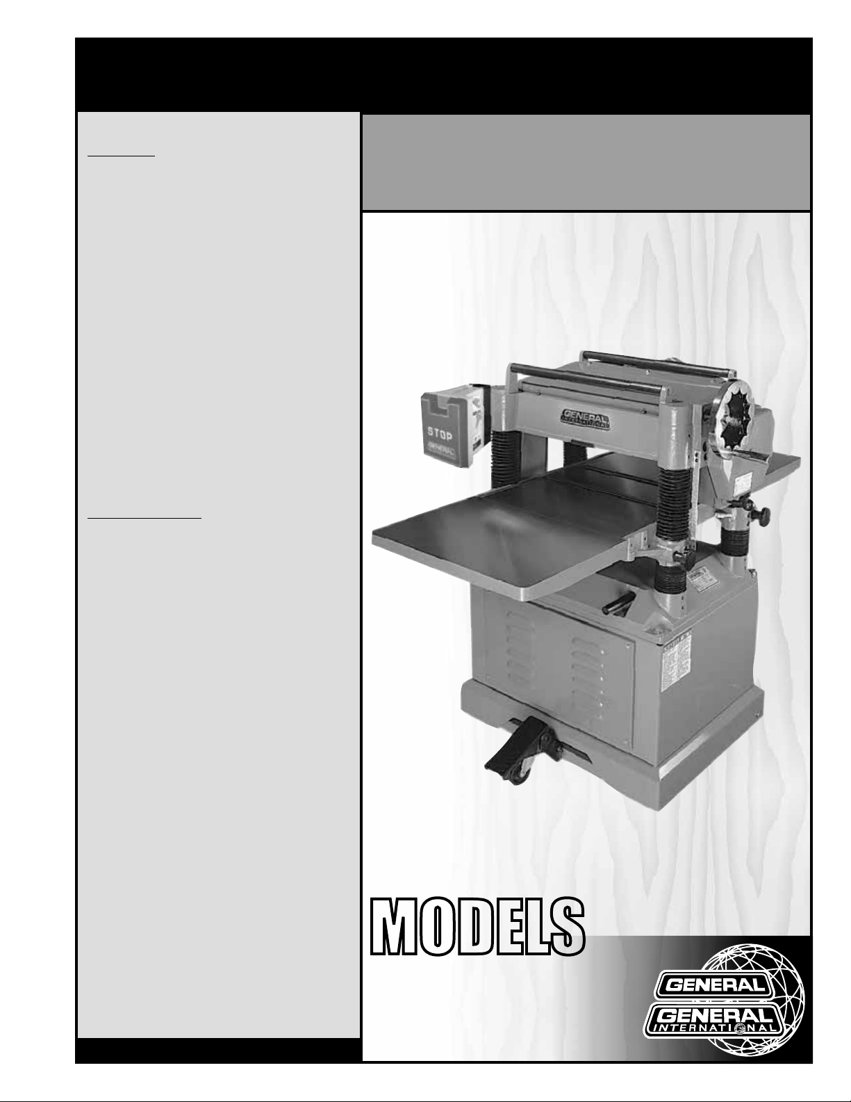
SETUP & OPERATION MANUAL
FEATURES
Large cast-iron extension wings.
Built-in mobile base with one-step lock-pedal.
Heavy-duty enclosed stand protects motor from
dust and wood chips.
Positive gear design for quick and accurate
table adjustments.
Heavy-duty cast-iron base, table, and head to
eliminate vibration.
Built-in table rollers reduce friction.
Large handwheel quickly adjusts table height.
Magnetic safety switch for added safety.
5” offset dust chute for efficient dust collection.
Convenient top mounted return rollers allow
smooth stock handling for consecutive planing/
multiple passes.
Comes with knife setting gauge (30-300 only).
Equipped with three drive belts.
20” SINGLE SURFACE PLANER
SPECIFICATIONS
• Table size
25 9/16” x 20” (650 x 508 mm)
• Extension wing sizes
(2) 15” x 21 1/4” (380 x 538 mm)
• Total surface of work table
55” x 20” (1437 x 506 mm)
• Maximum planing width
20” (508 mm)
• Maximum thickness of stock
8” (202 mm)
• Minimum thickness of stock
1/8” (3 mm)
• Minimum length of stock
6 3/4” (172 mm)
• Maximum depth of cut
1/8” (3 mm)
• Cutter head diameter
3 1/8” (80 mm)
• Cutter head speed
5000 rpm
• Feed rates
(2) 16 & 20 fpm (4.87 & 6.1 mpm)
• Cuts per inch (not applicable for HC model)
78.13 at 16 fpm & 62.5 at 20 fpm
• Number of knives / Inserts
3 - 30-300 / 58 - 30-300HC
• Dust Outlet
5" (127 mm)
• Motor
5 HP, 220 V, 1 Ph, 23.2 A
• Weight
893 lbs (406 kg) - 30-300HC
860 lbs (390 kg) - 30-300
Version #2 / Revision #1 - November 2015
© Copyright General International
*With helical cutter head
MODELS
#
30-300M1
#
30-300HC M1*
Page 2

GENERAL® INTERNATIONAL
8360 Champ-d’Eau, Montreal (Quebec) Canada H1P 1Y3
Telephone (514) 326-1161 • Fax (514) 326-5555 • www.general.ca
THANK YOU
for choosing this General® International model 30-300 or
30-300HC 20” single surface planer. This planer has been carefully tested and inspected before shipment and if properly used and maintained, will provide you with years of reliable
service. For your safety, as well as to ensure optimum performance and trouble-free operation,
and to get the most from your investment, please take the time to read this manual before
assembling, installing and operating the unit.
The manual’s purpose is to familiarize you with the safe operation, basic function, and
features of this planer as well as the set-up, maintenance and identification of its parts and
components. This manual is not intended as a substitute for formal woodworking instruction,
nor to offer the user instruction in the craft of woodworking. If you are not sure about the safety
of performing a certain operation or procedure, do not proceed until you can confirm, from
knowledgeable and qualified sources, that it is safe to do so.
Once you’ve read through these instructions, keep this manual handy for future reference.
DISCLAIMER: The information and specifications
in this manual pertain to the unit as it was supplied
from the factory at the time of printing. Because we
are committed to making constant improvements,
General® International reserves the right to make
changes to components, parts or features of this unit
as deemed necessary, without prior notice and without
obligation to install any such changes on previously
delivered units. Reasonable care is taken at the factory
to ensure that the specifications and information in this
manual corresponds with that of the unit with which it
was supplied. However, special orders and “after factory”
modifications may render some or all information in
this manual inapplicable to your machine. Further, as
several generations of this model of planer and several
versions of this manual may be in circulation, if you own
an earlier or later version of this unit, this manual may
not depict your unit exactly. If you have any doubts or
questions contact your retailer or our support line with
the model and serial number of your unit for clarification.
Page 3

GENERAL® INTERNATIONAL WARRANTY
All component parts of General® International and Excalibur by General® International products
are carefully inspected during all stages of production and each unit is thoroughly inspected upon
completion of assembly.
Limited Lifetime Warranty
Because of our commitment to quality and customer satisfaction, General® International agrees to
repair or replace any part or component which upon examination, proves to be defective in either
workmanship or material to the original purchaser for the life of the tool. However, the Limited Lifetime
Warranty does not cover any product used for professional or commercial production purposes nor
for industrial or educational applications. Such cases are covered by our Standard 2-year Limited
Warranty only. The Limited Lifetime Warranty is also subject to the “Conditions and Exceptions” as listed
below.
Standard 2-Year Limited Warranty
All products not covered by our lifetime warranty including products used in commercial, industrial
and educational applications are warranted for a period of 2 years (24 months) from the date of
purchase. General® International agrees to repair or replace any part or component which upon
examination, proves to be defective in either workmanship or material to the original purchaser during
this 2-year warranty period, subject to the “conditions and exceptions” as listed below.
To file a Claim
To file a claim under our Standard 2-year Limited Warranty or under our Limited Lifetime Warranty,
all defective parts, components or machinery must be returned freight or postage prepaid to
General® International, or to a nearby distributor, repair center or other location designated by
General® International. For further details call our service department at 1-888-949-1161 or your local
distributor for assistance when filing your claim.
Along with the return of the product being claimed for warranty, a copy of the original proof of purchase
and a “letter of claim” must be included (a warranty claim form can also be used and can be obtained,
upon request, from General® International or an authorized distributor) clearly stating the model and
serial number of the unit (if applicable) and including an explanation of the complaint or presumed
defect in material or workmanship.
CONDITIONS AND EXCEPTIONS:
This coverage is extended to the original purchaser only. Prior warranty registration is not required but
documented proof of purchase i.e. a copy of original sales invoice or receipt showing the date and
location of the purchase as well as the purchase price paid, must be provided at the time of claim.
Warranty does not include failures, breakage or defects deemed after inspection by
General® International to have been directly or indirectly caused by or resulting from; improper use,
or lack of or improper maintenance, misuse or abuse, negligence, accidents, damage in handling or
transport, or normal wear and tear of any generally considered consumable parts or components.
Repairs made without the written consent of General® International will void all warranty.
Page 4

TABLE OF CONTENTS
Rules for safe operation ..................................................................................................... 5
Electrical requirements ...................................................................................................... 6
Identification of main parts and components .................................................................. 7
Unpacking .......................................................................................................................... 8
Clean-up............................................................................................................................. 8
Placement within the shop ................................................................................................ 9
Assembly instructions ................................................................................................... 9-11
Assembling the knife setting jig (for 30-300 only) ........................................................................................... 9
Installing the depth cut handwheel ............................................................................................................... 10
Intalling extension tables ................................................................................................................................. 10
Installing the dust chute ................................................................................................................................... 10
Connecting to a dust collector ....................................................................................................................... 11
Basic adjustments and controls ................................................................................. 11-12
Connecting to a power source .......................................................................................................................11
On/Off magnetic power switch ......................................................................................................................11
Overload protection ......................................................................................................................................... 11
Deph of cut adjustment ................................................................................................................................... 12
Feed speed control ..........................................................................................................................................12
Operating Instructions ................................................................................................ 11-14
Basic principles of planing .............................................................................................................................. 11
Selecting boards suitable for planing ............................................................................................................ 12
Check list before starting ................................................................................................................................. 12
Maintenance ............................................................................................................... 14-26
Adjusting the cutter head parallel to table ................................................................................................... 14
Adjusting the infeed and outfeed rollers ....................................................................................................... 15
Adjusting the chipbreaker ............................................................................................................................... 15
Adjusting the table rollers ................................................................................................................................ 17
Adjusting the feed roller spring tension ......................................................................................................... 17
Inspecting cutter head knives ......................................................................................................................... 18
Checking/setting the knives (30-300 only) .................................................................................................... 18
Knife setting or replacement (30-300 only) ................................................................................................... 20
Helical cutter head insert reversal/replacement (model 30-300HC) ........................................................ 21
Periodic maintenance ..................................................................................................................................... 22
Replacing the gear box oil ............................................................................................................................. 23
Cleaning the anti-kickback fingers ................................................................................................................ 24
Lubrication ......................................................................................................................................................... 24
Aligning the pulleys .......................................................................................................................................... 25
Adjusting belt tension ....................................................................................................................................... 25
Recommended optional accessories ............................................................................. 26
Parts list & diagrams ................................................................................................... 27-32
Contact information ........................................................................................................ 34
Page 5

RULES FOR SAFE OPERATION
To help ensure safe operation, please take a moment to learn the machine’s applications and limitations,
as well as potential hazards. General
harmless for any injury that may result from the improper use of its equipment.
1. Do not operate this planer when tired, distracted, or
under the effects of drugs, alcohol or any medica tion that impairs reflexes or alertness.
2. The work area should be well lit, clean and free
of debris.
3. Keep children and visitors at a safe distance when
the planer is in operation; do not permit them to
operate the planer.
4. Childproof and tamper proof your shop and all
machinery with locks, master electrical switches
and switch keys, to prevent unauthorized or unsu pervised use.
5. STAY ALERT! Give your work your undivided attention.
Even a momentary distraction can lead to serious
injury.
6. Fine particulate dust is a carcinogen that can be
hazardous to health. Work in a well-ventilated area
and whenever possible use a dust collector. Wear
face, eye, ear, respiratory and body protection
devices.
®
International disclaims any real or implied warranty and holds itself
13. Do not push or force stock into the cutter head. The
planer will perform better and safer when working at
the rate for which it was designed.
14. Kickback is when the workpiece is ejected at high
speeds by the force of the cutter head. To minimize
the risk of injury from kickback, use proper feeding
technique and stand to one side, out of the path of
a potential kickback.
15. Select appropriate feed speed for the stock being
planed: high speed for softwood and slow for hard woods.
16. Place stock firmly against the table and use suitable
in-feed and out-feed support if stock is too long.
17. Keep guards in place and in working order. If a
guard must be removed for maintenance or clean ing make sure it is properly attached before using
the machine again.
18. Use of parts and accessories NOT recommended
by General
malfunction or risk of injury.
®
International may result in equipment
7. Do not wear loose clothing, gloves, bracelets, neck laces or other jewelry while the planer is in ope ration. Wear protective hair covering to contain long
hair and wear non-slip footwear.
8. Be sure that adjusting wrenches, tools, drinks and
other clutter are removed from the machine and/or
the table surface before operating.
9. Keep hands well away from knives and all moving
parts. Use a push stick to feed stock, and a brush,
not hands, to clear away chips and dust.
10. Be sure that the knives are securely installed in the
cutter head.
11. Always use clean, properly sharpened knives. Dirty
or dull knives are unsafe and can lead to accidents.
12. Inspect stock and remove all foreign objects be fore planing. Make sure that any stock you plane
is clean and free of any dirt, nails, staples, tiny rocks
or any other foreign objects that may damage the
planer knives. Only process natural solid wood
boards. Never plane MDF, particle board, plywood,
laminates or other synthetic materials.
19. Never stand or lean on machinery. Serious injury
could result if the tool is tipped over or if the cutting
tool is unintentionally contacted.
20. Always disconnect the tool from the power source
before servicing or changing accessories such as
knives, or before performing any maintenance or
cleaning, or if the machine will be left unattended.
21. Make sure that the switch is in the “OFF” position be fore plugging in the power cord.
22. Make sure the tool is properly grounded. If equipped
with a 3-prong plug it should be used with a three pole receptacle. Never remove the third prong.
23. Do not use this planer for any purpose other
than its intended use. If used for other purposes,
General® International disclaims any real or implied warrantyand holds itself harmless for any injury, which may result from that use.
5
Page 6

ELECTRICAL REQUIREMENTS
BEFORE CONNECTING THE MACHINE TO THE POWER SOURCE, VERIFY THAT THE VOLTAGE OF YOUR POWER
SUPPLY CORRESPONDS WITH THE VOLTAGE SPECIFIED ON THE MOTOR I.D. NAMEPLATE. A POWER SOURCE
WITH GREATER VOLTAGE THAN NEEDED CAN RESULT IN SERIOUS INJURY TO THE USER AS WELL AS DAMAGE
TO THE MACHINE. IF IN DOUBT, CONTACT A QUALIFIED ELECTRICIAN BEFORE CONNECTING TO THE POWER
SOURCE.
THIS TOOL IS FOR INDOOR USE ONLY. DO NOT EXPOSE TO RAIN OR USE IN WET OR DAMP LOCATIONS.
ELECTRICAL CONNECTIONS
Both a manual circuit breaker (or similar device) as well
as an electrical plug (similar to the one shown) are recommended and SHOULD BE INSTALLED BY A QUALI-
FIED ELECTRICIAN.
Use locally approved wire A that includes a separate
grounding wire and a 3 prong grounding type plug B
with a matching receptacle C.
GROUNDING INSTRUCTIONS
In the event of an electrical malfunction or short circuit,
grounding reduces the risk of electric shock to the operator. The motor of this machine is wired for 220 V single
phase operation.
As with many stationary industrial type machines, because each installation situation is unique, this machine is
supplied without a power cord or plug.
The installation of an appropriate power cord and plug must be performed by a qualified electrician. The machine must be connected to an electrical source using a power cord that has a grounding wire, which must also
be properly connected to the grounding prong on the plug. The outlet must be properly installed and grounded
and all electrical connections must be made in accordance with all local codes and regulations.
A
C
B
CIRCUIT CAPACITY
Make sure that the wires in your circuit are capable of handling the amperage draw from your machine, as well as
any other machines that could be operating on the same circuit. If you are unsure, consult a qualified electrician.
If the circuit breaker trips or the fuse blows regularly, your machine may be operating on a circuit that is close to its
amperage draw capacity. However, if an unusual amperage draw does not exist and a power failure still occurs,
contact a qualified technician or our service department.
EXTENSION CORDS
The use of an extension cord is not generally recommended for 220 V equipment. If you find it necessary, use only 3-wire
extension cords that have 3-prong grounding plug and a matching 3-pole receptacle that accepts the tool’s plug.
Repair or replace a damaged extension cord or plug immediately.
Make sure the cord rating is suitable for the amperage listed on the motor I.D. plate. An undersized cord will cause a
drop in line voltage resulting in loss of power and overheating. The accompanying chart shows the correct size extension cord to be used based on cord length and motor I.D. plate amp rating. If in doubt, use the next heavier gauge.
TABLE - MINIMUM GAUGE FOR CORD
EXTENSION CORD LENGTH
AMPERES 50 feet 100 feet 200 feet 300 feet
< 5
6 to 10
10 to 12
12 to 16
*NR = Not Recommended
18 16 16 14
18 16 14 12
16 16 14 12
14 12 *NR *NR
6
Page 7
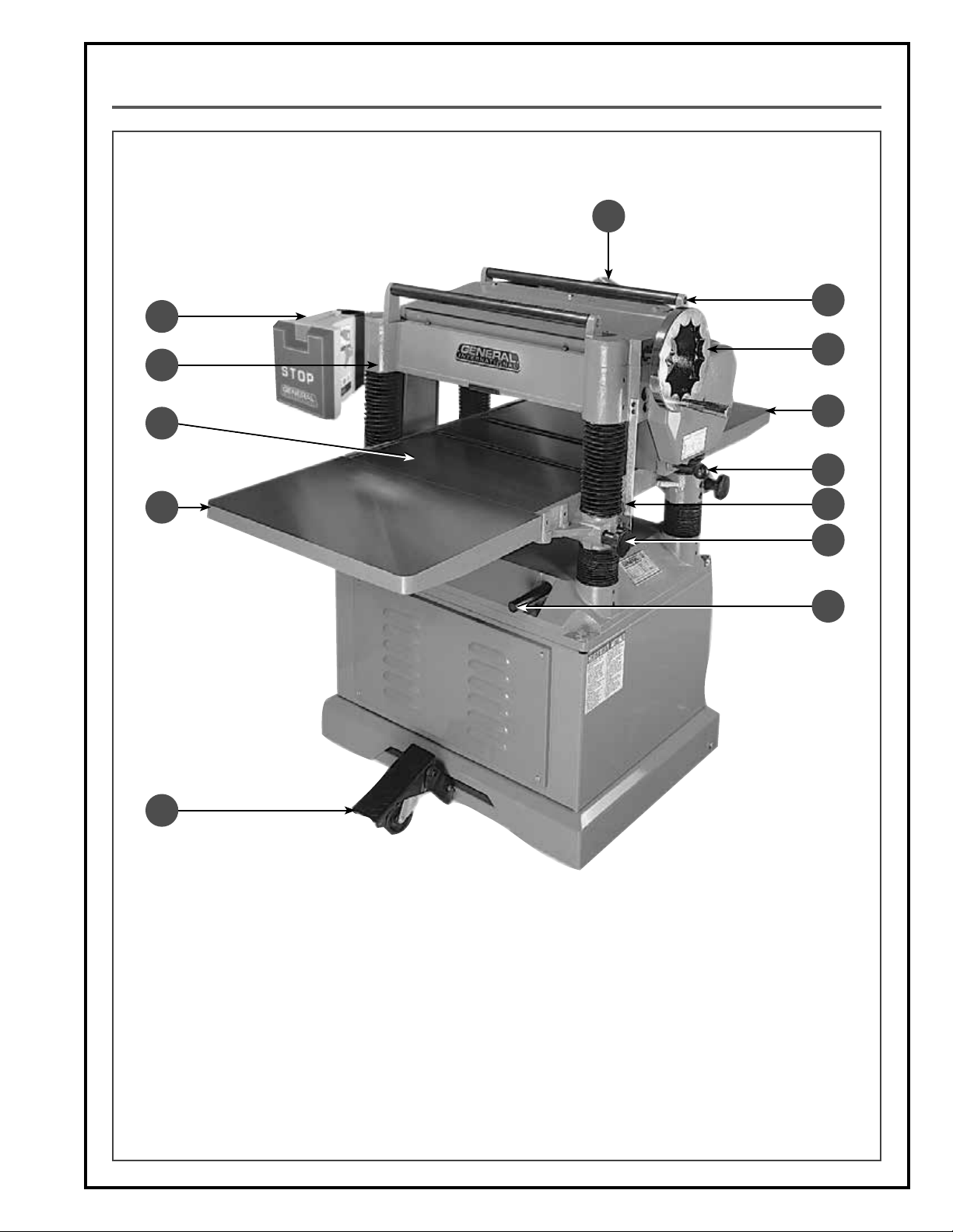
IDENTIFICATION OF MAIN PARTS AND COMPONENTS
F
D
C
B
E
G
H
I
J
K
L
M
A
A. BUILT-IN MOBILE BASE WITH LOCK-PEDAL
B. FRONT EXTENSION WING
C. MAIN TABLE
D. HEAD ASSEMBLY
E. MAGNETIC SAFETY SWITCH
F. DUST OUTLET
G. RETURN ROLLERS
H. DEPTH OF CUT ADJUSTMENT HANDWHEEL
I. REAR EXTENSION WING
J. FEED SPEED ADJUSTMENT KNOB
K. STOCK THICKNESS SCALE
L. CUTTER HEAD LOCK KNOB
M. RETRACTABLE LIFTING BAR
7
Page 8
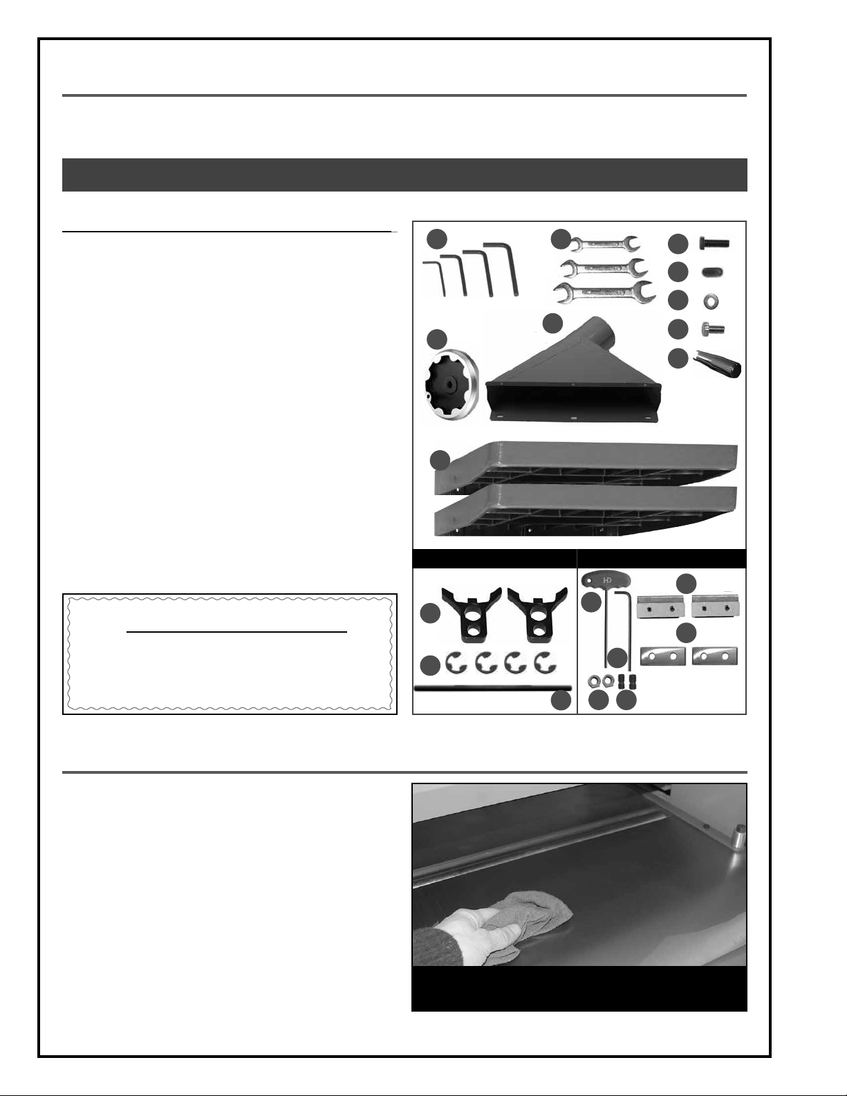
UNPACKING
Carefully unpack and remove the unit and its components from its shipping container and check for missing or
damaged items as per the list of contents below.
NOTE: PLEASE REPORT ANY DAMAGED OR MISSING ITEMS TO YOUR GENERAL® INTERNATIONAL DISTRIBUTOR IMMEDIATELY.
LIST OF CONTENTS QTY
PLANER (NOT SHOWN)..................................................................... 1
A. ALLEN KEY (3, 4, 5 & 6 MM) .................................................... 1
B. COMBINATION WRENCH (8-10
MM
, 12-14 MM & 17-19 MM) .
C. BOLT ......................................................................................... 6
D. SET SCREW ............................................................................... 6
E. WASHER (DUST CHUTE) ............................................................ 6
F. BOLT (DUST CHUTE) ................................................................. 6
G. HANDLE .................................................................................... 1
H. HANDWHEEL ............................................................................ 1
I. DUST CHUTE ............................................................................. 1
J. EXTENSION TABLE .................................................................... 2
KNIFE SETTING JIG (30-300 M1)
K. “C” CLIP.................................................................................... 2
L. KNIFE SETTING JIG FOOT PAD ................................................. 4
M. KNIFE SETTING JIG BAR ........................................................... 1
TOOLS/REPLACEMENT PARTS (
30-300HC M1
)
N. 5 MM “T” ALLEN KEY ................................................................ 1
O. 5 MM ALLEN KEY ..................................................................... 1
P. NUT ........................................................................................... 2
Q. SCREW...................................................................................... 2
R. KNIFE-HOLDER / CHIPBREAKER .............................................. 2
S. CARBIDE INSERT ....................................................................... 2
ADDITIONAL REQUIREMENTS FOR SET UP
A. PHILLIPS SCREWDRIVER
B. STRAIGHT EDGE
C. 0.004”, 0.008”, 0.020” FEELER GAUGE
D. GAUGE BLOCK
A
1
H
J
FOR 30-300 M1* FOR 30-300HC M1
L
K
*Not included and not needed for 30-300HC
B
I
N
O
P
M
Q
C
D
E
F
G
R
S
CLEAN UP
The protective coating on the planer tables prevents
rust from forming during shipping and storage. Remove
it by rubbing with a rag dipped in kerosene, mineral
spirits or paint thinner. (Dispose of potentially flammable
solvent soaked rags according to manufacturer’s safety
recommendations.)
A putty knife, held flat to avoid scratching the surface,
may also be used to scrape off the coating followed
by clean-up with solvent. Avoid rubbing the planer’s
painted surfaces, as many solvent-based products will
remove paint.
To prevent rust, apply a light coating of paste wax or
use regular applications of any after-market surface
protectant or rust inhibitor.
8
TIP: WITH A SCREW DRIVER, PUSH A SOLVENT-SATURATED
RAG INTO THE T-SLOTS TO REMOVE THE GREASE.
Page 9

PLACEMENT WITHIN THE SHOP / SAFETY ZONE
THIS MODEL 30-300 PLANER IS HEAVY. DO NOT OVER-EXERT. A HOIST OR FORKLIFT WITH STRAPS SHOULD BE USED TO
LIFT THIS MACHINE. TO LIMIT THE RISK OF SERIOUS INJURY OR DAMAGE TO THE MACHINE, ANY EQUIPMENT USED TO
LIFT THIS MACHINE SHOULD HAVE A RATED CAPACITY IN EXCESS OF 860 LBS (390 KG).
PLACEMENT WITHIN THE SHOP
This machine should be installed and operated only on
a solid, flat and stable floor that is able to support the
weight of the planer (860 lbs - 390 kg) and the operator.
Using the dimensions shown as a guideline, plan for
placement within your shop that will allow the operator
to work unencumbered and unobstructed by foot traffic (either passing shop visitors or other shop workers)
or other tools or machinery.
ESTABLISHING A SAFETY ZONE
For shops with frequent visitors or multiple operators,
it is advisable to establish a safety zone around shop
machinery. A clearly defined “no-go” zone on the floor
around each machine can help avoid accidents that
could cause injury to either the operator or the shop
visitor.
It is advisable to take a few moments to either paint
(using non-slip paint) or using tape, define on the floor
the limits or perimeter of each machines safety zone.
Take steps to ensure that all operators and shop visitors are aware that these areas are off limits whenever
a machine is running for everyone but the individual
operating the unit.
Note: To move the machine, step on the foot pedal A and
roll the machine to the desired location. Once the machine
is in place, raise the pedal to retract the built-in wheels.
17"
27 1/2"
29 1/2"
A
56"
23 1/2"
ASSEMBLY INSTRUCTIONS
BEFORE ASSEMBLING MAKE SURE THAT THE SWITCH IS IN THE “OFF” POSITION AND THAT THE POWER CORD IS
UNPLUGGED. DO NOT PLUG IN OR TURN ON THE MACHINE UNTIL YOU HAVE COMPLETED THE ASSEMBLY AND INSTALLATION STEPS DESCRIBED IN THIS SECTION OF THE MANUAL.
ASSEMBLING THE KNIFE SETTING JIG*
1. Using a pair of pliers, push a “C” clip into the inner
grooves on each end of the knife setting jig rod as
shown B.
2. Slide one foot onto one end of the rod as shown C.
3. Secure the foot on the rod by pushing a “C” clip
into the outer groove in the rod as shown D.
4. Repeat step 2 and 3 to install the other foot as
shown E. Set the jig aside for use whenever knife
settings need to be verified or adjusted.
*Not included and not needed for 30-300HC
B
D E
C
9
Page 10

BEFORE ASSEMBLING, MAKE SURE THAT THE SWITCH IS IN THE “OFF” POSITION AND THAT THE POWER CORD IS
UNPLUGGED. DO NOT PLUG IN OR TURN ON THE MACHINE UNTIL YOU HAVE COMPLETED THE ASSEMBLY AND INSTALLATION STEPS DESCRIBED IN THIS SECTION OF THE MANUAL.
INSTALLING THE DEPTH OF CUT ADJUSTMENT HANDWHEEL
1. Remove the protective tape from the handwheel
shaft.
3. Install the handwheel onto the shaft by aligning its
mounting hole with the key installed in the shaft and
secure the handwheel by retightening the nut with
the washer using a 19 mm wrench.
INSTALLING THE EXTENSION TABLES
2. Remove the nut and the flat washer from the shaft.
4. Screw the handle into the handwheel, then secure
it using a 14 mm wrench.
A
B
1. Install leveling screws B into the extension tables with
the a 3 mm Allen key so that they are flush with the
surface that faces the machine.
2. Attach the table extensions to the machine using
three hex head bolts A using the 12 mm wrench.
Note: This step requires help from an assistant.
10
3. Use a straight edge approximately four feet long to
verify table level.
Using the bolts A and set screws B, adjust so that there
4.
is no space between the straight edge and the tables.
5. Tighten bolts A and repeat the same procedure for
the other table extension.
Page 11
BEFORE ASSEMBLING, MAKE SURE THAT THE SWITCH IS IN THE “OFF” POSITION AND THAT THE POWER CORD IS
UNPLUGGED. DO NOT PLUG IN OR TURN ON THE MACHINE UNTIL YOU HAVE COMPLETED THE ASSEMBLY AND INSTALLATION STEPS DESCRIBED IN THIS SECTION OF THE MANUAL.
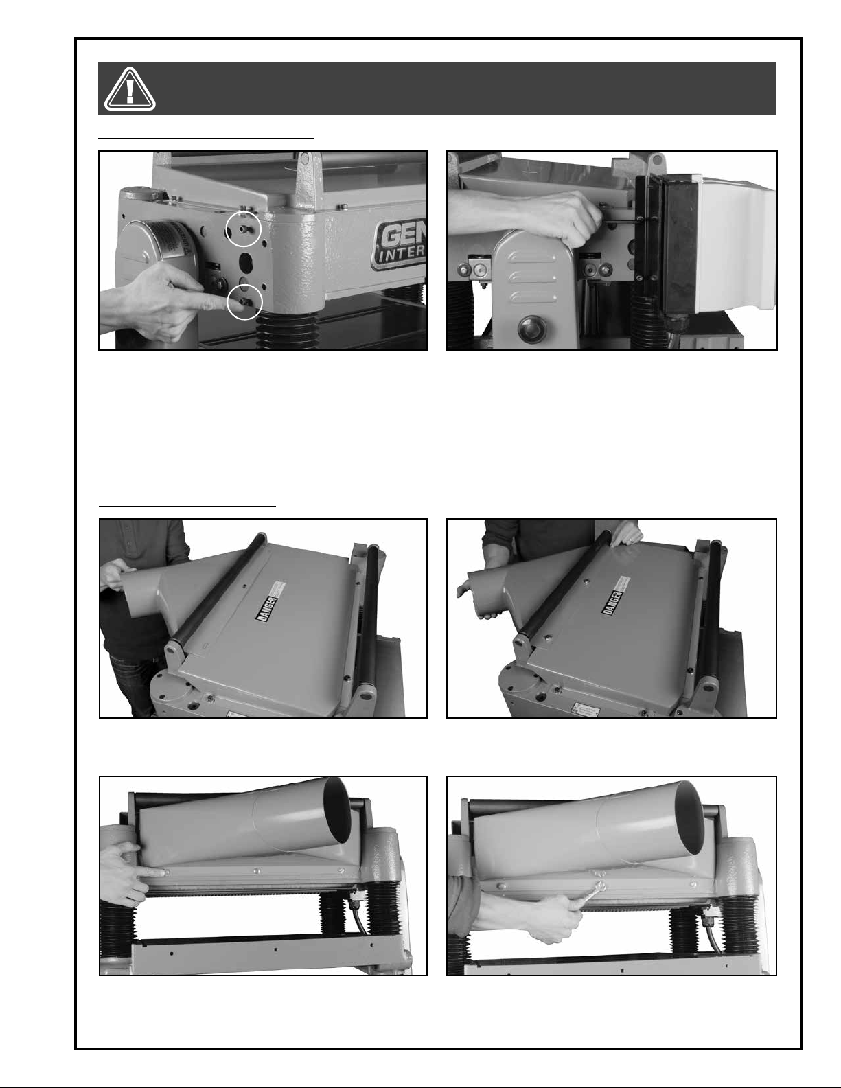
INSTALLING THE SWITCH ASSEMBLY
1. Remove the two cap screws installed on the left
front side of the machine.
INSTALLING THE DUST CHUTE
1. Align the 3 dust chute mounting holes with the cor-
responding holes in the machine.
2. Align the switch assembly mounting holes with
holes in the machine. Secure it in place using the
the two cap screws with a 5 mm Allen key.
2. Screw 3 bolts with washers into the upper part of the
dust chute by hand.
3. Screw 3 bolts with washers into the lower part of the
dust chute by hand.
4. Secure the dust chute to the machine by tightening
all 6 bolts with a 10 mm wrench.
11
Page 12

STOP
CONNECTING TO A DUST COLLECTOR
A dust port with a 5” opening is provided to accommodate connection to a dust collector (not included).
Be sure to use appropriate sized hose and fittings (not
included). Check that all connections are sealed tightly
to help minimize airborne dust. If you do not already
own a dust collection system consider contacting your
General® International distributor for information on
our complete line of dust collection systems and acces
sories or visit our Web Site at www.general.ca.
-
BASIC ADJUSTMENTS & CONTROLS
TO REDUCE THE RISK OF SHOCK OR FIRE DO NOT OPERATE THE UNIT WITH A DAMAGED POWER CORD OR PLUG.
REPLACE DAMAGED CORD OR PLUG IMMEDIATELY. TO AVOID UNINTENTIONAL START-UP, MAKE SURE THAT BOTH OF
THE POWER SWITCHES ARE IN THE OFF POSITION BEFORE CONNECTING TO A POWER SOURCE.
CONNECTING TO A POWER SOURCE
Once the assembly steps have been completed, plug
the power cord into an appropriate outlet.
Refer back to the section entitled “Electrical Require
ments” and make sure all requirements and grounding
instructions are followed.
When operations have been completed unplug the
machine from the power source.
-
SWITCH OFF
TO AVOID UNEXPECTED OR UNINTENTIONAL START-UP, MAKE SURE
THAT THE POWER SWITCH IS IN
THE OFF POSITION BEFORE CONNECTING TO A POWER SOURCE.
ON/OFF MAGNETIC POWER SWITCH
This planer is equipped with a magnetic 2-step safety
switch to prevent unintentional start-up and unauthorized
use. The switch assembly is equipped with a “START” but
ton A, an extra-large easy access stop panel B, and a
lock-out key C.
To start the planer: Insert the lock-out key C and press on
the “START” button A.
To stop the planer: Press on the “STOP” panel, B. Once the
“STOP” panel has been pressed, the planer can only be
re-started by pressing again on the “STOP” panel to re
lease the green button, then by pressing on the button A.
OVERLOAD PROTECTION
The safety switch is equipped with an overload protection feature to prevent an electrical overload from
damaging the motor. In the event of a spike in line voltage or amperage draw, the overload protector will
automatically cut off power to the motor.
To reset the overload protection switch
1. Set the power switch to the OFF position, and disconnect the machine from the power source.
2. Unscrew the 2 screws on the control box front cover. Remove the cover and press the reset button D.
Re-install the control box cover and reconnect the
machine to the power source.
12
-
A
C
B
-
D
Page 13

DEPTH OF CUT ADJUSTMENT
The depth of cut is controlled by raising and lowering the main table. The table raises and lowers on four precisionground steel columns. Removing less material per pass and taking multiple passes is always preferred to more aggressive planing. Advantages include longer blade life, better finish quality (resulting in less time sanding later) and less
likelihood of removing too much material causing the workpiece to be too thin for its intended use.
Note: Depth of cut will vary depending on the width of the workpiece, density/type of wood and moisture content of the stock.
To adjust the depth cut:
B
A
1. Loosen the two lock knobs to unlock the main table. 2. Turn the handwheel to adjust the depth of cut using
the graduated scale A. Retighten the lock knobs to
lock the main table in position.
Note: The maximum depth of cut on full width planing is 1/8”. A limiter B is provided to limit the depth of cut. If the workpiece to be cut is less than 6”, the allowable maximum depth of cut is no more than 1/4” in one pass.
FEED ROLLER SPEED CONTROL
The machine is equipped with a serrated infeed roller
and solid steel outfeed roller. When the feed rollers
are engaged, they turn and feed the stock. The feed
rollers slow automatically when the machine is under
heavy load. The feed rollers are driven by a chain and
sprocket drive, which takes power directly from the cutter head through the oil bath gearbox.
To engage the feed rollers: Pull out the lever.
To disengage the feed rollers: Push the lever back in to-
ward machine.
To change the feed speed: For 20 fpm, push the lever
in, or for 16 fpm pull the lever out. Set the lever between
the two positions to set the machine in neutral position
for zero speed.
OPERATING INSTRUCTIONS
ALWAYS PLANE IN THE GENERAL DIRECTION OF THE GRAIN. PLANING AGAINST THE GRAIN OR PLANING END GRAIN IS
DANGEROUS AND MAY CAUSE THE WORKPIECE TO SHATTER.
BASIC PRINCIPLES OF PLANING
This planer is designed to remove material from the top
face of a board in order to bring the board (or a series
of boards) down to a specific thickness.
To obtain uniform results across the length of a board,
the stock being planed must have one face that has
already been machined perfectly flat (usually on a
jointer) and the stock should be fed with this flat face
against the table.
20 fpm016 fpm
NOTE: TO AVOID DAMAGE TO THE GEARBOX, SPEED CHANGES SHOULD ONLY BE MADE WHILE THE MACHINE IS RUNNING.
FLAT FACE AGAINST
THE TABLE
13
Page 14

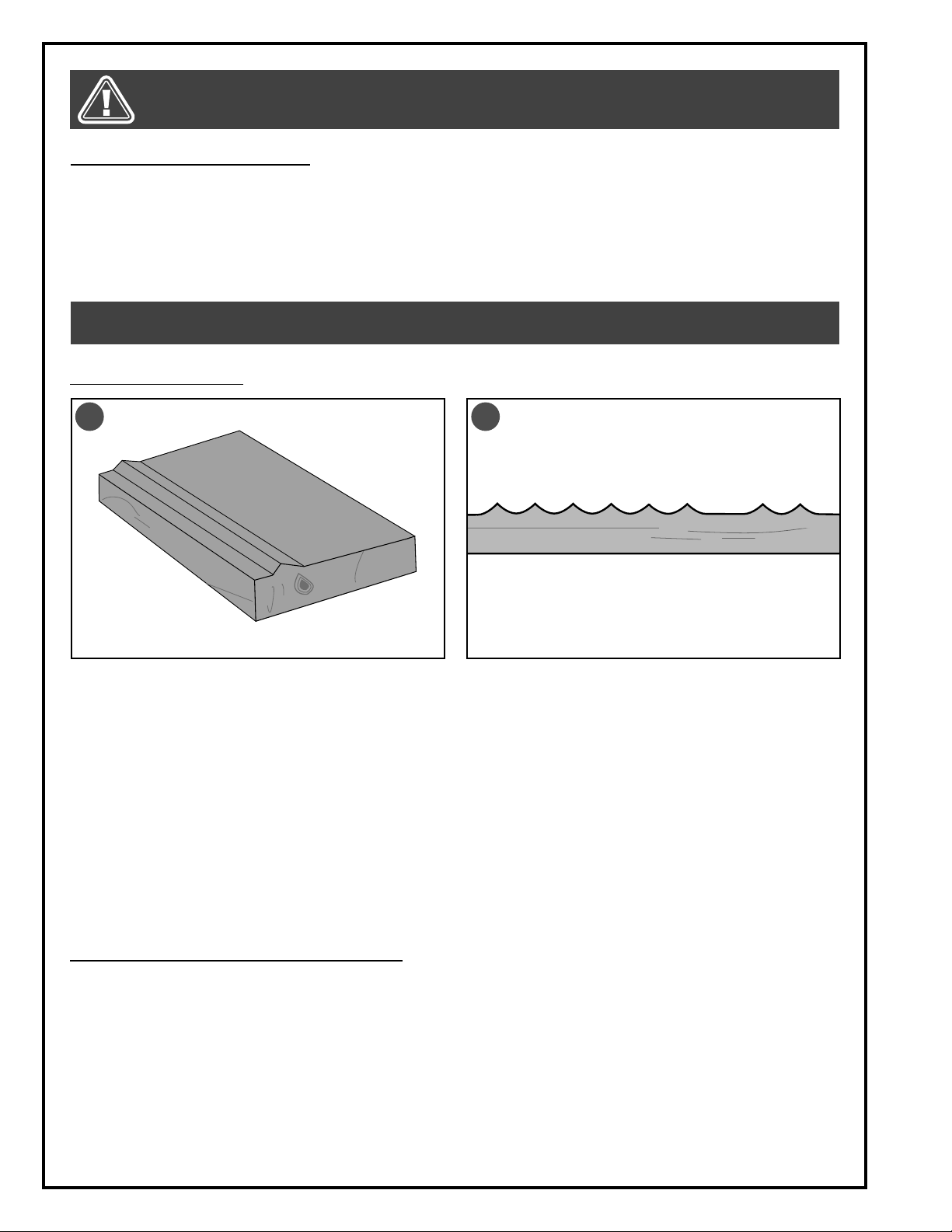
SELECTING BOARDS SUITABLE FOR PLANING
GRAIN DIRECTION
GRAIN DIRECTION
Max. 20”
Max. 8”
Min. 1/8”
Min. 6 3/4”
This planer is intended for use with solid woods or MDF
only, and should not be used to plane any other materials. The workpiece should always be fed through
the machine in the general direction of the grain in the
wood.
Before being fed through the planer all lumber should
be inspected for debris and foreign objects such as
staples or nails. Foreign objects stuck to, or embedded
in your workpiece can be ejected from the machine at
high speed and cause serious injury or damage the cutter knives.
Make sure to remove all such foreign objects from the
wood before running it through the planer. Select lumber
carefully and avoid workpieces with loose or protruding
knots. Workpieces that are twisted, severely deformed or
warped should also be avoided. Warped, twisted, damaged or fragile stock runs an increased risk of jamming in
or damaging the machine or the cutters.
There is also a much greater risk of injury to the operator or bystanders from kickback, where the workpiece is
forcefully or violently ejected from the machine due to a jam, whenever working with such damaged or warped
wood.
RESPECT THE RATED LIMITS OF THIS MACHINE. IGNORING THESE LIMITS AND FEEDING NON-COMPATIBLE STOCK INTO THIS
PLANER CAN LEAD TO SERIOUS INJURY TO THE USER OR SHOP BYSTANDERS, AND CAUSE DAMAGE TO THE WORKPIECE
AND/OR THE MACHINE. IF THE STOCK YOU WISH TO PLANE DOES NOT MEET OR COMPLY WITH THE LIMITATIONS LISTED
ABOVE, FIND ANOTHER SAFER WAY TO PERFORM THE REQUIRED TASK.
RATED LIMITS OF THIS PLANER
Maximum planing width: 20”
Minimum workpiece thickness: 1/8”
Maximum workpiece thickness: 8”
Minimum workpiece length: 6 3/4”
CHECKLIST BEFORE STARTING
• Make sure you and any assistants are wearing safe appropriate workshop attire. Roll up long sleeves, secure
long hair and remove any jewelry: watches, rings, bracelets or anything that could become caught in the moving parts, potentially causing serious injury.
• To reduce the risk of damage to the planer or the workpiece, as well as a potential for personal injury, after initial set-up as well as before each use, make sure that everything is securely installed and that all fasteners
and moving parts on this machine are locked in place before starting the machine.
• Make sure that the knives/inserts in the cutter head are properly set as explained in section “Checking/Setting the
knives”.
Make sure that the feed rollers are properly set as explained in sections “Adjusting feed roller spring tension”,
•
“Adjusting the infeed and outfeed rollers” and “Adjusting table rollers”.
• Make sure the board has been inspected and is suitable for planing as explained in section “Selecting boards
suitable for planing”.
• If multiple boards are to be planed, collect all workpieces together and set them nearby on a table or bench
within easy reach. To limit the potential for injury in the event of a kickback, avoid having to step or reach in front
of the machine to pick up the next workpiece.
• Make sure to have on safety glasses as well as hearing & respiratory protection at all times when using the
machine.
14
Page 15

MAINTENANCE
Note: It is recommended to verify the following before starting any new project. To do this will require: A straight edge, a
feeler gauge, a gauge block (see below).
GAUGE BLOCK
You may use a home made gauge block made of hardwood. The gauge block can be made by following the dimensions in the illustration. If you prefer, precision aluminum gauge blocks are available from
General International under item #30-040.
1/2"
45°
4"
1/2"
2"
MAKE SURE THE MACHINE HAS BEEN TURNED OFF AND UNPLUGGED FROM THE POWER SOURCE BEFORE PERFORMING ANY MAINTENANCE OR ADJUSTMENTS.
1½"
1/4"
3"
4"
ADJUSTING THE TABLE PARALLEL TO THE CUTTER HEAD
The cutter head has been pre-set parallel to the table
at the factory, therefore except in some rare cases
(such as important maintenance, rough transport or
handling) no further adjustments are required.
If adjustments are required follow these procedures:
1. Disconnect the machine from the power source.
2. Place the gauge block on the table directly under
the cutter head A. Raise the table until the gauge
block just touches the cutter head.
3. Move the gauge block to the opposite end of the
table B and make sure the cutter head still slightly touches the gauge block. If not, go to the next
steps.
4. Remove the access panel at the back of the machine. Remove bolt C and loosen nut D with the
a 14 mm wrench to move sprocket F and loosen
the chain. Remove the chain from the sprockets E
located on the higher side of the table.
Note: The right side was chosen for this example.
5. Turn the sprockets E clockwise by hand until the
right side of the table is the same height as the left
side.
Note: This adjustment is very sensitive and it should not be
necessary to turn the sprocket more than one or two teeth.
6. Re-install the chain, reposition the sprocket F to ten-
sion the chain, and then retighten the two bolts C
and D.
7. Re-install the rear panel.
A
B
E
F
D
C
E
15
Page 16
MAKE SURE THE MACHINE HAS BEEN TURNED OFF AND UNPLUGGED FROM THE POWER SOURCE BEFORE PERFORMING ANY MAINTENANCE OR ADJUSTMENTS.
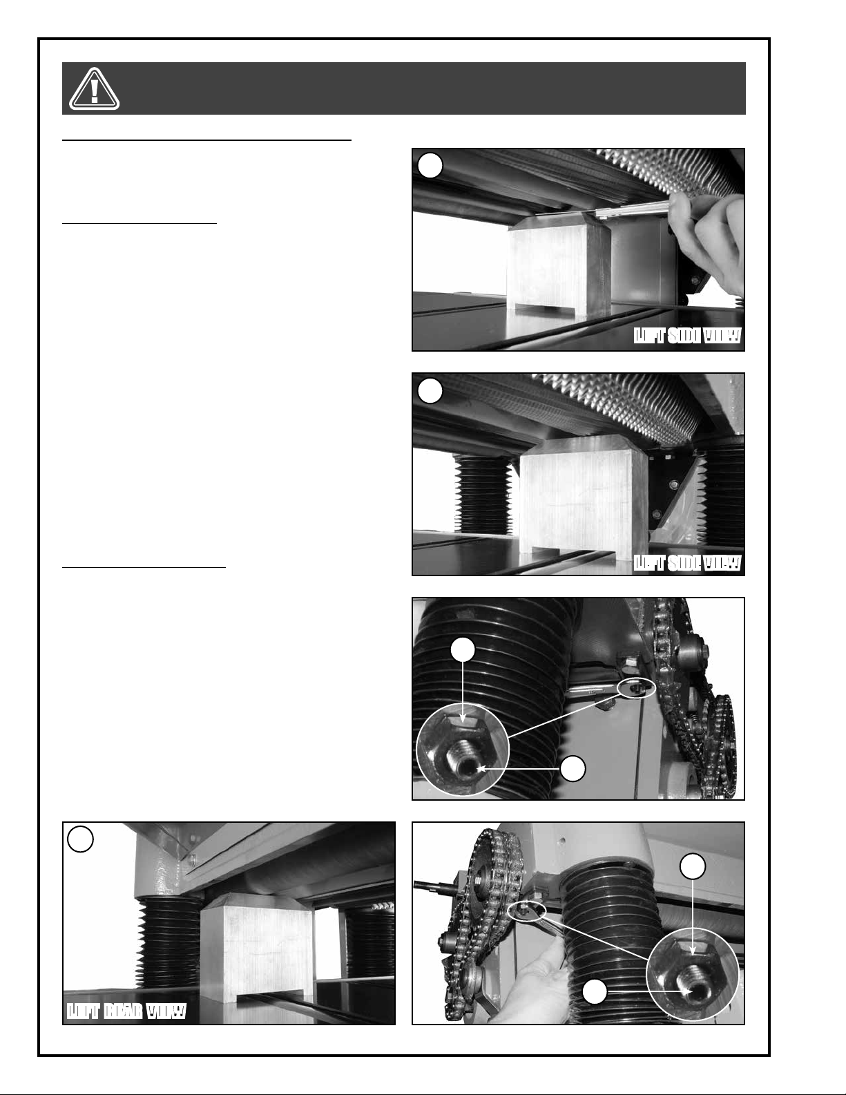
ADJUSTING THE INFEED AND OUTFEED ROLLERS
The rollers have been adjusted at the factory, therefore,
except in some rare cases (such as important maintenance, rough transport or handling) no further adjustments are required.
To adjust the infeed roller:
1. Disconnect the machine from the power source.
2. Verify that the knives are properly adjusted as
described in the section “Checking the knives/inserts”.
3. Place the gauge block on the table directly underneath the cutter head.
4. Place a 0.004” feeler gauge on top of the gauge
block, and then raise the main table until the knife/
insert just touches the feeler gauge when knife is
at the lowest point A. Do not move the table any
further until the infeed roller is adjusted.
5. Move the gauge block under the end of the infeed roller. The infeed roller should slightly touches
the top of the gauge block B. If adjustment to the
roller is necessary, loosen jam nut C with a 10 mm
wrench and turn the set screw D with a 3 mm Allen key until the infeed roller slightly touches the
gauge block. Retighten jam nut C. Repeat for the
other end of the infeed roller.
Note: For clarity, the gear box cover has been removed.
To adjust the outfeed roller:
1. Perform steps 1 to 3 above.
2. Place a 0.020” feeler gauge on top of the gauge
block, and then raise the main table until the knife
just touches the feeler gauge when knife is at the
lowest point A. Do not move the table any further
until the outfeed roller is adjusted.
3. Move the gauge block under the one end of the
outfeed roller. The outfeed roller should just touch
the top of the gauge block E. If adjustment to the
roller is necessary, loosen jam nut F with a 10 mm
wrench and turn set screw G with a 3 mm Allen
key until the outfeed roller just touches the gauge
block. Retighten jam nut F. Repeat for the other
end of the outfeed roller.
Note: For clarity, the gear box cover has been removed.
A
LEFT SIDE VIEW
B
LEFT SIDE VIEW
C
D
E
F
G
LEFT REAR VIEW
16
Page 17
MAKE SURE THE MACHINE HAS BEEN TURNED OFF AND UNPLUGGED FROM THE POWER SOURCE BEFORE PERFORMING ANY MAINTENANCE OR ADJUSTMENTS.
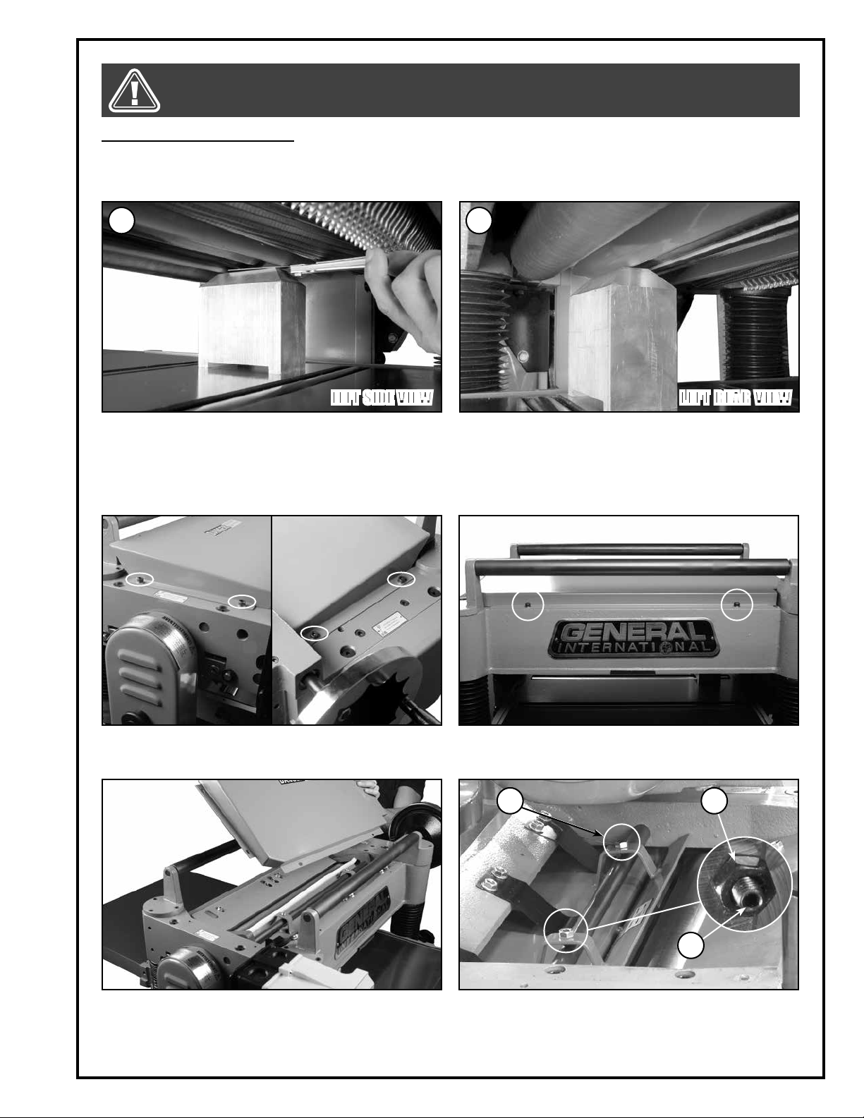
ADJUSTING THE CHIPBREAKER
The chipbreaker is located on top of the planer and extends down around the front of the cutter head. The chipbreaker raises as stock is fed through and breaks or curls the chips. The bottom of the chipbreaker must be parallel
to the knives and set 0.004” below the cutter head.
BA
LEFT SIDE VIEW LEFT REAR VIEW
1. Place the gauge block on the table directly underneath
the cutter head. Place a 0.004” feeler gauge on top of
the gauge block, and then raise or lower the main table
until the knife/insert just touches the feeler gauge when
knife is at the lowest point A. Do not move the table any
further until the chipbreaker is adjusted.
2. Move the gauge block under the end of the chipbreaker. The chipbreaker should slightly touches
the top of the gauge block B. If adjustment to the
chipbreaker is necessary, go to the next step.
3. Remove the dust chute (see section “Installing the
dust chute”), then using a 5 mm Allen key, remove
the 4 cap screws shown.
5. Remove the cover to access the chipbreaker from
above.
4. Using a 5 mm Allen key, remove the 2 screws shown.
E
C
D
F
6. Loosen the jam nut C with a 10 mm wrench and turn
the set screw D with a 3 mm Allen key until the chipbreaker just touches the gauge block. Retighten jam
nut C. Move the gauge to the other end of the chipbreaker and adjust it with E.
17
Page 18
MAKE SURE THE MACHINE HAS BEEN TURNED OFF AND UNPLUGGED FROM THE POWER SOURCE BEFORE PERFORMING ANY MAINTENANCE OR ADJUSTMENTS.
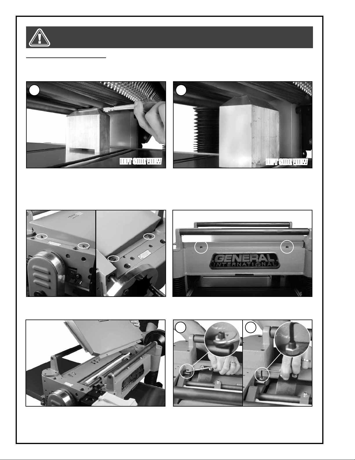
ADJUSTING THE PRESSURE BAR
The pressure bar is located on top of the planer and extends down around the front of the cutter head. The pressure
bar holds the stock against the main table as it is fed through. The bottom of the pressure bar must be parallel to
the knives and set 0.008” below the cutter head.
A B
LEFT SIDE VIEW
1. Place the gauge block on the table directly underneath
the cutter head. Place a 0.008” feeler gauge on top of
the gauge block, and then raise or lower the main table
until the knife/insert just touches the feeler gauge when
knife is at the lowest point A. Do not move the table any
further until the pressure bar is adjusted.
3. Remove the dust chute (see section “installing the
dust chute”), then using a 5 mm Allen key, remove
the 4 cap screws shown.
LEFT SIDE VIEW
2. Move the gauge block under the end of the pressure bar. The pressure bar should just touch the top
of the gauge block B. If adjustment to the pressure
bar is necessary, go to the next step.
4. Using a 5 mm Allen key, remove the 2 screws shown.
C
D
5. Remove the cover to access the pressure bar. 6. Loosen the jam nut C with a 10 mm wrench and turn
18
the set screw D with a 3 mm Allen key until the pressure bar just touches the gauge block. Retighten
jam nut C. Move the gauge to the other end of the
pressure bar and repeat the adjustment.
Page 19
MAKE SURE THE MACHINE HAS BEEN TURNED OFF AND UNPLUGGED FROM THE POWER SOURCE BEFORE PERFORMING ANY MAINTENANCE OR ADJUSTMENTS.
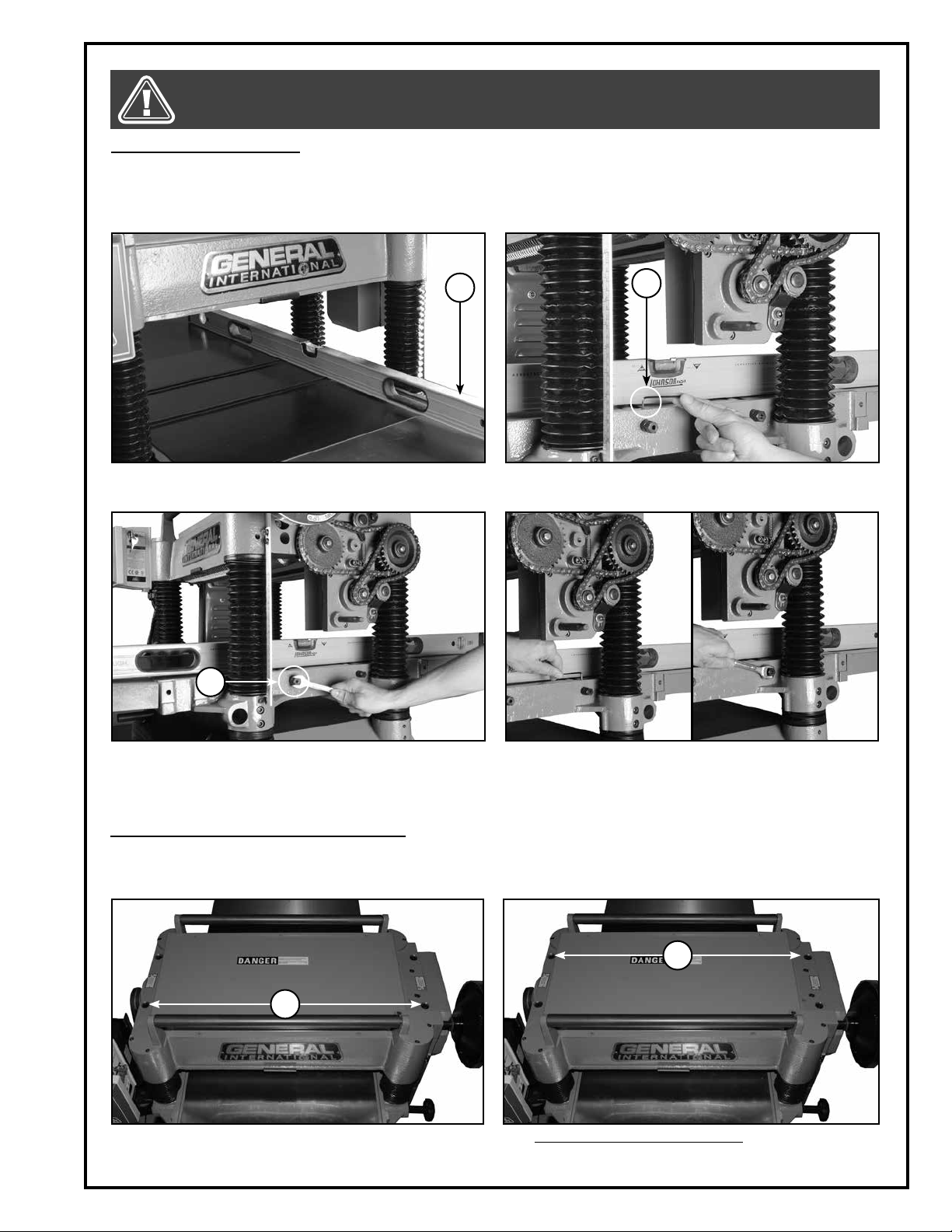
ADJUSTING TABLE ROLLERS
The table rollers are designed to help reduce friction when feeding stock through the planer. The height of the rollers can
be set based on personal preference as well as the type of stock being fed into the machine. As a general rule when
planing rough stock the rollers should be set higher, and when planing smooth stock they should be set lower.
Note: The table rollers on the planer are pre-set at the factory for average planing and parallel to the table surface.
A
1. Disconnect the machine from the power source.
Place a straight edge A across both rollers.
C
B
2. Loosen screw B with a 3 mm Allen key.
3. Rotate the eccentric shaft C with a 14 mm wrench
to raise or lower the table roller.
ADJUSTING FEED ROLLER SPRING TENSION
The feed rollers are under spring tension and this tension must be sufficient in order to feed stock smoothly and
evenly through the planer without slipping. The tension should not be too tight; this can cause damage to the
board. Tension should be even on both ends of each roller.
4. Repeat steps 2 & 3 on the other roller. After completing the adjustments, tighten the 2 screws B. Repeat
on the opposite side of the table.
E
D
1. To adjust infeed roller tension: turn screws D to the
desired tension with a 6 mm Allen key.
2. To adjust outfeed roller tension: turn screws E to the
desired tension with a 6 mm Allen key.
19
Page 20
MAKE SURE THE MACHINE HAS BEEN TURNED OFF AND UNPLUGGED FROM THE POWER SOURCE BEFORE PERFORMING ANY MAINTENANCE OR ADJUSTMENTS.
INSPECTING CUTTER HEAD KNIVES
Cutter head knives (blades) are installed in the planer at the factory. With usage and normal wear over time, it will
eventually become necessary to replace the knives.
When needed, replacement knives (sold in sets of 3) can be ordered through your local General International
distributor under part #30-305.
Observing planed workpieces as they come out of the machine and looking for signs of knife damage or wear is
the best method to help you to determine when knives are due to be changed.
TIP: TO AVOID POTENTIALLY COSTLY DOWNTIME, CONSIDER HAVING A SPARE SET OF REPLACEMENT KNIVES ON HAND AND
READY FOR USE WHEN NEEDED.
Signs to look for include:
EFFECT
BA
EXAGGERATED
FOR CLARITY
EFFECT EXAGGERATED FOR CLARITY
1. A raised ridgeline in the workpiece that runs a straight line from beginning to end of the board A. This is
generally an indication that one or all of the knives has been nicked or damaged by a foreign object
such as a nail, staple or other hard object hidden or embedded in the workpiece.
2. A slight washboard or chatter effect, B, which can be an indication of uneven knife wear causing one knife
to cut slightly deeper than the others.
3. Rough, irregular, torn or fuzzy grain on a freshly planed surface may be a sign of worn or dull blades causing the wood to tear out. Sharp blades cut crisply and leave a relatively smooth finish.
Note: fuzzy grain can also be a sign of high moisture content in the workpiece. If knives have recently been changed or
if you suspect that moisture content and not dull knives is the cause, set the workpiece aside and test by planing other
boards with known or acceptable moisture content. If the planed results using a different workpiece are smooth, then
moisture content in your wood is the problem - no adjustments can be made to the machine for this. Set the “wet” stock
aside and simply work with drier wood.
To maintain even knife wear always replace all knives each time knife replacement is required.
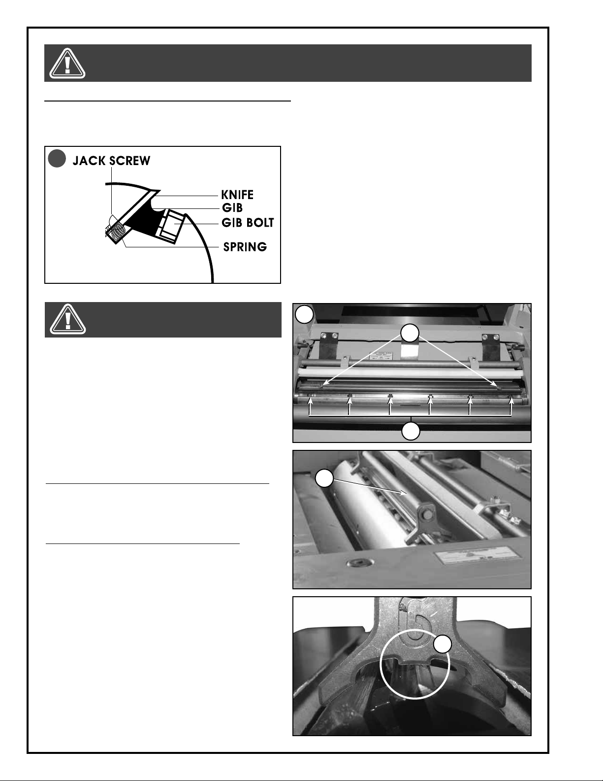
CHECKING/SETTING THE KNIVES (30-300 ONLY)
Accurate results can only be achieved when the knives are properly installed and set to the exact same height in
the cutter head.
The planer knives have been factory set to the exact same height in the cutter head. However we suggest that you
verify the knives prior to first use.
The cutter head on this unit is supplied with both adjustment springs and jack screws A providing you with two options for setting the knives.
We suggest you try each method at least once or twice and decide for yourself which method works best and
fastest for you. To verify if the knives are set properly, use a knife setting jig (included) following the steps below for
each knife.
20
Page 21
ALWAYS DISCONNECT THE MACHINE FROM THE POWER SOURCE BEFORE MAKING ANY ADJUSTMENTS. FAILURE TO HEED
THIS WARNING CAN LEAD TO SERIOUS PERSONAL INJURY. KNIVES ARE VERY SHARP. USE CARE WHEN HANDLING KNIVES.
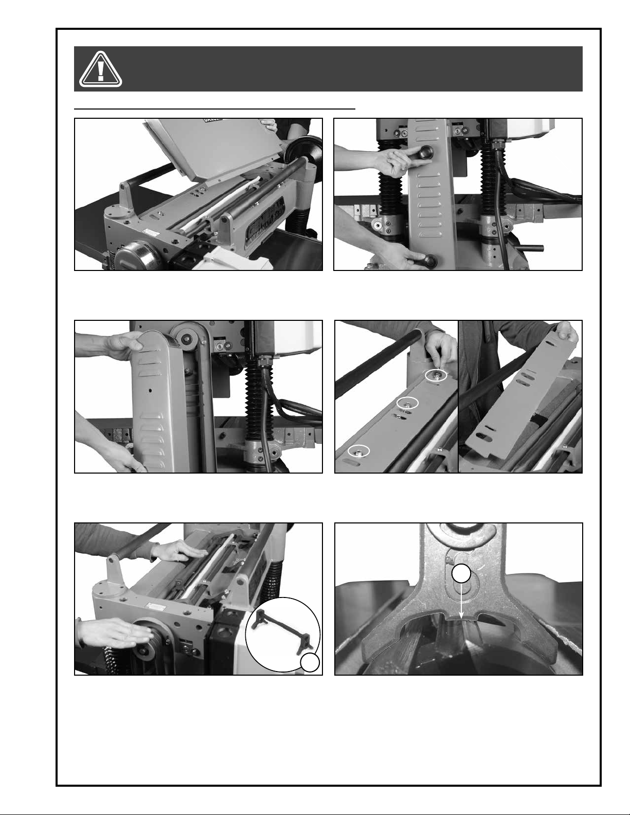
CHECKING/SETTING THE KNIVES (30-300 ONLY) CONTINUED
1. Disconnect the machine from the power source.
2. Remove the two lock knobs.
Remove the dust chute and the top cover from the
machine.
3. Remove the pulley cover. 4. Remove the three bolts using a 10 mm wrench, then
remove the guard.
B
A
5. Position one of the three knives on top by manually
turning the cutter head belt, then set the jig A on the
cutter head.
6. Ideal knife position has the jig sitting flush on the
cutter head and the knife barely touching the center reference pads on the jig B.
Note: Make sure the other knives are positioned properly.
Should any (or all) of the knives need adjusting, follow the
instructions in the next section “Knife setting or replacement”. Once the verifications are done, re-install the chip
deflector, top cover and the pulley cover.
21
Page 22
MAKE SURE THE MACHINE HAS BEEN TURNED OFF AND UNPLUGGED FROM THE POWER SOURCE BEFORE PERFORMING ANY MAINTENANCE OR ADJUSTMENTS.
KNIFE SETTING OR REPLACEMENT (MODEL 30-300 ONLY)
Properly setting all three knives is essential to achieving accurate results. Properly set knives will last longer and
also keep their edge (sharpness) longer by equally sharing the cutting workload. You may use the supplied knife
setting jig to help you set the knives to the correct height whenever re-setting or changing knives.
A
Note: If you prefer you may also find other “aftermarket”
gauges, jigs or knife setting tools that may be your liking –
ask your local tool distributor for information on any such
tools that may be available in your market.
The cutter head on this unit is supplied with both adjustment springs and jack screws A providing you with two
options for setting the knives.
We suggest you try each method at least once or twice
and decide for yourself which method works best and
fastest for you.
Tip: To avoid potentially costly downtime, consider having
a spare set of replacement knives/inserts on hand and
ready for use when needed.
KNIVES ARE VERY SHARP. USE CARE WHEN HANDLING KNIVES.
1. Refer to the previous section “Inspecting cutter
head knives” and perform steps 1 to 4 before following the instructions below.
2. Turn the cutter head pulley by hand to rotate the
cutter head to access one of the knives as shown B.
3. Loosen the 6 the gib bolts C using a 12 mm wrench
– start in the center and alternate sides. Position the
jig over the selected knife D.
Note: If replacing an old or damaged knife, loosen the
bolts until the knife can be removed and install a new
sharpened knife.
To use the adjustment springs to set the knife height:
Push the knife down with the jig so that the edge of the
knife is touching the center reference pads on the jig E.
Hold the jig down and tighten the bolts C to secure the
knife in place. Repeat for the 2 other knives.
To use the Jack Screws to set the knife height:
Use a 3 mm Allen key to turn the two screws F to raise
or lower the knife as needed until the knife touches the
center reference pads with the jig sitting flush on the
cutter head and the knife barely touching the center reference pads on the jig E. Repeat for the 2 other
knives.
6. Re-check the height on all the knives and reset if
necessary.
7. Re-install the cutter head guard, the top cover and
the dust chute, then tension the belts and re-install
the pulley cover before starting the machine.
Note: After changing or resetting the knives, the depth cut
must be readjusted.
B
F
C
D
E
22
Page 23
MAKE SURE THE MACHINE HAS BEEN TURNED OFF AND UNPLUGGED FROM THE POWER SOURCE BEFORE PERFORMING ANY MAINTENANCE OR ADJUSTMENTS.
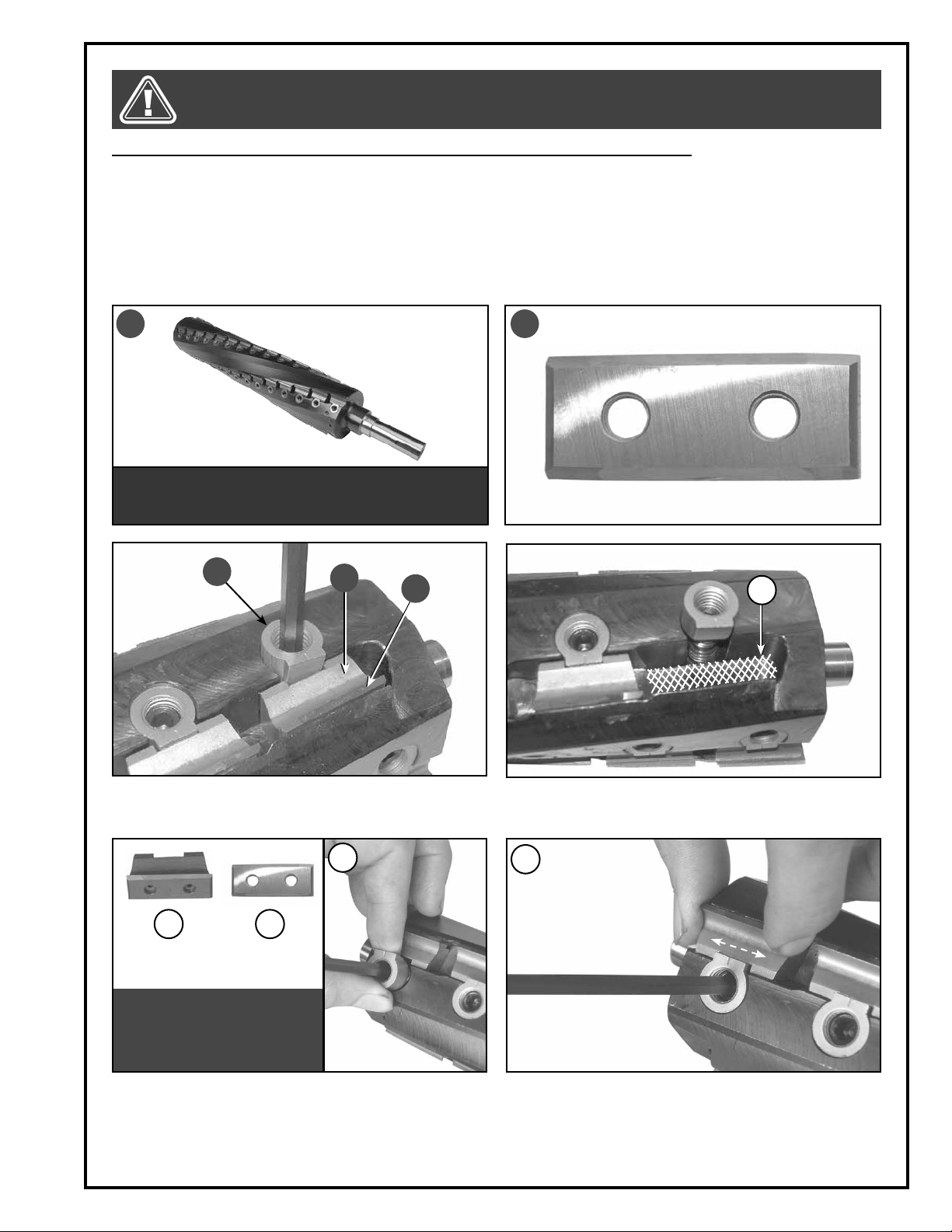
HELICAL CUTTER HEAD INSERT REVERSAL / REPLACEMENT (MODEL 30-300HC ONLY)
To be sure that the inserts are in good condition, simply make a visual inspection by manually turning the cutter
head.
There are 58 reversible carbide inserts (knives) B installed in the helical cutter head A (#30300H) at the factory. With
use and normal wear over time, it will eventually become necessary to reverse and/or replace the inserts.
To maintain even insert wear always reverse or replace all 58 inserts each time knife replacement is required. When
needed, replacement inserts B can be ordered through your local General International distributor under part
#30-443 (sold in sets of ten).
A B
NOTE: THE DISASSEMBLY OF THE CUTTER HEAD IS NOT REQUIRED FOR THIS OPERATION. THE IMAGE ABOVE IS FOR ILLUSTRATION ONLY.
C
D
E
1. Using one of the two supplied Allen keys, loosen but
do not remove the nut and screw C and remove
the knife-holder/chip breaker D and insert E.
I
G
IMPORTANT! TO PREVENT KNIFE
HEIGHT DISCREPENCIES, THE
KNIFE HOLDERS /CHIP BREAKERS AND INSERTS MUST BE
CLEAN AND FREE OF DEBRIS.
3. Thoroughly clean the knife-holders/chip breakers
G and inserts H using a lacquer thinner and small
brush. Reverse or replace the insert and re-install it
along with the knife-holder/chip breaker into the
slot, then partially retighten the nut and screw I.
H
F
2. Thoroughly clean the housing F before re-installing
a knife-holder/chip breaker and insert.
J
4. Center the knife-holder/chip breaker with the flat
edge of the nut J and fully tighten the nut and
screw. Repeat for all inserts.
23
Page 24
ALWAYS DISCONNECT THE MACHINE FROM THE POWER SOURCE BEFORE MAKING ANY ADJUSTMENTS. FAILURE TO
HEED THIS WARNING CAN LEAD TO SERIOUS PERSONAL INJURY. KNIVES ARE VERY SHARP. USE CARE WHEN HANDLING KNIVES.
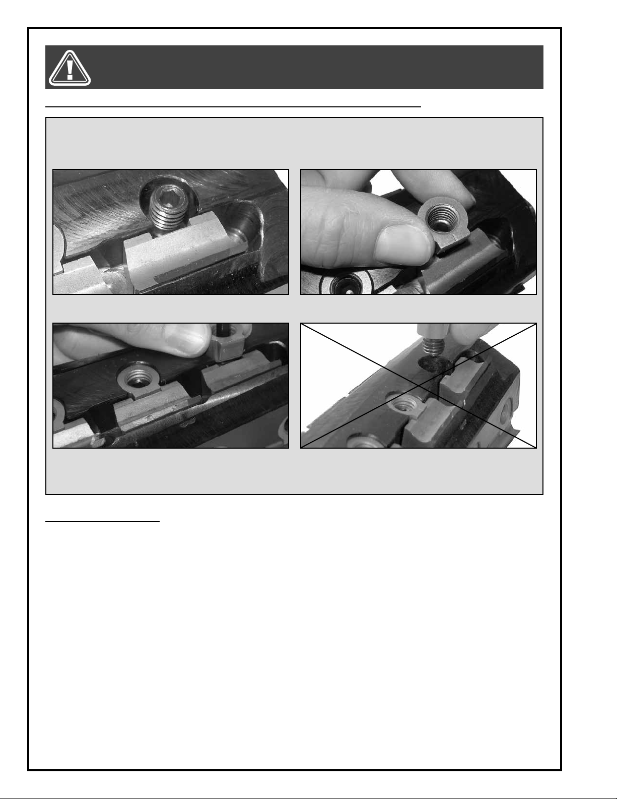
HELICAL CUTTER HEAD INSERT REVERSAL / REPLACEMENT (MODEL 30-300HC ONLY)
Important! The nut and screw that secures the knife-holder/chip breakers and inserts in the cutter head does
not have to be removed for blade reversal/replacement, only loosened. If the nuts and screws have to be replaced or if they have been removed instead of loosened, follow the instructions below to make sure that the
knife-holder/chip breakers are all secured at the same height in the cutter head.
1. Place the screw in the threaded hole but don’t
start tightening it yet.
3. Holding the nut with your fingers, tighten the screw.
This will tighten both the screw and nut simultane-
2. Place the nut on top of the screw but don’t start
tightening the screw yet.
Do not thread the nut onto the screw before tightening the
screw into the threaded hole in the cutter head.
ously.
PERIODIC MAINTENANCE
• Inspect/test the ON/OFF switch before each use. Do not operate the planer with a damaged switch; replace
a damaged switch immediately.
• Keep the machine as well the table clean and free of saw dust, woodchips, pitch or glue.Vacuum or brush off
any loose debris and wipe down the machine and the table occasionally with a damp rag.
• An occasional light coating of paste wax can help protect the table surface and reduce workpiece friction.
Ask your local distributor for suggestions on aftermarket surface cleaners, protectant and dry lubricants
based on what is readily available in your area.
• Avoid using silicon based products that may affect or react with wood finishing products such as oil, solvent
or water-based stains, varnishes and lacquers.
• Periodically inspect the power cord and plug for damage. To minimize the risk of electric shock or fire, never
operate the planer with a damaged power cord or plug. Replace a damaged power cord or plug at the first
visible signs of damage.
• The motor and cutter head bearings are sealed and permanently lubricated – no further lubrication is required.
• The drive gears, chain and elevation screws should be cleaned of woodchips, dust, debris and old grease
after every 10-15 hours of use, or as needed, depending on frequency of use. After cleaning, re-apply a gene rous coating of any common automotive bearing grease.
• Regularly inspect planed workpieces for signs of knife damage or wear and replace damaged or worn
knives immediately.
24
Page 25
MAKE SURE THE MACHINE HAS BEEN TURNED OFF AND UNPLUGGED FROM THE POWER SOURCE BEFORE PERFORMING ANY MAINTENANCE OR ADJUSTMENTS.
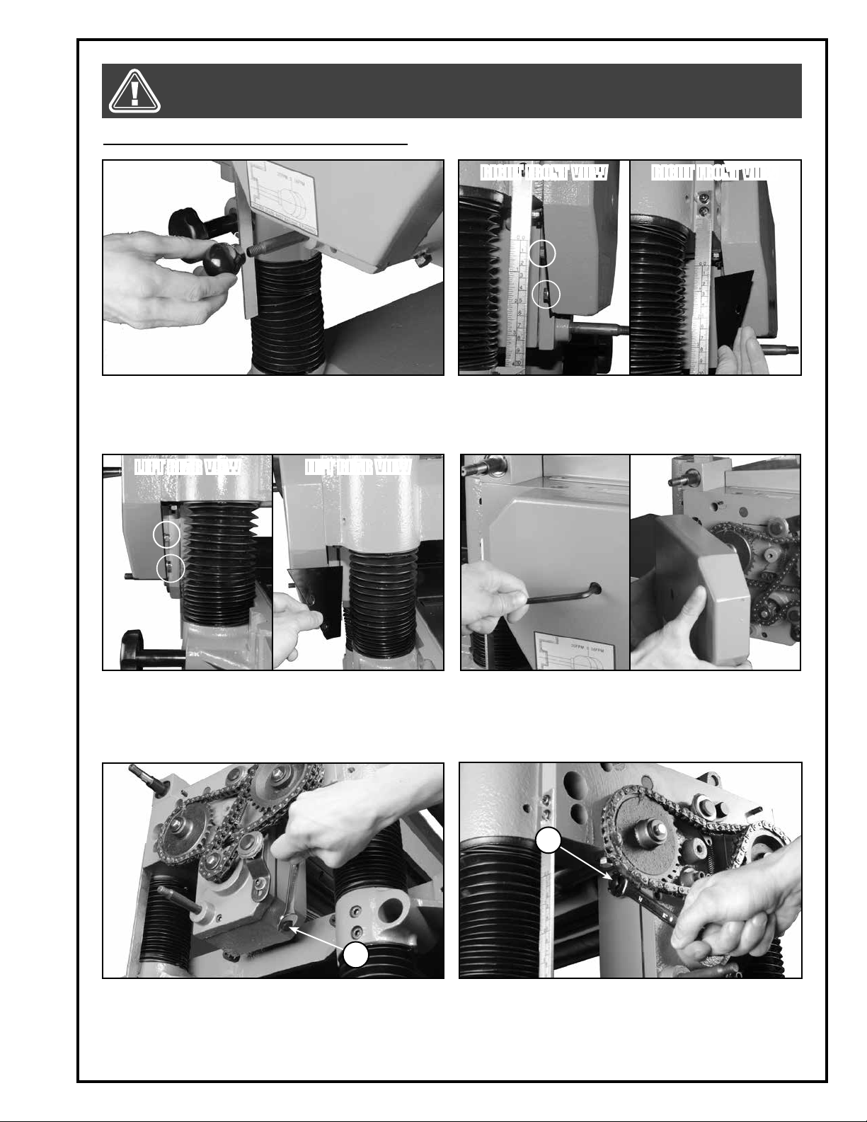
REPLACING THE GEAR BOX OIL (ONCE A YEAR):
RIGHT FRONT VIEWRIGHT FRONT VIEW
1. Remove the knob from the control feed lever by
turning it counterclockwise.
LEFT REAR VIEW LEFT REAR VIEW
3. Remove the other chain guard of the gear box cover by using a 10 mm wrench.
2. Remove the chain guard at the rear of the gear box
cover by using a 10 mm wrench.
4. Remove the gear box cover mounting screw using
a 6 mm Allen key.
A
5. Place a container under the plug A and unscrew
and remove the plug with a 14 mm wrench. Once
the gear box is drained, re-install the plug.
B
6. Remove the plug B using a 14 mm open wrench.
Fill the gear box with a 80W/90 oil until it reaches
the hole, then re-install the plug B. Re-install the gear
box cover with the chain guards before starting the
machine.
25
Page 26

MAKE SURE THE MACHINE HAS BEEN TURNED OFF AND UNPLUGGED FROM THE POWER SOURCE BEFORE PERFORMING ANY MAINTENANCE OR ADJUSTMENTS.
CLEANING THE ANTI-KICKBACK FINGERS
The anti-kickback fingers on this planer are designed
to reduce the risk of injury due to kick-back by preventing the workpiece from being violently ejected from the
machine.
In order for the anti-kickback fingers to move freely and
operate correctly, regularly clean off any dust particles
or residue left behind using a compressed air blower.
A
LUBRICATION
LUBRICATION REFERENCE CHART
REFERENCE PART TYPE OF LUBRICANT FREQUENCY TASK
Remove old lubricant and dust
A
C
B & D
ELEVATION SCREWS ALL PURPOSE OIL ONCE A MONTH
ROLLER SPRINGS ALL PURPOSE OIL
CHAINS ALL PURPOSE GREASE ONCE A MONTH
EVERY 30 HOURS OF
SERVICE
deposits by wiping with a dry rag,
then apply generous dabs of the
required lubricant.
Lubricate the spring rollers with
the required lubricant via the four
set screws.
Remove old lubricant and dust
deposits by wiping with a dry rag,
then apply generous dabs of the
required lubricant.
A
C
B
D
26
Page 27

MAKE SURE THE MACHINE HAS BEEN TURNED OFF AND UNPLUGGED FROM THE POWER SOURCE BEFORE PERFORMING ANY MAINTENANCE OR ADJUSTMENTS.
ALIGNING THE PULLEYS
1. Remove the two lock knobs from the pulley cover
and remove the cover A.
2. Using a straight edge, verify that the pulleys are
properly aligned B. If the pulleys are not aligned,
go to the next step.
3. Remove the four screws on the cover located at the
front bottom of the machine with a phillips screwdriver C, then remove the cover D. Repeat with the
cover located on the back bottom of the machine.
4. Loosen the two nuts E on the motor base using 14 mm
a wrench.
5. Loosen the two nuts F on the other side of the motor.
6. Slide the motor on its mounting plate so that the
pulleys are aligned. Once the pulleys are aligned
retighten the four nuts and re-install all the covers.
D
A
B
E
F
C
27
Page 28

MAKE SURE THE MACHINE HAS BEEN TURNED OFF AND UNPLUGGED FROM THE POWER SOURCE BEFORE PERFORMING ANY MAINTENANCE OR ADJUSTMENTS.
ADJUSTING BELT TENSION
1. Loosen the two nuts using a 17 mm wrench. 2. Check the belt tension by pushing the belt with your
finger. The belt should not move more than 1/2”. If
the belt moves more than 1/2”, go to the next step.
3. Using a phillips screwdriver, remove the four screws
on the cover located at the front bottom of the machine, then remove the cover to access the motor.
REPLACING THE BELTS
B
A
4. To tighten the belts, turn the two nuts A counter-
clockwise using a 17 mm wrench and turn the two
nuts B counterclockwise until the required tension is
achieved.
To loosen the belts, turn the two nuts B clockwise
using a 17 mm wrench until the required tension
is achieved. Tighten the nuts A against the motor
plate.
1. Remove the two lock knobs from the pulley cover,
then remove the cover.
28
2. Remove the four screws on the cover located at the
front bottom of the machine with a phillips screwdriver C.
Page 29

MAKE SURE THE MACHINE HAS BEEN TURNED OFF AND UNPLUGGED FROM THE POWER SOURCE BEFORE PERFORMING ANY MAINTENANCE OR ADJUSTMENTS.
REPLACING THE BELTS
A
3. Remove the cover to access the motor. 4. Loosen without removing the two nuts A using a 17
mm wrench.
5. Place a piece of wood under the motor base.
6. While pressing on the wood to pivot up the motor
up, remove all the belts from the motor pulley. Install
the new belts, then adjust the tension belts (see section “Ajusting the belt tension”). Re-install the cover
before starting the machine.
ADJUSTING THE GRADUATED SCALE
The graduated scale is adjusted at the factory and under normal circumstances should not require adjustment
upon initial installation. However with use over time, it may become necessary to re-adjust the graduated scale.
1. Plane a board then measure its thickness to verify
that it corresponds with the measure indicated by
the graduated scale. If not, go to the next step.
B
2. Loosen the two screws with a Phillips screwdriver
then position the scale so that it indicates the thickness of the board you have just planed. Once the
adjustment is done, retighten the screws.
29
Page 30

RECOMMENDED OPTIONAL ACCESSORIES
Here is a sampling of optional accessories available from your local General International dealer that can be
used with this product. For more information about our products, please visit our website at www.general.ca
Item #30300H
20” MAGNUM” HELICAL CUTTER HEAD
DUST COLLECTORS
We offer a wide selec
tion of top quality dust
collectors to suit all your
shop needs. Dust col
lectors contribute to a
cleaner more healthful
workshop environment.
Item #30-050
DIAL-GAUGE MICROMETER FOR PLANER
AND JOINTER KNIFE
ALIGNMENT
Precision built, easy to adjust, mounted on enamel
finished alloy steel. Designed to rest squarely on
the cutter head for fast accurate knife alignment. Dial
is easy to read and adjust.
4 rows, total: 58 inserts.
-
-
Item #
30-443
SET OF 10 CUTTER HEAD
INSERTS
For “Magnum” helical cutter head.
Item #50-150, #50-170 &
#50-167S
ROLLER STANDS
We offer a selection of
roller stands for added
in-feed or out-feed sup
port when working with
longer stock.
Item #30-040
CUTTER HEAD – TABLE
ALIGNMENT BLOCKS
Aluminum guide block
used to align the cut
ter head parallel to the
table (set of 2).
Item #
30-444
-
-
INSERT SCREWS
For carbide inserts on
“Magnum” helical cutter
head.
30
Item #30-025
MAGNETIC, MICRO-ADJUSTABLE KNIFE ALIGNMENT GAUGE
Set of two gauges. Suitable for all planer knives from
6” – 26” in length.
Item #30-305
REPLACEMENT KNIVES
Set of 3 20” hi-speed steel knives
Page 31

DIAGRAM
HEADSTOCK
87N
86
95
31
Page 32

PARTS LIST
HEADSTOCK
IMPORTANT: When ordering replacement parts, always give the model number, serial number of the
machine and part number. Also a brief description of each item and quantity desired.
PART # DESCRIPTION SPECIFICATIONS QTY
30300-01 HEAD CASTING 1
30300-02 SET SCREW M10 X 1.5P -12 8
30300-03 CUTTER HEAD 1
30300-04 HEX HEAD BOLT M8 X 1.25P -10 18
30300-05 KNIVES 3
30300-06 KNIFE LOCKING BAR 3
30300-07 HEX HEAD BOLT 6
30300-08 KNIFE GAUGE 14
30300-09 HEX HD. SCREW W/WASHER 14
30300-10 HEX HD. SCREW W/WASHER 4
30300-11 CAP SCREW 2
30300-12 BEARING 6206 2NSE 1
30300-13 KEY 8 X 8 X 35 1
30300-14 MACHINE PULLEY 1
30300-15 WASHER 8 X 30 X 3T 2
30300-17 MOTOR PULLEY 1
30300-18 INFEED ROLLER 1
30300-19 BUSH 4
30300-20 SPRING 4
30300-21 SCREW M22 X 1.5P-20 4
30300-22 PLATE 1
30300-23 HEX HEAD BOLT M8 X 1.25P - 20 8
30300-24 SET SCREW M6 X 1.0P - 16 4
30300-25 NUT M6 X 1.0P 8
30300-26 KEY 5 X 5 X 22 2
30300-27 SPROCKET 31T 1
30300-28 WASHER 6.2 X 22 X 3 2
30300-29 HEX HEAD BOLT M6 X 1.0P 2
30300-30 OUTFEED ROLLER 1
30300-31 SPROCKET 1
30300-32 SHAFT 1
30300-33 RETAINING RING STW-12 1
30300-34 CHIP BREAKER 1
30300-35 NUT M12 X 1.75P 2
30300-36 PLATE SPRING 3
30300-37 WASHER 6.6 X 13 X 1.0 14
30300-38 HEX HEAD BOLT M6 X 1.0P X 12 11
30300-39 SHAFT 1
30300-40 BRACKET 2
30300-41 PRESSURE PLATE 1
30300-42 SPRING WASHER 8.2 X 15.4 X 2 2
30300-43 SHAFT 2
30300-45 SET SCREW M6 X 1.0P -20 2
30300-46 PLATE SPRING 0.6T 3
30300-47 CHIP DEFLECTOR PLATE 1
30300-48 ANTI-KICK FINGER 86
30300-49 COLLAR 86
30300-50 SHAFT 1
30300-51 RETAINING RING ETW-15 2
30300-52 CUT LIMITER PLATE 1
30300-53 FLAT HD. MACH SCREW M5 X 0.8P X 12 2
30300-54 UPPER COVER 1
30300-55 GASKET 1
32
Page 33

PARTS LIST
HEADSTOCK
IMPORTANT: When ordering replacement parts, always give the model number, serial number of the
machine and part number. Also a brief description of each item and quantity desired.
PART # DESCRIPTION SPECIFICATIONS QTY
30300-56 COLLECTOR TUBE 1
30300-57 ROLLER STAND 3
30300-58 ROLLER 2
30300-59 CAP SCREW M6 X 1.0P - 16 9
30300-60 WORM GEAR BOX 1
30300-61 CAP SCREW M6 X 1.0P - 50 3
30300-62 WORM 1
30300-63 BEARING 6201 Z 1
30300-64 RETAINING RING RTW-32 1
30300-65 KEY 4 X 4 X 10 1
30300-66 HAND WHEEL 1
30300-67 WASHER 13 X 28 X 3 1
30300-68 HANDLE 1
30300-69 SCALE 1
30300-71 CUT LIMIT POINTER 1
30300-72 WASHER 8.2 X 23 X 2T 2
30300-73 COVER 1
30300-74 SPRING PIN Ø6 X 20 2
30300-75 SAFETY HATCH 1
30300-76 PAN HD. SCREW M6 X 1.0P - 12 6
30300-77 SAFETY HATCH 1
30300-78 CAP SCREW M8 X 1.25P - 40 1
30300-79 PULLEY GUARD 1
30300-80 BOLT 2
30300-82 NUT 5/16” - 18NC 2
30300-83 BELT 3
30300-84 PULLEY COVER 3
30300-85 NUT 5/16” - 18NC 1
30300-86 SWITCH BOARD 2
30300-87N MAG SWITCH (ITEM #85-285) 1
30300-89 NAME PLATE 2
30300-90 RIVET 2 X 5 1
30300-91 CHAIN 06B X 67P 4
30300-92 RELIEF BUSHING 1
30300-93 POWER SUPPLY WIRE 1
30300-95 CAP SCREW M6 X 1.0P - 12 2
30300-96 SET SCREW M8 X 1.25P - 8 11
30300-97 LABEL 1
30300-98 COLLAR 1
30300-99 SHAFT 1
30300-100 IDLE PULLEY 1
30300-101 BRACKET 1
30300-102 SHAFT 1
30300-103 HANGER 1
30300-104 SPRING 1
30300-105 WASHER 8.2 X 22 X 3T 1
30300-106 BRACKET M6 X 1.0P X 12 2
30300-107 CAP SCREW M6 X 1.25 X 18 1
30300-108 LABEL 2
30300-109 WARNING LABEL 1
30300-110 CAP SCREW M5 X 0.8 X 10 1
33
Page 34
DIAGRAM
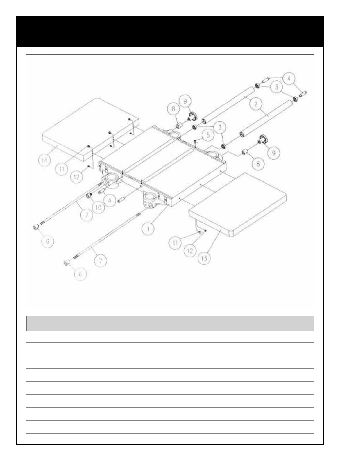
TABLE
IMPORTANT: When ordering replacement parts, always give the model number, serial number of the
machine and part number. Also a brief description of each item and quantity desired.
PART # DESCRIPTION SPECIFICATIONS QTY
30300-01 T MIDDLE TABLE 1
30300-02 T ROLLER 2
30300-03 T BEARING 6201Z 4
30300-04 T ECCENTRIC SHAFT 4
30300-05 T SET SCREW M6 X 1.0P - 12 4
30300-06 T LOCK BAR 2
30300-07 T LOCKING BOLT 2
30300-08 T LOCKSMITH 2
30300-09 T KNOB 2
30300-10 T CAP SCREW M8 X 1.25P - 16 8
30300-11 T HEX HD. SCREW M8 X 1.25P -25 6
30300-12 T SET SCREW M8 X 1.25P X 20 6
30300-13 T EXTENSION WING 1
30300-14 T EXTENSION WING 1
34
Page 35
DIAGRAM
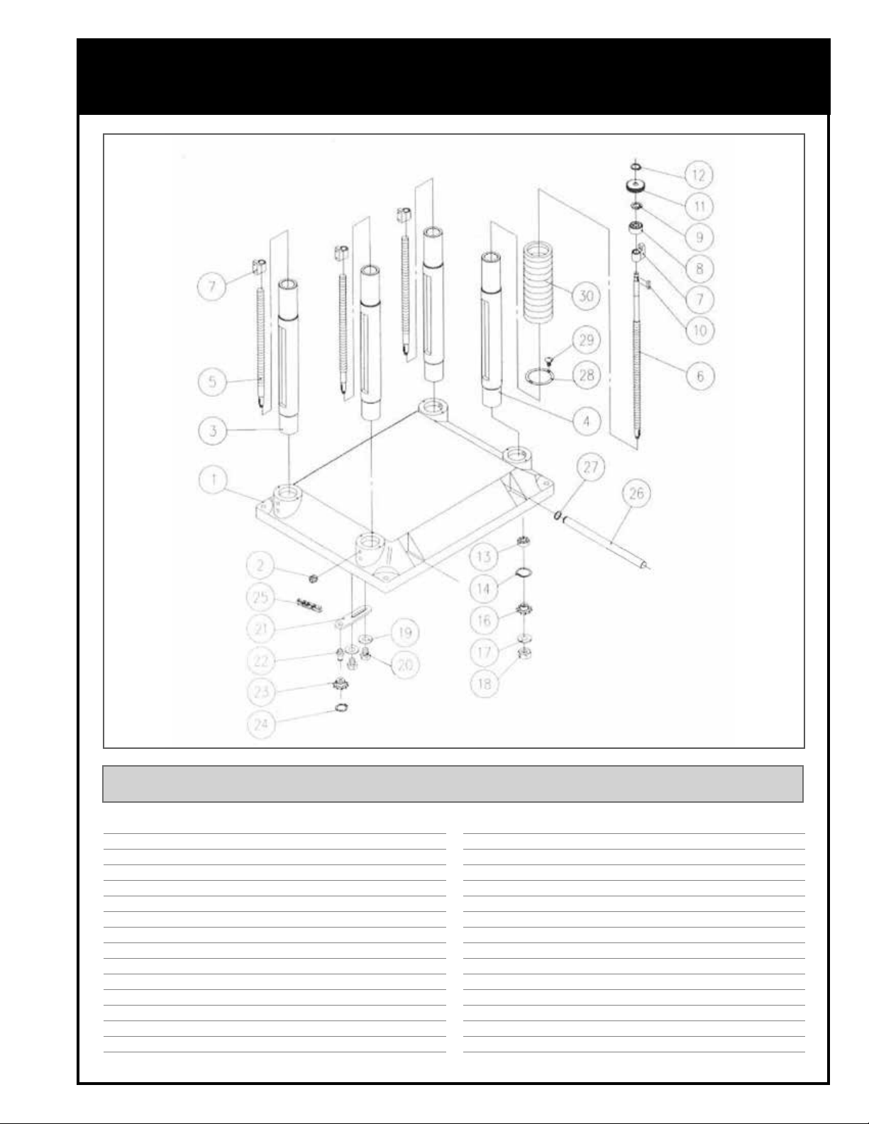
BASE
IMPORTANT: When ordering replacement parts, always give the model number, serial number of the
machine and part number. Also a brief description of each item and quantity desired.
PART # DESCRIPTION SPECIFICATIONS QTY
30300-01 B BASE 1
30300-02 B SET SCREW M10 X 1.5P -12 8
30300-03 B COLUMN 3
30300-04 B COLUMN 1
30300-05 B LEAD SCREW 2
30300-06 B LEAD SCREW 1
30300-07 B NUT 4
30300-08 B BUSH 1
30300-09 B RETAINING RING RTW-38 1
30300-10 B KEY 4 X 4 X 10 1
30300-11 B GEAR 24T 1
30300-12 B RETAINING RING STW-12 1
30300-13 B BEARING 6202 4
30300-14 B RETAINING RING RTW-35 4
30300-16 B SPROCKET 10T 4
30300-17 B WASHER 3/8” X 20 X 1.5 4
30300-18 B NUT M10 X 1.25P 4
30300-19 B WASHER Ø8.2 X 22 X 3 2
30300-20 B HEX HEAD BOLT M18 X 1.25P-25 2
30300-21 B BRACKET 1
30300-22 B SHAFT 1
30300-23 B SPROCKET 10T 2
30300-24 B RETAINING RING STW-15 1
30300-25 B CHAIN N0. 40 X 16 6P 1
30300-26 B CRANE POST 4
30300-27 B RETAINING RING ETW-19 4
30300-28 B PIPE BAND 16
30300-29 B MACHINE SCREW M5 X 0.8P - 10 32
30300-30 B EXPANSION BEN 8
35
Page 36
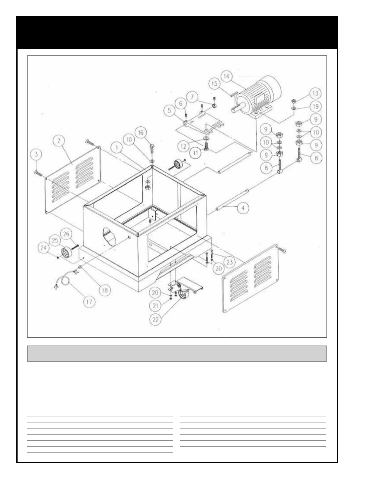
DIAGRAM
STAND
IMPORTANT: When ordering replacement parts, always give the model number, serial number of the
machine and part number. Also a brief description of each item and quantity desired.
PART # DESCRIPTION SPECIFICATIONS QTY
30300-01 S STAND 1
30300-02 S COVER 2
30300-03 S MACHINE SCREW M6 X 1.0P - 20 8
30300-04 S BAR 2
30300-05 S MOTOR MOUNT 1
30300-06 S SET SCREW M8 X 1.25P - 8 4
30300-07 S COLLAR 1
30300-08 S ADJUSTING BOLT 2
30300-09 S HEX NUT M12 X 1.75P 8
30300-10 S WASHER 1/2 X 28 X 3 12
30300-11 S HEX HD. SCREW M8 X 1.25P - 25 4
30300-12 S WASHER 5/16” X 23 X 2 8
30300-13 S NUT M8 X 1.25P 6
36
30300-14 S MOTOR 1
30300-15 S KEY 5 X 5 X 30 1
30300-16 S HEX HD. SCREW M12 X 1.75P - 60 4
30300-17 S POWER SUPPLY WIRE 1
30300-18 S RELIEF BUSHING 1
30300-19 S WASHER 5/16” X 16 X 1.8 8
30300-20 S HEX SCREW 2
30300-21 S HEX NUT M8 X 1.25P 2
30300-22 S PEDAL ASSY 1
30300-23 S HEX SCREW M8 X 1.25P X 60 2
30300-24 S NUT M8 X 1.25P 2
30300-25 S WHEEL 2
30300-26 S SCREW M8 X 1.25P X 60 2
Page 37
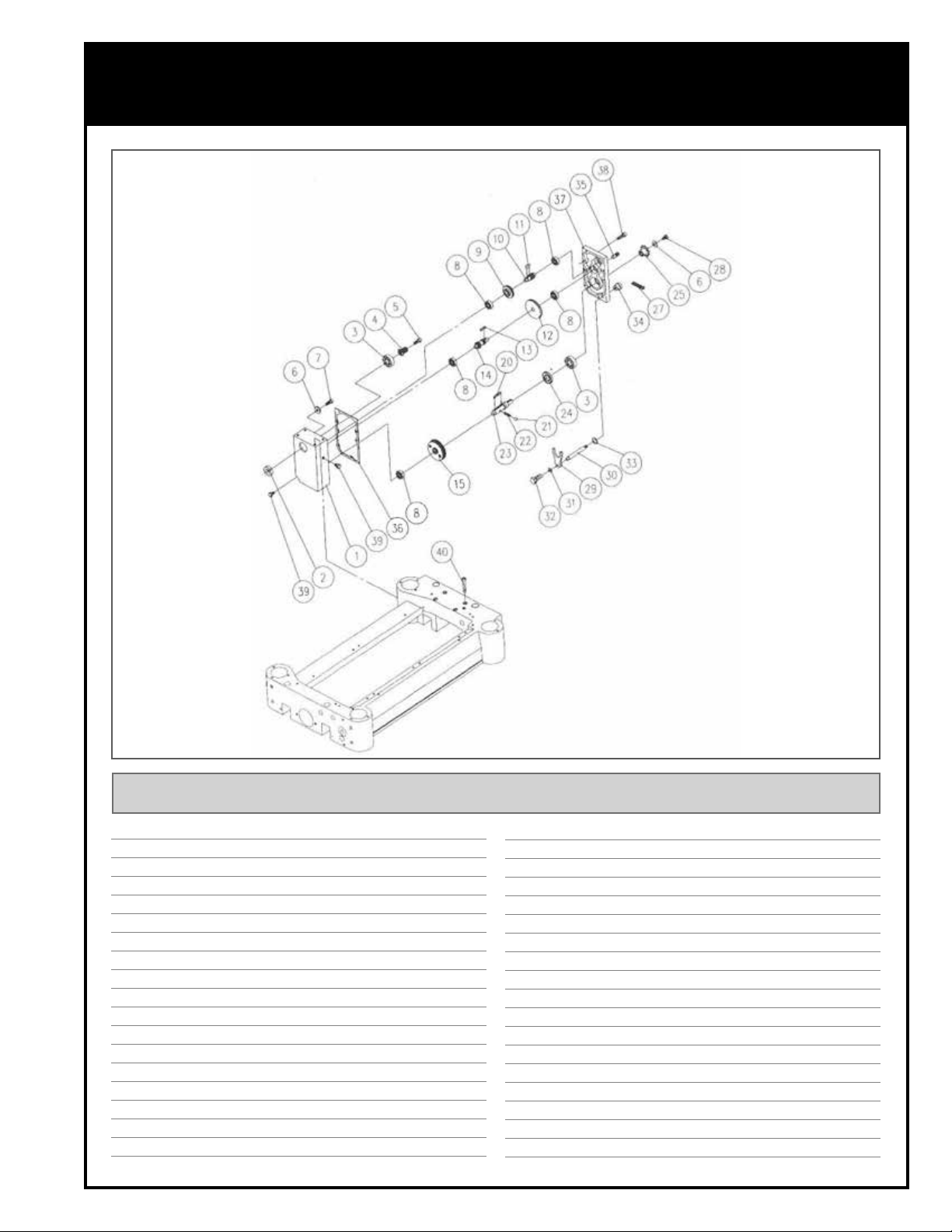
DIAGRAM
GEAR BOX
IMPORTANT: When ordering replacement parts, always give the model number, serial number of the
machine and part number. Also a brief description of each item and quantity desired.
PART # DESCRIPTION SPECIFICATIONS QTY
30300-01 G GEAR BOX 1
30300-02 G OIL SEAL 28 X 40 X 8 1
30300-03 G BEARING 6204 ZZ 2
30300-04 G GEAR 1
30300-05 G CAP SCREW M6 X 1.0P - 25 1
30300-06 G WASHER 6.2 X 22 X 3T 2
30300-07 G CAP SCREW M6 X 1.0P - 12 1
30300-08 G BEARING 0.6201 5
30300-09 G GEAR 1
30300-10 G SHAFT 1
30300-11 G KEY 5 X 5 X 12 1
30300-12 G GEAR 1
30300-13 G KEY 5 X 5 X 10 2
30300-14 G SHAFT 1
30300-15 G GEAR 1
30300-20 G KEY 6 X 6 X 40 3
30300-21 G BALL 6 1
30300-22 G SPRING 1
30300-23 G SHAFT 1
30300-24 G OIL SEAL SC24 1
30300-25 G SPROCKET 1
30300-27 G CHAIN 06B X 47 1
30300-28 G HEX HEAD BOLT M6 X 1.0P - 16 1
30300-29 G CLUTCH 1
30300-30 G HANDLE 1
30300-31 G WASHER 6.3 X 13 X 1.5T 1
30300-32 G HEX HEAD BOLT M6 X 1.0P - 12 1
30300-33 G OIL RING P-12 1
30300-34 G KNOB 1
30300-35 G PIN 8 X 20 2
30300-36 G PACKING PIECE 1
30300-37 G COVER 1
30300-38 G CAP SCREW M6 X 1.0P - 25 5
30300-39 G OIL PLUG PT1 / 4-19 2
30300-40 G CAP SCREW M8 X 1.25P - 50 4
37
Page 38
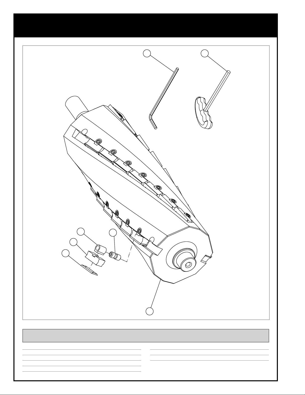
HELICAL CUTTER HEAD - #30300H
30-300HC ONLY
7
6
3
4
5
IMPORTANT: When ordering replacement parts, always give the model number, serial number of the
machine and part number. Also a brief description of each item and quantity desired.
PART # DESCRIPTION SPECIFICATIONS QTY
30300H-01 CUTTER HEAD 1
30300H-02 INSERT SCREW (ITEM #30-444) 48
30300H-03 NUT 48
30300H-04 KNIFE-HOLDER / CHIPBREAKER 48
*Sold in packs of ten
38
2
1
30300H-05 INSERT (ITEM#30-443)*
30300H-06 “T” HANDLE ALLEN WRENCH 5 MM 1
30300H-07 ALLEN KEY 5 MM 1
30X12X1.5MM
48
Page 39

NOTES
Page 40
8360 Champ-d’Eau, Montreal (Quebec) Canada H1P 1Y3
Tel.: (514) 326-1161
Fax: (514) 326-5565 - Parts & Service / (514) 326-5555 - Order Desk
orderdesk@general.ca
www.general.ca
Follow us:
 Loading...