


GE AZ41E09DAP, AZ61H12DAB, AZ41E12EAB, AZ61H07DAC, AZ61H07EAB User Manual [nl]
...Air Conditioners
Zoneline®
GEAppliances.com
Safety Instructions . . . . . . . . . . . . .2
Operating Instructions
Air Direction . . . . . . . . . . . . . . . . . . . . . . .4
Auxiliary Controls . . . . . . . . . . . . . . . .5–8
Controls . . . . . . . . . . . . . . . . . . . . . . . . . . .3
To Remove the Room Cabinet . . . . . .4
Ventilation Control . . . . . . . . . . . . . . . . .4
Care and Cleaning
Air Filters . . . . . . . . . . . . . . . . . . . . . . . . .10
Base Pan . . . . . . . . . . . . . . . . . . . . . . . . . .9
Outdoor Coils . . . . . . . . . . . . . . . . . . . . . .9
Room Cabinet and Case . . . . . . . . . . . .9
Ventilation Filter . . . . . . . . . . . . . . . . . . . .9
Installation Instructions
Electrical Connection . . . . . . . . . .13–16
Installing the Zoneline . . . . . . . . .17, 18
Optional Drain Kit . . . . . . . . . . . . . . . . .19
Preparation . . . . . . . . . . . . . . . . . . . . . . .11
Replacing an Existing Unit? . . . . . . . .12
Troubleshooting Tips . . . . .20, 21
Normal Operating Sounds . . . . . . . . .22
Owner’s Manual and
Installation Instructions
Heat/Cool Model 4100
Heat Pump Model 6100
Español
For a Spanish version of this manual, visit our Website at www.zoneline.com/literature.
Para consultar una version en español de este manual
de instrucciones, visite nuestro sitio de internet www.zoneline.com/literature.
Français
For a French version of this manual, visit our Website at www.zoneline.com/literature.
Pour un version français de
ce manuel d’utilisation, veuillez visiter notre site web à l’adresse www.zoneline.com/literature.
Consumer Support
Consumer Support . . . . . . . .Back Cover
Warranty . . . . . . . . . . . . . . . . . . . . . . . . .23
Write the model and serial numbers here:
Model # __________________
Serial # ____________________
Find these numbers on a label behind the room cabinet on the base pan.
TINSEA576JBRZ 49-7612-3 1-13 GE
Safety Instructions
Operating Instructions
Care and Cleaning
Troubleshooting Tips
Consumer Support
IMPORTANT SAFETY INFORMATION.
READ ALL INSTRUCTIONS BEFORE USING.
 WARNING!
for your safety, the information in this manual must be followed to minimize the risk of fire or explosion, electric shock, or to prevent property damage, personal injury, or loss of life.
safEty PRECautions
■This Zoneline must be properly installed in accordance with the Installation Instructions before it is used. See the Installation Instructions in the back
of this manual.
■Replace immediately all electric service cords that have become frayed or otherwise damaged. A damaged power supply cord must be replaced with a new power supply cord obtained from the manufacturer and not repaired.
Do not use a cord that shows cracks or abrasion damage along its length or at either the plug or connector end.
■Unplug or disconnect the Zoneline at the fuse box or circuit breaker before making any repairs.
NOTE: We strongly recommend that any servicing be performed by a qualified individual.
■These R410A air conditioning systems require contractors and technicians to use tools, equipment and safety standards approved for use with this refrigerant. DO NOT use equipment certified for R22 refrigerant only.
Replacing an existing unit?
For details, see the Installation Instructions in this manual.
REad and follow tHis safEty infoRMation CaREfully.


 SAVE THESE INSTRUCTIONS
2
About the controls on your Zoneline. |
GEAppliances.com |
|||
|
|
|
|
|
|
|
|
|
|
|
|
|
|
|
|
|
|
|
|
|
|
|
|
|
|
|
|
|
|
|
|
|
|
|
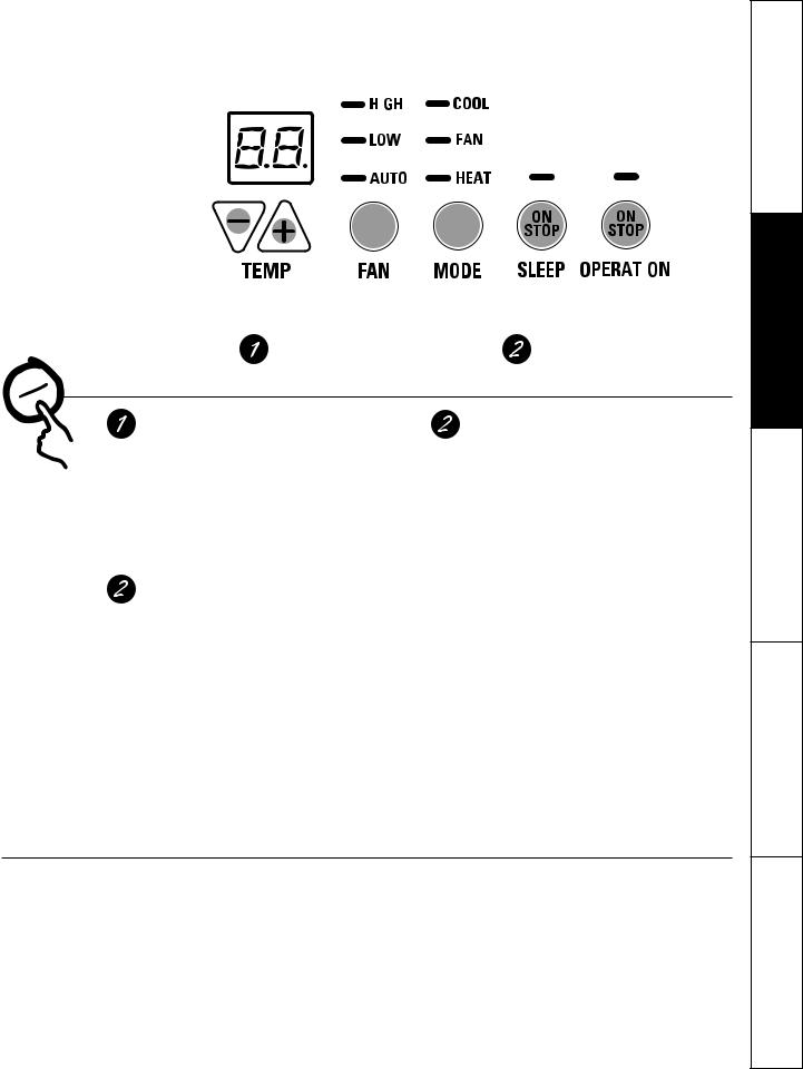
TEMP CONTROL FAN, MODE & SLEEP OPERATION
Controls
Temp Control
The temp control is used to maintain the room temperature. The compressor will cycle on and off to keep the room at the same level
of comfort.
Press the ▲ pad to raise the temperature. Press the ▼ pad to lower the temperature.
NOTE: The display shows the set temperature, not the room temperature.
Sleep
Press to set the air conditioner to run for 8 hours before it automatically returns to the previous setting.
When in the cooling mode and the sleep timer is set, the set temperature will automatically increase 2°F after the second hour then 1°F each hour over the next two hours. Also, the fan speed will change to low. When in the heating mode, the set temperature will decrease in the same manner.
To cancel the sleep mode, press the MODE pad or the SLEEP pad a second time.
Fan, Mode and Operation Control
FAN—Sets the fan operation for HIGH, LOW or AUTO speed. When set at AUTO, it automatically switches between LOW and HIGH as room temperature changes.
MODE—COOL—For cooling
FAN—For fan-only operation HEAT—For heating
OPERATION—ON/STOP—Turns the unit on or off. Power remains connected to the Zoneline. The Freeze/Heat Sentinel features still function if active.See the freezer/Heat sentinel section on page 6.
NOTE: the temperature display will flash to indicate a possible unit malfunction. set
operation control to STOP and then restart the unit. if the flashing light reappears within 30 minutes, call for service.
Quick Heat Recovery
Activates each time the thermostat is switched from STOP or COOL mode to HEAT mode. Electric heaters are energized until the thermostat set point
is reached. On heat pump models, the heat pump operation will resume at the next call for heat.
About Your Heat Pump (6100 Series only)
Heat pumps can save money by removing heat from the outside air—even when the outside temperature is below freezing—and releasing that heat indoors.
To get the best performance from your heat pump, don’t change the room thermostat very often. Raising the heat setting 2–3 degrees will cause the Zoneline to use its electric heating elements in
order to reach the new temperature setting quickly.
There is a 3-minute minimum compressor
run time at any setting to prevent short cycling.
The indoor fan motor starts before the compressor and stops after the compressor cycles off.
When the outdoor temperature is lower than 25°F, heat is provided by the electric heater in the air conditioner instead of by the heat pump.
The electric heating elements use much |
|
more electricity than heat pumps and cost |
3 |
more to operate. |
Instructions Safety
Instructions Operating
Cleaning and Care
Tips Troubleshooting
Support Consumer

Safety Instructions
Operating Instructions
Care and Cleaning
Troubleshooting Tips
Consumer Support
Other features of your Zoneline.
Ventilation Control |
Open |
Closed |
|
position |
|||
|
position |
||
NOTE: two shipping screws must be removed |
|
||
|
|
||
from the vent door before use. see the installation |
|
|
|
instructions in the back of this manual. if you do not |
|
|
|
plan to use the ventilation feature, leave these two |
|
|
|
screws in place. |
|
|
The ventilation control lever is located at the middle left side of the Zoneline unit, behind the room cabinet.
When set at the closed position, only the air inside the room is circulated and filtered.
When set at the open position, some outdoor |
Vent control |
|
|
air will be drawn into the room. This will reduce |
|
||
(shown in |
Remove two |
||
the heating or cooling efficiency. |
|||
middle position) |
|||
|
|
shipping screws |
|
Energy Tip: Keep the vent control in the closed |
|
(if operation is |
|
position. The room air will be filtered and circulated. |
|
desired) |
|
|
|
To Remove the Room Cabinet
Additional controls are located behind the room cabinet.
To remove: Pull out at the bottom to release it from |
To replace: Place the tabs over the top rail (1). Push |
the tabs (1). Then lift up (2). |
inward at the bottom until it snaps into place (2). |
Air Direction
To change the air direction, remove the room cabinet. Remove the 7 louver screws that hold the louver insert in place. Flip the louver insert 180°, replace the screws and the room cabinet.
Louver screws
4 |
Louver screws |
Remove the room cabinet and flip the louver insert to change the air direction.
Default position

Auxiliary controls on your Zoneline. |
GEAppliances.com |
|
|
Auxiliary Controls—Aux Set Button |
Auxiliary Set Button |
|
The auxiliary set controls are located behind the room cabinet, below the control panel.
Remove the room cabinet. See the to Remove the Room Cabinet section.
The owner is responsible for ensuring the auxiliary controls are set to the desired function. There are 9 different modes that can be set using the auxiliary set button. To change modes, press AUX SET (“AU” appears on the display). Press the mode button on the control pad until the first digit in the display shows the number corresponding to the mode you are choosing and the correct HEAT/COOL LED is lit. Press the up or down arrow (shown in the second digit of the display) to make the mode setting selection where applicable. Press the AUX SET button to confirm the selection.


 Access Cover
8 |
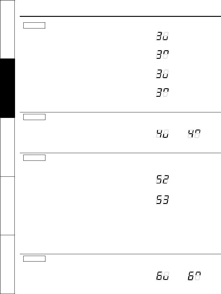
MODE 1 Smart Fan—Cooling/Heating
The default setting for Mode 1 is as follows: Cooling: Continuous (ON)
Heating: Cycle (OFF)
Press MODE until a 1 appears in the first digit of the display for Smart Fan cool mode. The COOL LED light on the main control will be on. To change to heat mode, press MODE again. The HEAT LED light on the main control will be lit. Press the down arrow to set the indoor fan to cycle on/off when the unit is heating or cooling " 
 ." Press the up arrow to set the indoor fan to run continuously "
  ." This is shown in the second digit of the display. Press AUX SET to confirm your selection and exit AUX SET mode, or press MODE to continue setting other functions.
*Note: In cyclic cooling mode, the indoor fan will activate occasionally to verify airtemperature in the room. In cyclic heating mode, the fan will continue to operate for 90seconds after the heating function has stopped in order to increase unit efficiency.
|
|
HIGH |
|
COOL |
|
|
|
||
|
|
|||
|
|
|
||
|
|
LOW |
|
FAN |
|
|
|
||
|
|
AUTO |
|
HEAT |
|
|
|
||
Cooling – Cycle* |
|
|
||
|
|
HIGH |
|
COOL |
|
|
|
||
|
|
LOW |
|
FAN |
|
|
|
||
|
|
AUTO |
|
HEAT |
|
|
|
||
Cooling – Continuous |
|
|
||
|
|
HIGH |
|
COOL |
|
|
|
||
|
|
LOW |
|
FAN |
|
|
|
||
|
|
AUTO |
|
HEAT |
|
|
|
||
Heating – Cycle* |
|
|
||
|
|
HIGH |
|
COOL |
|
|
|
||
|
|
LOW |
|
FAN |
|
|
|
||
|
|
AUTO |
|
HEAT |
|
|
|
||
Heating – Continuous |
|
|
||
MODE 2 Load Shedding (Central Desk Control)
The default setting for Mode 2 is OFF.
This feature is active only if the unit is connected to a CDC and the CDC has control. Press MODE until a 2 appears in the first digit of the display for Load Shedding mode. Press the down arrow for OFF " " or the up arrow for ON "
 ." This is shown in the second digit of the display. When this mode is on, only the indoor fan can be turned ON or OFF with the unit controls. When this mode is off, all operation is disabled except Heat/Freeze Sentinel (Mode 3). Press AUX SET to confirm your selection and exit AUX SET mode, or press MODE to continue setting other functions.
Load |
Load |
Shedding |
Shedding |
OFF |
ON |
5
Instructions Safety
Instructions Operating
Cleaning and Care
Tips Troubleshooting
Support Consumer
Safety Instructions
Operating Instructions
Care and Cleaning
Troubleshooting Tips
Consumer Support
Auxiliary controls on your Zoneline.
MODE 3 Freeze Sentinel/Heat Sentinel
In the default setting for Mode 3, Heat Sentinel is off, Freeze Sentinel is on.
Press MODE until a 3 appears in the first digit of the display for Freeze Sentinel mode. The COOL LED light on the main control will be on. Press MODE again to change to the Heat Sentinel. The HEAT LED light on the main control will be on. Press the down arrow for OFF " 
 " or the up arrow for ON "
 ." This is shown in the second digit of the display. Press AUX SET to confirm your selection and exit AUX SET mode, or press MODE to continue setting other functions.
When Freeze Sentinel is activated, it automatically provides heat without user interface. This helps to prevent plumbing damage by turning the heater and indoor fan ON at 41ºF and OFF at 46ºF.
When Heat Sentinel is activated, it automatically provides cooling without user interface. This helps to prevent an excessively hot room by turning the air conditioner ON at 85ºF and OFF at 80ºF.
NOTE: These functions are active whenever the unit is plugged in, even if the unit is in the STOP position.
|
|
HIGH |
|
COOL |
|
|
|
||
|
|
|||
|
|
|
||
|
|
LOW |
|
FAN |
|
|
|
||
|
|
AUTO |
|
HEAT |
|
|
|
||
Freeze Sentinel OFF |
|
|
||
|
|
HIGH |
|
COOL |
|
|
|
||
|
|
LOW |
|
FAN |
|
|
|
||
|
|
AUTO |
|
HEAT |
|
|
|
||
Freeze Sentinel ON |
|
|
||
|
|
HIGH |
|
COOL |
|
|
|
||
|
|
LOW |
|
FAN |
|
|
|
||
|
|
AUTO |
|
HEAT |
|
|
|
||
Heat Sentinel OFF |
|
|
||
|
|
HIGH |
|
COOL |
|
|
|
||
|
|
LOW |
|
FAN |
|
|
|
||
|
|
AUTO |
|
HEAT |
|
|
|
||
Heat Sentinel ON |
|
|
||
MODE 4 Constant ON Fan
The default setting for Mode 4 is OFF.
Press MODE until a 4 appears in the first digit of the display to set the fan to run continuously at high speed, even if the unit is in the STOP position. Press the down arrow for OFF " " or the up arrow for ON "
  ." This is shown in the second digit of the display. Press AUX SET to confirm your selection and exit AUX SET mode, or press MODE to continue setting other functions.
Constant |
Constant |
Fan OFF |
Fan ON |
MODE 5 Temperature Limiting
The default setting for Mode 5 is as follows: Cool: 2 (66ºF to 85ºF)
Heat: 5 (60ºF to 78ºF)
Press MODE until a 5 appears in the first digit of the display for Temperature Limiting cool mode. The COOL LED light on the main control will be lit. To change to heat mode, press MODE again and the HEAT LED light on the main control will be lit. To set the temperature limits, press the up or down arrow keys. The second digit of the display will be between 0 and 7 depending on the limit you want to set. The chart shows the limits available. Press AUX SET to confirm your selection and exit AUX SET mode, or press MODE to continue setting other functions.
Temperature limits—Cool |
Temperature limits—Heat |
0 = 60°F to 85°F |
0 = 60°F to 65°F |
1 = 64°F to 85°F |
1 = 60°F to 70°F |
2 = 66°F to 85°F |
2 = 60°F to 72°F |
3 = 68°F to 85°F |
3 = 60°F to 74°F |
4 = 70°F to 85°F |
4 = 60°F to 76°F |
5 = 72°F to 85°F |
5 = 60°F to 78°F |
6 = 74°F to 85°F |
6 = 60°F to 80°F |
7 = 76°F to 85°F |
7 = 60°F to 85°F |
|
|
HIGH |
|
COOL |
|
|
|
||
|
|
|||
|
|
|
||
|
|
LOW |
|
FAN |
|
|
|
||
|
|
AUTO |
|
HEAT |
|
|
|
||
Temperature Limiting Cool – Limit 2 |
||||
|
|
HIGH |
|
COOL |
|
|
|
||
|
|
LOW |
|
FAN |
|
|
|
||
|
|
AUTO |
|
HEAT |
|
|
|
||
Temperature Limiting Heat – Limit 3
MODE 6 Remote Thermostat – Class 2
|
The default setting for Mode 6 is OFF. |
|
|
||||
|
Setting this mode to ON will allow the unit to operate with a Class |
|
|
||||
|
2 Remote Control Wall Thermostat. Press MODE until a 6 appears |
|
|
||||
|
in the first digit of the display for Class 2 mode. Press the down |
|
|
||||
|
arrow to turn the option OFF " |
|
." Press the up arrow to turn this |
Class 2 OFF |
Class 2 ON |
||
|
|
||||||
|
|
||||||
|
option ON " |
|
." This is shown in the second digit of the display. |
||||
|
|
||||||
|
|
||||||
6 |
Press AUX SET to confirm your selection and exit AUX SET mode, |
|
|
||||
or press MODE to continue setting other functions. |
|
|
|||||
|
|
|
|||||
GEAppliances.com
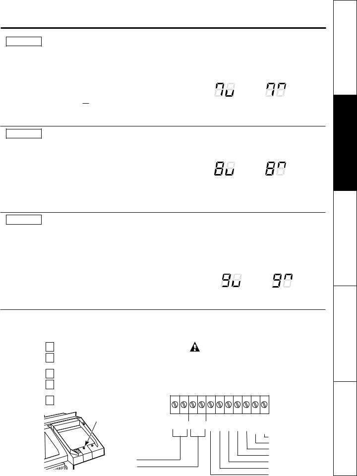
MODE 7 Duct Mode
The default setting for Mode 7 is OFF.
This setting is used when the unit is installed using a duct adapter kit. If the unit is ducted, the Duct Mode needs to be set to ON. This increases the fan speed to ensure proper circulation.
Press MODE until a 7 appears in the first digit of the display. Press the up or down arrow keys to set this switch to OFF " 
 " or ON "
  ." This is shown in the second digit of the display. Press AUX SET to confirm your selection and exit AUX SET mode.
For Model AZ6100, press MODE to continue setting other functions. Pressing MODE on Model AZ4100 will return you to AUX SET mode and an “AU” will appear in the display.
Duct Mode OFF |
Duct Mode ON |
MODE 8 All-Electric Heat (AZ6100 only)
The default setting for Mode 8 is OFF.
This electric heat option functions only on the 6100 model. When this option is ON "  ," heat pump operation is locked out, causing the unit to provide only electric resistance heat.
To set All-Electric Heat option, press MODE until an 8 appears in the first digit of the display. Press the up or down arrow keys to set this switch to OFF " 
 " or
" or
ON "  ." This is shown in the second digit of the display.
Press AUX SET to confirm your selection and exit AUX SET mode, or press MODE to continue setting other functions.
All-Electric |
All-Electric |
Heat OFF |
Heat ON |
MODE 9 Heat Boost (AZ6100 only)
The default setting for Mode 9 is OFF.
When Heat Boost is ON and outer temperatures are between 25ºF and 46ºF, heat pump only operation is locked out. This setting is used to provide supplementary heat to the heat pump operation by electric resistance heat in conditions where the heat pump-only operation is not sufficient to maintain a consistent, comfortable room temperature. NOTE: Temperature Boost option should not be used with remote thermostat operation. This will cause the unit to switch to resistance heat when the outdoor temperature is 46ºF.
To set Heat Boost, press MODE until a 9 appears in the first digit of the display. Press the up or down arrow keys to set this switch to OFF "  " or ON "
  ." This is shown in the second digit of the display. Press AUX SET to confirm your selection and exit AUX SET mode.
Heat Boost OFF |
Heat Boost ON |
Auxiliary Controls—Terminal Connections
The auxiliary controls are located behind the room |
|
|
The owner is responsible for making all connections and |
|||||||||
cabinet beneath the access cover. |
|
|
setting the appropriate AUX SET mode. |
|
||||||||
1 Turn off and unplug the unit. |
|
|
|
CAUTION: |
|
|
|
|||||
|
Remove the room cabinet. See the to Remove the |
|
|
Improper wiring may damage the Zoneline electronics. |
|
|||||||
2 Room Cabinet section. |
|
|
|
|||||||||
|
|
No common busing is permitted. Damage or erratic |
|
|||||||||
3 |
|
|
|
|
||||||||
Remove the screw from the access cover. |
|
|
operation may result. A separate wire pair must be run |
|
||||||||
To make wiring connections, insert the wires into the |
|
from each separate controlling switch to each individual |
||||||||||
|
|
Zoneline. |
|
|
|
|
|
|
|
|||
4 bottom of the terminals and tighten screws securely. |
|
|
|
|
|
|
|
|
||||
|
|
|
|
|
|
|
|
|
|
|||
|
After all desired connections have been made, |
|
|
|
|
|
|
|
|
|
|
|
5 replace the access cover and room cabinet. |
|
|
|
|
|
|
VALREVB |
|
HEATAUXW |
COMMONC |
|
|
|
Access Cover |
EXT |
FAN |
CDC |
VAC24 R |
FANLO G |
FANHI G |
COMPY |
|
|||
|
|
|
|
|
|
|
|
|
|
|
|
|
|
|
|
|
|
|
|
|
|
|
|
Common |
|
|
|
|
|
|
|
|
|
|
|
|
White - Heater |
|
|
|
|
|
|
|
|
|
|
|
|
Yellow - Compressor |
|
|
External Fan |
|
|
|
|
|
|
|
|
|
Black - Solenoid (AZ61 only) |
|
|
|
|
|
|
|
|
|
|
|
Green - High Speed Fan |
|
|
|
Desk Control |
|
|
|
|
|
|
|
|
|
|
|
|
|
|
|
|
|
|
|
|
|
Green - Low Speed Fan |
7 |
|
|
|
|
|
|
|
|
|
|
|
|
||
|
|
|
|
|
|
|
|
|
|
|
Red - 24 V AC only |
|
Instructions Safety
Instructions Operating
Cleaning and Care
Tips Troubleshooting
Support Consumer

Safety Instructions
Operating Instructions
Care and Cleaning
Troubleshooting Tips
Consumer Support
Auxiliary controls on your Zoneline.
External Fan (Obtained locally)
When connected, an auxiliary or external fan can be controlled with the indoor fan motor on the Zoneline. Connections provide 24 V AC to energize a remote relay, turning on the external fan.
Central Desk Control
When connected, the unit can be turned ON or OFF with a switch located at the Central Control Panel. A separate wire pair must be run from each separate controlling switch to each individual Zoneline.
Refer to MODE 2 on page 5 for fan setting options.
Remote Thermostat
When connected to a remote thermostat, the indoor air temperature sensing is shifted from the unit to the remote thermostat. For this reason, the units will operate slightly differently when connected to a remote thermostat. The following chart shows the unit operation when connected to a remote thermostat.
NOTE: The Class 2 Mode setting (Mode 6) must be set to ON "  " for the unit to operate with a Class 2 Remote Wall Thermostat. (See the installation instructions supplied with the remote thermostat and Mode instructions on page 7.)
Class 2 Shown ON
IMPORTANT: The Zoneline thermostat connections provide 24 V AC only.
If using a digital/electronic wall thermostat, you must set it to the 24 V AC setting. See the Installation Instructions for the wall thermostat.
 CAUTION:
Damage to a wall thermostat or to the Zoneline electronics can result from improper connections. Special care must be used in connecting the wires. No line voltage connections should be made to any circuit. Isolate all wires in building from line voltage.
|
Feature |
Heat Pump |
Electric Heat |
|
Indoor Frost Control |
Yes |
Yes |
|
Freeze Sentinel |
Yes |
Yes |
|
Auto Fan Speed |
No |
No |
|
Electronic Temperature Limiting |
No |
No |
|
Switch to Resistance Heat Based |
Determined by |
N/A |
|
On Indoor Temperature |
Remote Thermostat |
|
|
Switch to Resistance Heat Based |
Yes |
N/A |
|
On Outdoor Temperature |
|
|
|
Reverse Cycle Defrost |
Yes |
N/A |
|
Simultaneous Resistance Heat |
No |
N/A |
|
with Heat Pump |
|
|
|
Resistance Heat Lockout |
Yes |
N/A |
|
“Smart Fan” Fan Cycle |
Fan ON/AUTO Set On |
Fan ON/AUTO Set On |
|
|
Remote Thermostat |
Remote Thermostat |
8 |
Central Desk Control |
Yes |
Yes |
|
|||
|
|
|
|
 Loading...