


AZ38H09EADM2
GE AZ38H09EADM2, AZ38H09EACM2, AZ38H09EABM2, AZ38H09DADM2, AZ38H09DACM2 Owner’s Manual
...
www.GEAppfiances.com
@
@
0
Sa]bty Instructions. .......... '2
Operating h_iructions
Aft Di _ectkm ................ 4
AuxiliaIw C(mtIols .......... 5-9
Con tIols .................... 3
To Remove the Room Cabi_et . .4
Ve_t C(mtrol ................ 4
Care and Cleaning
Air Filters .................. t 1
Base Pan .................. 1()
Outdo(n Coils .............. t0
Room Cabh_et a_d Case ...... 10
Ve_t Filter . ................ t0
Installation Instructions
Electrical Supply ......... t4-17
InstalliI_g the Zoneli_e .... 18, 19
Optional Drain Kit .......... 20
Preparation ................ 12
Replacii_g ai_ E×isti_g Ui_it? . . .t3
Troubleshooting Tips .... 21, 22
Noimal Operath_g Som_ds .... 23
Consumer Support
Consumer Support . . .Back Co_er
Product RegistratioI_ ...... 25, 26
XA_na_ tv . ................. 27
Heat/Cool Model 2800
Heat Pum]a Model 3800
Espa_ol
For a Spanish version of this
manual, visit our _Yebsite at
w_vw.GEAppliances.com.
Para consultar una version ell
espafio] de este manual de
instrucciones, visite nuestro
sitio de internet
w_a,w.GEAppliances.com.
Fran_aise
For a French version of this
manual, visit our VCebsite at
w_a,w.GEAppliances.com.
Pour une version flanqaise de
ce manuel d'utilisation, veuillez
visiter notre site web fi ]'adresse
w,a,w.GEAppliances.com.
Write the model and serial
numbers here:
Model #
Serial #
Find these numbers on a label
behind the room cabinet on the
base pan.
TINSEA361JBRZ 49-7511
07-05JR
IMPORTANTSAFETYINFORMATION.
READALLINSTRUCTIONSBEFOREUSING.
WARNING!
Foryour safe_ the information in this manual must be followed to minimize the risk of fire or
explosion, electric shock, or to prevent property damage, personal injury, or loss of life.
SAFETYPRECAUTIONS
This Zoneline must be properly
installed in accordance with the
Installation Instructions before it is
used. See the Installation Instructions
in the back of this manual.
Replacing an existing unit?
For details, see the Installation
Instructions in this manual.
• Immediately repair or replace all
electric service cords that have become
flaved or otherwise damaged.
• Unplug or disconnect the Zoneline at
the fllse box or circuit breaker before
making any repairs.
NOTE;¼:e strongly recommend that any
servicing be performed by a qualified
individual.
READANDFOLLOWTHISSAFETYINFORMATIONCAREFULLY.
SAVETHESEINSTRUCTIONS
2

Aboutthe controlsonyourZoneline. .CEA..lia.ces.com
?
TEMPCONTROL
0
MODECONTROL
@
Co trols
TempControl
The temp control is used to maintain the
I'00111 tell/pei'att/i'e. The COlll[)i'essoi" will
c_cle on and off to kee I) the room at the
same comtort level. _,_]_en w)u tm'n the
knob to COOLER(blue), the indoor air
will become cooler. Tm'n the knob to
WARMER (red) and the indoor air will
becollle wa illlei i
3800Series only
_,_]_en the outdoor temperatm'e is lower
than 20°E heat is provided b)' the electric
heater in the air conditioner instead of bv
the heat I)ump.
Mode Control
HIGH COOLand LOW COOLpr_Mde cooling
with different tim speeds.
HIGHHEATand tOW HE4Tprovide heating
with different tim speeds.
LOWFAN or HIGH FAN provides air
circulation and filtering without cooling
or heating.
NOTE:If youmove the switch from acool orheat
setting to STOPorto a fan setting, the unit hasan
automatic3-minute delaybefore a//owlbg the
compressortorestart in thecool or heatmode.
About YourHeat Pump (3800 Series only)
Heat pmnps can save money by removing heat
fl'om the outside air----even when the outside
temperature is below freezing--and releasing
that heat indom_.
To get the best pet_kmnance flxm_ ):ore" heat
l)ump, don't change the room them_ostat ve_y
otten. Raising the heat setting 2-3 degrees will
cause the Zoneline to use its electric heating
elements in order to reach the new temperatm'e
setting quickly.
There is a three mimlte minimum compressor
run time at any setting to prevent short cycling.
The indoor tim motor sta_*s befl)re the
COllll)I'essoI" and stops aJ[teI" the coI/ll)I'essoI"
cycles off.
The electric heating elements use much
more electricit_ than heat l)mnps and cost
II/OI'e to ol)erate.
3

Otherfeaturesof yourZoneline.
Ventilation Control
The xentilation control lexer is located at the
upper lett side of the Zoneline unit, behind
the room cabinet.
_,_q_en set at the closed position, onE' the air
inside the room is circulated and filtered.
X,_]_en set at the open position, some outdoor
air will be drawn into the room. This will
reduce the heating or cooling efficiency.
Energy Tip: Kee I) the vent control at the closed
position. The room air will be filtered and
circulated.
NOTE:Twoshippingscrewsmustberemovedfromthe
ventdoorbeforeuse.Seethe/nstal/afionInstructions
in thebackofthismanual
Open
position
Vent
control Closed
(shownin position
middle
position)
ToRemovethe RoomCabinet
Additional controls are located 1)ehind the
I'OOIll cabinet.
To remove:Pull out at the bottom to release it
fl'om the tabs (l). Then lift up (_2).
To replace: Place the tabs oxer the top rail ( l ).
Push imvard at the bottom tmtil it snaps into
place (2).
Air Direction
To a(!just the air direction, remove the room
cabinet. Remove the 7 louver screws that hold
the louver insert in place. Flip the louver insert
180°, replace the screws and the room cabinet.
Louverscrews
Removethe room cabinet and flip the louver
insert to change the air direction.
Louverscrews
4
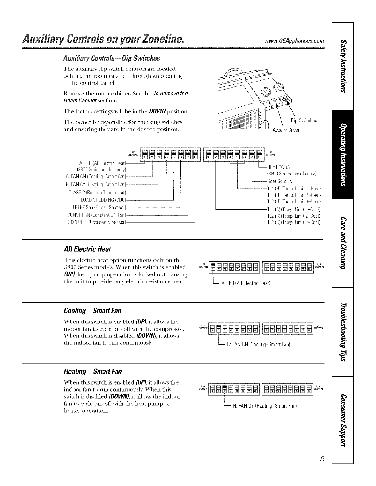
AuxiliarFContrMs--DipSwitches
The au_liary dip switch controls are located
behind the room cabinet, through an opening
in the control panel.
Remove the room cabinet. See the ToRemovethe
RoomCabinetsection.
The ti_cto_) settings will be in the DOWNposition.
The owner is responsible tor checking switches
and ensuring the) are in the desired position.
DipSwitches
AccessCover
ALLFR(All Electric Heat)--
(3800Series models only}
C: FAN CN(Coo%g-Smart Fan}
H: FAN CY(Heating-Smart Fan)
CLASS2 (RemoteThermostat)
LOADSHEDDING(CDQ
FREEZSen (FreezeSentinel}
CONSTFAN(Constant ON Fan)
OCCUPIED(OccupancySensor)
uP
DUwPN
HEATBOOST
(3%0 Series modelsonly}
Heat Sentinel
TL1(H)(Temp.Limit 1-Heat)
TL2(kl)(Temp.Limit 2-kleat)
TL3(HI (Temp.Limit 3-Heat)
TL1CO)(Temp.Limit I-Cool)
TL2(C)(Temp,Limit 2-Cool/
TL3(C/(Temp,Limit 3-Cool/
All Electric Heat
This electric heat option flmcfions only on the
3800 Series models. _._en this switch is enabled
(UP), heat pump operation is locked out, causing
the unit to provide only electric resistance heat.
° "L, BBBBBBBI[BBBBBBBBI° "
L ALLFR (All Electric Heat)
Cooling--Smart Fan
_,_l_en this switch is enabled (UP), it allows the
indoor tim to cycle on/offwith the compressor:
\,_l/en this switch is disabled (DOWN),it allows
the indoor Jilil [0 I'Un contintlo/ISlV.
o qa BBaBBaJjaaBBaaBa]o ,,
L C: FAN CN (Cooling-Smart Fan)
Heating--Smart Fan
When dds swkch is enabled (UP), k allo_s d_e
indoor tim to run continuousl): When this
switch is disabled (DOWN), it allows the indoor
tim to cycle on/off with the heat pump or
heater opei';ition.
BBBBBBBB]
OH: FAN CY (Heating-SmartFan)
AuMtiary contrMs on your Zone#he.
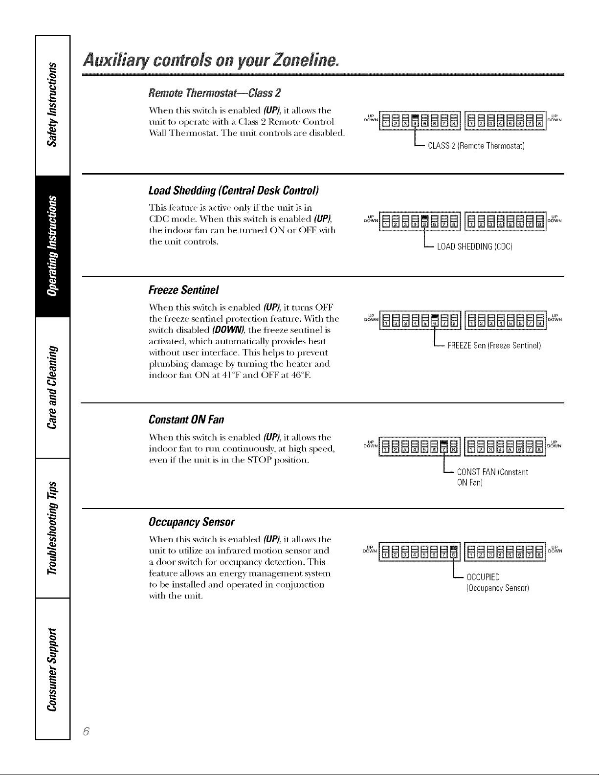
Remote Thermostat--Class 2
_._q_en this switch is enabled (liP), it allows the
unit to operate with a Class 2 Remote Control
Wall Them_ostat. The unit controls are disabled.
°"qBBB@BBBBBBBBBBBB1°"_"
L CLASS2 (Remote Thermostat)
LoadShedding(CentralDesk Control)
This feattu'e is active only if the unit is in
CDC mode. When this switch is enabled (UP),
the indoor tim can be turned ON or OFF with
the unit controls.
°"_°BBBB@BBBBBBBBBBB°"_°
L LOAD SHEDDING(CDC)
Freeze Sentinel
_._l_en this switch is enabled (UP), it turns OFF
the fl'eeze sentinel protection ieature. With the
switch disabled (DOWN),the fl'eeze sentinel is
acti\_ted, which automatically provides heat
without user inte_ti_ce. This helps to prevent
plumbing damage by turning the heater and
indoor tim ON at 41°F and OFF at 46°E
°_°IBBBBB@BBIBBBBBBBB °_°
L FREEZESen(FreezeSentinel)
Constant ON Fan
_q_en this switch is enabled (UP), it allows the
indoor tim to run continuously at high speed,
exen if the unit is in the STOP position.
L CONSTFAN(Constant
ONFan)
OccupancySensor
xAl_en this switch is enabled (UP),it allows the
unit to utilize an infl'ared motion sensor and
a door switch tot occupancy detection. This
tbature allo_vs an energy nmnagelnent system
to be installed and ope_wted in coqiunction
with the tmit,
"_BBBBBBBB
OCCUPIED
(OccupancySensor)
ww'w.GEApp#ences.com
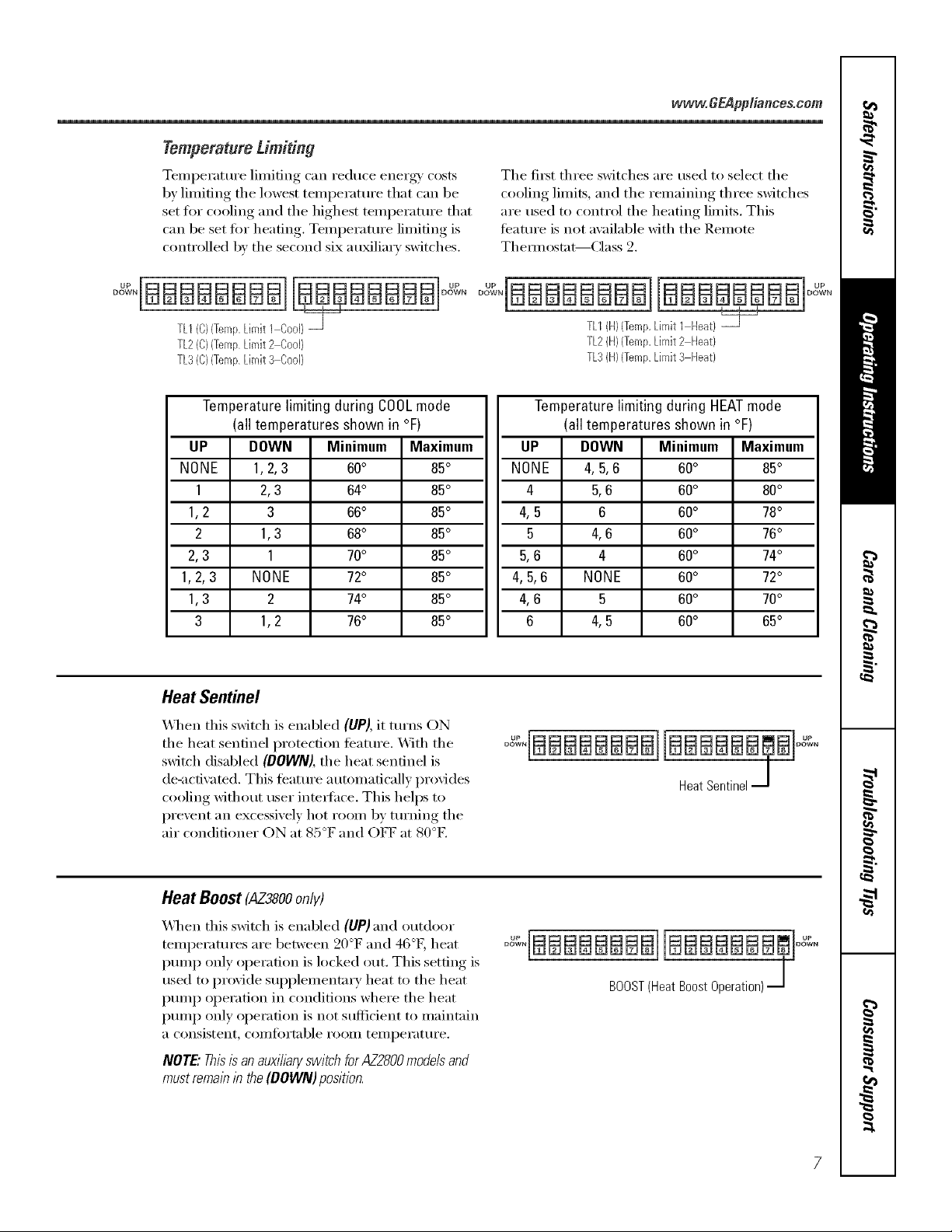
Temperature Limiting
TemI)erature limiting can reduce energy/costs
by limiting the lowest temperatm'e that can be
set for cooling and the highest temperatm'e that
can be set fi)r heating. Temperature limiting is
controlled by the second six auMliarv switches.
The fit_t three switches are used to select the
cooling limits, and the remaining three switches
are used to control the heating limits. This
teatm'e is not available with the Remote
Them_ost;_t--Class 2.
TL2(C)(TempLimit2 CooJ)
TL3(C}(TempLimit 3 Cool}
TLI{H){Temp,LimitI [-[eat)
TL2{H}{Temp,Limit2 [-[eat)
TL3(H)(TempLimit3 Heat)
Temperature limiting during COOLmode
(all temperatures shown in °F)
UP DOWN Minimum Maximum
NONE 1,2,3 60° 85°
1 2,3 64° 85°
1,2 3 66° 85°
2 1,3 68° 85°
2,3 1 70° 85°
1,2,3 NONE 72° 85°
1,3 2 74° 85°
3 1,2 76° 85°
Temperature limiting during HEATmode
(all temperatures shown in °F)
UP DOWN Minimum Maximum
NONE 4, 5,6 60° 85°
4 5,6 60° 80°
4,5 6 60° 78°
5 4,6 60° 76°
5,6 4 60° 74°
4,5,6 NONE 60° 72°
4,6 5 60° 70°
6 4,5 60° 65°
Heat Sentinel
X&l_en this switch is enabled (UP), it turns ON
the heat sentinel protection ti_atm'e. _]th the
switch disabled (DOWN), the heat sentinel is
de-activated. This teatm'e automatically provides
cooling without user intedhce. This helps to
prevent an excessively hot room by turning the
air conditioner ON at 85°F and OFF at 80°E
o 'IBBBBBBBBBBm.BIo "
HeatSentinelJ
Heat Boost (AZ38OOonly)
When this switch is enabled (UP) and outdoor
temperatures are between 20°F and 46°[h heat
pmnp only operation is locked out. This setting is
used to provide sui)plementary heat to the heat
pmnp operation in conditions where the heat
pmnp only operation is not sufficient to maintain
a consistent_ coi//t()rtable i'ooiil [eii/l)ei'_lt/li'e.
NOTE."Thisis an auxiibry switch for AZ2800mode# and
mustremab b the (BOWN) position.
° :'IBBBBBBBBI[BBBBBBBm]o :"
BOOST(HeatBoostOperation)J
Auxiliary controlsonyourZoneline.
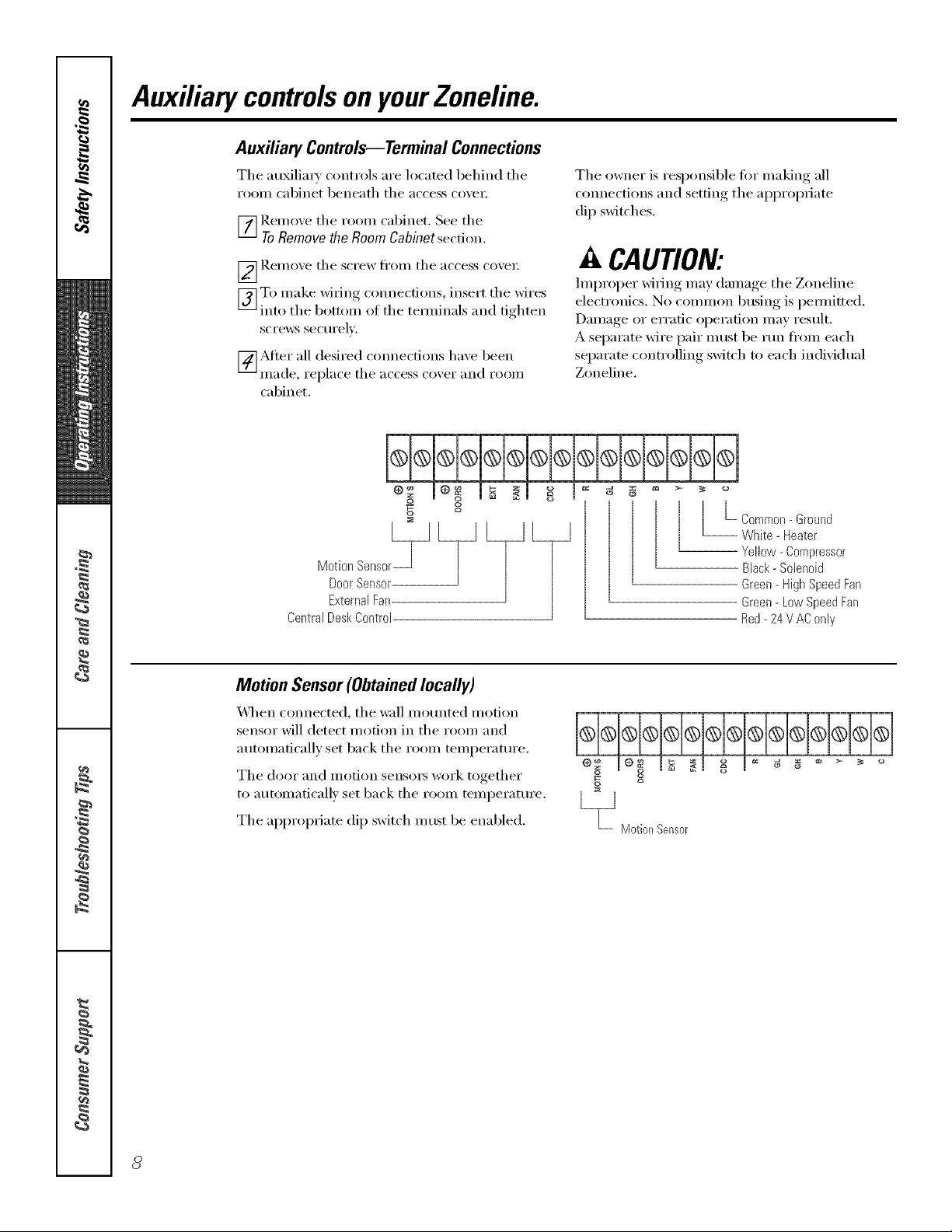
Auxiliaq Controls--Terminal Connections
Tile auMlia_ controls are located behind tile
rooiil cabinet beneath tile access coxei;
_] Remoxe tile room cabinet, See tile
ToRemovethe RoomCabinetsection.
_ Rei/loxe tile S(TeW tl'OIll tile }l('('ess ('o_ei;
[_]To make wi_ing c(mnecfions, inse_L tile wires
into tile bottom of tile tem_inals and tighten
screws sectlrelx,
[_Mter all desired connections have been
Illade, replace tile access coxer }lIl(l rooi/l
cabinet.
The owner is responsible fi)r making all
c(mnections and setting tile appropriate
dip switches.
A CAUTION:
Improper wi_ing may damage tile Zoneline
electronics. No common busing is pem_itted.
Damage or erratic operation may restflt.
A separate wire pair must be run fl'om each
separate controlling switch to each individual
Zoneline,
S
Door Sensor
External Fan
Central Desk Control
L Common- Ground
-- White - Heater
Yellow - Compressor
Black - Solenoid
Green- High Speed Fan
Green- Low Speed Fan
Red- 24 V AC only
Motion Sensor(Obtainedlocally)
_41/en c(mnected, tile wall mounted motion
sensor will detect motion in tile room and
automatically set back tile room temperattu'e.
The door and motion sensors work together
to automatically set back tile room temperature.
Tile appropriate dip switch m list be enabled.
L_ Motiel_Sensor
g I = g g
ca
www.GEAppliances.com
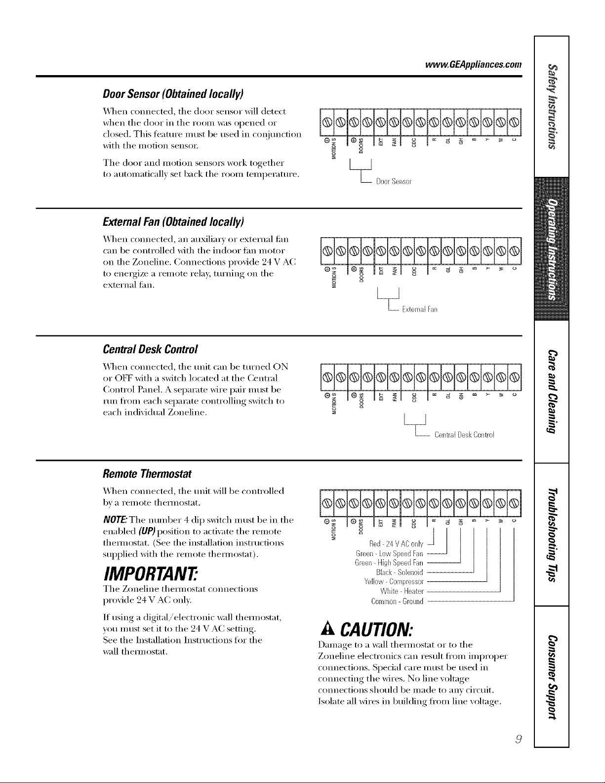
Door Sensor (Obtained locally)
_]/en connected, tile door sensor will detect
when tile door in tile i'OOill w;is opened or
closed. This teature nmst be used in coi_junction
with tile motion senso_:
Tile door and i/lotion sensoi3 work together
to automaticall_ set back tile room temperature.
%
S
m
L_ DoerSensor
External Fan(Obtainedlocally)
_4]/en connected, an auxiliary or external tim
can be controlled with tile indoor tim motor
on tile Zoneline. Com_ections provide 94 V AC
to energize a remora rela 5 turning on tile
external tim. g
[__1
"L ExternalFan
Central Desk Control
_&l/en com_ected, tile refit can be turned ON
or OFF with a switch located at tile Central
Control Panel. A separate wire pair nlust be
rtm fl'om each separate controlling switch to
each individual Zoneline.
[__J
_- CentralDeskCol_troJ
Remote Thermostat
X_q/en connected, tile trait _fill be controlled
bv a i'eillote thermostat.
NOTE'The number 4 dip switch must be in tile
enabled (UP) position to activate tile remote
themlostat, (See the installation instructions
supplied with tile remote themlostat).
IMPORTANT:
Tile Zoneline them/ostat connections
provide 24 V AC only.
If using a digital/electronic wall themlostat,
you must set it to tile 24 V AC setting.
See tile Installation Instructions fin" tile
wall them/ostat.
J
Red- 24 V AConly
Green-Low SpeedFan --
Green HighSpeedFan--
Black- Sobnoid
Yellow Compressor
White- bleater
Common-Ground
A CAUTION:
Damage to a wall themlostat or m tile
Zoneline electronics can result fl'om improper
com_ections. Special care nlust be used in
cmmecting the wires. No line voltage
connections should be made to anv circuit.
Isolate all wires in building ti'om line voltage.
 Loading...