


GE AZ61H09EAB, AZ41E09DAB, AZ41E09DAP, AZ41E12DAB, AZ61H15DAB Installation Guide
...<![endif]>Air Conditioners
<![if ! IE]><![endif]>Zoneline®
GEAppliances.com
Safety Instructions . . . . . . . . . . . . .2
Operating Instructions
Air Direction . . . . . . . . . . . . . . . . . . . . . . .4
Auxiliary Controls . . . . . . . . . . . . . . . .5–8
Controls . . . . . . . . . . . . . . . . . . . . . . . . . . .3
To Remove the Room Cabinet . . . . . .4
Ventilation Control . . . . . . . . . . . . . . . . .4
Care and Cleaning
Air Filters . . . . . . . . . . . . . . . . . . . . . . . . .10
Base Pan . . . . . . . . . . . . . . . . . . . . . . . . . .9
Outdoor Coils . . . . . . . . . . . . . . . . . . . . . .9
Room Cabinet and Case . . . . . . . . . . . .9
Ventilation Filter . . . . . . . . . . . . . . . . . . . .9
Installation Instructions
Electrical Connection . . . . . . . . . .13–16
Installing the Zoneline . . . . . . . . .17, 18
Optional Drain Kit . . . . . . . . . . . . . . . . .19
Preparation . . . . . . . . . . . . . . . . . . . . . . .11
Replacing an Existing Unit? . . . . . . . .12
Troubleshooting Tips . . . . .20, 21
Normal Operating Sounds . . . . . . . . .22
Consumer Support
Consumer Support . . . . . . . .Back Cover
Warranty . . . . . . . . . . . . . . . . . . . . . . . . .23
Owner’s Manual and
Installation Instructions
Heat/Cool Model 4100
Heat Pump Model 6100
Español
For a Spanish version of this manual, visit our Website at www.zoneline.com/literature.
Para consultar una version en español de este manual
de instrucciones, visite nuestro sitio de internet www.zoneline.com/literature.
Français
For a French version of this manual, visit our Website at www.zoneline.com/literature.
Pour un version français de
ce manuel d’utilisation, veuillez visiter notre site web à l’adresse www.zoneline.com/literature.
Write the model and serial numbers here:
Model # __________________
Serial # ____________________
Find these numbers on a label behind the room cabinet on the base pan.
TINSEA576JBRZ 49-7612-1 12-10 GE

<![endif]>Safety Instructions
<![if ! IE]><![endif]>Operating Instructions
<![if ! IE]><![endif]>Care and Cleaning
<![if ! IE]><![endif]>Troubleshooting Tips
<![if ! IE]><![endif]>Consumer Support
IMPORTANT SAFETY INFORMATION.
READ ALL INSTRUCTIONS BEFORE USING.
 WARNING!
for your safety, the information in this manual must be followed to minimize the risk of fire or explosion, electric shock, or to prevent property damage, personal injury, or loss of life.
safEty PRECautions
■This Zoneline must be properly installed in accordance with the Installation Instructions before it is used. See the Installation Instructions in the back
of this manual.
■Replace immediately all electric service cords that have become frayed or otherwise damaged. A damaged power supply cord must be replaced with a new power supply cord obtained from the manufacturer and not repaired.
Do not use a cord that shows cracks or abrasion damage along its length or at either the plug or connector end.
■Unplug or disconnect the Zoneline at the fuse box or circuit breaker before making any repairs.
NOTE: We strongly recommend that any servicing be performed by a qualified individual.
■These R410A air conditioning systems require contractors and technicians to use tools, equipment and safety standards approved for use with this refrigerant. DO NOT use equipment certified for R22 refrigerant only.
Replacing an existing unit?
For details, see the Installation Instructions in this manual.
REad and follow tHis safEty infoRMation CaREfully.


 SAVE THESE INSTRUCTIONS
2

About the controls on your Zoneline. |
GEAppliances.com |
|||
|
|
|
|
|
|
|
|
|
|
|
|
|
|
|
|
|
|
|
|
|
|
|
|
|
|
|
|
|
|
|
|
|
|
|
TEMP CONTROL FAN, MODE & SLEEP OPERATION
Controls
Temp Control
The temp control is used to maintain the room temperature. The compressor will cycle on and off to keep the room at the same level
of comfort.
Press the ▲ pad to raise the temperature. Press the ▼ pad to lower the temperature.
NOTE: The display shows the set temperature, not the room temperature.
Sleep
Press to set the air conditioner to run for 8 hours before it automatically returns to the previous setting.
When in the cooling mode and the sleep timer is set, the set temperature will automatically increase 2°F after the second hour then 1°F each hour over the next two hours. Also, the fan speed will change to low. When in the heating mode, the set temperature will decrease in the same manner.
To cancel the sleep mode, press the MODE pad or the SLEEP pad a second time.
Fan, Mode and Operation Control
FAN—Sets the fan operation for HIGH, LOW or AUTO speed. When set at AUTO, it automatically switches between LOW and HIGH as room temperature changes.
MODE—COOL—For cooling
FAN—For fan-only operation HEAT—For heating
OPERATION—ON/STOP—Turns the unit on or off. Power remains connected to the Zoneline. The Freeze/Heat Sentinel features still function if active.See the freezer/Heat sentinel section on page 6.
NOTE: the temperature display will flash to indicate a possible unit malfunction. set
operation control to STOP and then restart the unit. if the flashing light reappears within 30 minutes, call for service.
Quick Heat Recovery
Activates each time the thermostat is switched from STOP or COOL mode to HEAT mode. Electric heaters are energized until the thermostat set point
is reached. On heat pump models, the heat pump operation will resume at the next call for heat.
About Your Heat Pump (6100 Series only)
Heat pumps can save money by removing heat from the outside air—even when the outside temperature is below freezing—and releasing that heat indoors.
To get the best performance from your heat pump, don’t change the room thermostat very often. Raising the heat setting 2–3 degrees will cause the Zoneline to use its electric heating elements in
order to reach the new temperature setting quickly.
There is a 3-minute minimum compressor
run time at any setting to prevent short cycling.
The indoor fan motor starts before the compressor and stops after the compressor cycles off.
When the outdoor temperature is lower than 25°F, heat is provided by the electric heater in the air conditioner instead of by the heat pump.
The electric heating elements use much |
|
more electricity than heat pumps and cost |
3 |
more to operate. |
<![endif]>Instructions Safety
<![if ! IE]><![endif]>Instructions Operating
<![if ! IE]><![endif]>Cleaning and Care
<![if ! IE]><![endif]>Tips Troubleshooting
<![if ! IE]><![endif]>Support Consumer

<![endif]>Safety Instructions
<![if ! IE]><![endif]>Operating Instructions
<![if ! IE]><![endif]>Care and Cleaning
<![if ! IE]><![endif]>Troubleshooting Tips
<![if ! IE]><![endif]>Consumer Support
Other features of your Zoneline.
Ventilation Control |
Open |
Closed |
|
position |
|||
|
position |
||
NOTE: two shipping screws must be removed |
|
||
|
|
||
from the vent door before use. see the installation |
|
|
|
instructions in the back of this manual. if you do not |
|
|
|
plan to use the ventilation feature, leave these two |
|
|
|
screws in place. |
|
|
The ventilation control lever is located at the middle left side of the Zoneline unit, behind the room cabinet.
When set at the closed position, only the air inside the room is circulated and filtered.
When set at the open position, some outdoor |
Vent control |
|
|
air will be drawn into the room. This will reduce |
|
||
(shown in |
Remove two |
||
the heating or cooling efficiency. |
|||
middle position) |
|||
|
|
shipping screws |
|
Energy Tip: Keep the vent control in the closed |
|
(if operation is |
|
position. The room air will be filtered and circulated. |
|
desired) |
|
|
|
To Remove the Room Cabinet
Additional controls are located behind the room cabinet.
To remove: Pull out at the bottom to release it from |
To replace: Place the tabs over the top rail (1). Push |
the tabs (1). Then lift up (2). |
inward at the bottom until it snaps into place (2). |
Air Direction
To change the air direction, remove the room cabinet. Remove the 7 louver screws that hold the louver insert in place. Flip the louver insert 180°, replace the screws and the room cabinet.
Louver screws
4 |
Louver screws |
Remove the room cabinet and flip the louver insert to change the air direction.
Default position
Auxiliary controls on your Zoneline. |
GEAppliances.com |
|
|
Auxiliary Controls—Aux Set Button |
Auxiliary Set Button |
|
The auxiliary set controls are located behind the room cabinet, below the control panel.
Remove the room cabinet. See the to Remove the Room Cabinet section.
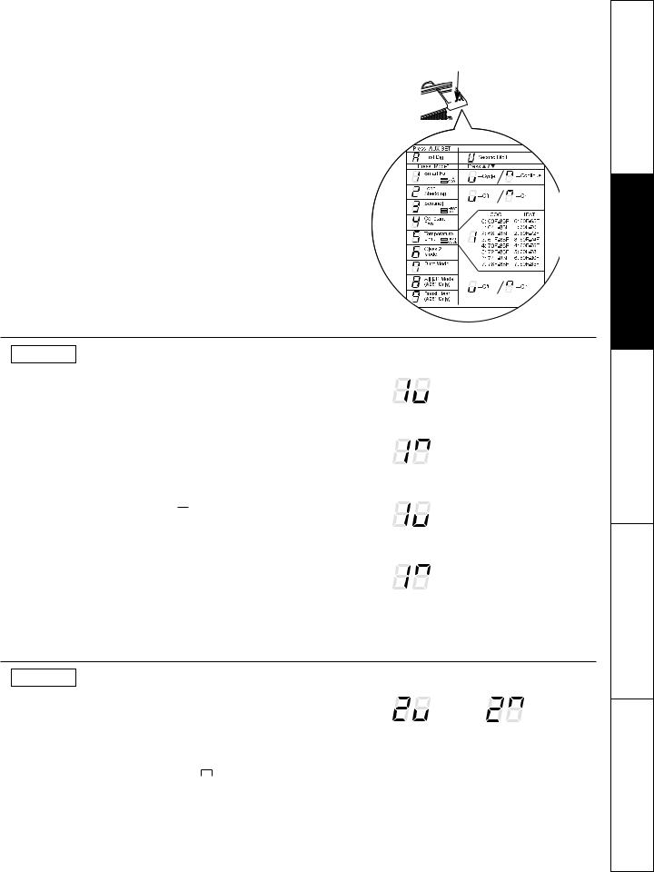
The owner is responsible for ensuring the auxiliary controls are set to the desired function. There are 9 different modes that can be set using the auxiliary set button. To change modes, press AUX SET (“AU” appears on the display). Press the mode button on the control pad until the first digit in the display shows the number corresponding to the mode you are choosing and the correct HEAT/COOL LED is lit. Press the up or down arrow (shown in the second digit of the display) to make the mode setting selection where applicable. Press the AUX SET button to confirm the selection.


 Access Cover
8 |
MODE 1 Smart Fan—Cooling/Heating
The default setting for Mode 1 is as follows: Cooling: Continuous (ON)
Heating: Cycle (OFF)
Press MODE until a 1 appears in the first digit of the display for Smart Fan cool mode. The COOL LED light on the main control will be on. To change to heat mode, press MODE again. The HEAT LED light on the main control will be lit. Press the down arrow to set the indoor fan to cycle on/off when the unit is heating or cooling " 
 ." Press the up arrow to set the indoor fan to run continuously "
  ." This is shown in the second digit of the display. Press AUX SET to confirm your selection and exit AUX SET mode, or press MODE to continue setting other functions.
*Note: In cyclic cooling mode, the indoor fan will activate occasionally to verify airtemperature in the room. In cyclic heating mode, the fan will continue to operate for 90seconds after the heating function has stopped in order to increase unit efficiency.
|
|
HIGH |
|
COOL |
|
|
|
||
|
|
|||
|
|
|
||
|
|
LOW |
|
FAN |
|
|
|
||
|
|
AUTO |
|
HEAT |
|
|
|
||
Cooling – Cycle* |
|
|
||
|
|
HIGH |
|
COOL |
|
|
|
||
|
|
LOW |
|
FAN |
|
|
|
||
|
|
AUTO |
|
HEAT |
|
|
|
||
Cooling – Continuous |
|
|
||
|
|
HIGH |
|
COOL |
|
|
|
||
|
|
LOW |
|
FAN |
|
|
|
||
|
|
AUTO |
|
HEAT |
|
|
|
||
Heating – Cycle* |
|
|
||
|
|
HIGH |
|
COOL |
|
|
|
||
|
|
LOW |
|
FAN |
|
|
|
||
|
|
AUTO |
|
HEAT |
|
|
|
||
Heating – Continuous |
|
|
||
MODE 2 Load Shedding (Central Desk Control)
The default setting for Mode 2 is OFF.
This feature is active only if the unit is connected to a CDC and the CDC has control. Press MODE until a 2 appears in the first digit of the display for Load Shedding mode. Press the down arrow for OFF "
" or the up arrow for ON " ." This is shown in the second digit of the display. When this mode is on, only the indoor fan can be turned ON or OFF with the unit controls. When this mode is off, all operation is disabled except Heat/Freeze Sentinel (Mode 3). Press AUX SET to confirm your selection and exit AUX SET mode, or press MODE to continue setting other functions.
Load |
Load |
Shedding |
Shedding |
OFF |
ON |
5
<![endif]>Instructions Safety
<![if ! IE]><![endif]>Instructions Operating
<![if ! IE]><![endif]>Cleaning and Care
<![if ! IE]><![endif]>Tips Troubleshooting
<![if ! IE]><![endif]>Support Consumer

<![endif]>Safety Instructions
<![if ! IE]><![endif]>Operating Instructions
<![if ! IE]><![endif]>Care and Cleaning
<![if ! IE]><![endif]>Troubleshooting Tips
<![if ! IE]><![endif]>Consumer Support
Auxiliary controls on your Zoneline.
MODE 3 Freeze Sentinel/Heat Sentinel
In the default setting for Mode 3, Heat Sentinel is off, Freeze Sentinel is on.
Press MODE until a 3 appears in the first digit of the display for Freeze Sentinel mode. The COOL LED light on the main control will be on. Press MODE again to change to the Heat Sentinel. The HEAT LED light on the main control will be on. Press the down arrow for OFF " 
 " or the up arrow for ON "
 ." This is shown in the second digit of the display. Press AUX SET to confirm your selection and exit AUX SET mode, or press MODE to continue setting other functions.
When Freeze Sentinel is activated, it automatically provides heat without user interface. This helps to prevent plumbing damage by turning the heater and indoor fan ON at 41ºF and OFF at 46ºF.
When Heat Sentinel is activated, it automatically provides cooling without user interface. This helps to prevent an excessively hot room by turning the air conditioner ON at 85ºF and OFF at 80ºF.
NOTE: These functions are active whenever the unit is plugged in, even if the unit is in the STOP position.
|
|
HIGH |
|
COOL |
|
|
|
||
|
|
|||
|
|
|
||
|
|
LOW |
|
FAN |
|
|
|
||
|
|
AUTO |
|
HEAT |
|
|
|
||
Freeze Sentinel OFF |
|
|
||
|
|
HIGH |
|
COOL |
|
|
|
||
|
|
LOW |
|
FAN |
|
|
|
||
|
|
AUTO |
|
HEAT |
|
|
|
||
Freeze Sentinel ON |
|
|
||
|
|
HIGH |
|
COOL |
|
|
|
||
|
|
LOW |
|
FAN |
|
|
|
||
|
|
AUTO |
|
HEAT |
|
|
|
||
Heat Sentinel OFF |
|
|
||
|
|
HIGH |
|
COOL |
|
|
|
||
|
|
LOW |
|
FAN |
|
|
|
||
|
|
AUTO |
|
HEAT |
|
|
|
||
Heat Sentinel ON |
|
|
||
MODE 4 Constant ON Fan
The default setting for Mode 4 is OFF.
Press MODE until a 4 appears in the first digit of the display to set the fan to run continuously at high speed, even if the unit is in the STOP position. Press the down arrow for OFF " " or the up arrow for ON "
  ." This is shown in the second digit of the display. Press AUX SET to confirm your selection and exit AUX SET mode, or press MODE to continue setting other functions.
Constant |
Constant |
Fan OFF |
Fan ON |
MODE 5 Temperature Limiting
The default setting for Mode 5 is as follows: Cool: 0 (60ºF to 85ºF)
Heat: 7 (60ºF to 85ºF)
Press MODE until a 5 appears in the first digit of the display for Temperature Limiting cool mode. The COOL LED light on the main control will be lit. To change to heat mode, press MODE again and the HEAT LED light on the main control will be lit. To set the temperature limits, press the up or down arrow keys. The second digit of the display will be between 0 and 7 depending on the limit you want to set. The chart shows the limits available. Press AUX SET to confirm your selection and exit AUX SET mode, or press MODE to continue setting other functions.
Temperature limits—Cool |
Temperature limits—Heat |
0 = 60°F to 85°F |
0 = 60°F to 65°F |
1 = 64°F to 85°F |
1 = 60°F to 70°F |
2 = 66°F to 85°F |
2 = 60°F to 72°F |
3 = 68°F to 85°F |
3 = 60°F to 74°F |
4 = 70°F to 85°F |
4 = 60°F to 76°F |
5 = 72°F to 85°F |
5 = 60°F to 78°F |
6 = 74°F to 85°F |
6 = 60°F to 80°F |
7 = 76°F to 85°F |
7 = 60°F to 85°F |
|
|
HIGH |
|
COOL |
|
|
|
||
|
|
|||
|
|
|
||
|
|
LOW |
|
FAN |
|
|
|
||
|
|
AUTO |
|
HEAT |
|
|
|
||
Temperature Limiting Cool – Limit 2 |
||||
|
|
HIGH |
|
COOL |
|
|
|
||
|
|
LOW |
|
FAN |
|
|
|
||
|
|
AUTO |
|
HEAT |
|
|
|
||
Temperature Limiting Heat – Limit 3
MODE 6 Remote Thermostat – Class 2
|
The default setting for Mode 6 is OFF. |
|
|
||||
|
Setting this mode to ON will allow the unit to operate with a Class |
|
|
||||
|
2 Remote Control Wall Thermostat. Press MODE until a 6 appears |
|
|
||||
|
in the first digit of the display for Class 2 mode. Press the down |
|
|
||||
|
arrow to turn the option OFF " |
|
." Press the up arrow to turn this |
Class 2 OFF |
Class 2 ON |
||
|
|
||||||
|
|
||||||
|
option ON " |
|
." This is shown in the second digit of the display. |
||||
|
|
||||||
|
|
||||||
6 |
Press AUX SET to confirm your selection and exit AUX SET mode, |
|
|
||||
or press MODE to continue setting other functions. |
|
|
|||||
|
|
|
|||||

GEAppliances.com
MODE 7 Duct Mode
The default setting for Mode 7 is OFF.
This setting is used when the unit is installed using a duct adapter kit. If the unit is ducted, the Duct Mode needs to be set to ON. This increases the fan speed to ensure proper circulation.
Press MODE until a 7 appears in the first digit of the display. Press the up or down arrow keys to set this switch to OFF " 
 " or ON "
  ." This is shown in the second digit of the display. Press AUX SET to confirm your selection and exit AUX SET mode.
For Model AZ6100, press MODE to continue setting other functions. Pressing MODE on Model AZ4100 will return you to AUX SET mode and an “AU” will appear in the display.
Duct Mode OFF |
Duct Mode ON |
MODE 8 All-Electric Heat (AZ6100 only)
The default setting for Mode 8 is OFF.
This electric heat option functions only on the 6100 model. When this option is ON "  ," heat pump operation is locked out, causing the unit to provide only electric resistance heat.
To set All-Electric Heat option, press MODE until an 8 appears in the first digit of the display. Press the up or down arrow keys to set this switch to OFF " 
 " or
" or
ON "  ." This is shown in the second digit of the display.
Press AUX SET to confirm your selection and exit AUX SET mode, or press MODE to continue setting other functions.
All-Electric |
All-Electric |
Heat OFF |
Heat ON |
MODE 9 Heat Boost (AZ6100 only)
The default setting for Mode 9 is OFF.
When Heat Boost is ON and outer temperatures are between 25ºF and 46ºF, heat pump only operation is locked out. This setting is used to provide supplementary heat to the heat pump operation by electric resistance heat in conditions where the heat pump-only operation is not sufficient to maintain a consistent, comfortable room temperature. NOTE: Temperature Boost option should not be used with remote thermostat operation. This will cause the unit to switch to resistance heat when the outdoor temperature is 46ºF.
To set Heat Boost, press MODE until a 9 appears in the first digit of the display. Press the up or down arrow keys to set this switch to OFF "  " or ON "
  ." This is shown in the second digit of the display. Press AUX SET to confirm your selection and exit AUX SET mode.
Heat Boost OFF |
Heat Boost ON |
Auxiliary Controls—Terminal Connections
The auxiliary controls are located behind the room |
|
|
The owner is responsible for making all connections and |
|||||||||
cabinet beneath the access cover. |
|
|
setting the appropriate AUX SET mode. |
|
||||||||
1 Turn off and unplug the unit. |
|
|
|
CAUTION: |
|
|
|
|||||
|
Remove the room cabinet. See the to Remove the |
|
|
Improper wiring may damage the Zoneline electronics. |
|
|||||||
2 Room Cabinet section. |
|
|
|
|||||||||
|
|
No common busing is permitted. Damage or erratic |
|
|||||||||
3 |
|
|
|
|
||||||||
Remove the screw from the access cover. |
|
|
operation may result. A separate wire pair must be run |
|
||||||||
To make wiring connections, insert the wires into the |
|
from each separate controlling switch to each individual |
||||||||||
|
|
Zoneline. |
|
|
|
|
|
|
|
|||
4 bottom of the terminals and tighten screws securely. |
|
|
|
|
|
|
|
|
||||
|
|
|
|
|
|
|
|
|
|
|||
|
After all desired connections have been made, |
|
|
|
|
|
|
|
|
|
|
|
5 replace the access cover and room cabinet. |
|
|
|
|
|
|
<![if ! IE]> <![endif]>VALREVB |
|
<![if ! IE]> <![endif]>HEATAUXW |
<![if ! IE]> <![endif]>COMMONC |
|
|
|
Access Cover |
<![if ! IE]> <![endif]>EXT |
<![if ! IE]> <![endif]>FAN |
<![if ! IE]> <![endif]>CDC |
<![if ! IE]> <![endif]>VAC24 R |
<![if ! IE]> <![endif]>FANLO G |
<![if ! IE]> <![endif]>FANHI G |
<![if ! IE]> <![endif]>COMPY |
|
|||
|
|
|
|
|
|
|
|
|
|
|
|
|
|
|
|
|
|
|
|
|
|
|
|
Common |
|
|
|
|
|
|
|
|
|
|
|
|
White - Heater |
|
|
|
|
|
|
|
|
|
|
|
|
Yellow - Compressor |
|
|
External Fan |
|
|
|
|
|
|
|
|
|
Black - Solenoid (AZ61 only) |
|
|
|
|
|
|
|
|
|
|
|
Green - High Speed Fan |
|
|
|
Desk Control |
|
|
|
|
|
|
|
|
|
|
|
|
|
|
|
|
|
|
|
|
|
Green - Low Speed Fan |
7 |
|
|
|
|
|
|
|
|
|
|
|
|
||
|
|
|
|
|
|
|
|
|
|
|
Red - 24 V AC only |
|
<![endif]>Instructions Safety
<![if ! IE]><![endif]>Instructions Operating
<![if ! IE]><![endif]>Cleaning and Care
<![if ! IE]><![endif]>Tips Troubleshooting
<![if ! IE]><![endif]>Support Consumer

<![endif]>Safety Instructions
<![if ! IE]><![endif]>Operating Instructions
<![if ! IE]><![endif]>Care and Cleaning
<![if ! IE]><![endif]>Troubleshooting Tips
<![if ! IE]><![endif]>Consumer Support
Auxiliary controls on your Zoneline.
External Fan (Obtained locally)
When connected, an auxiliary or external fan can be controlled with the indoor fan motor on the Zoneline. Connections provide 24 V AC to energize a remote relay, turning on the external fan.
Central Desk Control
When connected, the unit can be turned ON or OFF with a switch located at the Central Control Panel. A separate wire pair must be run from each separate controlling switch to each individual Zoneline.
Refer to MODE 2 on page 5 for fan setting options.
Remote Thermostat
When connected to a remote thermostat, the indoor air temperature sensing is shifted from the unit to the remote thermostat. For this reason, the units will operate slightly differently when connected to a remote thermostat. The following chart shows the unit operation when connected to a remote thermostat.
NOTE: The Class 2 Mode setting (Mode 6) must be set to ON "  " for the unit to operate with a Class 2 Remote Wall Thermostat. (See the installation instructions supplied with the remote thermostat and Mode instructions on page 7.)
Class 2 Shown ON
IMPORTANT: The Zoneline thermostat connections provide 24 V AC only.
If using a digital/electronic wall thermostat, you must set it to the 24 V AC setting. See the Installation Instructions for the wall thermostat.
 CAUTION:
Damage to a wall thermostat or to the Zoneline electronics can result from improper connections. Special care must be used in connecting the wires. No line voltage connections should be made to any circuit. Isolate all wires in building from line voltage.
|
Feature |
Heat Pump |
Electric Heat |
|
Indoor Frost Control |
Yes |
Yes |
|
Freeze Sentinel |
Yes |
Yes |
|
Auto Fan Speed |
No |
No |
|
Electronic Temperature Limiting |
No |
No |
|
Switch to Resistance Heat Based |
Determined by |
N/A |
|
On Indoor Temperature |
Remote Thermostat |
|
|
Switch to Resistance Heat Based |
Yes |
N/A |
|
On Outdoor Temperature |
|
|
|
Reverse Cycle Defrost |
Yes |
N/A |
|
Simultaneous Resistance Heat |
No |
N/A |
|
with Heat Pump |
|
|
|
Resistance Heat Lockout |
Yes |
N/A |
|
“Smart Fan” Fan Cycle |
Fan ON/AUTO Set On |
Fan ON/AUTO Set On |
|
|
Remote Thermostat |
Remote Thermostat |
8 |
Central Desk Control |
Yes |
Yes |
|
|||
|
|
|
|

Care and cleaning.
Room Cabinet and Case
Turn the Zoneline off and disconnect the |
To clean, use water and a mild detergent. |
power supply. |
Do not use bleach or abrasives. Some commercial |
|
cleaners may damage the plastic parts. |
Outdoor Coils
The coils on the outdoor side of the Zoneline should be checked regularly. If they are clogged with dirt or soot, they may be professionally steam cleaned. You will need to remove the unit from the wall sleeve to inspect the coils. The dirt buildup occurs on the fan side of the outdoor coil.
Coils
Grille
Clean the outside coils regularly.
Base Pan
In some installations, dirt or other debris may be |
In some areas of the United States, a naturally |
blown into the unit from the outside and settle in |
occurring “gel-like” or “slime-like” substance may be |
the base pan (the bottom of the unit). |
seen in the base pan. |
|
Check it periodically and clean, if necessary. |
Ventilation Filter
if the vent door is open, access requires the removal of the unit from the wall sleeve. Clean the vent filter twice a year or as required.
turn the Zoneline off and unplug before cleaning.
To clean the vent filter:
IMPORTANT:
This filter is not removable. Trying to remove this filter will damage the unit.
■Use a vacuum to remove debris from the filter.
■Use a damp rag to wipe down the filter and surrounding area after vacuuming.
Remove two shipping screws (if operation is desired)
9
<![endif]>Instructions Safety
<![if ! IE]><![endif]>Instructions Operating
<![if ! IE]><![endif]>Cleaning and Care
<![if ! IE]><![endif]>Tips Troubleshooting
<![if ! IE]><![endif]>Support Consumer

<![endif]>Safety Instructions
<![if ! IE]><![endif]>Operating Instructions
<![if ! IE]><![endif]>Care and Cleaning
<![if ! IE]><![endif]>Troubleshooting Tips
<![if ! IE]><![endif]>Consumer Support
Care and cleaning.
to maintain optimum performance, clean the filters at least every 30 days.
Air Filters
FRONT |
FRONT |
Dirty filter—Needs cleaning |
Clogged filter—Greatly |
|
reduces cooling, heating |
|
and airflow. |
Turn the Zoneline off before cleaning.
The most important thing you can do to maintain the Zoneline is to clean the filter at least every 30 days. Clogged filters reduce cooling, heating and air flow.
Keeping these filters clean will:
■Decrease cost of operation.
■Save energy.
■Prevent clogged heat exchanger coils.
■Reduce the risk of premature component failure.
To clean the air filters:
■Vacuum off the heavy soil.
■Run water through the filters from the back side.
■Dry thoroughly before replacing.
NOTE: The air filters are interchangeable and will fit in either the right or left side.
To remove the air filters:
2 Air filters
Pull up
To replace the air filters:
Push down
 CAUTION:Do not operate the Zoneline without the filters in place. If a filter becomes torn or damaged, it should be replaced immediately.
Operating without the filters in place or with damaged filters will allow dirt and dust to reach the indoor coil and reduce the cooling, heating, airflow and efficiency of the unit.
Replacement filters are available from your salesperson, GE dealer, GE Service and Parts Center or authorized Customer Care® servicers.
10
Installation |
Zoneline Air |
Instructions |
Conditioners |
|
|
Questions? Call 800.GE.CARES (800.432.2737) or Visit our Website at: GEAppliances.com
BEFORE YOu BEgIN
Read these instructions completely and carefully.
• IMPORTANT – Save these instructions for
local inspector’s use.
• IMPORTANT – Observe all governing codes and ordinances.
• Note to Installer – Be sure to leave these instructions with the owner.
• Note to Owner – Keep these instructions for future reference.
•Proper installation is the responsibility of the installer.
•Product failure due to improper installation is not covered under the Warranty.
TOOLS YOu WILL NEED
Phillips screwdriver
IMPORTANT ELECTRICAL
SAFETY—READ CAREFuLLY
 CAuTION:
•Follow the National Electrical Code (NEC) or local codes and ordinances.
•For personal safety, this Zoneline must be properly grounded.
•Protective devices (fuses or circuit breakers) acceptable for Zoneline installations are specified on the nameplate of each unit.
•Do not use an extension cord with this unit.
•Aluminum building wiring may present special problems—consult a qualified electrician.
•When the unit is in the OFF position, there is still voltage to the electrical controls.
•Disconnect the power to the unit before servicing by:
1 Removing the power cord (if it has one) from the wall receptacle.
OR
2Removing the branch circuit fuses or turning the circuit breakers off at the panel.
ZONELINE COMPONENTS
appearance may vary.
Zoneline unit
Room cabinet*
Power supply kit**
Exterior grille/louver** 
Wall case** 
** Shipped with the Zoneline unit
** Check the “Essential Elements” list on the unit located on front of the base pan
11

Installation Instructions
REPLACINg AN EXISTINg uNIT?
Check the “Essential Elements” label for important information.
use the correct wall case
This unit is designed to be installed in a GE plastic or insulated metal wall case. This minimizes condensation from forming on the room side of the case.
If the current wall case is not insulated, you can reduce the possibility of condensation forming by installing insulation kit RAK901L, available where you purchased the unit.
NOTE: There are several extra holes in the unit side flanges for installation in wall cases other than GE. To avoid damaging the flange insulation, the installer should use an awl or other sharp tool to puncture the insulation in the appropriate holes before installing the attachment screws.
use the correct outdoor grille
You should use the outdoor grilles shown on the “Essential Elements” label on the base pan.
•If an existing grille is not replaced, capacity and efficiency will be reduced and the unit may fail to operate properly or fail prematurely. A deflector kit, RAK40, may be used with grilles that were not designed for your new GE Zonelines. The RAK40 contains air deflectors and gaskets that mount to the unit to direct the hot exhaust air away from the air intake to allow the unit to function properly. The grille must have a 65% minimum free area.
•Any vertical deflectors in the existing rear grille should be removed to decrease condenser air recirculation that can cause the unit to “short-cycle” and lead to premature component failure.
use the correct power cord
Local codes may require the use of arc fault or leakage current detection devices on 230/208-volt installations.
Replacing a ducted unit
New ducted installation:
If this unit is to be installed in a new ducted application using a duct adapter kit, the kit must be installed before the unit is placed in the wall case. The installation instructions are packed with the kit.
Duct kits available:
RAK6052
RAK601/602
Mounting |
|
plate |
Duct |
|
Case |
Existing ducted installation:
Replacement of an existing ducted unit may require different components. Request this information from your sales representative.
•Replacing 230/208 volt units:
See page 13.
•Replacing 265 volt units:
See page 14.
When using a duct kit, you must always turn Mode 7 to ON "  ." See Mode instructions on page 7.
Duct Mode
Shown ON
12

Installation Instructions
230/208 VOLT ELECTRICAL CONNECTION OPTIONS
HOW TO CONNECT
1.Remove the room cabinet.
2.Connect to electrical power.
3.Review the following steps for applicable supply voltages.
4.Reinstall the room cabinet.
Power cords may include an arc fault interruption or a leakage current detection interruption device. A test and reset button is provided on the plug case or the inline case. The device should be tested on
a periodic basis by first pressing the TEST button and then the RESET button. If the TEST button does not trip or if the RESET button will not stay engaged, discontinue use of the Zoneline and contact a qualified service technician.
POWER CORD
CONNECTION
A power supply kit with LCDI must be used to supply power to the Zoneline unit. The appropriate kit is determined by the voltage, the means of electrical connection and
the amperage of the branch circuit.
appearance may vary.
Power supply kit
Connections of 208 or 230-volt circuits may be with a power supply kit or a junction box kit.
All wiring, including installation of the receptacle, must be in accordance with the NEC and local codes, ordinances and regulations. Codes require the use of an arc fault or leakage current detection device on the power cord except direct connect. Be sure to select the correct cord for your installation.
|
|
|
|
|
|
|
|
|
Tandem |
Perpendicular |
Large Tandem |
||||
|
15 Amp. |
20 Amp. |
|
30 Amp. |
|||
|
230/208-volt receptacle configuration. |
||||||
|
|
|
|
|
|
||
|
Branch Circuit and |
|
Proper GE Power Cord |
||||
Unit Amperage Rating |
|
|
with LCDI Device |
||||
|
|
|
|
|
|
|
|
|
|
15 |
|
|
RAK3153A |
||
|
|
|
|
|
|
|
|
|
|
20 |
|
|
RAK3203A |
||
|
|
|
|
|
|
|
|
|
|
30 |
|
|
RAK3303* |
||
|
|
|
|
|
|
|
|
*Not approved for use on 7000 BTU models.
ELECTRICAL SuBBASE
CONNECTION
230/208-volt models may be installed using one of the following electrical subbases:
Branch Circuit and |
Proper GE |
|
Unit Amperage Rating |
Subbase Kit |
|
|
|
|
15 |
RAK204D15P |
|
|
|
|
20 |
RAK204D20P |
|
|
|
|
30 |
RAK204D30P* |
|
|
|
|
*Not approved for use on 7000 BTU models.
Electrical subbases provide an enclosure for direct connection or enclosed receptacles. The subbase kit includes the power cord.
The instructions provided with the selected subbase kit must be carefully followed. It is the responsibility of the installer to ensure the connection of components is done in accordance with these instructions and all electrical codes.
DIRECT CONNECTION
Order the following Kit for 230/208-volt direct connection as required:
Branch Circuit and |
Power Supply |
Power |
|
Unit Amperage Rating |
Accessory |
Supply Kit |
|
|
|
|
|
15 |
RAK4002A |
RAK4157 |
|
|
|
|
|
20 |
RAK4002A |
RAK4207 |
|
|
|
|
|
30 |
RAK4002A |
RAK4307* |
|
|
|
|
|
*Not approved for use on 7000 BTU models.
Skip to the “MAKE ELECTRICAL CONNECTION TO THE UNIT” section.
13
Installation Instructions
265 VOLT ELECTRICAL CONNECTION OPTIONS
 WARNINg:
Connection of this 265 V AC product to a branch circuit MUST be done by direct connection in accordance with the National Electrical Code. Plugging this unit into a building-mounted exposed receptacle is not permitted by code.
These models must be installed using the appropriate GE power supply kit for the branch circuit amperage and the electrical resistance heater wattage desired. Use the POWER CONNECTION CHART on page 16 to determine the correct kit required. One of the following installation methods (A or B) must be used.
A. FOR SuBBASE INSTALLATION
Electrical subbase kits are available to provide a flexible enclosure for direct connection.
Branch Circuit and |
Proper GE |
Power |
Unit Amperage Rating |
Subbase Kit |
Supply Kit |
|
|
|
15 |
RAK204E15 |
RAK5172 |
|
|
|
20 |
RAK204E20 |
RAK5202 |
|
|
|
30 |
RAK204E30 |
RAK5302* |
|
|
|
*Not approved for use on 7000 BTU models.
The instructions provided with the selected subbase kit must be carefully followed. It is the responsibility of the installer to ensure the connection of components is done in accordance with these instructions and all electrical codes.
B. FOR DIRECT CONNECT INSTALLATION
If an electrical subbase is not used, direct connection to branch circuit wiring inside the provided junction box must be done in accordance with the following steps.
Order the following Kit for 265-volt direct connection as required:
Branch Circuit and |
Power |
|
Unit Amperage Rating |
Supply Kit |
|
|
|
|
15 |
RAK5157 |
|
|
|
|
20 |
RAK5207 |
|
|
|
|
30 |
RAK5307* |
|
|
|
|
*Not approved for use on 7000 BTU models.
Proceed to the “MAKE ELECTRICAL CONNECTION TO THE UNIT” section.
NOTE: Order Kit RAK4002CW to enable a quick disconnect inside the junction box.
14

Installation Instructions
MAKE ELECTRICAL CONNECTION TO THE uNIT
1REMOVE JuNCTION BOX
1.Remove the junction box cover by removing the front two screws.
2.Remove the junction box by removing the top and bottom rear screws. Note how the tabs on the lower left side of the junction box serve to hold the side in place. This will help when the box is being reinstalled.
Unit connector
Junction Junction box
box cover
2 CONNECT THE CORDSET
Plug the connector, provided in the Direct Connect Kit, fully into place in the unit mating connector. Be sure the locking tabs at the sides are engaged.
Connector
NOTE: Order Kit RAK4002CW to enable a quick disconnect inside the junction box.
3ATTACH CONDuIT
1.Use the round knockout at the bottom of the junction box to attach conduit coming from the branch circuit.
Remove the knockout, attach the conduit and bring wires into the junction box. Leave 6” of wire free at the end of the conduit to allow connections to be made.

 Conduit
2.If a fuse and fuseholder are to be used, the knockout at the top of the box is for mounting
a Buss fuseholder. Be sure the fuse and fuseholder are of the same rating as the branch circuit.
Leadwires at the fuse can be either soldered in place or attached using UL-listed 1/4” female (receptacle) crimp connectors. Follow local codes.
4REINSTALL JuNCTION BOX
•Reinstall the junction box by engaging the left tabs on the lower right face of the unit, aligning the screw holes at the top and bottom and driving the two screws until secure. Be sure that all wire leads are inside the box and not pinched between the box and
the unit. The green insulated ground wire from the unit MUST be connected to the branch circuit ground wire.
Make all wire connections by using appropriate UL-listed electrical connectors and techniques (black to black, white to white and green to green).
5REINSTALL JuNCTION BOX COVER
1.Carefully tuck all wires and connections back inside the junction box. Be sure there are no loose connections or stray uninsulated wires exposed.
2.Place the junction box cover in place. Replace the two screws removed earlier and tighten securely.
15

Installation Instructions
POWER CONNECTION CHART
Power Cord Connections
|
230/208 Volt |
|
|
|
|
|
|
|
Power Supply Kits |
|
|
|
|
|
|
|
with Current Leakage |
Wall Plug |
|
|
Heater Wattage |
||
|
Detection Device |
Configuration |
Circuit Protective Device |
@ 230/208 Volts |
|||
|
|
|
|
|
|
|
|
|
RAK3153A |
|
Tandem |
15-Amp Time-Delay Fuse or Breaker |
2.40/2.32 KW |
||
|
RAK3203A |
|
Perpendicular |
20-Amp Time-Delay Fuse or Breaker |
3.30/3.20 KW |
||
|
RAK3303* |
|
Large Tandem |
30-Amp Time-Delay Fuse or Breaker |
4.70/4.53 KW |
||
|
|
|
|
|
|
|
|
|
|
|
|
|
|
|
|
|
|
|
|
Direct Connections |
|
|
|
|
|
|
|
|
|
|
|
|
230/208 Volt |
|
|
|
Heater Wattage |
||
|
Power Supply Kits |
Circuit Protective Device |
@ 230/208 Volts |
||||
|
|
|
|
|
|
|
|
|
RAK4157 |
15-Amp Time-Delay Fuse or Breaker |
|
2.40/2.32 KW |
|||
|
RAK4207 |
20-Amp Time-Delay Fuse or Breaker |
|
3.30/3.20 KW |
|||
|
RAK4307* |
30-Amp Time-Delay Fuse or Breaker |
|
4.70/4.53 KW |
|||
|
|
|
|
|
|
|
|
|
265 Volt |
|
|
|
Heater Wattage |
||
|
Power Supply Kits |
Circuit Protective Device |
@ 265 Volts |
||||
|
|
|
|
|
|
|
|
|
RAK5157 |
15-Amp Time-Delay Fuse or Breaker |
|
2.40 KW |
|||
|
RAK5207 |
20-Amp Time-Delay Fuse or Breaker |
|
3.40 KW |
|||
|
RAK5307* |
30-Amp Time-Delay Fuse or Breaker |
|
4.80 KW |
|||
|
|
|
|
|
|
|
|
*Not approved for use on 7000 BTUH units.
16

Installation Instructions
INSTALLINg THE ZONELINE
1 INSTALL THE WALL CASE AND EXTERIOR gRILLE
The RAB71A series or RAB77A4 wall case must be properly installed per instructions packed with the case.
•Remove the corrugated stiffener and the outdoor protective panel. Use the slit in the outdoor panel as a handhold and push out.
Protective |
|
|
|
Slit |
|
|
|||
panel |
|
|
|
|
Stiffener
•Install the exterior grille from the room side following instructions packed with the grille.
Insulated Wall Case
This unit is designed to be installed in a GE plastic or an insulated steel wall case. This minimizes condensation from forming on the room side of the case.
The RAB71A series wall cases are insulated. Insulation kit RAK901L is available for use with RAB77A4 or existing uninsulated wall cases when needed.
NOTE: For installation with a subbase or duct adapter, see the instructions packed with those kits.
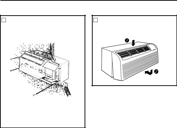
2PREPARE THE uNIT
•Carefully remove shipping tape and foam shipping blocks from the room cabinet, compressor and vent door. There may be multiple blocks and pieces of shipping tape that need to be removed.
Shipping tape 


 (Locations may vary)


•Remove the room cabinet by pulling it out at the bottom to release it (1); then lift it up to clear the rail along the unit top (2).
•If vent door is to be operational, remove shipping screws from the front side of the vent door, if present.
Remove two shipping screws (if operation is desired)
17
Installation Instructions
INSTALLINg THE ZONELINE (cont.)
3 INSTALL THE uNIT INTO THE WALL CASE
Slide the unit into the wall case and secure with four screws through the unit flange holes.
4 REPLACE THE ROOM CABINET
Reinstall the room cabinet by hooking the top over the rail along the unit top (1), then pushing it in at the bottom (2).
NOTE: There are several extra holes in the unit side flanges for installation in wall cases other than GE. To avoid damaging the flange insulation, the installer should use an awl or other sharp tool to puncture the
insulation in the appropriate holes before installing the attachment screws.
18

Installation Instructions
OPTIONAL—DRAIN KIT INSTALLATION
Dry Air 25 Series models are designed to improve dehumidification by 25%. Since more moisture will be removed from the air, there is a greater possibility that water will drip from the wall case than with a standard unit. To prevent this water from dripping onto external building walls, we recommend the use of RAD10 Drain Kit.
External Drain
See the Installation Instructions in the RAD10 kit.
Alternate:
6” long, 1/2” O.D. straight copper tube
1/2” O.D. drain tube
Square drain holes
Neoprene sponge gasket
Steel mounting plate


 Type “A” screw for metal case or
Type “B” screw for molded case
Internal Drain
See the Installation Instructions in the RAD10 kit.
(The drain is located under the cabinet)
Square drain holes |
Neoprene sponge gasket |
|
|
|
Steel mounting plate |


 Type “A” screw for metal case or
Type “B” screw for molded case
19
<![endif]>Safety Instructions
<![if ! IE]><![endif]>Operating Instructions
<![if ! IE]><![endif]>Care and Cleaning
<![if ! IE]><![endif]>Troubleshooting Tips
<![if ! IE]><![endif]>Consumer Support
Before you call for service…
troubleshooting tips
save time and money! Review the charts on the following pages first and you may not need to call for service.
Problem |
Possible Causes |
What To Do |
||
|
|
|
|
|
Zoneline does |
|
The unit is |
• Make sure the Zoneline plug is pushed completely |
|
not start |
|
unplugged. |
into the outlet. |
|
|
|
|
|
|
|
|
The power cord is not |
• Remove the room cabinet and make sure that the |
|
|
|
firmly attached. |
yellow connector on the end of the power cord is |
|
|
|
|
|
firmly engaged. |
|
|
|
|
|
|
|
The fuse is blown/circuit |
• Check the house fuse/circuit breaker box and replace |
|
|
|
breaker is tripped. |
the fuse or reset the breaker. |
|
|
|
|
|
|
|
|
The unit is waiting for |
• This is normal. The Zoneline will start again after |
|
|
|
the compressor overload |
it resets. |
|
|
|
protector to reset. |
|
|
|
|
|
|
|
|
|
Power failure. |
• If power failure occurs, set the mode control to STOP. |
|
|
|
|
|
When power is restored, set the mode control to the |
|
|
|
|
desired setting. |
|
|
|
|
• There is a protective time delay (up to 3 minutes) to |
|
|
|
|
prevent tripping of the compressor overload. For this |
|
|
|
|
reason, the unit may not start normal heating or cooling |
|
|
|
|
for 3 minutes after it is turned back on. |
|
|
|
|
|
|
|
The current interrupter |
• Press the RESET button located on the power cord plug |
|
|
|
device is tripped. |
or the box near the plug. |
|
|
|
|
|
• If the RESET button will not stay engaged, discontinue use |
|
|
|
|
of the Zoneline and contact a qualified service technician. |
|
|
|
|
|
Zoneline does not cool |
|
Indoor airflow |
• Make sure there are no curtains, blinds or furniture |
|
or heat as it should |
|
is restricted. |
blocking the front of the Zoneline. |
|
|
|
|
|
|
|
|
Outdoor airflow is |
• Make sure the rear grille is not restricted. This can |
|
|
|
restricted or recirculated. |
cause the unit to cycle off due to the compressor |
|
|
|
|
|
overload protector. |
|
|
|
|
• Outdoor grille must have a minimum of 65% free area. |
|
|
|
|
Non-GE grilles may be too restrictive for proper |
|
|
|
|
performance. Consult your salesperson for assistance. |
|
|
|
|
|
|
|
The temp control may |
• Turn the control to a lower or higher setting. |
|
|
|
not be set properly. |
NOTE: the temperature limiter may be limiting the |
|
|
|
|
|
temperature range. |
|
|
|
|
|
|
|
The air filter is dirty. |
• Clean the filter at least every 30 days. |
|
|
|
|
|
See the operating instructions section. |
|
|
|
|
|
|
|
The room may have |
• When the Zoneline is first turned on you need to |
|
|
|
been hot or cold. |
allow time for the room to cool down or warm up. |
|
|
|
|
|
|
|
|
Outdoor air is |
• Set the vent control to the closed position. |
|
|
|
entering the room. |
|
|
|
|
|
|
|
Burning odor at the start |
|
Dust is on the surface |
• This can cause a “burning” odor at the beginning of |
|
of heating operation |
|
of the heating element. |
the heating operation. This odor should quickly fade. |
|
|
|
|
|
|
20
|
|
|
GEAppliances.com |
|
|
|
|
|
|
|
|
Problem |
Possible Causes |
What To Do |
|
|
|
|
|
The air is not always |
The heat pump is not |
• This is normal. The heat pump will produce warm air |
|
cool or hot during |
producing hot air. |
but not as hot as air produced when the higher-cost |
|
operation |
|
|
electric heat is used. |
|
|
|
|
|
The Smart Fan Auxiliary |
• This causes the fan to blow room temperature air |
|
|
Controls may be set to |
even when the compressor or heater cycles off. |
|
|
continuous fan. |
The continuous air movement provides better |
|
|
|
|
overall temperature control in the cool mode. |
|
|
|
See smart fan – Cooling/Heating on page 5. |
|
|
|
|
The air does not feel |
The heat pump alone |
• Use the Electric Heat Option. This turns off the |
|
warm enough during |
produces air that feels |
heat pump and warms with electric heat only. |
|
heating operation |
cooler than desired. |
NOTE: use of this option will result in increased energy |
|
|
|
|
consumption. |
|
|
|
|
The unit is not |
The Smart Fan Auxiliary |
• See smart fan – Cooling/Heating on page 5. |
|
blowing out air |
Controls may be set to cycle. |
|
|
|
|
|
|
The electric heating |
The power cord is not |
• Remove the room cabinet and make sure that the |
|
feature does not work |
firmly attached. |
yellow connector on the end of the power cord is |
|
|
|
|
firmly engaged. |
|
|
|
|
Temperature display |
The compressor may |
• Set the operation control to STOP and then restart |
|
flashes |
have failed. |
the unit. If the flashing light reappears within |
|
|
|
|
30 minutes, call for service. |
|
|
|
|
21
<![endif]>Instructions Safety
<![if ! IE]><![endif]>Instructions Operating
<![if ! IE]><![endif]>Cleaning and Care
<![if ! IE]><![endif]>Tips Troubleshooting
<![if ! IE]><![endif]>Support Consumer

<![endif]>Safety Instructions
<![if ! IE]><![endif]>Operating Instructions
<![if ! IE]><![endif]>Care and Cleaning
<![if ! IE]><![endif]>Troubleshooting Tips
<![if ! IE]><![endif]>Consumer Support
Things that are normal.
Normal Operating Sounds
“CLICK”
|
|
|
|
te |
|
|
|
|
u |
||
|
|
n |
|
|
|
|
|
i |
|
|
y |
M |
|
|
|||
- |
|
a |
|||
3 |
|
|
l |
|
|
|
e |
|
|
||
|
D |
|
|
|
|
SILENCE
COMPRESSOR PROTECTION
You may hear a pinging noise caused by water being picked up and thrown against the condenser on rainy days or when the humidity is high. This design feature helps remove moisture and improve efficiency.
You may hear relays click when the controls cycle on and off or are adjusted to change the room temperature.
Water will collect in the base pan during high humidity or on rainy days. The water may overflow and drip from the outdoor side of the unit.
The indoor fan runs continuously when the unit is operating in the cooling mode, unless the Smart Fan Auxiliary Control is set to cycle. This will cause the fan to cycle on and off with the compressor. You may also hear a fan noise stop and start.
There are times when the fan on the unit will run even when the unit is not heating or cooling. If the system is set up to be in continuous fan the indoor fan will run regardless if the unit may be cooling or heating. Other times the fan will run longer than the heating/cooling cycle or kick on occasionally. This is normal and is done to improve room comfort and balance.
You may notice a few minutes delay in starting if you try to restart the Zoneline too soon after turning it off or if you adjust the thermostat right after the compressor has shut off. This is due to a built-in restart protector for the compressor that causes
a 3-minute delay.
During the defrost cycle, both indoor and outdoor fans stop and the compressor will operate in the cooling mode to remove frost from the outdoor coil. After defrost, the unit will restart in electric heat to quickly warm the room to the desired comfort level.
To protect the compressor and prevent short cycling, the unit is designed to run for a minimum of 3 minutes after the compressor starts at any thermostat setting.
22
 Loading...