


GE ARC13AHC, ARC13AAC, ARC15AAC, ARH13AHC, ARH15AAC Owner’s Manual
...<![endif]>RV AIR CONDITIONER
SAFETY INFORMATION . . . . . . . . .3
INSTALLATION INSTRUCTIONS
Before You Begin . . . . . . . . . . . . . . . . . . . . . .4 Tools You will Need . . . . . . . . . . . . . . . . . . . .4 RARMN_ _ Parts List . . . . . . . . . . . . . . . . . . .5 RAREN_ _ Parts List . . . . . . . . . . . . . . . . . . .6 RARED_ _ Parts List . . . . . . . . . . . . . . . . . . .7 Roof Requirements . . . . . . . . . . . . . . . . . . . .8 Roof Requirements and Prep . . . . . . . . . . . .9 Electrical Requirements . . . . . . . . . . . . . . . .9 Placing Unit on Roof . . . . . . . . . . . . . . . . . . .9 Installing Unit . . . . . . . . . . . . . . . . . . . . . . . . 10 Electrical Control Installation. . . . . . . . . . . 11
USING THE AIR CONDITIONER
Controls . . . . . . . . . . . . . . . . . . . . . . . . . . . . . 12
Air Direction . . . . . . . . . . . . . . . . . . . . . . . . . 13
Normal Operating Sounds . . . . . . . . . . . . . 13
CARE AND CLEANING
Indoor Panel . . . . . . . . . . . . . . . . . . . . . . . . . 14
Air Filter. . . . . . . . . . . . . . . . . . . . . . . . . . . . . 14
Annual Maintenance. . . . . . . . . . . . . . . . . . . 14
TROUBLESHOOTING. . . . . . . . . . . . 15
SCHEMATIC DIAGRAMS . . . . . . . . 16
LIMITED WARRANTY . . . . . . . . . . . 17
CONSUMER SUPPORT . . . . . . . . . . 18
Write the model and serial numbers here:
Model #_______________
Serial # _______________
You can find them on a label on the air conditioner.
OWNER’S MANUAL
Rooftop Units:
ARC13AHC_
ARC13AAC_
ARC15AAC_
ARH13AHC_
ARH15AAC_
Indoor Assemblies
RARMN_ _
RAREN_ _
RARED_ _
ENGLISH
GE is a trademark of the General Electric Company. Manufactured under trademark license.
49-5000406 Rev. 5 05-21 GEA

THANK YOU FOR MAKING GE APPLIANCES A PART OF YOUR RV
Whether you grew up with GE Appliances, or this is your first, we’re happy to have you in the family.
We take pride in the craftsmanship, innovation and design that goes into every GE Appliances product, and we think you will too. Among other things, registration of your appliance ensures that we can deliver important product information and warranty details when you need them.
Register your GE appliance now online. Helpful websites and phone numbers are available in the Consumer Support section of this Owner’s Manual.
2 |
|
49-5000406 Rev. 5 |
|

IMPORTANT SAFETY INFORMATION
READ ALL INSTRUCTIONS BEFORE USING THE APPLIANCE
For your safety, the information in this manual must be followed to minimize the risk of WARNING fire, electric shock or personal injury.
Ŷ 8VH WKLV DSSOLDQFH RQO\ IRU LWV LQWHQGHG SXUSRVH DV described in this Owner’s Manual.
Ŷ This air conditioner must be properly installed in accordance with the Installation Instructions before it is used.
Ŷ Replace immediately all electric service cords that have become frayed or otherwise damaged.
Ŷ Turn the unit OFF and disconnect all power to the vehicle before cleaning and servicing.
Ŷ To avoid risk of injury or property damage, the air conditioner should only be serviced by a qualified servicer who holds a current valid certificate from an industry-accredited assessment authority, which authorizes their competence to handle refrigerants safely in accordance with industry recognized assessment specifications.
Ŷ For your safety, do not store or use combustible materials, gasoline or other flammable vapors or liquids in the vicinity of this or any other appliance.
Ŷ All air conditioners contain refrigerants, which under federal law must be removed prior to product disposal. If you are getting rid of an old product with refrigerants, check with the company handling disposal about what to do.
Ŷ These R410A air conditioning systems require contractors and technicians to use tools, equipment and safety standards approved for use with this refrigerant. DO NOT use equipment certified for R22 refrigerant only.
READ AND SAVE THESE INSTRUCTIONS
<![endif]>INFORMATION SAFETY
49-5000406 Rev. 5 |
3 |

<![endif]>INSTALLATION INSTRUCTIONS
Installation Instructions
Questions? Call 1-877-540-7837 or Visit our Website at: GEAppliances.com
BEFORE YOU BEGIN
Read these instructions completely and carefully.
•Save these instructions for local inspector’s use.
•Observe all governing codes and ordinances.
•Note to Installer – Be sure to leave these instructions with the Consumer.
•Note to Consumer – Keep these instructions for future reference.
•Skill level – Installation of this appliance requires a qualified RV technician.
•Completion time – Approximately 1 hour
•We recommend that two people install this product.
•Proper installation is the responsibility of the installer.
•Product failure due to improper installation is not covered under the Warranty.
<RX 0867 XVH DOO VXSSOLHG SDUWV DQG XVH SURSHU installation procedures as described in these instructions when installing this air conditioner.
TOOLS YOU WILL NEED
Phillips head screwdriver |
Drill and 1/8” drill bit |
|
Pencil
 Ruler or tape measure Level
|
|
|
|
|
|
|
|
|
|
|
|
Scissors or knife |
|||||
Torque Wrench (0-60 in-lbs) |
|||||

 CAUTION
Be cautious of sharp edges as they may cause injury. When lifting the air conditioner, use 2 people to lift.
Electrical wiring may be present between roof and ceiling. Be sure that power is disconnected at the mains and battery. Be sure that the gas supply is shut off. Failure to do so may result in injury or death.
Table #1 - Model Compatibility List
|
|
|
|
,QGRRU 8QLWV |
|
|
Breaker Size |
|||
2XWGRRU 8QLWV |
|
RARMN_ _ |
RAREN_ _ |
|
RARED_ _ |
MCA |
MOP |
|||
|
|
Mechanical Non- |
Electronic Non-Ducted |
|
Electronic |
MIN Circuit |
MAX Circuit Rating |
|||
|
|
Ducted |
|
|
|
Ducted |
Ampacity |
of Overcurrent |
||
ARC13AHC_ |
|
9 |
9 |
|
9 |
15A |
20A |
|||
ARC13AAC_ |
|
9 |
9 |
|
9 |
20A |
20A |
|||
ARC15AAC_ |
|
9 |
9 |
|
9 |
20A |
20A |
|||
ARH13AHC_ |
|
|
|
9 |
|
9 |
15A |
20A |
||
ARH15AAC_ |
|
|
|
9 |
|
9 |
20A |
20A |
||
|
|
|
|
|
|
|
|
|
|
|
|
|
|
|
|
,QGRRU 8QLWV |
|
|
|
|
|
|
|
|
RARMN_ _ |
|
RAREN_ _ |
RARED_ _ |
|
|
|
|
|
|
|
Mechanical |
|
Electronic |
Electronic Ducted |
|
|
||
|
|
|
Non-Ducted |
|
Non-Ducted |
|
|
|
|
|
Elec. Control |
|
|
|
9 |
|
9 |
|
|
|
|
RARMC_ _ |
|
|
|
|
|
|
|
|
|
|
RAREC_ _ |
|
|
|
|
|
|
|
|
|
|
Wall Thermostat |
|
|
|
9 |
|
9 |
|
|
|
|
RARWT_ _ |
|
|
|
|
|
|
|
|
|
|
4 |
49-5000406 Rev. 5 |
Installation Instructions
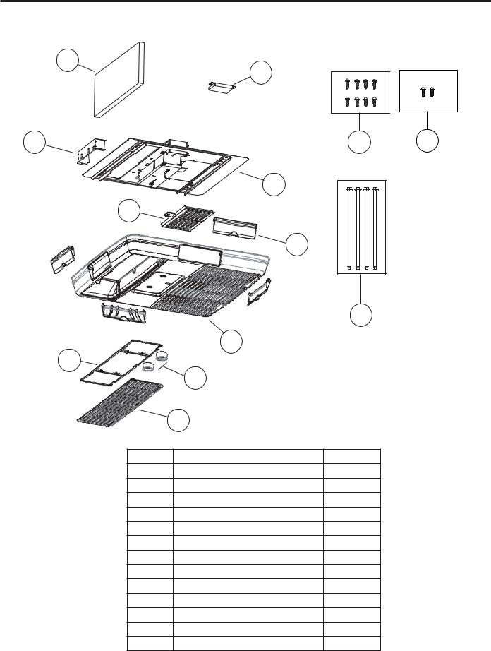
RARMN_ _- Mechanical Non-Ducted
Check the contents of the accessories supplied with your air conditioner as shown below:
10
8
9 |
12 |
13 |
7
6
5
|
|
11 |
|
4 |
|
2 |
|
|
|
3 |
|
|
1 |
|
Number |
Part Name |
QTY. |
1 |
Filter Cover |
1 |
2 |
Filter |
1 |
3 |
Knobs |
2 |
4 |
Ceiling Panel |
1 |
5 |
Side Discharge Ports |
4 |
6 |
Direct Discharge Guide |
1 |
7 |
Mounting template |
1 |
8 |
Junction Box Cover |
1 |
9 |
Connection Shield |
1 |
10 |
Air division baffle |
1 |
11 |
M8 Mounting Bolts |
4 |
12 |
Wood screws |
8 |
13 |
Sheet metal screws |
2 |
<![endif]>INSTRUCTIONS INSTALLATION
49-5000406 Rev. 5 |
5 |

<![endif]>INSTALLATION INSTRUCTIONS
Installation Instructions
RAREN_ _- Electronic Non-Ducted
Check the contents of the accessories supplied with your air conditioner as shown below:
8
10 11
7
6
5
4
9

 3 2
3 2 


1
Number |
Part Name |
QTY. |
1 |
Filter Cover |
1 |
2 |
Filter |
1 |
3 |
Ceiling Panel |
1 |
4 |
Side Discharge Ports |
4 |
5 |
Direct Discharge Guide |
1 |
6 |
Mounting template |
1 |
7 |
Blanking Plate |
1 |
8 |
Air division baffle |
1 |
9 |
M8 Mounting Bolts |
4 |
10 |
Wood screws |
8 |
11 |
Sheet metal screws |
8 |
6 |
49-5000406 Rev. 5 |

Installation Instructions
RARED_ _- Electronic Ducted
Check the contents of the accessories supplied with your air conditioner as shown below:
9 8
6
3 


 5 7
5 7
4
2
1
Number |
Part Name |
QTY. |
1 |
Filter Cover |
1 |
2 |
Filter |
1 |
3 |
Screw Cover (left and right) |
2 |
4 |
Ceiling Panel |
1 |
5 |
Mounting template |
1 |
6 |
Air division baffle |
1 |
7 |
M8 Mounting Bolts |
4 |
8 |
Wood Screws |
8 |
9 |
Sheet metal screws |
9 |
<![endif]>INSTRUCTIONS INSTALLATION
49-5000406 Rev. 5 |
7 |
<![endif]>INSTALLATION INSTRUCTIONS
Installation Instructions

 WARNING ELECTRICAL SHOCK HAZARD
Death or serious injury can result from failure to follow these instructions.
•Disconnect 115VAC and 12VDC power supply before beginning installation and/or servicing
•Ensure product is properly grounded according to the applicable codes
•Replace all parts and panels before operating
A. ROOF REQUIREMENTS AND DETERMINING LOCATION FOR INSTALLATION
Air conditioners covered in this manual are designed for installation on an RV’s roof.
Installation of this air conditioner must be in accordance with NFPA 1192 and NFPA 70.
For proper installation, there must be a 14 ñ» ” x 14 ñ» ” (+/-ï» ”) square opening in the roof and ceiling of the RV.
There must be 2 to 6 inches between the RV ceiling and roof.
Air conditioners covered in this manual are designed to fit over preexisting roof vent openings.
If a roof vent opening isn’t available, use the following guidelines:
8QLW LV WR EH LQVWDOOHG FHQWHUHG VLGH WR VLGH RQ WKH 59 URRI
8QLW LV WR EH LQVWDOOHG RQ D VHFWLRQ RI URRI ZKLFK LV OHYHO ZLWK respect to the RV roof if parked on a flat, level surface. Roof at the point of installation can have a maximum 15 degree tilt towards the front or rear of the RV.
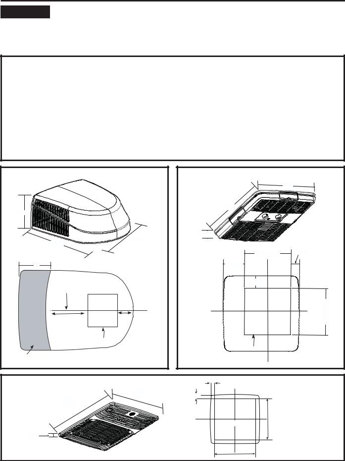
Figure 1: Outdoor Unit
Figure 2: Indoor Non-Ducted Unit Figure 3: Indoor Ducted Unit
Figure 1: Outdoor unit: |
|
Figure 2: Indoor Non-Ducted Unit: |
|
|
|
21” |
|
13 - 7/8” |
|
23” |
|
|
|
|
|
|
27 - 3/4” |
2 -1/2” |
|
32 - 7/8” |
|
|
|
|
|
|
|
|
|
14 - 3/8” |
2 - 5/8” |
18” |
|
6” |
|
|
|
3 - 3/8” |
|
Center Line of unit |
|
|
|
|
Front |
|
<![if ! IE]> <![endif]>- 14 |
13 - 3/4” |
4 - 3/4” |
|
<![if ! IE]> <![endif]>3/8” |
|
|
||
Roof opening |
|
|
|
|
|
Roof opening |
|
Keep at least 18” free of obstructions at rear of unit. |
|
|
|
Figure 3: Indoor Ducted Unit: |
|
1 - 3/8” |
|
|
|
|
|
|
17” |
1 - 3/8” |
|
17” |
|
|
|
|
|
14 - 3/8” |
|
|
|
Roof Opening |
|
5/8”
14 - 3/8”
8 |
49-5000406 Rev. 5 |

Installation Instructions
B.ROOF REQUIREMENTS AND PREPARATION
If a preexisting roof vent opening will be used:
8QVFUHZ DQG UHPRYH URRI YHQW IURP 59
2.Seal all holes and seams with a weather resistant sealant.
3.Measure the width and length of the vent opening. If the opening doesn’t comply with the requirements from section A, it must be resized.
If a preexisting opening will not be used, a new opening will be cut through both the roof and ceiling of the RV.
7KLV RSHQLQJ 0867 EH EHWZHHQ VWUXFWXUDO URRI members.
2.Do NOT cut structural roof members to create opening for this air conditioner. Doing so may cause damage to RV and air conditioner.
3.Do NOT create a low spot on the RV roof. Water can pool and may leak through the opening.
The square opening must be boxed with framing at least 3/4” thick to withstand the load from the compression bolts.
Be sure to provide an access hole for RV wiring toward the front of the 14 ñ» ” x 14 ñ» ” opening.
Roof and RV structure at point of install must be strong enough to support air conditioner without any deflection. If in doubt, please contact your RV
manufacturer. Deflection will allow water to pool at the air conditioner’s gasket, and may cause a leak.
C. ELECTRICAL REQUIREMENTS
These models require a 115-volt, 60-Hz protected with either a 15-amp or 20-amp time-delay fuse or circuit breaker (see table 1 on page 4).
8VH D PLQLPXP RI VKHDWKHG $:* FRSSHU ZLUH with ground.
Be sure that 16” of supply wire is passed through the framing. This ensures enough wire is available for an easy connection in the junction box.
D. PLACING UNIT ON ROOF
CAUTION |
LIFTING HAZARD. Ensure proper |
|
lifting methods and controls are |
|
used when lifting unit to the RV roof. Failure to do so can result in injury.
1.Remove unit from packaging and dispose of packaging.
2.Do not slide the unit on its mounting gasket.
'DPDJH WR JDVNHW FDQ FDXVH D OHDN 8VLQJ WZR people, lift the unit and place it over the prepared opening. The front of the unit must face the RV’s direction of travel. Damage to condenser fan and coil will occur if this instruction is not followed.
 WARNING It is important that these installation instructions are read and understood before installation and use.
Failure to securely install the unit to the RV before moving the RV may result in personal injury or death.
Do not operate the unit or recreational vehicle until the unit is fully secured on roof.
3.Bring the ceiling assembly with all provided mounting hardware into the RV. All work on the exterior of the RV is now complete.
<![endif]>INSTRUCTIONS INSTALLATION
49-5000406 Rev. 5 |
9 |
<![endif]>INSTALLATION INSTRUCTIONS
10
Installation Instructions
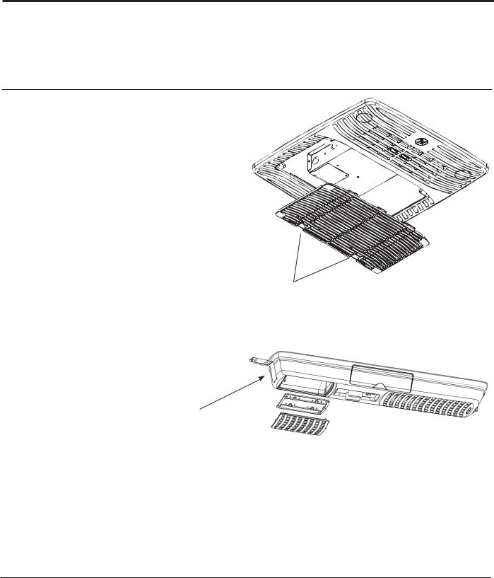
E.MECHANICAL NON-DUCTED INSTALLATION (RARMN_ _)
1.From inside the RV, double check the gasket’s position and alignment above the roof opening. Adjust if necessary. The air conditioner can be moved and adjusted by pushing upwards from inside the RV.
2.Reach through the base pan and pull the electrical power cord from the air conditioner through the ceiling opening.
3.Measure ceiling to roof thickness.
4.Cut rows from the bottom of the foam baffle according to the table below:
Ceiling to roof thickness (in) |
Rows to cut |
|
Minimum |
Maximum |
|
2 |
2.5 |
10 |
2.5 |
3 |
8 |
3.5 |
4 |
6 |
4.5 |
5 |
4 |
5 |
5.5 |
2 |
5.5 |
6 |
0 |
Best Practice:
Cut away one row at a time and check installation position of baffle. With the top foam compressed onto the air conditioner’s base pan, the bottom of the baffle should be flush to the ceiling opening.
5.Install 2 baffle retainer plates onto the ceiling assembly (Optional).
6.Place foam baffle into position between 2 retainer plates.
7.Push the mounting template into the roof opening, and begin hand-threading each of the 4 mounting bolts through the nuts in the base pan.
8.Tighten the 4 bolts evenly to 35 ± 5 inch pounds using a torque wrench at least rated for 0-60 in-lbs. Even compression is required to prevent leaks through the gasket.
9.Remove 6 pin connection cover from the ceiling assembly.
E.MECHANICAL CONTROL INSTALLATION (cont.)
10.Plug 6 pin connector from the roof mounted air conditioner into the electronic control box.
11.Reassemble the 6 pin connection cover to the ceiling assembly.
12.Remove junction box cover.
13.Route the 115 VAC power cord through the strain relief of the ceiling assembly. Tighten the strain relief, making sure not to damage the wires.
8VLQJ ZLUH FRQQHFWRUV FRQQHFW OLQH WR EODFN neutral to white, and ground to green.
8VLQJ HOHFWULFDO WDSH VHFXUH WKH FRQQHFWRU WR prevent any potential movement due to vehicle vibration.
16.Push wires and connections into the junction box. Reinstall junction box cover.
17.Align plastic ceiling panel to the metal assembly.
18.Install the 2 control knobs.
19.Install the 2 provided sheet metal screws to attach the plastic panel to the metal assembly. The filter must be removed to install these screws.
20.Apply pressure to the center of the plastic panel, drive the 2 wood screws at the location shown in the figure below. The air discharge doors should be partially open; otherwise, these screws will be difficult to drive.
21.Drive the remaining 6 wood screws. The air discharge doors should be hinged partially open; otherwise, these screws will be difficult to drive.
22.Assemble the filter to the plastic panel.
23.Installation is complete. Refer to “Controls” on page 12 before attempting to operate the air conditioner.
49-5000406 Rev. 5
Installation Instructions
F.ELECTRONIC DUCTED (RARED_ _) INSTALLATION
1.From inside the RV, double check the gasket’s position and alignment above the roof opening. Adjust if necessary. The air conditioner can be moved and adjusted by pushing upwards from inside the RV.
2.Reach through the base pan and pull the electrical power cord from the air conditioner through the ceiling opening.
3.Push the ceiling mounting template into the roof opening and begin hand-threading each of the 4 mounting bolts through the nuts in the base pan.
4.Tighten the 4 bolts evenly to 35 ± 5 inch pounds using a torque wrench at least rated for 0-60 in-lbs. Even compression is required to prevent leaks through the gasket.
5.Place dividing baffle into position on the ceiling assembly. Ensure baffle is pressed against the base pan, forming an airtight seal.
6.Mount the dividing baffle to the mounting template using three screws.
7.Mount the dividing baffle to the framing timber using two screws on each side, creating an airtight seal.
8.Mount the Main Control Box (RARMC_ _) to the mounting template using four screws.
9.Remove three screws from main control box, allowing the bottom section to hinge open. Control board is now visible and accessible.
10.Route the 115 VAC power cord through the strain relief of the control box. Tighten the strain relief, making sure not to damage the wires.
8VLQJ ZLUH FRQQHFWRUV FRQQHFW OLQH WR EODFN neutral to white, and ground to green.
8VLQJ HOHFWULFDO WDSH VHFXUH WKH FRQQHFWRUV WR prevent any potential movement due to vehicle vibration.
5RXWH WKH SLQ FRQQHFWRU WKURXJK WKH 8 6KDSHG opening of the control box. Mate 6 pin connector to the control box’s wire harness.
8VLQJ ZLUH FRQQHFWRUV FRQQHFW IXUQDFH ZLUHV
(blue), 3 thermostat wires (red, yellow, black), and two 12 VDC battery wires (red and black).
F.ELECTRONIC DUCTED (RARED_ _) INSTALLATION
15.The Indoor Coil Freeze sensor should be installed in the Thermistor Well on the outdoor unit (pictured below). The sensor has a 2-pin connector that needs to be plugged into “T2” on the circuit board. If the sensor is not installed in the outdoor unit, then install the one provided with the main control (RARMC_ _). Heat-Pump models also have a 4-pin connector that needs to be plugged into “T4”.
 Thermistor Well
16.Rotate lower section of control box upwards, making sure not to crush any wires. Drive three screws, securing the control box closed.
17.Align plastic ceiling panel to the metal assembly.
18.Install the 6 provided sheet metal screws to attach the plastic panel to the metal assembly. The filter and screw covers must be removed to install these screws.
19.Assemble the filter and screw covers to the plastic panel.
20.Installation is complete. Refer to thermostat operating instructions before attempting to operate.
Note for RARED_ _ models the mounting template can be installed prior to placing the rooftop unit on the coach per the following sequence:
1.Measure and attach the dividing baffle to the mounting template using 3 screws.
2.Push the mounting template into the roof opening and drive 4 screws through the plate holes and into the roof of the coach.
3.Follow steps 7-12
4.Follow step 14
5.Follow steps 1-2
6.Hand thread the mounting bolts through the mounting template and into the corresponding holes in the rooftop unit
7.Follow step 4
8.Follow Step 13
9.Follow Steps 15-20
<![endif]>INSTRUCTIONS INSTALLATION
49-5000406 Rev. 5 |
11 |

<![endif]>USING THE AIR CONDITIONER
Controls
Features and appearance will vary.
1 |
4 |
OFF
2 |
3 |
|
Air Conditioner Controls
Controls
1. Power Off
The air conditioner is off in this position.
2. Air Conditioning Modes
In these positions, the compressor and fans will run to provide cold air. The three modes correspond to low, medium, and high fan speeds.
3. Fan Only Modes
In these modes, the fans will run to circulate air in the RV. The three modes correspond to low, medium, and high fan speeds.
4. Temperature Selection
This knob determines the room set point temperature. Turn this knob to increase or decrease how cold the air conditioner will make the room.
OFF |
Position |
|
|
|
|
|
|
2B |
Position |
Position |
|
1A |
1B |
Position |
|
|
|
|
|
2A |

 CAUTION
To prevent circuit breaker from tripping, wait a minimum of 3 minutes between turning the compressor off and then back on (i.e. wait 3 minutes before moving the dial from position 1A to 1B back to 1A or moving from position 2A to 2B back to 2A (pictured above)
12 |
49-5000406 Rev. 5 |

Using the Air Conditioner
IMPORTANT:
•When you turn off the air conditioner, wait at least 3 minutes before turning it back on. This prevents the compressor from overloading. This 3 minute delay also applies when switching from cool mode to fan and back.
•Do not operate your air conditioner in the Cool mode when the outside temperature is below 60°F (15° C). The inside evaporator coil may freeze up, and the air conditioner will not operate properly.
Air Direction
8VH WKH OHYHU WR RSHQ RU FORVH YHQW RQ IDFH RI FRQWURO panel.
Open or close 4 side ports to adjust airflow from the air conditioner.


 Lever is located


 between the two


 knobs
knobs
Front View
Normal Operating Sounds
When your air conditioner is operating normally, you may hear sounds such as:
Ŷ 'URSOHWV RI ZDWHU KLWWLQJ WKH FRQGHQVHU FDXVLQJ D SLQJLQJ RU FOLFNLQJ VRXQG 7KH ZDWHU GURSOHWV KHOS FRRO WKH condenser.
Ŷ $LU PRYHPHQW IURP WKH IDQ
Ŷ &OLFNV IURP WKH FRQWURO F\FOLQJ Ŷ $ KXP RU SXOVDWLQJ QRLVH FDXVHG E\ WKH FRPSUHVVRU F\FOLQJ RQ DQG RII
<![endif]>CONDITIONER AIR THE USING
49-5000406 Rev. 5 |
13 |
<![endif]>CARE AND CLEANING
Care and Cleaning
Indoor Panel
Turn the air conditioner off and disconnect power from the air conditioner before cleaning.
To clean, use water and a mild detergent. Do not use bleach or abrasives.
Air Filter
The air filter should be checked every 2 weeks and cleaned if necessary.
DO NOT operate the air conditioner without a filter because dirt and lint will clog it and reduce performance.
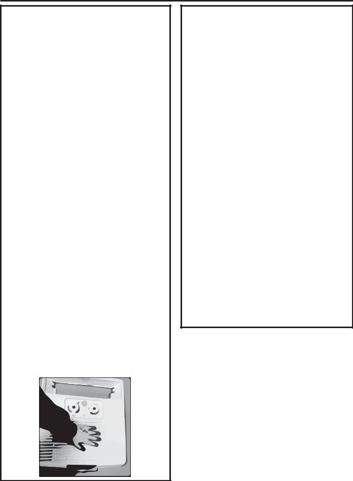
Cleaning the Air Filter
1. Turn off the air conditioner.
2. Remove the air filter cover per the figures on the right
|
to gain access to the filter. |
|
|
8VH D YDFXXP FOHDQHU WR FOHDQ DLU ILOWHU ,I WKH DLU |
|
||
|
filter is very dirty, wash it in warm water with a mild |
|
|
|
detergent. Do not wash the air filter in the dishwasher |
|
|
|
or use any chemical cleaners. Air dry the air filter |
|
|
|
completely before replacing to ensure maximum |
|
|
|
efficiency. |
Push both tabs toward the GE logo to release the cover. |
|
4. |
Reassemble the air filter to the grill. |
||
|
|||
5. |
Carefully reassemble the grill and filter assembly to |
|
|
|
the main panel. |
|
|
6. |
Turn on the air conditioner. |
|
|
Open front vent and push on the back side of the filter to release the cover.
Annual Maintenance
Your air conditioner needs annual maintenance to help ensure steady, top performance throughout the year.
Call your local authorized dealer to schedule an annual checkup. The expense of an annual inspection is your responsibility.
14 |
49-5000406 Rev. 5 |

Troubleshooting Tips... Before you call for service
Save time and money! Review the charts on the following pages first and you may not need to call for service.
Problem |
Possible Cause |
What To Do |
|
Air Conditioner |
An RV fuse has blown, or circuit |
Replace the fuse or reset the circuit breaker. If the problem |
|
does not operate |
breaker has tripped. |
continues, call an electrician. See “Electrical Requirements.” |
|
|
The mode setting is in the OFF |
Press POWER or turn the Mode control to an active setting. |
|
|
position. |
|
|
|
The local power has failed. |
Wait for power to be restored. |
|
Air conditioner |
Too many appliances are being used |
8QSOXJ RU UHORFDWH DSSOLDQFHV WKDW VKDUH WKH VDPH FLUFXLW |
|
blows fuses |
on the same circuit. |
|
|
or trips circuit |
|
|
|
Time-delay fuse or circuit breaker of |
Replace with a time-delay fuse or circuit breaker of the |
||
breakers |
|||
the wrong capacity is being used. |
correct capacity. See “Electrical Requirements.” |
||
|
|||
|
You are trying to restart the air |
Wait at least 3 minutes after turning off the air conditioner |
|
|
conditioner too soon after turning off |
before trying to restart the air conditioner. |
|
|
the air conditioner. |
|
|
Air conditioner |
The air conditioner is in a heavily |
8VH H[KDXVW YHQW IDQV ZKLOH FRRNLQJ RU EDWKLQJ DQG WU\ QRW |
|
seems to run too |
occupied room, or heat-producing |
to use heat producing appliances during the hottest part of |
|
much |
appliances are in use in the room. |
the day. A higher capacity air conditioner may be required |
|
|
|
depending on the size of the room being cooled. |
|
Air conditioner |
The air conditioner is not properly |
Check the cooling capabilities of your RV air conditioner. |
|
cycles on and off |
sized for your RV. |
|
|
too much or does |
|
|
|
The filter is dirty or obstructed by |
Clean the filter. |
||
not cool room in |
|||
debris. |
|
||
cooling mode |
|
||
|
There is excessive heat or moisture |
8VH D IDQ WR H[KDXVW KHDW RU PRLVWXUH IURP WKH URRP 7U\ QRW |
|
|
(open container cooking, showers, |
to use heat-producing appliances during the hottest part of |
|
|
etc.) in the room. |
the day. |
|
|
The louvers or ducts are closed. |
Make sure louvers are open. |
|
|
The outside temperature is below |
Do not try to operate your air conditioner in the cooling mode |
|
|
60°F (15°C). |
when the outside temperature is below 60°F (15°C). |
|
|
The temperature of the room you are |
Allow extra time for the air conditioner to cool off a very hot |
|
|
trying to cool is extremely hot. |
room. |
|
|
Windows or doors to the outside are |
Close all windows and doors. |
|
|
open. |
|
|
|
The Temperature control is not at a |
Adjust the TEMP control to a cooler setting by pressing the |
|
|
cool enough setting. |
minus button to reduce the temperature. Set the Fan Speed |
|
|
|
control to the highest setting. |
|
|
Wall thermostat improperly installed |
Verify proper installation of Wall Thermostat per installation |
|
|
|
instructions (pg. 5 …not on exterior wall or in direct |
|
|
|
sunlight… …in an area affected by a vent or duct…) |
|
Water drips from |
The indoor coil may be frozen. |
De-ice by running the fan only until clear. |
|
cabinet into your |
|
|
|
The air conditioner’s mounting gasket |
Check mounting bolts and tighten to 45 ± 5 in-lbs if |
||
house |
|||
may not be sealed against the roof. |
necessary. |
||
|
<![endif]>TROUBLESHOOTING
49-5000406 Rev. 5 |
15 |

<![endif]>SCHEMATIC DIAGRAMS
Schematic Diagrams
RVAC Roof Top Units, Cool Only |
RVHC Roof Top Units, Heat-Pump |
ARC13AHC_ _ _ ; ARC13AAC_ _ _ ; ARC15AAC_ _ _ |
ARH13AHC_ _ _ ; ARH15AAC_ _ _ |
Mechanical Ceiling Assembly |
Electronic Controls |
RARMN1A_ |
RARWT_ _ ; RARMC_ _ ; RAREC_ _ |
16 |
49-5000406 Rev. 5 |

GE Appliances Air Conditioner Limited Warranty
All warranty service must be provided by certified RV Service Centers.
To schedule service call 1-877-540-7837
Have serial number and model number available when calling for service.
For The Period Of: |
GE Appliances Will Replace: |
Two Years |
Any part of the air conditioner which fails due to a defect in materials or workmanship. |
From the date of the |
During this limited two-year warranty, GE Appliances will also cover all labor and |
original purchase |
related service to replace the defective part. |
What GE Appliances Will Not Cover:
ŶImproper installation, delivery or maintenance. If you have an installation problem, or if the air conditioner is of improper cooling capacity for the intended use, contact your dealer or installer. You are responsible for providing adequate electrical connecting facilities.
ŶFailure of the product resulting from modifications to the product or due to unreasonable use including failure to provide reasonable and necessary maintenance.
Ŷ /DERU QHFHVVDU\ WR PRYH WKH XQLW WR D ORFDWLRQ ZKHUH it is accessible for service by an individual technician.
ŶReplacement of house fuses or resetting of circuit breakers.
ŶDamage to the product caused by improper power supply voltage, accident, fire, floods or acts of God.
ŶIncidental or consequential damage caused by possible defects with this air conditioner.
ŶDamage caused after delivery.
EXCLUSION OF IMPLIED WARRANTIES—Your sole and exclusive remedy is product repair as provided in this Limited Warranty. Any implied warranties, including the implied warranties of merchantability or fitness for a particular purpose, are limited to two years or the shortest period allowed by law.
This limited warranty is extended to the original purchaser and any succeeding owner for products purchased
IRU 59 XVH ZLWKLQ WKH 86$ DQG &DQDGD ,I WKH SURGXFW LV ORFDWHG LQ DQ DUHD ZKHUH VHUYLFH E\ DQ DXWKRUL]HG 59 servicer is not available, you may be required to bring the product to an authorized service location for service. Authorized GE Service location for service.
Some states do not allow the exclusion or limitation of incidental or consequential damages. This limited warranty gives you specific legal rights, and you may also have other rights which vary from state to state. To know what your legal rights are, consult your local or state consumer affairs office or your state’s Attorney General.
Warrantor: GE Appliances, a Haier company
Louisville, KY 40225
<![endif]>WARRANTY LIMITED
| <![if ! IE]> <![endif]>is date |
<![if ! IE]> <![endif]>Staple |
| <![if ! IE]> <![endif]>obtain to needed |
<![if ! IE]> <![endif]>.here receipt your |
| <![if ! IE]> <![endif]>.warranty the under service |
<![if ! IE]> <![endif]>purchase original the of Proof |
|
|
49-5000406 Rev. 5 |
17 |
 Loading...