


AJHS10DCBM1
GE AJHS10DCBM1, AJHS08DCBM1, AJHS08ASBM1, AJES12DCBM1, AJES10DSBM1 Owner’s Manual
...
wvvw.GEAppliances.com
©
©
Safely Instructions ......... 2, 3
Operating Instructions
Controls_Control I{a_obs .... 8, 9
Controls---Touch Pads ....... 4-6
Care and Cleaning
Air Filter ................... 11
Front Grille ................. 10
Grille and Case .............. 10
Outdoor Coils ............... l 0
Installation Instructions
Before You Begin .......... 19, 13
Installing a J-Model in
an Existing _4'all Case ...... 13, 14
Through-the-_'all
Installation--Optional ........ 15
Window Installation--
Optional on models
so equipped .............. 16-91
Troubleshooting Tips ........ 92
Nomml Operating Sounds .... 92
Consumer Support
Consumer Support ... Back Coxer
_A'anantv ................... 93
Write themodel andserial numbershere:
Model #
Serial #
Find these nmnbers on a label on the ti'ont
ot the base pan behind the fl'ont grille.
Cool Ordy: A,[CH O& 10 ACB
4!(:H la 12 I)CB
41cq 06 t_cB
A!(:Q o& lo ACB
Aj(:Q m, 12 D(:B
AJ(;S 06 LCB
4!(:s o_,',m AC/J
4!(:s 09, m, 12 D(:B
H_,at/Cooh 4/EH 12 DCB
4flcs 06 [_sB
4fl,;s o_s, A,S'B
4fl';s 09, m, 12 DCB
4flcs lo DSB
Heat P'ump: 4/H5" 08 ASB
41HS o& lo DCB
Conditionneurs d'air
La section frangaise commence a la page 24
Acondicionadores
Aire
La seccion en espa#ol empieza en la pag&a 47
TINSEA380JBRZ 49-7485 02-04Jfl
IMPORTANTSAFETYINFORMATION.
READALLINSTRUCTIONSBEFOREUSING.
A WARNING'!
For your safe_ the information in this manual must be followed to minimize the risk of fire, electric
shock or personal injury.
SAFETYPRECAUTIONS
iiiiiiiiiiii_iii
iiiiiiiiiiii_iii
iiiiiiiiiiii_iii
Use this appliance only %r its intended
puq)ose as described in this Owner's
Manual.
This air conditioner must be properly
installed ira accordance with the
Installation Instructions 1)efore it is used,
Nexer unplug yonr air conditioner 1)y
pulling on fl_e power cord. Always gaiI)
plug fimgv and pull straight out flom the
receptacle.
Repair or replace immediately all elecwic
service cords that haxe become frwed or
otherwise damaged. Do not use a cord
that shows cracks or abrasion damage
along its length or at either the plug or
connector end.
Turn the mode control OFFand unplug
your air conditioner 1)efore making any
repairs or cleaning.
NOTE:Westronglyrecommendthat anyservicing
beperformedbya qualifiedindividual
For your safety...do not store or use
combustible mamrials, g_soline or other
flammable vapot_ or liquids ira the vicinity
of this or any other appliance.
All air conditioners contain refligerants,
which under federal law must be remoxed
prior to product disposal. If you are g>tting
rid of an old product wifl] refl-igerants,
check with the company handling disposal
about what to do.
HOWTOCONNECTELECTRICITY
Do not, under any circumstances, cut or remove
the third (ground) prong from the power cord.
For personal safety, this appliance must be
properly grounded.
The power cord of this appliance is equipped
with a 3-prong (grounding) ping which
mares with a standard 3q)rong (grounding)
wall outlet m minimize the possibility of
electric shock hazard flom this appliance.
Haxe the wall outlet and circuit checked
by a qualified electrician to make sure the
outlet is properly grounded.
Where a 2-prong wall ontlet is encounmred,
it is your personal responsibility and
obligauon m lame it replaced with a properly
grounded 3-prong wall outlet.
The air conditioner should always be plugged
into its own individual electrical outlet which
has a xoltage rating that matches the rating
plate.
This provides the best performance and also
prevents oxerloading house wiring circuits
which could cause a fire hazard flom
oxerheated wires.
See the Installation Instructions, Electrical
Requirements section for specific electrical
connection requirements.
2

www.GEAppliances.com
WARNING!
USEOFEXTENSIONCORDS--115-Voltmodelsonly
Because of potential safety hazards under
certain conditions, we strongly recommend
against the use of an extension cord.
Howe_; ifvon n]nst rise an extension cord,
it is absolutely necessm T flint it be a UL-listed,
14 gauge, 3-wire grounding type appliance
extension cord having a grounding type plug
and outlet and tilat rite electrical rating of
tile cord be 15 ampeies (minimum) and
125 _lts.
CAUtiON:
DONOT use an extension cord with any of the
230/208 volt models.
USEOFADAPTERPLUGS--115-Vo/tmodelsonly
Because of potential safety hazards under
certain conditions, we strongly recommend
against the use of an adapter plug.
Howex>i; if you nmst nse an adaptei; where
local codes permit, a temporary connection
may be made m a properly grounded
2-prong wall outlet by use of a UL-listed
adapter availahle at most local hardware
StoI'es.
When disconnecting tile power cord flom
tile adapml; always hold the adapter in place
with one hand while pulling tim power cord
plug witil the otiler hand. It"this is not done,
the adapter ground mnninal is x>rv likely to
break with repeated use.
If the adapter ground tem]inal breaks,
DONOTUSEthe air conditioner until a
proper gTonnd has been established.
The larger slot in tile adaptor mnst be
aligned with the larger slot in tile wall
outlet to provide proper polarity in tile
connection of the power cord.
Attachingthe adapter groundtermbal to a waft
outlet coverscrew does not groundtheappliance
unlessthecoverscrewis metal,notlesulated,and
thewaft outlet isgroundedthroughthe housewiring.
Youshouldhavethe circuitcheckedbya qualified
electricianto makesuretheoutlet is properly
grounded.
READANDFOLLOWTHISSAFETYINFORMATIONCAREFULLY.
SAVETHESEINSTRUCtiONS
3
Aboutthecontrolsontheair conditioner--modelswith touchpads.
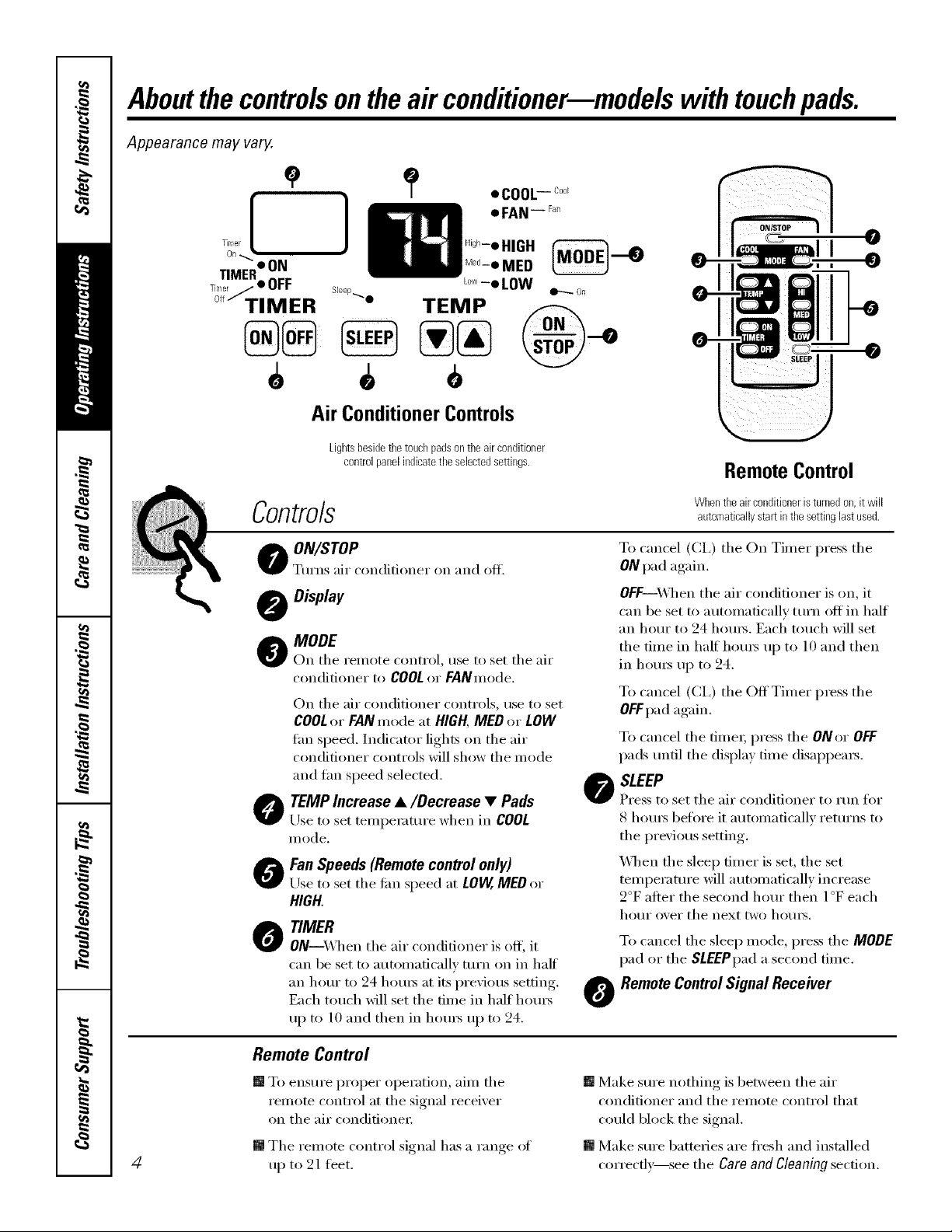
Appearance may vary.
]
Air ConditionerControls
Lightsbesidethetouchpadsontheairconditioner
controlpanelindicatetheselectedsettings.
RemoteControl
Controls
Whentheairconditioneristurnedon,it will
automaticallystartinthesettinglastused.
O ON/ITOPo o
Turn,_ air c nditi net on and off.
Display
_k MODE
r On tile remote control, rise to set tile air
conditioner to COOL or FANmode.
On tile air conditioner controls, use to set
COOLor FANmode at HIGH,MED or LOW
tim speed. Indicator lights on tile air
conditioner controls will show tile mode
and tim speed selected.
O TEMP Increase •/Decrease • Pads
Use to set temperature when in COOL
illode.
O an Speeds (Remote control only)
Use to set tile fiul speed at LOVV,MEDor
HIGH.
O TIMER
ON--\,_q/ell tile air conditioner is off, it
can be set to automatically mrn on in half
an horn" to 24 hours at its previous setting.
Each touch will set tile time in half horn's
up to lO and then in hem5 up to 24.
To cancel (CI,) tile On Timer press tile
ONpad again.
OFF--X&]/en the air conditioner is on, it
can be set to automatically turn off in half
an horn" to 24 hom_. Each touch will set
tile time in haft hom_ up to 10 and then
in hom_ up to 24.
To cancel (CI,) tile OffTimer press tile
OFFpad again.
To cancel tile timex; press tile Omor OFF
pads/mtil tile display time disappears.
O SLEEP
Press to set tile air conditioner to run for
S hom_ before it automatically returns to
tile previous setting.
X_]mn tile sleep timer is set, tile set
temperature will automatically increase
2°F alter tile second horn" then l °F each
ho/lI" over tile Ilext two NO/IIN.
To cancel tile sleep mode, press tile MODE
pad or tile SLEEPpada second tilne.
O RemoteControlSignal Receiver
4
Remote Control
[] To ensure proper operation, aim tile
remote control at tile signal receixer
on tile air condifione_:
[] Tile remote control si_mal has a range of
up to 21 feet.
[] Make sure nothing is between tile air
conditioner and tile remote control that
could block the signal.
[] Make sure batteries are fl'esh and installed
correcflx_see tile Care and gleaning section.

www.GEAppliances.com
COOLMODE
RemoteControl
l. Px_ssCOOLpad.
2.P*_ssLOW,IVIEDor HIpads to set desired fire speed.
3.Px_ssdieINCREASEA/DECREASETpadstoset the
desix_d temperature 60°F to 85°F in l°Fincrements.
ControlPanel
l. Pxess d_e MODEpad until tile COOLindicator lig]lt is
lit and the LOW, MEDor Hlindicator light is lit fbr
dm (]esix_(] thn speed.
2. Px_ss the INCREASE&/DECREASET pads to set the
(]esix_(] temperature 60°F to 85°F in l °F increments.
A them/ostat is used to maintain tile room
temperature. Tile compressor will e}cle on and off
to keep tile room at tile set level of comtbrt. Set die
thermostat at a lo_r nm-nber and die indoor air will
become coolex; Set tile themlostat at a big]mr number
and tile indoor air will become _mnex;
NOTE:ff theair conditioner is off andis then turned on
while set toCOOL,it will take approximately3minutes for
the compressortostart and cooling tobegin.
CoolingDescriptions
ForNormal Cooling--Select the COOLmode and
HIGHor MEDtbn with a middle set temperature.
ForMaximumCooling--Selecttile COOLmode
and HIGHtim with a lowerset temperatm_.
ForQuieter& NighttimeCooling--Select tile COOLmode
and LOWfbnwid_a middle set temperature.
NOTE:If youswitch froma COOLsettingtoOFFerto
afansettingwaitatleast3minutesbeforeswitchingback
toaCOOLsetting.
Fan Switch
Tile thn switch is located behind tile ti'ont grille on the
control box. Access through a hole in control box.
_A]mn set at CYCLE(do_n) tile thn e_cles on and off.
When set at CONT(continuous, up) tile tim runs all tile
time prodding a rnox_ balanced mmperatm_. The unit
is shipped in tile CONTsetting.
FAN MODE
Use tile FANmode to pro\ide _dr circulation and
filtering without cooling. Since tim only settings do not
provkle cooling, a tempenmlre setting will not be
displa}ed.
RemoteControl
Px_ss FANpad. Press LOW,MEDor HI pads to set
desix_d thn speed.
ControlPanel
Px_ss die MODEpad until tile FANindicator light is lit
and tile LOW, MEOor HIindicator light is lit tbr the
desix_d tan speed.
Vent Control
T]_e vent control is located behind tile ti'ont grille on
tile right side of tile air (fischarge area. "_lmn set at
CLOSE,only tile air inside the room will be circulated
and conditioned. When set at OPEN,some inside air is
exhausted outside.
TO opell or close tile vent:
l. Remove tile ti'ont grille.
2. Remove tile vent card scx_.
3. Remove vent card, turn it over and replace it b}
locating rear hole in card over locating pin inside air
discharge and reattaching scre_ at fi'ont.
Theunitleavesthefactoryset attheCLOSEposition.
._Locating i_oie
Screwhole "_.
OPENposition
(Meshendtowardback)
Screwha
CLOSEposition
(Meshendtowardfront)
A# Direction
Horizont_fl lomers
on d_e fi'ont grille let
you control tile air
(lirection up and
doP_I/.
Remove the i]?ont
grille to a(!just the
vertical louvers
side-to_ide to
(fix_ct the air
left or fight.
Aboutthe controlsonthe air conditionermmodels with touchpads.
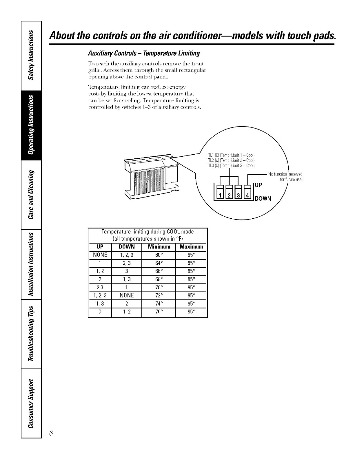
Auxiliary Controls- TemperatureLimiting
To reach the auxiliary controls remove the fl'ont
g_ille, Access them through the small rectangular
opening above the control panel.
Temperature limiting can reduce energy
costs by limiting the lowest temperature that
can be set for cooling. Temperature limiting is
controlled bv switches 1-3 of au_lia_w controls.
TL1(C){Temp.Limit1 Cod)
TL2(C){Temp.Limit2 Cool)
TL3(C}{Temp.Limit3 Cool}
UP
-- Nofunction(reserved
for futureuse)
DOWN
Temperaturelimiting during COOLmode
(all temperatures shown in °F)
UP DOWN Minimum Maximum
NONE 1,2,3 60° 85°
1 2,3 64° 85°
1,2 3 66° 85°
2 1,3 68° 85°
2,3 1 70° 85°
1,2, 3 NONE 72° 85°
1,3 2 74° 85°
3 1,2 76° 85°

Notes. www.GEAppliances.com
m
m
m
:X
7
Aboutthecontrolsontheair conditioner--modelswith controlknobs.
LOW
FAN
OFF • HIGH
r_j_l _ FAN
LOWI_ I I I _tLOW
HEAT'!I I yCOOL
HIGHlib I I Ill HIGH
HEAT--_" COOL
OFF
LOWm _ i LOW
FAN_COOL
HIGHi• I I •_ HIGH
FAN w_w COOL
S
/
/
8
MODECONTROL TEMPCONTROL
0
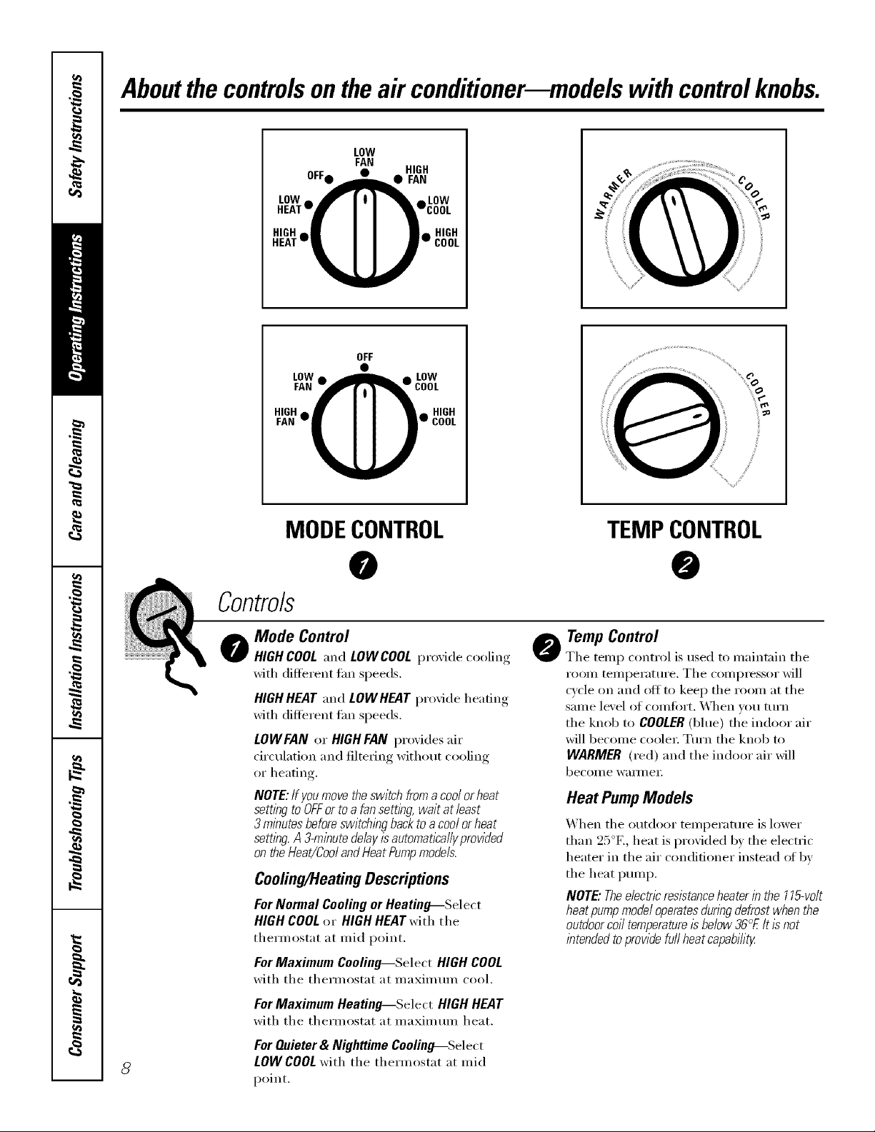
o Mode Control
HIGHCOOLand LOWCOOLl)r°_ide cooling
with different tm_ speeds,
HIGHHEATand LOWHEATprovide heating
with different Lm speeds,
LOWFAN or HIGH FAN provides air
circulation and filtering without cooling
or heating.
NOTE:If youmovetheswitchfromacoo/orheat
settingtoOFForto afansetting,waitat/east
3 minutesbeforeswitchingbacktoacoo/orheat
sembg.A3-minutefle/ayisautomat/ca//yprovided
ontheHeat/Coo/andHeatPumpmodels.
Cooling/HeatingDescriptions
ForNormal CoolingorHeating_Select
HIGHCOOLor HIGHHEATwith the
thermostat at mid point.
ForMaximum Cooling--Select HIGHCOOL
with the thermostat at maximum cool.
o TempControl
The temp control is used to maintain the
room temperature. The compressor will
cycle on and ott to kee I) the room at the
same level of comfort. _*\]/en you turll
the knob to COOLER(blue) the indoor air
will become coolex: Turn the knob to
WARMER (red) and the indoor air will
becoi/l e Wall/l eI:
Heat PumpModels
When the outdoor temperature is lower
than 25°F., heat is provided by the electric
heater in the air conditioner instead ot bv
the heat pump.
NOTE"Theelectricresistanceheaterinthe115-vo/t
heatpumpmode/operatesdunbgdefrostwhenthe
outdoorco//temperatureisbe/ow36°£it isnot
intendedtoprovidefurlheatcapability
ForMaximum Heating_$elect HIGH HEAT
with the thermostat at maximum heat.
For Quieter & Nighttime Cooling---.Select
LOW COOLwith the thermostat at mid
point.
vvww.GEAppliances.com
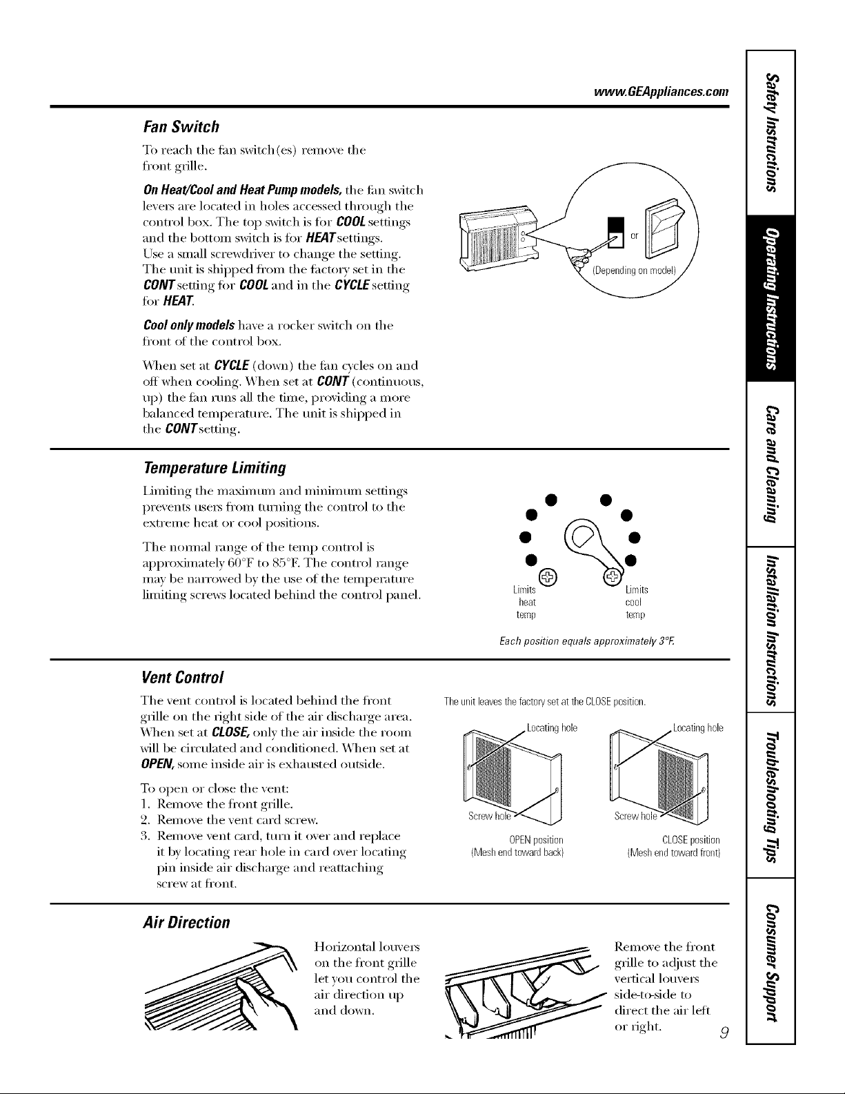
Fan Switch
To reach tile tim switch (es) remove tile
front grille.
OnHeagCool and Heat Pump models, tile tim switch
leveI_ are located in holes accessed through tile
control box. Tile top switch is fin" COOLsettings
and tile bottom sMtch is fin" H_lTsettings.
Use a small screwdriver to change tile setting.
Tile trait is shii)ped fl'Oll/ tile ti_ctory set ill tile
CONY setting tot COOLand in tile cgCtfsetting
tot HEAT
Coolonly models have a rocker switch on tile
front of tile control box.
_4qlen set at CYCLE(down) tile tim cycles on and
off when cooling. When set at CONT (continuous,
up) tile tim runs all tile time, providing a more
balanced telnI)eramre. Tile unit is shipped ill
tile CONTsetting.
Temperature Limiting
Limiting tile maMmum and minimum settings
prevents useI_ ti'oln turning tile control to tile
extrelne heat or cool positions.
Tile nom/al range of tile temp control is
approxinmtely 60°F to 85°E Tile control range
may be narrowed by tile use of tile telni)erature
lilniting screws located behind the control panel.
. %.
Limits@ Limits
heat cool
temp temp
Eachposition equals approximately 3°E
Vent Control
Tile vent control is located behind tile fl'ont
grille on tile fight side of tile air discharge area.
X'_qlell set at CLOSE,onl} tile air inside tile room
will be circulated and conditioned. When set at
OPEN, some inside air is exhausted outside.
To open or close tile vent:
1. Relnove tile fl'ont grille.
2. Relnove tile vent card screw.
3. Relnove vent card, turn it over and replace
it by locating rear hole in card over locating
pin inside air dischmge and ream_ching
scFew at Ji'ollt.
Ti_eunitleavesthefactorysetatthe CLOSEposition.
_hole
OPENposition
(Meshendtowardhack)
Screwhc
CLOSEposition
(Meshendtowardfront)
A# Direction
HolJzontnl lo/wei_
on tile fl'ont grille
let you control tile
air direction up
and down.
Reln_we tile fl'ont
grille to a(!iust the
vertical louve_
side-to-side to
direct the air lett
or fight.
Careand cleaning ofthe air conditioner..
Grille and Case
Turn the air conditioner off and remo_e the To clean, use water and a mild detergent.
plug, ti'on_ the wall outlet before cleaning, Do not use bleach or abrasives.
OutdoorCoils
The coils on the outdoor side of the air
conditioner should be checked regularly.
If they are clogged with dirt or soot they may be
professionally steam cleaned, a service available
through yore" GE se_wice outlet.
10
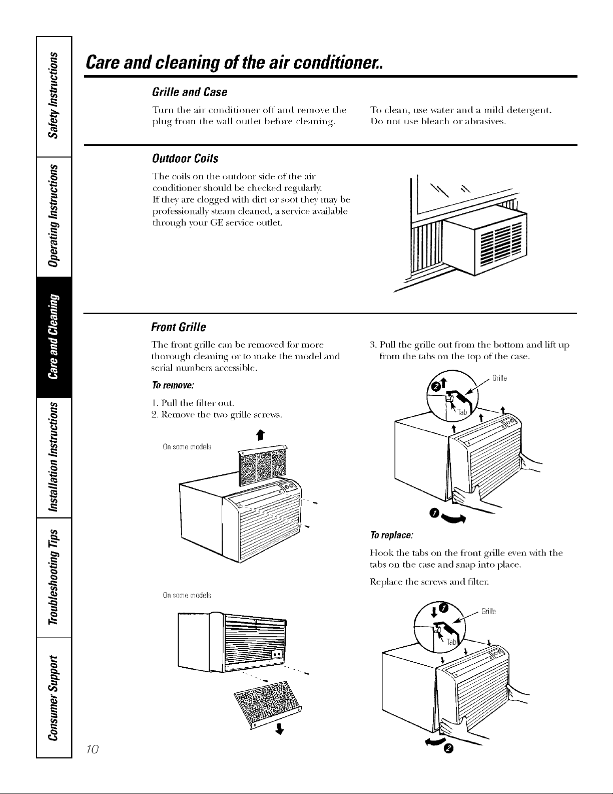
Front Grille
The fl'ont grille can be removed tot more
thorough cleaning or to make the model and
serial n/lillbeYs accessible.
Toremove:
1. Pull the filter out.
2. Remove the two grille scre_vs.
tt
Onsomemodels
Onsomemodels
3 Pull the r,Tille out fl'om the bottom and lift up
ti'om the tabs on the top of the case.
_ Grille
Toreplace:
Hook the tabs on the ti'ont grille even with the
tabs on the case and snap into place.
Replace the screws and filtei:
www.GEAppliances.com
Tomaintain optimum performance, clean the filter at least every30 days.
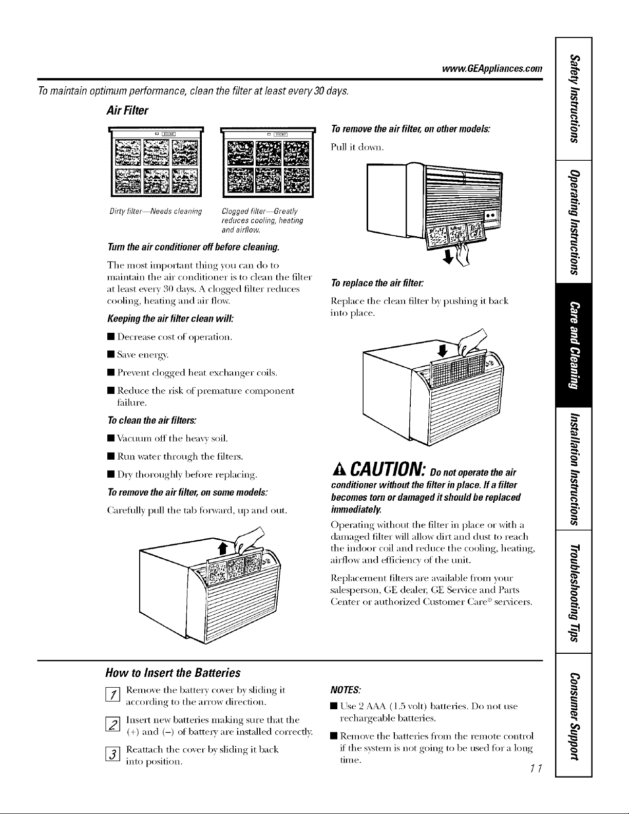
Air Filter
Toremove the a# filter, on uther models:
Pull it down.
Dirtyfilte_Needs cleaning Cloggedfilter Greatly
reducescooling,heating
andairflow,
Turnthe a# conditioner off before cleaning.
The most important thing you can do to
maintain the air conditioner is to clean the filter
at least eve_T 30 days. A clogged filter reduces
cooling, heating and air flow.
Keeping the a# filler clean will:
• Decrease cost of operation,
• Save energy,,',
• Prevent clogged heat exchanger coils.
• ]),educe the risk of prematm'e component
fifilm'e.
Toclean the air filters:
• Vacumn off the heavv soil.
• ]/m_ wamr through the filte_.
• DIy thoroughly befi)re replacing.
Toremove the air filter, on somemodels:
Careflflly pull the tab forward, up and out.
Toreplace the air filter."
Replace the clean filter by l)ushing it back
into place.
CAUTION:oonutoperatetheair
conditioner without the filter in place. If a filter
becomes tornor damaged itshould be replaced
immediately.
Operating without the filter in place or with a
damaged filter will allow dirt and dtlst to reach
the indoor coil and reduce the cooling, heating,
air{low and efficiency (ff the trait.
Replacement filtexs are ax filable fl'om yore"
salesl)e_on, (;E deale_; (;E Sertice and Parts
Center or authorized ()lstomer Care _' servicers.
How to Insert the Batteries
] ]_.emove the battery ('oxer b) sliding it
according to the arrow direction.
] Insert new batteries making sure that the
(+) and (-) of batteI_' are installed correctlx:
] Reattach the coxer by sliding it back
into position.
NOTES:
• Use 2 _& (1.5 w)lt) batteries. Do not use
rechaxgeable batteries.
• Remove the batteries fl'om the xemote control
if the system is not going to be used fin" a long
tim e.
//
Installation
Instructions
Air Conditioner
I [] Questions? Call 800.GE.CARES (800.432.2737) or Visit our Website at: www.GEAppliances.com I
BEFORE YOU BEGIN
Read these instructions completely and
carefully.
• IMPORTANT - Savetheseinstructions
for local inspector's use.
• IMPORTANT - Observeallgoverning
codes and ordinances.
• Note to Installer - Be sure to leave these
instructions with the Consumer.
• Note to Consumer - Keep these instructions for
future reference.
° Skill level- Installation of this appliance requires
basic mechanical skills.
• Completion time - Approximately 1 hour
• We recommend that two people install this
product.
• Proper installation is the responsibility of the
installer.
• Product failure due to improper installation
is not covered under the Warranty.
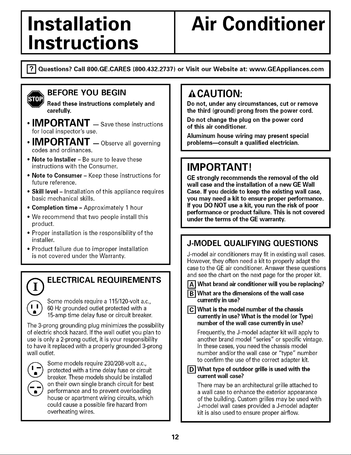
O ELECTRICAL REQUIREMENTS
Some models require a 115/120-volt a.c.,
60 Hz grounded outlet protected with a
15-amp time delay fuse or circuit breaker.
The 3-prong grounding plug minimizes the possibility
of electric shock hazard. If the wall outlet you plan to
use is only a 2-prong outlet, it is your responsibility
to have it replaced with a properly grounded 3-prong
wall outlet.
©
@
Some models require 230/208-volt a.c.,
protected with a time delay fuse or circuit
breaker. These models should be installed
on their own single branch circuit for best
performance and to prevent overloading
house or apartment wiring circuits, which
could cause a possible fire hazard from
overheating wires.
Z CAUTION:
Do not, under any circumstances, cut or remove
the third (ground) prong from the power cord.
Do not change the plug on the power cord
of this air conditioner.
Aluminum house wiring may present special
problems--consult a qualified electrician.
IMPORTANT!
GE strongly recommends the removal of the old
wall case and the installation of a new GE Wall
Case. If you decide to keep the existing wall case,
you may need a kit to ensure proper performance.
If you DO NOT use a kit, you run the risk of poor
performance or product failure. This is not covered
under the terms of the GE warranty.
J-MODEL QUALIFYING QUESTIONS
J-model air conditioners may fit in existing wall cases.
However, they often need a kit to properly adapt the
case to the GE air conditioner. Answer these questions
and see the chart on the next page for the proper kit.
[] What brand air conditioner will you be replacing?
What are the dimensions of the wall case
[] currently in use?
[] What isthe model number of the chassis
currently in use?What isthe model (or Type)
number of the wall case currently in use?
Frequently, the J-model adapter kit will apply to
another brand model "series" or specific vintage.
In these cases, you need the chassis model
number and/or the wall case or "type" number
to confirm the use of the correct adapter kit.
[] What type of outdoor grille isused with the
current wall case?
There may be an architectural grille attached to
a wall case to enhance the exterior appearance
of the building. Custom grilles may be used with
J-model wall cases provided a J-model adapter
kit is also used to ensure proper airflow.
12
Installation Instructions
Read these instructions completely and carefully,
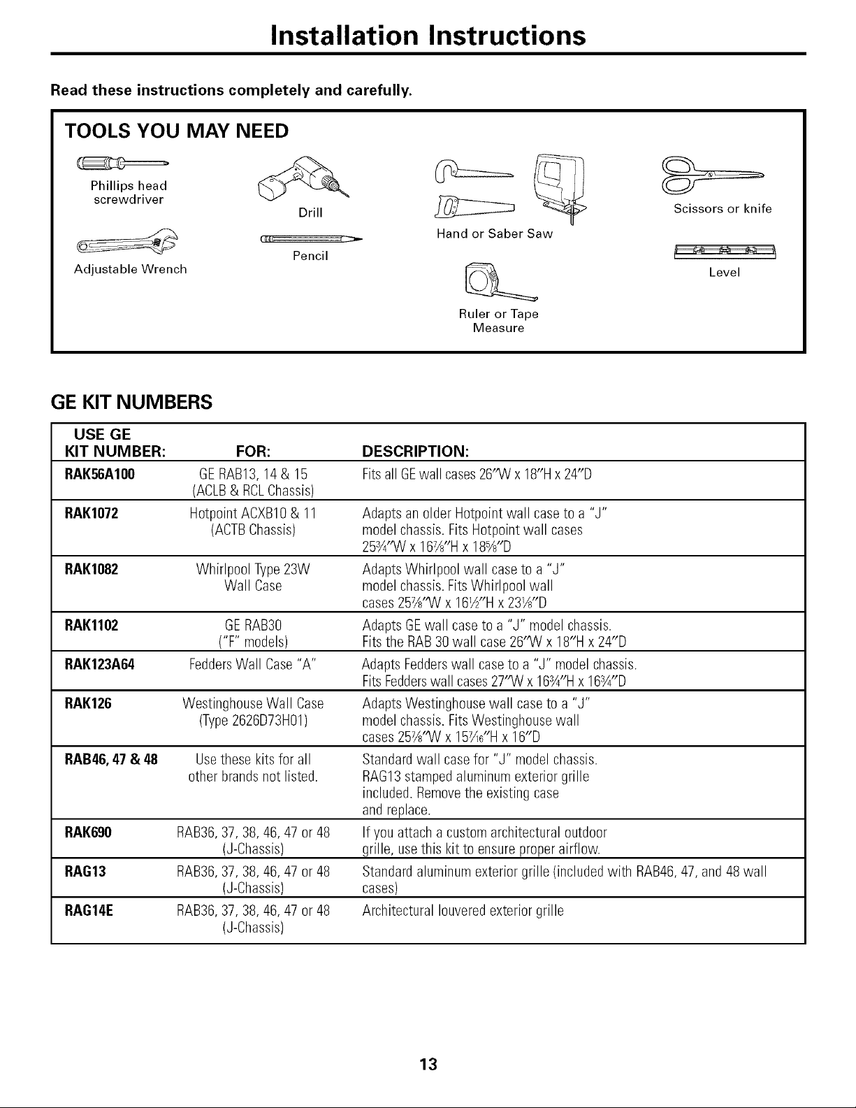
TOOLS YOU MAY NEED
Phillips head
screwdriver
Drill
Adjustable Wrench
Pencil
Hand or Saber Saw
Ruler or Tape
Measure
Scissors or knife
Level
GE KIT NUMBERS
USE GE
KIT NUMBER: FOR: DESCRIPTION:
RAK56A100 GERAB13,14 & 15 Fits all GEwall cases26"W x 18"Hx 24"D
(ACLB& RCLChassis)
RAK1072 Hotpoint ACXB10& 11 Adapts an older Hotpoint wall caseto a "J"
(ACTBChassis) model chassis. Fits Hotpoint wall cases
25¾"W x 167X'Hx 18_"D
RAK1082 Whirlpool Type23W AdaptsWhirlpool wall case to a "J"
Wall Case model chassis.FitsWhirlpool wall
cases257X'W x 16_"H x 23W'D
RAK1102 GERAB30 Adapts GEwall case to a "J" model chassis.
("F" models) Fitsthe RAB 30 wall case 26"W x 18"H x 24"D
RAK123A64 FeddersWall Case"A" Adapts Fedderswall caseto a "J" model chassis.
FitsFedderswall cases 27"W x 16SA"Hx 16SA"D
RAK126 Westinghouse Wall Case AdaptsWestinghouse wall case to a "J"
(Type2626D73H01) model chassis. FitsWestinghouse wall
cases257_"W x 157_6"Hx 16"D
RAB46, 47 & 48 Usethese kits for all Standardwall case for "J" model chassis.
other brands not listed. RAG13stamped aluminum exterior grille
included. Removethe existing case
and replace.
RAK690 RAB36,37, 38, 46, 47 or 48 If you attach a custom architectural outdoor
(J-Chassis) grille, usethis kit to ensure proper airflow.
RAG13 RAB36,37, 38, 46, 47 or 48 Standard aluminum exterior grille (included with RAB46,47,and 48 wall
(J-Chassis) cases)
RAG14E RAB36,37, 38, 46, 47 or 48 Architectural Iouvered exterior grille
(J-Chassis)
13
Installation Instructions
INSTALLING A J-MODEL IN AN EXISTING WALL CASE
Read these instructions completely and carefully.
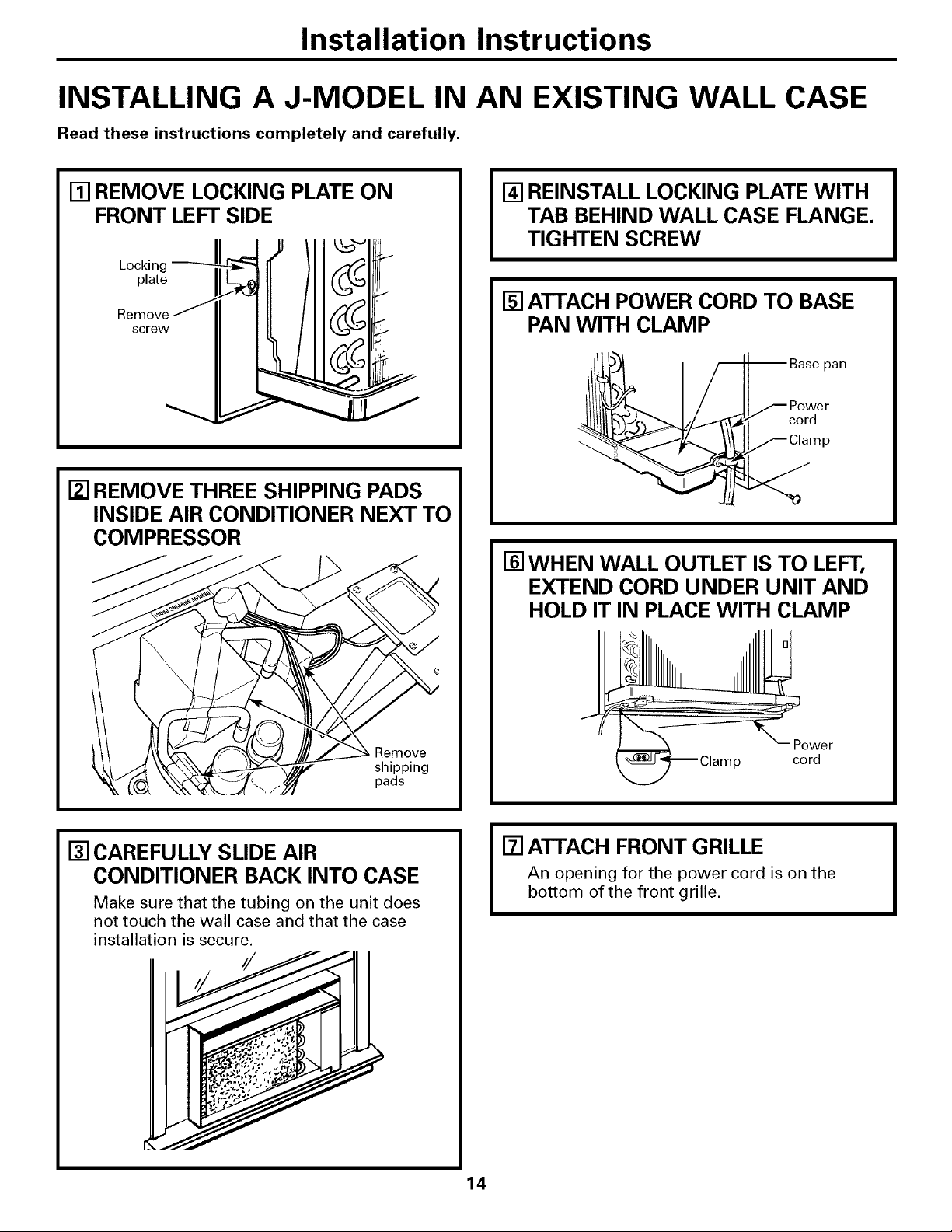
[] REMOVE LOCKING PLATE ON
FRONT LEFT SIDE
Locking
plate
Remove
screw
[] REMOVE THREE SHIPPING PADS
INSIDE AIR CONDITIONER NEXT TO
COMPRESSOR
Remove
shipping
pads
[] REINSTALL LOCKING PLATE WITH
TAB BEHIND WALL CASE FLANGE.
TIGHTEN SCREW
[] ATTACH POWER CORD TO BASE
PAN WITH CLAMP
pan
cord
P
[] WHEN WALL OUTLET IS TO LEFT,
EXTEND CORD UNDER UNIT AND
HOLD IT IN PLACE WITH CLAMP
Power
p cord
[] CAREFULLY SLIDE AIR
CONDITIONER BACK INTO CASE
Make sure that the tubing on the unit does
not touch the wall case and that the case
installation is secure.
[] ATTACH FRONT GRILLE
An opening for the power cord is on the
bottom of the front grille.
Installation Instructions
INSTALLING THROUGH THE WALL
Read these instructions completely and carefully.
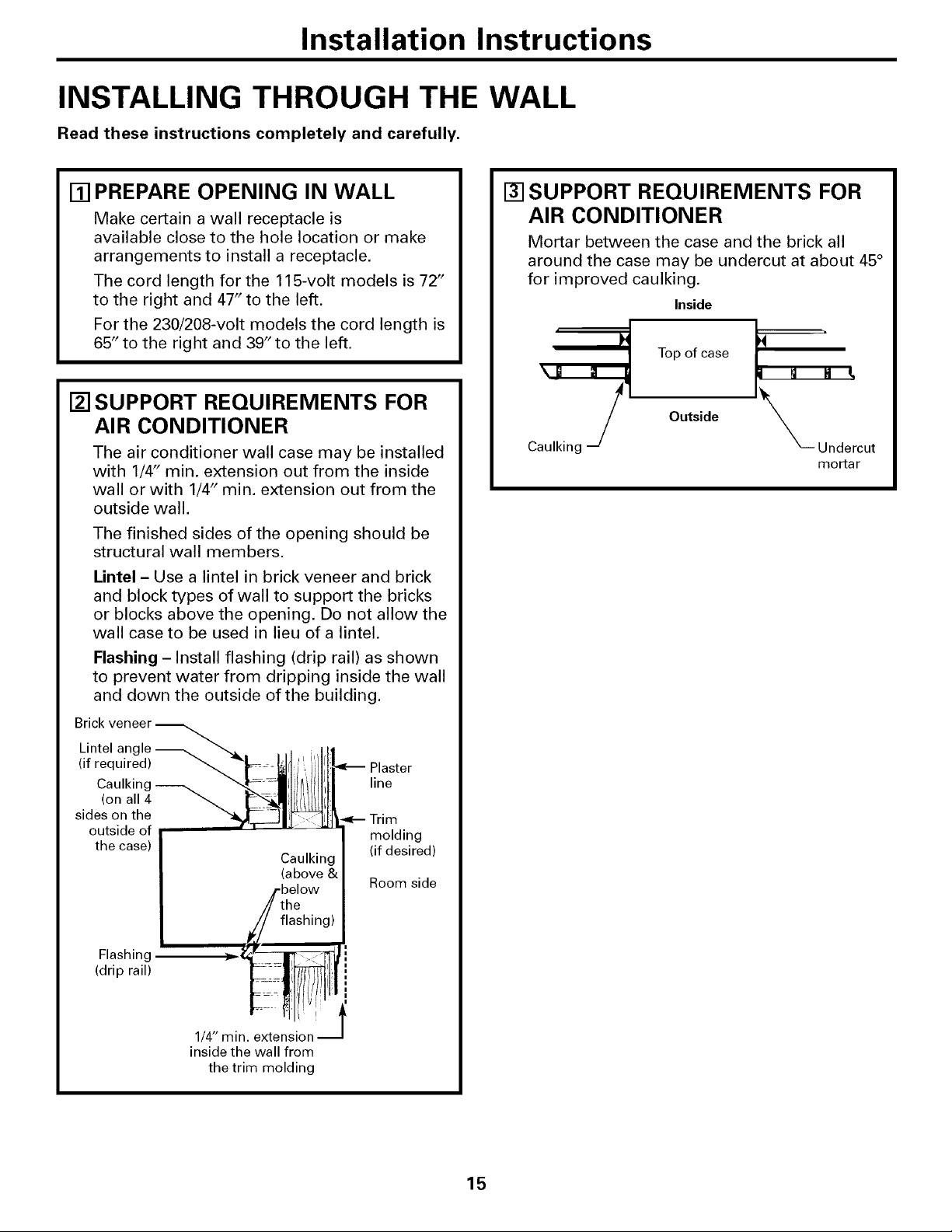
[] PREPARE OPENING IN WALL
Make certain a wall receptacle is
available close to the hole location or make
arrangements to install a receptacle.
The cord length for the 115-volt models is 72"
to the right and 47" to the left.
For the 230/208-volt models the cord length is
65" to the right and 39" to the left.
[] SUPPORT REQUIREMENTS FOR
AIR CONDITIONER
The air conditioner wall case may be installed
with 1/4" min. extension out from the inside
wall or with 1/4" min. extension out from the
outside wall.
The finished sides of the opening should be
structural wall members.
Lintel - Use a lintel in brick veneer and brick
and block types of wall to support the bricks
or blocks above the opening. Do not allow the
wall case to be used in lieu of a lintel.
Flashing - Install flashing (drip rail) as shown
to prevent water from dripping inside the wall
and down the outside of the building.
Brick
Lintel angle
(if required) _ Plaster
Caulking _ line
(on all 4_
sides on the Trim
outside of molding
the case) (if desired)
Room side
Flashing
(drip rail)
f
1/4" min. extension
inside the wall from
the trim molding
[] SUPPORT REQUIREMENTS FOR
AIR CONDITIONER
Mortar between the case and the brick all
around the case may be undercut at about 45°
for improved caulking.
Inside
Caulking
Top of case
Outside
_" Undercut
mortar
15
Installation Instructions
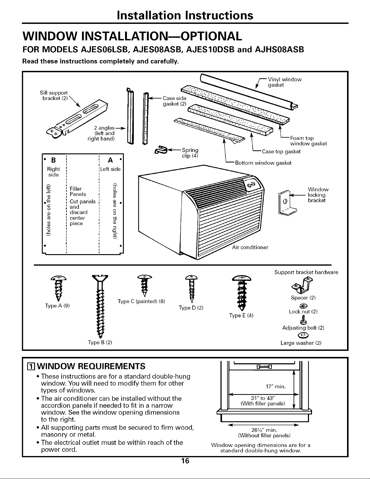
WINDOW INSTALLATION--OPTIONAL
FOR MODELS AJES06LSB, AJES08ASB, AJES10DSB and AJHS08ASB
Read these instructions completely and carefully.
Sill support
bracket (2) X_k
2 angles---_-
(left and
right hand)
• B
Right
side
03
03
03
Filler
Panels
Cut panels
and
discard
center
piece
(1)
63
_o
o
(I)
i •
I
I I"
Type A (9)
Type B (2)
Case side
gasket (2)
F inyl window
gasket
r
Foam top
_' _ window gasket
15_'_ SlPri_4_ \ Case top gasket
P _ Bottom window gasket
Window
_ locking
bracket
Support bracket hardware
Type C (painted) (6) Spacer (2)
Type D (2) 1_
Lock nut (2)
Type E (4) d
Adjusting bolt (2)
Large washer (2)
[] WINDOW REQUIREMENTS
* These instructions are for a standard double-hung
window. You will need to modify them for other
types of windows.
• The air conditioner can be installed without the
accordion panels if needed to fit in a narrow
window. See the window opening dimensions
to the right.
• All supporting parts must be secured to firm wood,
masonry or metal.
• The electrical outlet must be within reach of the
power cord,
16
r-
I
I
B===_
17" min.
31" to 43"
(With filler panels)
261/4"min.
(Without filler panels)
Window opening dimensions are for a
standard double-hung window.

Installation Instructions
1-21STORIVIWINDOW REQUIREMENTS
A storm window frame will not allow the air
conditioner to tilt towards the outside and will
keep it from draining properly. To adjust for this,
attach a piece of wood to the stool.
1/2"higher _ ,_./Wood
than A
frame
Storm" I] II
window /I II
frame /_ II
WOOD PIECES:
WIDTH: 2"
LENGTH: Long enough to fit inside the window
frame.
THICKNESS: To determine the thickness, place a
piece of wood on the stool to make it 1/2" higher
than the top of the storm window frame.
Attach securely with nails or screws provided by
the installer.
r_REMOVE AIR CONDITIONER FROM CASE
[] Remove the front grille. See the Care and
Cleaning section,
[] Find the locking plate located on the front
left side,
[] Remove the screw and the locking plate to
Locking
plate
screw
unlock the air conditioner.
[]
[]
Remove and discard the shipping screw
on the back of the air conditioner to allow
removal of the air conditioner from the
case.
Pull the bottom corners of the air
conditioner and slide it out of the case.
[] Remove the three shipping pads inside the air
conditioner next to the compressor.
Remove
shipping
pads
[] Remove the rear grille that is taped to the back
of the case. Remove the packet of screws taped
to the back of the grille. While holding the grille
at a 45° angle, insert it into the clips at the top of
the case and push the bottom in. Keep slight
upward pressure on the grille until it fits flush
with the bottom of the case.
If attaching the grille
from the outside of
the case use the 2
long screws.
If attaching the grille
on the inside of the
case use the 2 short
screws.
Clips
Insert the 2 long screws on
the outside
I /llllllllllllllllllllllllllllllllllllllllllll/I,
/llllllllllllllllllllllllllllllllllllllllllllt/I
/llllllllllllllllllllllllllllllllllllllllllllJH
Insert the 2 short screws
on the inside
17

Installation Instructions
WINDOW INSTALLATION--OPTIONAL (cont.)
[] PREPAREWINDOW
[] Mark the centerline of the stool, Measure
from the centerline 13%" on both sides for
the panel cuts.
[] Measure 12%" from the centerline on both sides
for the sill support brackets.
Centerline
Stoo
Centerline
.,_.-..-12 %,,-------_
[] INSTALL SILL SUPPORTS
[] Assemble the sill supports. Do not fully
tighten the spacer mounting screws at this
time.
Type B---__ _ _tA
Type E"_------_,t-_'_ i .__..,I_'k%,./'_
___e.._ _ SPra_sr Typem°Unti(A)ng
Sill -m_ _
support _- SpacerLock n ut -_-
Adjusting bolt -_
Large washer _)
(For use with wood
sills)
[] Before attaching the sill supports, place
them on the window stool. Select the spacer
position that will place the spacer near the
outermost point on the sill. Tighten the
spacer mounting screws.
Screws are in position
Sill
support
"V" notch
[] Turn the bolts and tighten the lock nuts to make
the sill supports level or tilt down 1/8" to the
outside. Line up the "V" notch with 12%" marks.
Drill pilot holes and attach the sill supports.
Average sill
-I/_-_ Spacer
Sill support
Narrow sill
Offset sill (such as brick or stone)
NOTES:
• On narrow sills, there may not be enough room to
use the lock nut.
• A deep offset sill may require a longer adjusting
bolt than the standard hex head bolt provided.
• On wood sills use the large washer between the
bolt head and the sill. This prevents the bolt from
digging into the wood.
18

Installation Instructions
[] MEASURE, CUT AND INSTALL
FILLER PANELS
[] Measure from the edge of the panel marks
(see Prepare the Window) to the inside of
the window track on each side. (A and B)
Sill
Window track,_
1 _ 13%" i 13%'__._
I
A _'_ Width ofthe air B_''
?
conditioner
Left side (panel marks) Right side
[] Mark the A and B measurements on each
side of the filler panel board. Cut the panels
and discard the center piece. Note position
of the notches.
• B A •
Right Left
side side
--_ Filler
Panels _ •
= Cut
o panels o
and =
discard -_
--_ center _.,
° ] piece [ _;
[] Put together the panel assemblies. Remove
the paper backing from the case side gasket
and attach it to the angle. Push a pencil point
through the gaskets to locate the holes in
the angles.
Gasket-_ FAng le
Angle
Gasket___anel
Tab._/4
Type C
(painted
screws)
[] Install the panels in the window. Place the spring
clips 3" from the top and the bottom. Squeeze
and push the clips to fit in the window track and
the tab into the sill support.
Hook the tab into
the sill support
!
19
Installation Instructions
WINDOW INSTALLATION--OPTIONAL (cont.)
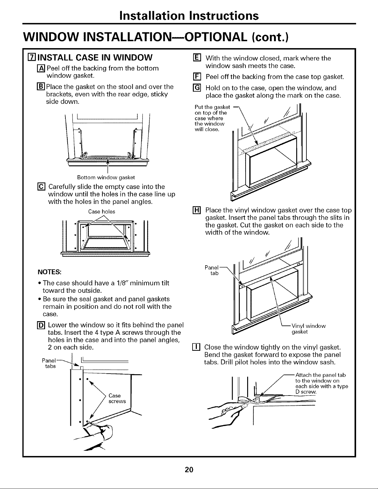
[] INSTALL CASE IN WINDOW
[] Peel off the backing from the bottom
window gasket.
[] Place the gasket on the stool and over the
brackets, even with the rear edge, sticky
side down.
L ]
Bottom window gasket
[] Carefully slide the empty case into the
window until the holes in the case line up
with the holes in the panel angles.
Case holes
!l I!
NOTES:
• The case should have a 1/8" minimum tilt
toward the outside.
• Be sure the seal gasket and panel gaskets
remain in position and do not roll with the
case.
[] Lower the window so it fits behind the panel
tabs. Insert the 4 type A screws through the
holes in the case and into the panel angles,
2 on each side.
ta bs
Case
screws
[] With the window closed, mark where the
window sash meets the case.
[] Peel offthe backing from the case top gasket.
[] Hold on to the case, open the window, and
place the gasket along the mark on the case.
Put the gasket
on top of the
case where
the window
will close.
[] Place the vinyl window gasket over the case top
gasket. Insert the panel tabs through the slits in
the gasket. Cut the gasket on each side to the
width of the window.
[] Close the window tightly on the vinyl gasket.
Bend the gasket forward to expose the panel
tabs. Drill pilot holes into the window sash,
_Attach the panel tab
to the window on
each side with a type
D screw.
2O
Installation Instructions
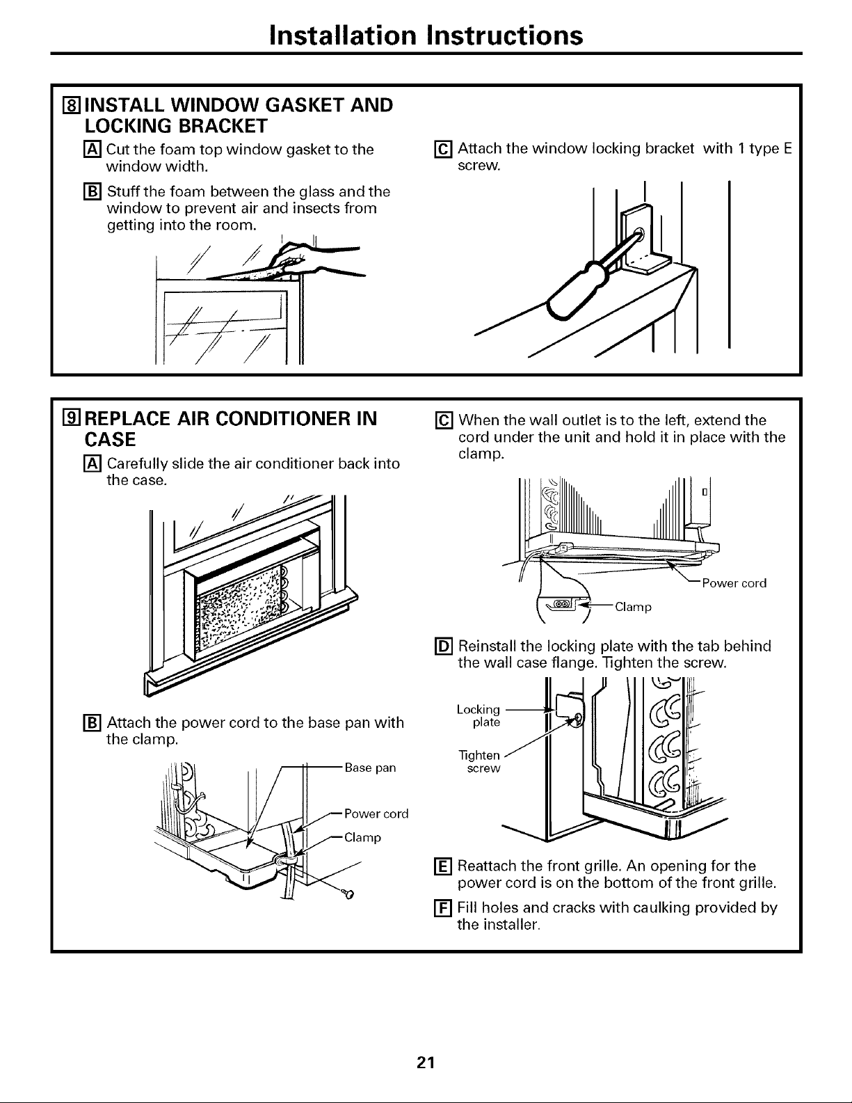
[] INSTALL WINDOW GASKET AND
LOCKING BRACKET
[] Cut the foam top window gasket to the
window width.
[] Stuff the foam between the glass and the
window to prevent air and insects from
getting into the room.
[] Attach the window locking bracket with 1 type E
screw.
I
[] REPLACE AIR CONDITIONER IN
CASE
[] Carefully slide the air conditioner back into
the case.
[] When the wall outlet is to the left, extend the
cord under the unit and hold it in place with the
clamp.
f/
Power cord
p
[] Reinstall the locking plate with the tab behind
the wall case flange. Tighten the screw.
_1 ,u \ll_'qr_/
Locking _ _ C_ i
[] Attach the power cord to the base pan with plate
the clamp. 1ighten J
pan
[] Reattach the front grille. An opening for the
power cord is on the bottom of the front grille.
[] Fill holes and cracks with caulking provided by
the installer.
21
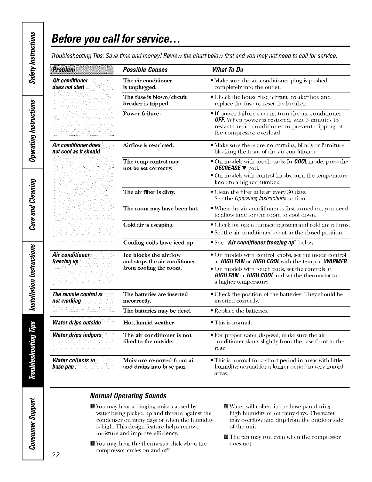
Before youcall forservice...
Troubleshooting -tips:Save time and money! Review the chart below first and you may not need to call for service.
Possible Causes What ToDo
Air conditioner
doesnotstart
• Make sure tile air conditioner I)lug, is pushed
c()ml)letely into the outlet.
The air conditioner
is unplugged,
The fuse is blown/drcuit • Check tile house fltse/ch'cuit breaker be× and
breaker is tripped, replace the fl/se or reset the breakel;
Power failure. •/f power tailure occurs, turn the air conditioner
OFF,_(4'heu l/ower is restored, wait 3 minutes to
restart tile air conditioner to l/reveut tril/l/ing of
the Ci)llll)Yessol" overload.
Air conditioner does Airflow is reslricted. • Make sure there are no curtains, blinds or flu'uitm'e
not cool as it should blocking the fi'ont ot the air coudifioue_;
The temp control may • On models with touch pads: In COOL mode, llress the
not be set correctly. DECREASE• pad.
• On models with control knobs, tm'u tile teml/eratm'e
knob to a higher uumbe_:
The air filter is dirty. • Clean tile filter at least eve_ T 30 da):s.
See the OperatingInstructionssection.
The room may have been hot. • When the air conditioner is filet turned on, you need
to allow time fiw the room to cool down.
Cold air is escaping, " Check fiw open fiu'uace l"egistel_ and cold air returus.
• Set tile air conditioner's vent to tile dosed position.
Cooling coils have iced up. • See "Air conditioner freezing up"below,
Air conditioner
freezingup
Ice blocks the airflow
mad stops the adz"conditioner
from cooling the room.
• On models with control knobs, set tile mode control
at HIGHFANor HIGHCOOLwith the temp at WARMER.
• On models with touch pads, set tile controls at
HIGH FAN or HIGH COOLand set tile themlostat to
a higher temperatm'e.
The remote controlis The batteries are inserted • Check tile position i)f tile batteries. They shl)uld be
not working incorrectly, inserted c(m'ecflv,
The batteries may be dead. • Rel/lace tile batteries.
Water drips outside Hot, humid weather. • This is nl)m, al.
Water drips indoors The air conditioner is not • For l)rl)per water disposal, make sure tile air
tilted to the outside, cl>udifi(>ner slams slightly fl'l)m tile case fl'lmt tl) tile
l'e;ll;
Water collects in Moisture removed from air • This is uom_al fi)r a shl)rt l/efiod in areas with little
basepan mid drains hlto base pan, humidiD"; uom_al fiw a longer l/elJl)d ill very humid
;ll'e;is,
Normal Operating Sounds
[] Ybu may hear a pinging noise caused by
water being picked up and thrl)wn against tile
clmdenser im rainy da)s or when tile humidity
is high, This design teature helps relnove
ml)istm'e and improve eflidency.
[] XM_ter will collect in tile base pan during
high humidi_i or on rainy days. Tile water
may overfll)w and drip fl'om tile outdl)l)r side
of the refit.
[] Tile tilll I11_1_ I'[In e'_en when tile cl)ulI)I'essl)I"
does nl)t.
[] You may hear tile them/ostat click when tile
22 compressor cycles im and i)tE
 Loading...