


 Loading...
<![endif]>Air Conditioners
<![if ! IE]><![endif]>Room
www.GEAppliances.com
Safety Instructions . . . . . . . .2, 3
Operating Instructions
Control Knob Models . . . . . .6, 7
Touch Pad Models . . . . . . . . .4, 5
Care and Cleaning
Air Filter . . . . . . . . . . . . . . . . . .8
Grille and Case . . . . . . . . . . . . .8
Outdoor Coils . . . . . . . . . . . . . .8
Installation Instructions
Through-the-Wall
Installation—Optional . . . . . . .18
Window Installation . . . . . . .9–17
Troubleshooting Tips . . . .19, 20
Normal Operating Sounds . . .20
Consumer Support
Consumer Support . . . . . . . . .24
Product Registration . . . . .21, 22
Warranty . . . . . . . . . . . . . . . . .23
Write the model and serial numbers here:
Model # __________________________
Serial # __________________________
Find these numbers on a label on the side of the air conditioner.
Owner’s Manual and
Installation Instructions
AKL08
AKN08
AKQ08
AKV08
AKW08
49-7453-1 12-02 JR
<![endif]>Consumer Support Troubleshooting Tips Installation Instructions Operating Instructions Safety Instructions
IMPORTANT SAFETY INFORMATION.
READ ALL INSTRUCTIONS BEFORE USING.
 WARNING!
For your safety, the information in this manual must be followed to minimize the risk of fire, electric shock or personal injury.
 SAFETY PRECAUTIONS
 ■ Use this appliance only for its intended purpose as described in this Owner’s Manual.
■This air conditioner must be properly installed in accordance with the Installation Instructions before it is used.
■Never unplug your air conditioner by pulling on the power cord. Always grip plug firmly and pull straight out from the receptacle.
■Repair or replace immediately all electric service cords that have become frayed or otherwise damaged. Do not use a cord that shows cracks or abrasion damage along its length or at either the plug or connector end.
■Turn the mode control to OFF and unplug your air conditioner before making any repairs or cleaning.
■NOTE: We strongly recommend that any servicing be performed by a qualified individual.
■For your safety…do not store or use combustible materials, gasoline or other flammable vapors or liquids in the vicinity of this or any other appliance.
■All air conditioners contain refrigerants, which under federal law must be removed prior to product disposal. If you are getting rid of an old product with refrigerants, check with the company handling disposal about what to do.
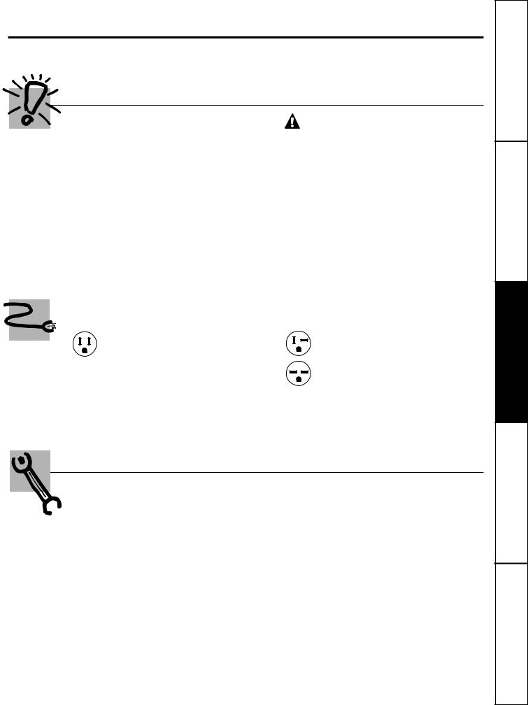
HOW TO CONNECT ELECTRICITY
Do not, under any circumstances, cut or remove the third (ground) prong from the power cord. For personal safety, this appliance must be properly grounded.
The power cord of this appliance is equipped with a 3-prong (grounding) plug which mates with a standard 3-prong (grounding) wall outlet to minimize the possibility of electric shock hazard from this appliance.
Have the wall outlet and circuit checked by a qualified electrician to make sure the outlet is properly grounded.
Where a 2-prong wall outlet is encountered,
it is your personal responsibility and obligation to have it replaced with a properly grounded 3-prong wall outlet.
The air conditioner should always be plugged into its own individual electrical outlet which has a voltage rating that matches the rating plate.
This provides the best performance and also prevents overloading house wiring circuits which could cause a fire hazard from overheated wires.
See the Installation Instructions, Electrical Requirements section for specific electrical connection requirements.
2
www.GEAppliances.com
 WARNING!
USE OF EXTENSION CORDS—115-Volt models only
Because of potential safety hazards under certain conditions, we strongly recommend against the use of an extension cord.
However, if you must use an extension cord, it is absolutely necessary that it be a UL-listed, 14 gauge, 3-wire grounding type appliance extension cord having a grounding type plug and outlet and that the electrical rating of the
cord be 15 amperes (minimum) and 125 volts.
 CAUTION:
DO NOT use an extension cord with any of the 230/208 volt models.
USE OF ADAPTER PLUGS—115-Volt models only
Because of potential safety hazards under certain conditions, we strongly recommend against the use of an adapter plug.
However, if you must use an adapter, where local codes permit, a temporary connection may be made to a properly grounded 2-prong wall outlet by use of a UL-listed adapter available at most local hardware stores.
The larger slot in the adapter must be aligned with the larger slot in the wall outlet to provide proper polarity in the connection of the power cord.
When disconnecting the power cord from the adapter, always hold the adapter in place with one hand while pulling the power cord plug with the other hand. If this is not done, the adapter ground terminal is very likely to break with repeated use.
If the adapter ground terminal breaks, DO NOT USE the air conditioner until a proper ground has been established.
Attaching the adapter ground terminal to a wall outlet cover screw does not ground the appliance unless the cover screw is metal, and not insulated, and the wall outlet is grounded through the house wiring. You should have the circuit checked by a qualified electrician to make sure the outlet is properly grounded.
READ AND FOLLOW THIS SAFETY INFORMATION CAREFULLY.
SAVE THESE INSTRUCTIONS
3
<![endif]>Support Consumer Tips Troubleshooting Instructions Installation Instructions Operating Instructions Safety
<![endif]>Consumer Support Troubleshooting Tips Installation Instructions Operating Instructions Safety Instructions
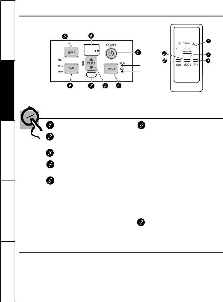
About the controls on the air conditioner—models with touch pads.
Features and appearance will vary.
High fan on 
Cool on
Medium fan on 
Fan on
Low fan on 
Air Conditioner Controls |
Remote Control |
Controls
ON/OFF Pad
Turns air conditioner on and off.
MODE
Use to set the air conditioner to COOL or FAN mode.
Increase ▲ /Decrease ▼ Pads
Use to set temperature when in COOL mode.
FAN Pad
Use to set the fan speed to LOW, MED or HIGH.
TIMER Pad
ON—When the air conditioner is off, it can be set to automatically turn on in
1 to 12 hours at its previous setting. Each touch will set the timer in hours.
OFF—When the air conditioner is on, it can be set to automatically turn off in
1 to 12 hours. Each touch will set the timer in hours.
To cancel the timer, press the TIMER pad until the display time disappears.
NOTE: All timer settings are automatically cancelled if the unit is turned on or off after setting the timer.
Display
Shows the room temperature, set temperature or the time remaining on the timer. After setting the controls, the display will change to show the room temperature.
To recall the set temperature to the display, press the Increase ▲ / Decrease ▼ pad once.
To recall the time remaining on the timer, if it was set, press the TIMER pad once.
Display Codes
E1—Automatic filter clean reminder.
Turn the air conditioner OFF and unplug it.
NOTE: The air conditioner must be unplugged for the automatic filter clean timer to reset. Clean the filter. See the Care and Cleaning section. After cleaning, replace the filter
and plug the air conditioner back in.
Er—Room temperature sensor failure. Call for service.
Remote Control Signal Receiver
Remote Control
■To ensure proper operation, aim the remote control at the signal receiver on the air conditioner.
■The remote control signal has a range of up to 21 feet.
■Make sure nothing is between the air conditioner and the remote control that could block the signal.
■Make sure batteries are fresh and installed correctly as indicated on the remote control.
4
|
www.GEAppliances.com |
When the air conditioner is turned on, it will |
Lights in the display or beside the touch pads |
automatically start in the setting last used, |
on the air conditioner control panel indicate the |
except the timer will be cancelled if it was set. |
selected settings. |
COOL Mode
Use the COOL mode with HIGH, MED or LOW fan for cooling. Use the Increase ▲ / Decrease ▼ pads to set the desired temperature between 60°F and 90°F in 2°F increments (or between 16°C and 31°C in 1°C increments if the control has been set to use Celsius).
A thermostat is used to maintain the room temperature. The compressor will cycle on and off to keep the room at the set level of comfort. Set the thermostat at a lower number and the indoor air will become cooler. Set the thermostat at a higher number and the indoor air will become warmer.
NOTE: If the air conditioner is off and is then turned on while set to COOL, it will take approximately 3 minutes for the compressor to start and cooling to begin.
Cooling Descriptions
For Normal Cooling—Select the COOL mode and
HIGH or MED fan with a middle set temperature.
For Maximum Cooling—Select the COOL mode and HIGH fan with a lower set temperature.
For Quieter & Nighttime Cooling—Select the
COOL mode and LOW fan with a middle set temperature.
NOTE: If you switch from a COOL setting to OFF or to
a fan setting, wait at least 3 minutes before switching back to a COOL setting.
FAN Mode
Use the FAN at HIGH, MED or LOW to provide air circulation and filtering without cooling. Since fan only settings do not provide cooling, a temperature setting will not be displayed.
Fahrenheit or Celsius
Your control is set to use and display Fahrenheit temperature selections, but you may change it to use and display Celsius selections.
Press and hold the Increase ▲ / Decrease ▼ pads at the same time to switch to ˚C or ˚F as desired.
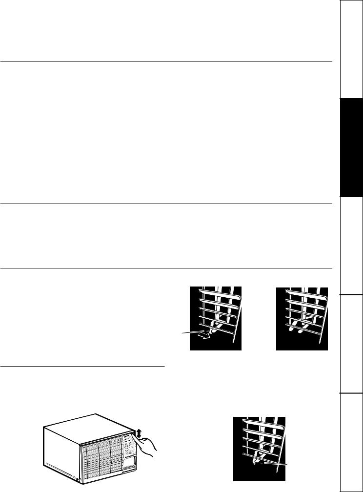
Vent Control
The vent control is located on the inside of the air louvers at the bottom of the vent.
When set at CLOSE, only the air inside the room will be circulated and conditioned. When set at OPEN, some inside air is exhausted outside.
Vent control lever
Vent control lever
lever 
To open the vent. |
To close the vent. |
Air Direction
Up and Down |
Side-to-Side |
Fingertip pressure on the horizontal louvers |
The side-to-side air direction is adjusted by moving |
adjusts the air direction up or down. |
the air direction lever to the left or right. |
Air direction lever
5
<![endif]>Support Consumer Tips Troubleshooting Instructions Installation Instructions Operating Instructions Safety
<![endif]>Consumer Support Troubleshooting Tips Installation Instructions Operating Instructions Safety Instructions
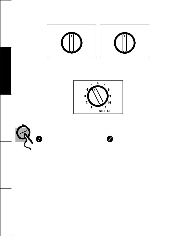
About the controls on the air conditioner—models with control knobs.
Features and appearance will vary.
OFF |
|
|
OFF |
HIGH |
HIGH |
COOL |
FAN |
COOL |
FAN |
||
MED |
LOW |
|
|
COOL |
FAN |
|
|
LOW |
|
|
|
COOL |
|
|
|
 MODE CONTROLS
Your model will have one of the above type controls.
 TEMP CONTROL
Controls
Mode Controls
HIGH COOL, MED COOL and LOW COOL provide cooling with different fan speeds.
COOL provides cooling with a fixed fan speed.
LOW FAN, HIGH FAN or FAN provides air circulation and filtering without cooling.
NOTE: If you move the switch from a cool setting to OFF or to a fan setting, wait at least 3 minutes before switching back to a cool setting.
Cooling Descriptions
For Normal Cooling—Select HIGH COOL or
MED COOL with the temp control at midpoint.
For Maximum Cooling—Select HIGH COOL with the temp control at the highest number available on your knob.
For Quieter and Nighttime Cooling—Select
LOW COOL with the temp control at midpoint.
Temp Controls
The temp control is used to maintain the room temperature. The compressor will cycle on and off to keep the room at the same level of comfort. When you turn the knob to a higher number, the indoor air will become cooler. Turn the knob to a lower number and the indoor air will become warmer.
6
www.GEAppliances.com
Additional controls and important information.
Vent Control
The vent control is located on the inside of the air louvers at the bottom of the vent.
When set at CLOSE, only the air inside the room will be circulated and conditioned. When set
at OPEN, some inside air is exhausted
outside. 
 Vent control lever
To open the vent. |
To close the vent. |
Air Direction—Up and Down
Fingertip pressure on the horizontal louvers adjusts the air direction up or down.
Air Direction—Side-to-Side
The side-to-side air direction is adjusted by moving the air direction lever to the left or right.
Air direction lever
7
<![endif]>Support Consumer Tips Troubleshooting Instructions Installation Instructions Operating Instructions Safety
<![endif]>Consumer Support Troubleshooting Tips Installation Instructions Operating Instructions Safety Instructions
Care and cleaning of the air conditioner.
Grille and Case
Turn the air conditioner off and remove the plug |
To clean, use water and a mild detergent. Do not |
from the wall outlet before cleaning. |
use bleach or abrasives. |
Outdoor Coils
The coils on the outdoor side of the air conditioner should be checked regularly. If they are clogged with dirt or soot, they may be professionally steam cleaned, a service available through your GE service outlet.
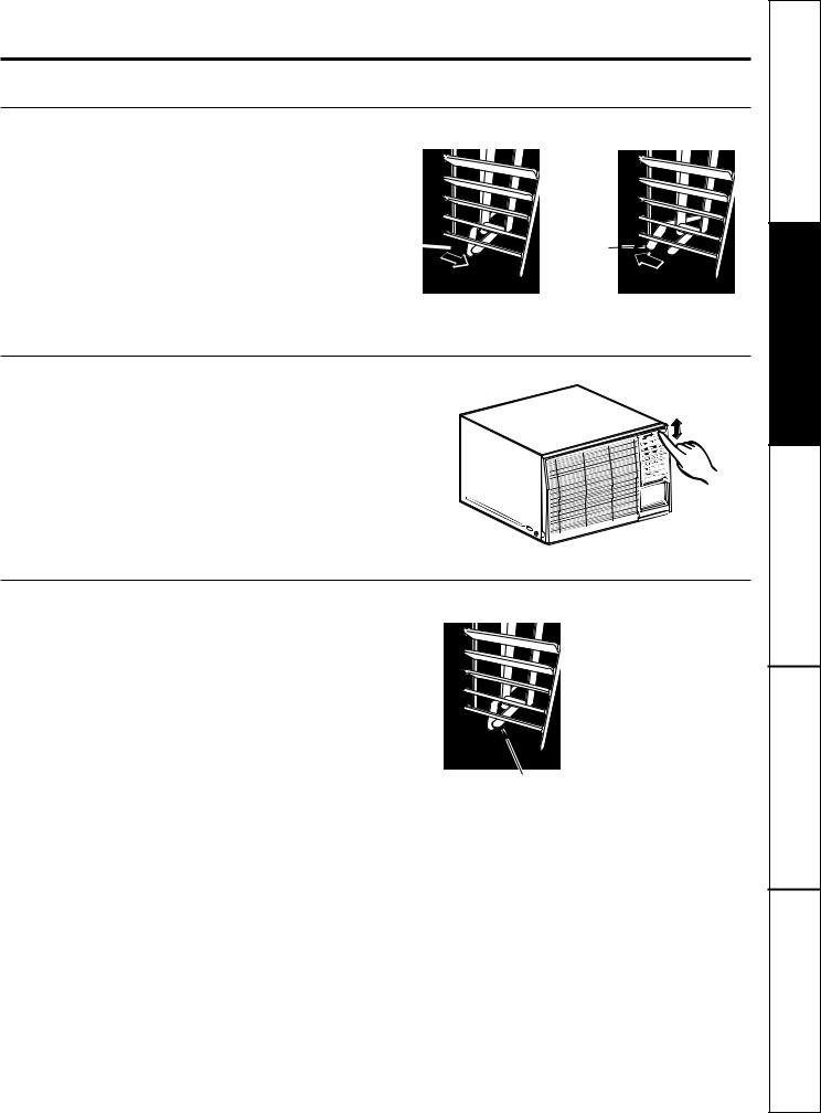
Air Filter
The air filter behind the front grille should be checked and cleaned at least every 30 days or more often if necessary.
E1 in the display (on models with touch pads) is an automatic filter clean reminder. Turn the air conditioner OFF and unplug it.
NOTE: The air conditioner must be unplugged for the automatic filter clean timer to reset.
Clean the filter with warm, soapy water. Rinse and let the filter dry before replacing it.
NOTE: DO NOT rinse, or put the filter in an automatic dishwasher.
 CAUTION: DO NOT operate the air conditioner without a filter because dirt and lint will clog it and reduce performance.
To remove:
1 |
Pull to unlatch the lower corners of the inlet |
|
grille and lift it up and off. |
||
|
2 |
Using the tab, pull up slightly on the filter to |
release it and pull it down to remove. |
8
Preparing to install the air conditioner.
Read these instructions completely and carefully.
Before You Begin
NOTE TO INSTALLER: Leave these instructions with |
CAUTION: |
|
the air conditioner after installation is completed. |
||
NOTE TO CONSUMER: Keep this Owner’s Manual |
Do not, under any circumstances, cut or remove |
|
and Installation Instructions for future use. |
the third (ground) prong from the power cord. |
|
IMPORTANT NOTES: |
Do not change the plug on the power cord of this |
|
For personal safety, this air conditioner must be |
air conditioner. |
|
Aluminum house wiring may present special |
||
properly grounded. |
||
It is important to have the wall outlet and circuit |
problems—consult a qualified electrician. |
|
|
||
checked by a qualified electrician if there is any |
|
|
doubt as to whether a proper ground exists. |
|
|
Follow National Electrical Codes (NEC) and/or local |
|
|
codes and ordinances. |
|
|
Electrical Requirements |
|
Some models require 115/120-volt a.c., 60 Hz grounded outlet protected with a 15-amp time delay fuse or circuit breaker.
The 3-prong grounding plug minimizes the possibility of electric shock hazard. If the wall outlet you plan to use is only a 2-prong outlet, it is your responsibility to have it replaced with a properly grounded 3-prong wall outlet.
Some models require 230/208-volt a.c., protected with a time delay fuse or circuit breaker. These models should be installed on their own single branch circuit for best performance and to prevent overloading house or apartment wiring circuits, which could cause a possible fire hazard from overheating wires.
Tools You Will Need
■ Phillips-head screwdriver |
■ Scissors or knife |
■ Adjustable wrench |
■ Pencil |
■ Ruler or tape measure |
■ Level |
■ Drill |
|
9
<![endif]>Support Consumer Tips Troubleshooting Instructions Installation Instructions Operating Instructions Safety

<![endif]>Consumer Support Troubleshooting Tips Installation Instructions Operating Instructions Safety Instructions
Window installation instructions.
Parts Included
Window sash seal  (thin, adhesive-backed)
Left |
Foam top |
|
accordion |
||
window gasket |
||
panel |
||
|
||
|
Top mounting rail |
|
|
seal strip |
 Air conditioner case
Bottom |
Right |
|
accordion |
||
mounting rail |
||
panel |
||
|
||
Support rail (2) |
Top mounting rail |
|
|
||
Support bracket (2) |
Window stool |
|
seal (thick, |
||
Nut (2) |
adhesive-backed) |

 Leveling bolt (2)
Type A (17) |
Type B (11) |
Type C (6) |
Accordion panel |
Window locking |
|
|
|
clamp (2) |
bracket |
10
Read completely, then follow step-by-step.
1 |
Window Requirements |
■ These instructions are for a standard double- |
|
hung window. You will need to modify them for |
other types of windows.
■ The air conditioner can be installed without the accordion panels if needed to fit in a narrow window. See the window opening dimensions.
■ All supporting parts must be secured to firm wood, masonry or metal.
■ The electrical outlet must be within reach of the power cord.
15″ min.
21-3/4″ to 35-1/4″ (With accordion panels)
18″ min. (Without accordion panels)
2 |
|
Storm Window Requirements |
||||||||||||||||
|
A storm window frame will not allow the air |
|||||||||||||||||
|
conditioner to tilt towards the outside and |
|||||||||||||||||
|
||||||||||||||||||
|
|
will keep it from draining properly. To adjust |
||||||||||||||||
|
|
for this, attach a piece of wood to the stool. |
||||||||||||||||
|
|
|
|
|
|
|
|
|
|
|
|
|
|
|
|
|
|
|
|
|
|
|
|
|
|
|
|
|
|
|
|
|
|
|
|
Wood |
|
|
|
|
|
|
|
|
|
|
|
|
|
|
|
|
|
|
|
|
|
|
|
|
|
|
|
|
|
|
|
|
|
|
|
|
|
|
|
|
|
1/2″ higher |
|
|
|
|
|
|
|
|
|
|
|
|
|
|
||
|
|
|
|
|
|
|
||||||||||||
|
|
than frame |
|
|
|
|
|
|
|
|
|
|
|
|
|
|
||
|
|
|
|
|
|
|
|
|
|
|
|
|
Stool |
|
||||
|
|
|
|
|
|
|
|
|
|
|
|
|
|
|
|
|
|
|
|
|
|
|
|
|
|
|
|
|
|||||||||
|
|
Storm window |
|
|
|
|||||||||||||
|
|
frame |
|
|
|
|
|
|
|
|
|
|||||||
|
|
|
|
|
||||||||||||||
|
|
|
|
|
|
|
|
|
|
|
|
|
|
|
|
|
|
|
|
|
|
|
|
|
|
|
|
|
|
|
|
|
|
|
|
|
|
WOOD PIECES—
WIDTH: 2″
LENGTH: Long enough to fit inside the window frame.
THICKNESS: To determine the thickness, place a piece of wood on the stool to make it 1/2″ higher than the top of the storm window frame.
Attach securely with nails or screws provided by the installer.
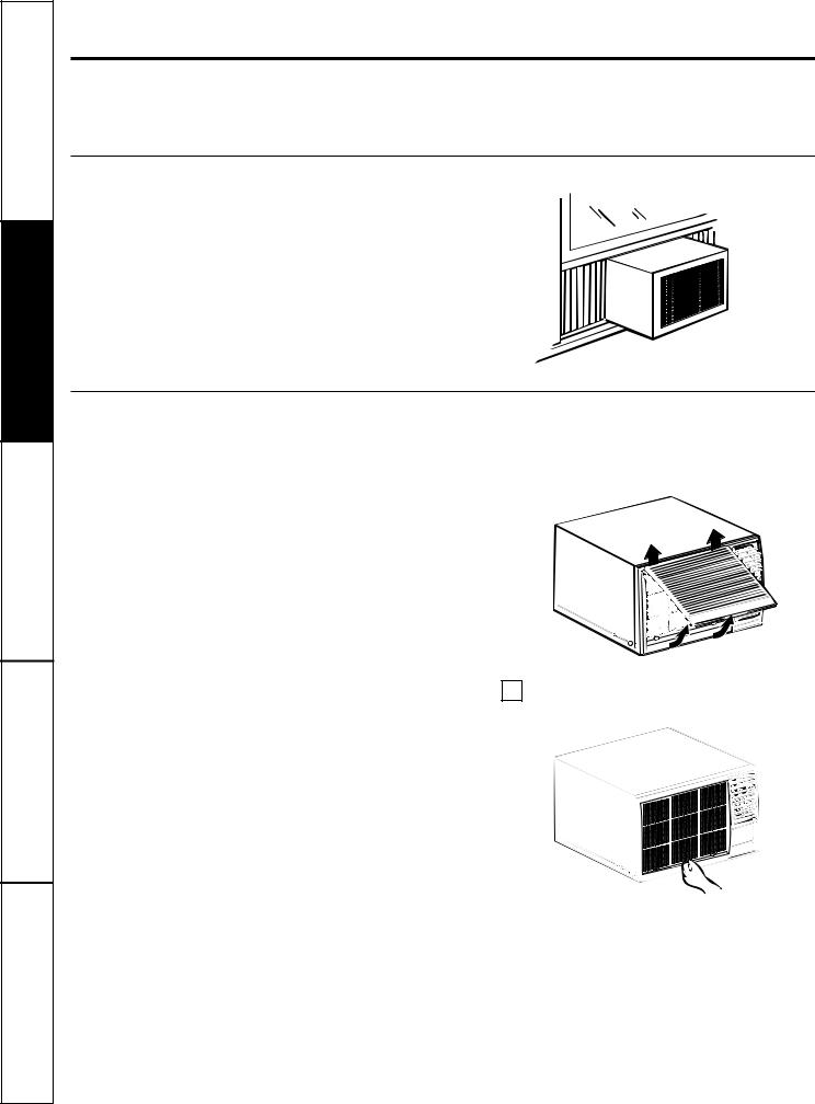
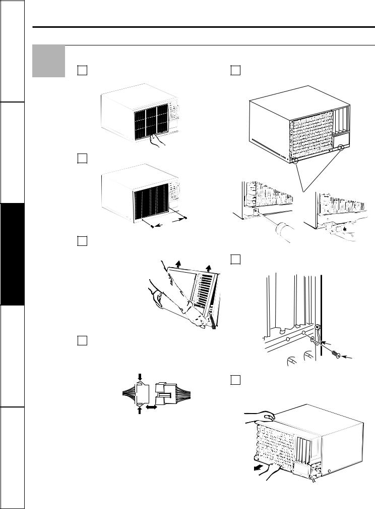
Remove the Air Conditioner From the Case
3 |
|
Remove and discard the 2 shipping screws |
|
Pull to unlatch the lower corners of the inlet |
|
A |
B |
||||
from the bottom rear of the case. |
grille and lift it up and off. |
||||
|
|
11
<![endif]>Support Consumer Tips Troubleshooting Instructions Installation Instructions Operating Instructions Safety
<![endif]>Consumer Support Troubleshooting Tips Installation Instructions Operating Instructions Safety Instructions
Window installation instructions.
Remove the Air Conditioner From the Case (cont.)
3 |
C |
Using the tab, pull up slightly on the filter |
G |
Remove the two locking screws and locking |
to release it and pull it down to remove. |
brackets from the lower front of the unit. |
D Remove the two grille frame screws.
|
Grille frame screws |
|
E |
Grasp the lower corners of the grille frame |
|
|
while pressing in on the case sides with your |
|
|
finger tips. Pull out to release and lift it up. |
Remove the screw securing the ground wire |
|
H |
|
|
NOTE: Do not pull the |
to the right side face of the unit. |
|
bottom edge toward |
|
|
you more than 3 ″ or |
|
|
you may damage the |
|
|
tabs of the grille. |
|
F |
On some models, you must also disconnect |
Ground wire |
|
the control connectors before the grille frame |
|
|
can be removed. Press the locking tabs in |
Screw |
|
while pulling on the other side to release. |
|
|
|
|
|
Press in |
Slide the air conditioner from the case by |
|
I |
|
|
|
gripping the base pan handle and pulling |
|
|
forward while bracing the case. |
|
Pull |
|
|
Press in |
|
12
4
5
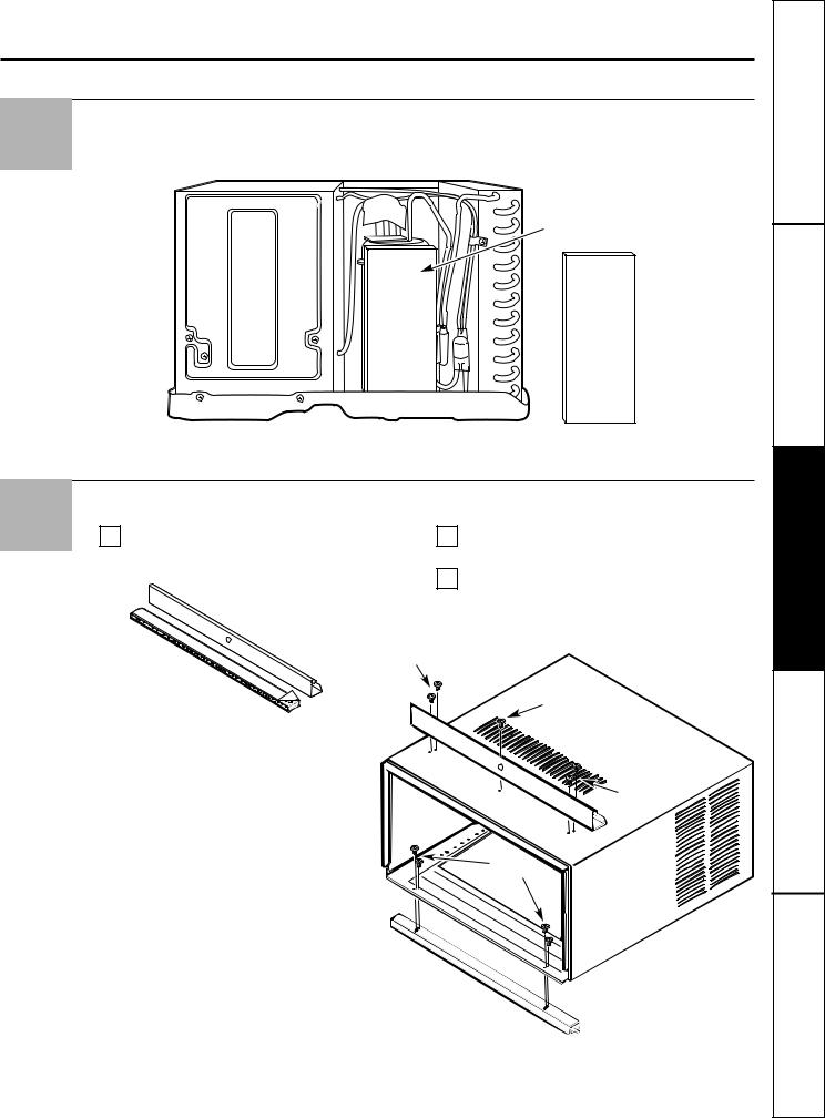
Remove the Shipping Pad
Remove and discard the shipping pad next to the compressor.
Remove and discard shipping pad
Install the Mounting Rails onto the Case
ARemove the backing from the top mounting rail seal strip and attach it to the bottom of the top mounting rail.
B
C
Attach the top mounting rail onto the top of the case with 5 Type A screws.
Attach the bottom mounting rail to the bottom of the case from the inside, using 4 Type A screws.
Type A screws
Type A screw
A screws |
Type A |
screws |
13
<![endif]>Support Consumer Tips Troubleshooting Instructions Installation Instructions Operating Instructions Safety

<![endif]>Consumer Support Troubleshooting Tips Installation Instructions Operating Instructions Safety Instructions
Window installation instructions.
Install the Side Accordion Panels
6 |
A |
Slide the left and right accordion panels into |
B |
Attach the accordion panels to the case using |
|
the top and bottom mounting rails. |
4 Type A screws on each side. |
||||
|
|
 Top mounting rail
Accordion panel
Type A screws 
Bottom mounting rail
Prepare the Window
7 |
A |
Cut the window sash seal (thin, adhesive- |
B |
Mark the centerline of the stool. Measure and |
|
backed) to the window width and stick the |
|
mark the locations for the support assemblies |
|
|
|
|||
|
adhesive side to the bottom of the sash. |
|
81⁄8″ from both sides of the centerline. |
Window sash seal 
Stool
81⁄8″
81⁄8″
14

8
9
Assemble the Supports
ALoosely attach a support bracket to a support rail using 2 Type C screws.
Type C screws

 Support rail
 Support bracket
NOTE: The support bracket may be attached into either slot in the support rail, depending on the depth of your window sill.
BThread a nut onto a leveling bolt, then thread the leveling bolt into the support bracket. An adjustable wrench may be needed.

 Support bracket

 Nut
Nut

 Leveling bolt
CBefore attaching the support, hold the neck of the support rail against the back edge of the window stool.
Stool
Adjust as Neck of 
 needed support rail
DAdjust the position of the support bracket inward or outward on the support rail until the leveling bolt is near the outside edge of the sill.
NOTE: Make sure that the leveling bolt will be firmly supported by the sill.
ETighten the Type C screws to secure the support bracket to the support rail in the correct position.
FRepeat steps A–E to assemble the second support.
Install the Supports
ALine up the V-notches in the support rails with the left and right marks on the stool. Make
sure that the support rail is against the back of the stool and drill two 1/8″ pilot holes into the stool through the holes in the head of the support rail. Attach the supports to the stool using two Type B screws in each support.
Sill
Stool |
Supports |
|
Type B screws
BAdjust the leveling bolts against the sill so that the supports have a slight tilt to the outside. Use a level; about 1/2 bubble will be the correct slant to the outside. After leveling is done, tighten the leveling bolt nut.
1/2 bubble

 Nut
Nut
 Leveling bolt
NOTE: Use a steel washer between the leveling bolts and the sill if the sill is weak.
CAttach the adhesive side of the window stool seal (thick, adhesive-backed) to the window stool.
Window stool seal 
15
<![endif]>Support Consumer Tips Troubleshooting Instructions Installation Instructions Operating Instructions Safety
Loading...