


GE AJCQ06LWH, AJCQ08AWH, AJCQ10AWH, AJCQ10DWH, AJCQ12AWH Owner’s Manual & Installation Instructions
...<![endif]>26” Built-In Wi-Fi AIR CONDITIONER
SAFETY INFORMATION . . . . . . . . .3
USING THE AIR
CONDITIONER . . . . . . . . . . . . . . 4
WI-FI SETUP . . . . . . . . . . . . . . . . . . . . . .7
CARE AND CLEANING . . . . . . . . . . .9
INSTALLATION
INSTRUCTIONS. . . . . . . . . . . . . . 10
TROUBLESHOOTING TIPS. . . . . . 12
CONSUMER SUPPORT
Warranty . . . . . . . . . . . . . . . . . . . . . . . . . . . . 15
Consumer Support . . . . . . . . . . . . . . . . . . . . 16
OWNER’S MANUAL &
INSTALLATION
INSTRUCTIONS
Cool Only Models
AJCQ06LWH
AJCQ08AWH
AJCQ10AWH
AJCQ10DWH
AJCQ12AWH
AJCQ12DWH
AJCQ14DWH
Cool Only High Mount Models
AJCM08AWH
AJCM10AWH
AJCM10DWH
AJCM12DWH
Heat/Cool Models
AJEQ08AWH
AJEQ10DWH
AJEQ12DWH
AJEQ14DWH
Heat/Cool High Mount Models
AJEM12DWH
Heatpump Models
AJHQ08AWH
AJHQ12DWH
Write the model and serial numbers here:
Model #_________________
Serial # _________________
You can find the this information on a label attached to the right side of the chassis.
ESPAÑOL
For a Spanish version of this manual, visit our Website at GEAppliances.com.
Para consultar una version en español de este manual de instrucciones, visite nuestro sitio de internet GEAppliances.com.
FRANÇAIS
For a French version of this manual, visit our Website at GEAppliances.ca.
Pour un version français de ce manuel d’utilisation, veuillez visiter notre site web à l’adresse GEAppliances.ca.
GE is a trademark of the General Electric Company. Manufactured under trademark license.
49-5000492 Rev. 4 02-21 GEA

THANK YOU FOR MAKING GE APPLIANCES A PART OF YOUR HOME.
Whether you grew up with GE Appliances, or this is your first, we’re happy to have you in the family.
We take pride in the craftsmanship, innovation and design that goes into every GE Appliances product, and we think you will too. Among other things, registration of your appliance ensures that we can deliver important product information and warranty details when you need them.
Register your GE appliance now online. Helpful websites and phone numbers are available in the Consumer Support section of this Owner’s Manual. You may also mail in the pre-printed registration card included in the packing material.
2 |
|
49-5000492 Rev. 4 |
|

IMPORTANT SAFETY INFORMATION
READ ALL INSTRUCTIONS BEFORE USING THE APPLIANCE
For your safety, the information in this manual must be followed to minimize the risk of  WARNING fire, electric shock or personal injury.
Ŷ 8VH WKLV DSSOLDQFH RQO\ IRU LWV LQWHQGHG SXUSRVH DV described in this Owner’s Manual.
Ŷ This air conditioner must be properly installed in accordance with the Installation Instructions before it is used.
Ŷ Never unplug your air conditioner by pulling on the power cord. Always grip plug firmly and pull straight out from the receptacle.
Ŷ Replace immediately all electric service cords that have become frayed or otherwise damaged. A damaged power supply cord must be replaced with a new power supply cord obtained from the manufacturer and not repaired. Do not use a cord that shows cracks or abrasion damage along its length or at either the plug or connector end.
Ŷ Turn the unit OFF and unplug your air conditioner before cleaning.
Ŷ For your safety…do not store or use combustible materials, gasoline or other flammable vapors or liquids in the vicinity of this or any other appliance.
Ŷ If the receptacle does not match the plug, the receptacle must be changed out by a qualified electrician.

 WARNING USE OF EXTENSION CORDS
RISK OF FIRE. Could cause serious injury or death. |
Ŷ '2 127 XVH VXUJH SURWHFWRUV RU PXOWL RXWOHW |
Ŷ '2 127 XVH DQ H[WHQVLRQ FRUG ZLWK WKLV air |
adaptors with this air conditioner. |
|
|
conditioner. |
|
HOW TO CONNECT ELECTRICITY
Do not, under any circumstances, cut or remove the third (ground) prong from the power cord. For personal safety, this appliance must be properly grounded.
DO NOT use an adapter plug with this appliance.
The power cord of this appliance is equipped with a 3-prong (grounding) plug which mates with a standard 3-prong (grounding) wall outlet to minimize the possibility of electric shock hazard from this appliance.
Power cord includes a current interrupter device. A test and reset button is provided on the plug case. The device should be tested on a periodic basis by first pressing the TEST button and then the RESET button while plugged into the outlet. If the TEST button does not trip or if the RESET button will not stay engaged, discontinue use of the air conditioner and contact a qualified service technician.
Have the wall outlet and circuit checked by a qualified electrician to make sure the outlet is properly grounded.
Where a 2-prong wall outlet is encountered, it is your personal responsibility and obligation to have it replaced with a properly grounded 3-prong wall outlet.
The air conditioner should always be plugged into its own individual electrical outlet which has a voltage rating that matches the rating plate.
This provides the best performance and also prevents overloading house wiring circuits which could cause a fire hazard from overheated wires.
See the Installation Instructions, Electrical Requirements section for specific electrical connection requirements.
For appliance recycling information please visit GEAppliances.com/recycling.
<![endif]>INFORMATION SAFETY
READ AND SAVE THESE INSTRUCTIONS
49-5000492 Rev. 4 |
3 |
<![endif]>USING THE AIR CONDITIONER
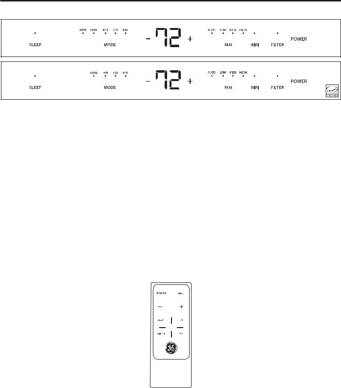
Using the Air Conditioner - Controls
Appearance may vary.
Air Conditioner Controls
•Lights below the touch pads on the control panel indicate
the selected settings
1. POWER
Turns air conditioner on and off.
2. DISPLAY
Displays the temperature setting.
3. MODE
8VH WR VHW HEAT (on some models), COOL, FAN, ECO, or DRY modes. Indicator lights on the controls will show the mode selected.
4. TEMP INCREASE (+) / DECREASE (–) PADS
8VH WR VHW WHPSHUDWXUH ZKHQ LQ +($7 RQ VRPH PRGHOV
COOL, ECO, or DRY modes.
5. FAN SPEED
8VH WR VHW WKH IDQ VSHHG DW AUTO, LOW, MEDIUM, or
HIGH. Indicator lights will show the speed selected.
6. FILTER
Monitors accumulated fan run time as a reminder to clean the filter.
7. WI-FI
This unit is GE Appliances Wi-Fi Connect Enabled.
8. SLEEP
Allows room temperature to increase in Cool mode or decrease in Heat mode during sleeping hours.
Remote Control
ŶTo ensure proper operation, aim the remote control at |
ŶMake sure nothing is between the air conditioner and |
the signal receiver on the air conditioner. |
the remote control that could block the signal. |
ŶThe remote control signal has a range up to 21 feet. |
ŶMake sure the battery is fresh and installed correctly— |
ŶThe remote control will control the unit even if |
see the Care and Cleaning section. |
connected to the Wi-Fi. |
|
4 |
49-5000492 Rev. 4 |

Using the Air Conditioner - Features
To Adjust Fan Speeds
Press the FAN SPEED button to select the FAN SPEED in four steps - AUTO, LOW, MED, or HIGH. Each time the button is pressed, the fan speed mode is shifted.
For some models, the fan speed can not be adjusted under HEAT mode. In DRY mode, the fan speed is controlled at low automatically.
In AUTO, the fan speed will automatically operate at the speed needed to provide optimum comfort. If the room needs faster cooling to meet the set temperature, the fan will automatically increase. If the room needs less cooling, the fan will automatically decrease.
SLEEP
SLEEP set the unit to gradually change setting over an 8 hour period to allow for increased energy savings during sleeping hours. The SLEEP mode is available only in COOL and FAN only settings.
Press the SLEEP mode pad and its light will illuminate. The FAN indicator will stay at the same setting but the air conditioner will automatically change the FAN speed to low in either the COOL or FAN only mode.
In FAN only mode, the fan will stay in the LOW speed setting for 8 hours. After 8 hours, the air conditioner will resume the settings that were in place before the SLEEP mode pad was pressed.
In COOL and HEAT modes, the fan will stay in LOW speed setting for 8 hours from the time the SLEEP mode pad was pressed. The air conditioner will raise the set point 2ºF(1ºC) in cooling (lower the set point in heating) in 30 minutes and 2ºF(1ºC) more in another 30 minutes where it will remain for another 7 hours. After this 8-hour period, the unit will resume the settings that were in place before the SLEEP mode pad was pressed.
While the unit is in SLEEP mode, pressing any pad will return it to the settings that were in place before the SLEEP mode was pressed.
Check Filter
Press the FILTER button to initiate this feature. This |
The LED (light) will illuminate after 250 hours of |
feature is a reminder to clean the air filter for more |
operation. To reset after cleaning the filter, press the |
efficient operation. |
FILTER button and the light will go off. |
To Select the Operating Mode
To choose operating mode, press the MODE button. Each time you press the button, a mode is selected in a sequence that goes from HEAT (on some models),
COOL, FAN, ECO, and DRY only. The indicator light will be illuminated and remain on once the mode is selected.
Models AJHQ08AWH and AJHQ12DWH are Heatpumps and the heating function will automatically switch between electric heat mode and heatpump mode to maintain room set temperature and to reduce operating costs. At outdoor temperatures below 40ºF(4.4ºC),
the unit will operate in electric heat mode only. The AJHQ08AWH is not intended to be the sole source of heat.
To operate in FAN only Mode:
Ŷ 8VH WKLV IXQFWLRQ RQO\ ZKHQ FRROLQJ RU KHDWLQJ RQ VRPH models) is not desired. You can choose any fan speed you prefer.
ŶDuring this function, the display will show the actual
room temperature, not the set temperature in the cooling or heating (on some models) mode.
ŶIn FAN only mode, the temperature is not adjustable.
To operate in ECO Mode:
ŶWith this feature, the unit will operate in COOL mode only. The fan will operate with the compressor to cool the space. The fan will continue to run for 3 minutes after the compressor stops and the room set temperature has been met. The fan then cycles on for 2 minutes at 10 minute intervals until the room temperature is above the set point, at which time the compressor turns on and cooling starts.
To operate in DRY Mode:
ŶIn this mode, the air conditioner will generally operate in the form of a dehumidifer. Since the conditioned space is a closed or sealed area, some degree of cooling
will occur. In DRY mode, the fan operates in LOW fan speed only.
Fahrenheit vs. Celsius
To change the temperature display from Fahrenheit to Celsius, press – and + together and hold for 3 seconds.
Control Panel Lights
This unit has a control panel lights ON/OFF feature that |
SLEEP pad for 3 seconds. The unit will beep to signal a |
|
turns them off when there is no activity for more than |
successful toggle off of this feature. |
|
1 minute. To wake up the lights, press any pad on the |
Pressing the DISPLAY on the wireless remote will turn |
|
controls and the lights will come on to show the previous |
||
the control panel lights off immediately. |
||
settings. To turn this feature off, press and hold the |
||
|
<![endif]>CONDITIONER AIR THE USING
49-5000492 Rev. 4 |
5 |
<![endif]>USING THE AIR CONDITIONER
Using the Air Conditioner - Features
Additional Features
The “Cool” circuit has an automatic 3 minute delayed start if the unit is turned off and on quickly. This prevents
overheating of the compressor and possible circuit breaker tripping. The fan will continue to run during this time.
There is a 2 second delay for the compressor to stop when selecting fan or heat. This is to cover the possibility of
having to roll through to select another mode.
The control will maintain the set temperature within 1°F between 62°F and 86°F in cool or heat mode (on some models).
After a power outage, the unit will remember last setting and return the unit to that setting when power is restore.
Air Direction
Adjustable louvers control air flow direction.
The louvers will allow you to direct the air flow up or down and left or right throughout the room as needed until the desired left/right direction is obtained. Pivot horizontal louvers until the desired up/down direction is obtained.
Ventilation
To open the ventilation port, remove the adjustable air discharge louvers by gently pulling forward the right end until it is released from the pivot point. Shift the louvers to the right to release the left end from its pivot point. To open the ventilation port, pull the lever forward. The lever will lock in place. To replace the air discharge louvers, reverse the above procedure 


Vent Door Open |
Vent Door Closed |
Remote Wall Thermostat (Heat/Cool models only)
All heat/cool models are capable of being controlled by a 24 VAC remote wall thermostat. The thermostat control connection board is located behind a metal cover on the right side of the metal chassis cover. To open the cover, remove the Phillips head screw and lift from the slots at the bottom. To properly connect the wiring from a remote wall thermostat, follow these steps:
1.Order the 8-pin connector from GE Appliances Service. Call 1-800-626-2002 and order WP26X24981. A connector is required for each unit being controlled by a wall thermostat
2.Install the remote thermostat according to the directions included with it.
8VLQJ ZLUH QXWV LQFOXGHG ZLWK WKH SLQ FRQQHFWRU connect the wiring from the wall thermostat per the following; (Proper connection of the wiring is critical. Improper hookups could result in damage to the air conditioner components and may not be covered by the product warranty) After properly making the wire nut connections, wrap the 7 connectors together with electrical tape and push them into the lower right
FRUQHU RI WKH FRQWURO ER[ RSHQLQJ WR NHHS WKHP RXW RI the way. Route the thermostat wiring out the bottom of the opening at the notch and replace the metal cover.
Connector Wire Color Codes |
Thermostat Connections |
Black |
Common |
White |
Electric Heater |
Yellow |
Compressor |
Blue |
B terminal (heatpump models only) |
Green |
Fan High |
Tan |
Fan Low |
Red |
24 VAC |
NOTE: When the thermostat is installed and power is applied, the control display will not illuminate and the unit is automatically controlled by the wall thermostat.
NOTE: When using Wi-Fi, a remote wall thermostat will not function. If a thermostat is installed, Wi-Fi has operation priority.
Do Not Operate the unit in COOL mode when outdoor temperatures are below 64ºF(18ºC).
6 |
49-5000492 Rev. 4 |

WiFi Setup
GE Appliances SmartHQ (for customers in the United States)
GE Appliances SmartHQ Enabled. If your Air Conditioner (AC) has a Connected Appliance Information label located on the outside as shown below, your AC is GE Appliances SmartHQ Enabled. A WiFi communication card is built into the product allowing it to communicate with your smart phone for remote monitoring, control and
notifications. Please visit GEAppliances.com/connect to learn more about connected appliance features, and to learn what connected appliance apps will work with your smart phone.
FCC ID: ZKJ-WCATA006
IC: 10229AWCATA006
Network:
GE_MODULE_XXXX
XXXXXXXX |
Password: |
Network: |
|
GE_MODULE_XXXX |
|
Password: |
XXXXXXXX |
MAC: |
|
XXXXXXXXXXXX |
|
MAC:
XXXXXXXXXXXX
WiFi Connectivity: For assistance with the appliance or the ConnectPlus network connectivity (for models that are WiFi enabled or WiFi optional), please call 1-800-220-6899.
<![endif]>SETUP WIFI
49-5000492 Rev. 4 |
7 |

<![endif]>WIFI SETUP
WiFi Setup
How it Works
Download the GE Appliances App |
8VH WKH DSS WR FRQQHFW \RXU URRP DLU |
Once connected, use the app to turn |
|
conditioner to WiFi |
down your air conditioner as you |
|
|
leave work. |
|
|
CHANGE TEMP |
|
|
TO 65 |
Getting Started
To connect your room air conditioner, you’ll need the GE Appliances SmartHQ App. The app will walk you through the connection process. Download the app from iTunes or Google Play.
All connected appliance data is held in strict accordance with the GE Appliances Connected Data Privacy Policy. Visit geappliances.com/privacy/privacy_policy_ connected to view this policy.
Questions about SmartHQ
Get answers you need about setting up WiFi appliances and connecting to your home network in our support articles.
Visit products.geappliances.com/appliance/gea- support-search-content to view wifi connect room air conditioner support articles.
REGULATORY INFORMATION
•Increase the separation between the equipment and receiver.
FCC/IC Compliance Statement:
This device complies with Part 15 of the FCC Rules. Operation is subject to the following two conditions:
1.This device may not cause harmful interference.
2.This device must accept any interference received, including interference that may cause undesired operation.
This equipment has been tested and found to comply with the limits for a Class B digital device, pursuant to Part 15 of the FCC Rules. These limits are designed to provide reasonable protection against harmful interference in a residential installation. This equipment
generates, uses and can radiate radio frequency energy and, if not installed and used in accordance with the instructions, may cause harmful interference to radio communications. However, there is no guarantee that interference will not occur in a particular installation. If this equipment does cause harmful interference to radio or television reception, which can be determined by turning the equipment off and on, the user is encouraged to try to correct the interference by one or more of the following measures:
•Connect the equipment into an outlet on a circuit different from that to which the receiver is connected.
&RQVXOW WKH GHDOHU RU DQ H[SHULHQFHG UDGLR WHOHYLVLRQ technician for help.
Labelling: Changes or modifications to this unit not
H[SUHVVO\ DSSURYHG E\ WKH PDQXIDFWXUHU FRXOG YRLG WKH user’s authority to operate the equipment.
This product has Wi-Fi capability and requires Internet connectivity and a wireless router to enable interconnection with an Energy Management System,
DQG RU ZLWK RWKHU H[WHUQDO GHYLFHV V\VWHPV RU applications.
8 |
49-5000492 Rev. 4 |

Care and Cleaning
Air filter
To access the filter, grasp the front grille louvers on both sides at the recess and pull forward. Remove the filter by lifting up and out. Note the filter direction when re-installing.
Wash the filter using liquid dishwashing detergent and warm water. Rinse the filter thoroughly. Gently shake
H[FHVV ZDWHU IURP WKH ILOWHU
Be sure the filter is thoroughly dry before replacing. Or, instead of washing, you may vacuum the filter until clean.
NOTE: Never use hot water over 104°F (40°C) to clean the air filter. Never attempt to operate the unit without the air filter.
Energy Saving Note
,Q RUGHU WR UHDFK PD[LPXP HQHUJ\ VDYLQJ DQG FRPIRUW LW NOTE: 8QSOXJ WKH XQLW EHIRUH LQVWDOOLQJ D FRYHU is recommended to use a cover to insulate the unit when
the unit is not in use. The recommended cover size for
WKH XQLW LV ´ [ ´ [ ´ : [ + [ '
Cabinet
•Be sure to unplug the air conditioner to prevent shock or fire hazard. The cabinet and front may be dusted with an oil-free cloth or washed with a cloth dampened in a solution of warm water and mild liquid dishwashing detergent. Rinse thoroughly with a damp cloth and wipe dry.
• 1HYHU XVH KDUVK FOHDQHUV ZD[ RU SROLVK RQ WKH FDELQHW IURQW
%H VXUH WR ZULQJ H[FHVV ZDWHU IURP WKH FORWK EHIRUH
ZLSLQJ DURXQG WKH FRQWUROV ([FHVV ZDWHU LQ RU DURXQG the controls may cause damage to the air conditioner.
• Plug in the air conditioner.
Outdoor Coils
• The coils on the outdoor side of the air conditioner |
• If they are clogged with dirt or soot, they may need to |
should be checked regularly. |
be professionally cleaned, a service available through |
|
GE Appliances service or other service companies. |
How to Insert the Batteries in the Remote Control
1. |
Remove the battery cover by rotating it to the unlock |
NOTES: |
||
|
position. |
• 8VH &5 9'& EDWWHU\ 'R QRW XVH UHFKDUJHDEOH |
||
2. |
Insert a new battery, making sure that the (+) and (-) of |
batteries. |
||
|
the battery are installed correctly, (+) side up. |
• Remove the battery from the remote control if the |
||
3. |
Reattach the cover by rotating it back into the lock |
V\VWHP LV QRW JRLQJ WR EH XVHG IRU DQ H[WHQGHG SHULRG |
||
|
position. |
of time. |
||
|
|
|
||
Front Grille Removal |
the metal chassis cover. When released pull out both |
|||
The front grille can be removed for a more thorough |
bottom corners of the grill while carefully lifting up to |
|||
release the 4 tabs on the inside top of the grille from |
||||
cleaning. |
||||
the slots in the metal chassis cover |
||||
To remove: |
||||
6. To release the multi-pin low-voltage electrical |
||||
1. |
Grasp the front grille louvers on both sides at the |
|||
connector from the user interface, press the rear of |
||||
|
recess and pull forward |
the tab and gently pull apart. |
||
2. |
Remove the filter by pulling forward and out. |
Front Grille Re-installation: |
||
3. |
Grasp the bottom of the grille and carefully pull |
1. Reconnect the multi-pin low voltage connector. |
||
|
forward about 1” or until the security brackets limit the |
2. Before engaging the 4 tabs on the inside top of the |
||
|
travel forward. |
|||
|
grille, align the ventilation lever on the chassis into |
|||
4. |
Remove the two Phillips head screws located in the |
|||
the mating slot on the inside of the discharge opening |
||||
|
upper corners of the grille louver opening. |
in the grille. After ensuring proper alignment of the |
||
5. |
Grasp the left and right rear edges of the grille about |
ventilation lever, push the grille toward the chassis |
||
|
6” from the top and pull outward to release the tabs |
and the tabs should snap into the slots on the metal |
||
|
on the inside of the grille from the slots in each side of |
chassis cover. |
||
<![endif]>CLEANING AND CARE
49-5000492 Rev. 4 |
9 |

<![endif]>INSTALLATION INSTRUCTIONS
Installation Instructions
For more help, visit GEAppliances.com
BEFORE YOU BEGIN
Read these instructions completely and carefully.
• IMPORTANT – Save these
instructions for local inspector’s use.
• IMPORTANT – Observe all
governing codes and ordinances.
•Note to Installer – Be sure to leave these instructions with the consumer.
•Note to Consumer – Keep these instructions for future reference.
•Skill level – Installation of this appliance requires basic mechanical skills.
•Completion time ± $SSUR[LPDWHO\ KRXU
•We recommend that two people install this product.
•Proper installation is the responsibility of the installer.
•Product failure due to improper installation is not covered under the Warranty.
<RX 0867 XVH SURSHU LQVWDOODWLRQ SURFHGXUHV DV described in these instructions when installing this air conditioner.
IMPORTANT NOTE
For optimal energy efficiency and performance, we recommend using the RAB26 or the RAB46B wall sleeves with the RAG13A rear grille.
For Existing Wall Sleeves
)RU ([LVWLQJ :DOO 6OHHYHV
Note that the air conditioner dimensions are: Width-26”
Height-15 ¾”
Depth-18 ¼” (without front grille)
Depth-16” (rear of chassis to rear edge of front grille) Install air conditioner according to these instructions to achieve the best performance. Installing this air
FRQGLWLRQHU LQ H[LVWLQJ VOHHYHV WKDW GR QRW DOORZ IRU proper fit or have proper outdoor grilles may affect performance and could void the manufacturer’s warranty.
Parts Included
•Security bracket and screws for a 26” wall sleeve (2)
•Remote Control (1)
ELECTRICAL REQUIREMENTS
 CAUTION
Do not, under any circumstances, cut or remove the third (ground) prong from the power cord.
Do not change the plug on the power cord of this air conditioner.
Aluminum house wiring may present special problems—consult a qualified electrician.
Power cord includes a current interrupter device. A TEST and RESET button are provided on the plug case. The device should be tested on a periodic basis by first pressing the TEST button and then the RESET button while plugged into the outlet. If the TEST button does not trip or if the RESET button will not stay engaged, discontinue use of the air conditioner and contact a qualified service technician.
10 |
49-5000492 Rev. 4 |

Installation Instructions
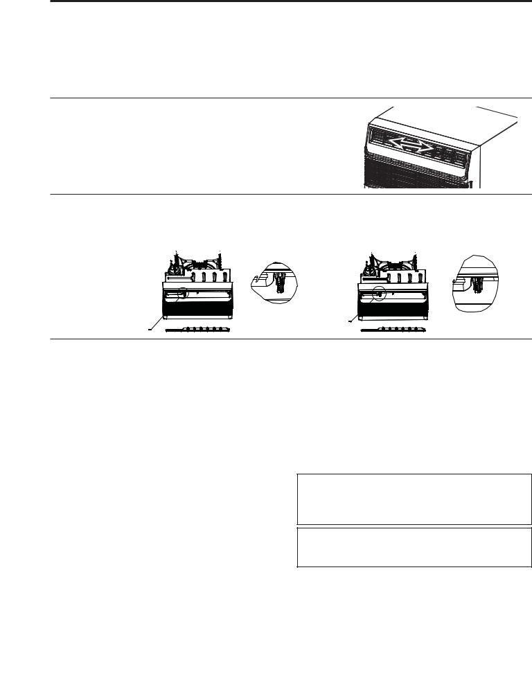
Weather Seal Strips Installation
Ŷ 7R LPSURYH VHDOLQJ RQ QRQ *( :DOO 6OHHYHV RU older wall sleeves that have damaged or missing gaskets, we have provided two foam pads with adhesive that can be installed on the sides of the chassis per the below instructions.
Note: These gaskets may not be necessary with a new RAB26A sleeve install.
1.Remove all packaging and packing material from the unit.
2.Put the chassis on a table or install it
DSSUR[LPDWHO\ ô RI WKH ZD\ LQWR WKH VOHHYH
3.Locate the “bump” or raised area in the metal on each side of the unit right behind the front cover. The foam strip should be located right behind the raised area.
4.Wipe each side with a cloth to make sure the area is clean.
5.Peel the backing off one piece of foam and starting at the top corner of side, adhere it from top to bottom just behind the bump on the flat surface.
6.Repeat on right side ensuring you do not put the foam strip over the removable cover on the right side.
Raised
Area
Removable cover
Locate foam pad here
Left Side |
|
Right Side |
|
|
|
7.When sliding the unit into the sleeve gently compress the pads to help it move behind the flange of the sleeve.
8.Be cautious of the foam pads when removing the unit from the sleeve as well.
Security Brackets Installation
(It is important to install these brackets to prevent the chassis from being pushed into the room from the outside.)
Ŷ The brackets must be installed so the flanges are hooked behind the inside flanges of the wall sleeve.
8VLQJ WKH VFUHZV SURYLGHG DWWDFK WKH EUDFNHWV RQ the sides of the chassis.
To install the security bracket without fully removing the front grille:
1.Grasp the front grille louvers on both sides at the recess and pull forward.
2.Remove the filter by pulling forward and out.
3.Remove the two Phillips head screws located in the upper corners of the grille louver opening. Do not discard screws.
4.Grasp the left and right rear edges of the front grille about 6” from the top and pull outward to release the tabs on the inside of the grille from the slots in each side of the metal chassis cover. When released pull out both bottom corners of the
IURQW JULOOH DERXW ´ WR H[SRVH WKH WZR VFUHZ KROHV on the lower area of the metal chassis cover.
5.Locate the 2 metal brackets stamped 26” that were included with the air conditioner. Hook the short flange of the bracket behind the sleeve inside edge and rotate it so the long side can be pressed flat against the metal chassis cover. Adjust so the bracket can be secured to the metal chassis cover by 2 screws included with the bracket. Only one bracket will be needed and can be installed on either side of the chassis.
6.To reinstall the front grille, push the lower corners to toward the sleeve until the side tabs click into the mating slots. Reinstall the two screws removed earlier and replace the filter and louvers.
For 26” sleeves, hook the short flange of the 26” bracket behind the sleeve inside edge and secure to the unit with the two screws provided. Repeat on the opposite side.
Hook inside sleeve edge and secure to unit
Hook inside sleeve edge and secure 
 to unit
<![endif]>INSTRUCTIONS INSTALLATION
49-5000492 Rev. 4 |
11 |

<![endif]>TROUBLESHOOTING TIPS
Troubleshooting Tips... Before you call for service
Problem |
Solution |
|
Air conditioner does |
Wall plug disconnected. Push plug firmly into wall outlet. |
|
not start |
House fuse blown or circuit breaker tripped. Replace fuse with time delay type |
|
|
or reset circuit breaker. |
|
|
Plug current device tripped. Press the RESET button. |
|
|
Power is OFF. Turn power ON. |
|
Air from the unit does |
Room temperature below 62°F (17°C). Cooling may not occur until room |
|
not feel cold enough |
temperature rises above 62°F (17°C). |
|
|
Temperature sensor behind air filter may be touching cold coil. Keep it from the |
|
|
cold coil. |
|
|
Set to a lower temperature. |
|
|
Compressor stopped when changing modes. Wait for 3 minutes after set to the |
|
|
COOL mode. |
|
Air conditioner cooling, |
Outdoor temperature below 64°F (18°C). To defrost the coil, set FAN ONLY mode. |
|
but room is too warm. |
Air filter may be dirty. Clean the filter. Refer to Care and Cleaning section. To |
|
Ice is forming on |
defrost, set to FAN ONLY mode. |
|
cooling coil behind |
|
|
Thermostat set to cold for night-time cooling. To defrost the coil, set to FAN |
||
decorative front. |
||
ONLY mode. Then, set temperature to a higher setting. |
||
|
||
|
Dirty air filter, or the air is restricted. Clean the air filter. Refer to Care and |
|
|
Cleaning section. |
|
|
Temperature is set too high. Set the temperature to a lower setting. |
|
|
Air directional louvers positioned improperly. Position louvers for better air |
|
|
distribution. |
|
|
Front of unit is blocked by drapes, blinds, furniture, etc, which restricts air |
|
|
distribution. Clear blockage in front of unit. |
|
|
Doors, windows, registers, etc, may be open. Close doors, windows, registers. |
|
|
Unit recently turned on in hot room. Allow additional time to remove “stored |
|
|
heat” from walls, ceiling, floor, and furniture. |
|
Air conditioner turns on |
Dirty air filter, the air is restricted. Clean air filter. |
|
and off rapidly |
Outside temperature extremely hot. Set FAN speed to a higher setting to cool |
|
|
outdoor cooling coil. |
|
Noise when unit is |
Air movement sound. This is normal. If too loud, set to a slower FAN setting. |
|
cooling |
Improper installation. Refer to installation instructions or check with installer. |
|
Water dripping INSIDE |
Improper installation. Tilt air conditioner slightly to the outside to allow water |
|
when unit is cooling |
drainage. Refer to installation instructions, and check with installer. |
|
Water dripping |
Unit removing large quantity of moisture from humid room. This is normal |
|
OUTSIDE when unit is |
during excessively humid days. |
|
cooling |
|
|
Room too cold |
Set temperature to low. Increase set temperature. |
|
Error code “AS” in the |
Room temperature sensor error. Unplug the unit and plug it back in. If error |
|
display |
repeats, call for service. NOTE: In Fan only mode, it will display “LO” or “HI”. |
|
Error code “HS” in the |
Electric heating sensor error. Unplug the unit and plug it back in. If error |
|
display |
repeats, call for service. |
|
Error code “•” in the |
Evaporator temperature sensor error. Unplug the unit and plug it back in. If |
|
display |
error repeats, call for service. |
12 |
49-5000492 Rev. 4 |

Notes
49-5000492 Rev. 4 |
13 |

Notes
14 |
49-5000492 Rev. 4 |
 Loading...