


GE AHM24DWH2, AHM24DWH1, AHM18DWH2, AHM18DWH1, AHM15AWW2 Owner’s Manual
...ROOM |
CONDITIONER |
|
|
||
|
AIR |
|
SAFETY INFORMATION . . . . . . . . .3
USING THE AIR CONDITIONER
Controls . . . . . . . . . . . . . . . . . . . . . . . . . . . . . .4
Remote Control . . . . . . . . . . . . . . . . . . . . . . .5
Cool Mode . . . . . . . . . . . . . . . . . . . . . . . . . . . .5
Energy Saver Mode . . . . . . . . . . . . . . . . . . . .5
Air Direction . . . . . . . . . . . . . . . . . . . . . . . . . .6
CARE AND CLEANING
Grille and Case . . . . . . . . . . . . . . . . . . . . . . . .6
Air Filter. . . . . . . . . . . . . . . . . . . . . . . . . . . . . .6
Outdoor Coils . . . . . . . . . . . . . . . . . . . . . . . . .6
Install Batteries in Remote . . . . . . . . . . . . . .6
INSTALLATION INSTRUCTIONS
Before you begin . . . . . . . . . . . . . . . . . . . . . .7 Electrical Requirements . . . . . . . . . . . . . . . .7 Parts Included . . . . . . . . . . . . . . . . . . . . . . . . .8 Window Requirements . . . . . . . . . . . . . . . . .9 Prepare the Air Conditioner . . . . . . . . . . . . .9 Install the Air Conditioner. . . . . . . . . . . . . . 10 Install Support Brackets . . . . . . . . . . . . . . . 11
TROUBLESHOOTING TIPS. . . . . . 12
Normal Operating Sounds . . . . . . . . . . . . . 13
CONSUMER SUPPORT
Warranty . . . . . . . . . . . . . . . . . . . . . . . . . . . . 15
Consumer Support . . . . . . . . . . . .Back Cover
Write the model and serial numbers here:
Model #_________________
Serial # _________________
You can find the rating label on the left side of the air conditioner.
OWNER’S MANUAL
AHM15
AHM18
AHM24
GE is a trademark of the General Electric Company. Manufactured under trademark license.
49-7765 11-16 GEA

THANK YOU FOR MAKING GE APPLIANCES A PART OF YOUR HOME.
Whether you grew up with GE Appliances, or this is your first, we’re happy to have you in the family.
We take pride in the craftsmanship, innovation and design that goes into every GE Appliances product, and we think you will too. Among other things, registration of your appliance ensures that we can deliver important product information and warranty details when you need them.
Register your GE appliance now online. Helpful websites and phone numbers are available in the Consumer Support section of this Owner’s Manual. You may also mail in the pre-printed registration card included in the packing material.
2 |
|
49-7765 |

IMPORTANT SAFETY INFORMATION
READ ALL INSTRUCTIONS BEFORE USING THE APPLIANCE
 WARNING For your safety, the information in this manual must be followed to minimize the risk of fire, electric shock or personal injury.
Ŷ 8VH WKLV DSSOLDQFH RQO\ IRU LWV LQWHQGHG SXUSRVH DV described in this Owner’s Manual.
Ŷ This air conditioner must be properly installed in accordance with the Installation Instructions before it is used.
Ŷ Never unplug your air conditioner by pulling on the power cord. Always grip plug firmly and pull straight out from the receptacle.
Ŷ Replace immediately all electric service cords that have become frayed or otherwise damaged. A damaged power supply cord must be replaced with a new power supply cord obtained from the manufacturer and not repaired. Do not use a cord that shows cracks or abrasion damage along its length or at either the plug or connector end.
Ŷ Turn the unit OFF and unplug your air conditioner before cleaning.
Ŷ For your safety, do not store or use combustible materials, gasoline or other flammable vapors or liquids in the vicinity of this or any other appliance.
Ŷ All air conditioners contain refrigerants, which under federal law must be removed prior to product disposal. If you are getting rid of an old product with refrigerants, check with the company handling disposal about what to do.
Ŷ If the receptacle does not match the plug, the receptacle must be changed out by a qualified electrician.
Ŷ These R410A air conditioning systems require contractors and technicians to use tools, equipment and safety standards approved for use with this refrigerant. DO NOT use equipment certified for R22 refrigerant only.
Ŷ To avoid risk of injury or property damage, the air conditioner should ONLY be serviced by a qualified servicer.

 WARNING USE OF EXTENSION CORDS
RISK OF FIRE. Could cause serious injury or death. |
Ŷ '2 127 XVH VXUJH SURWHFWRUV RU PXOWL RXWOHW DGDSWRUV |
Ŷ '2 127 XVH DQ H[WHQVLRQ FRUG ZLWK WKLV :LQGRZ $LU |
with this Window Air Conditioner. |
|
|
Conditioner. |
|
HOW TO CONNECT ELECTRICITY
Do not, under any circumstances, cut or remove the third (ground) prong from the power cord. For personal safety, this appliance must be properly grounded.
DO NOT use an adapter plug with this appliance.
The power cord of this appliance is equipped with a 3-prong (grounding) plug which mates with a standard 3-prong (grounding) wall outlet to minimize the possibility of electric shock hazard from this appliance.
Power cord includes a current interrupter device. A test and reset button is provided on the plug case. The device should be tested on a periodic basis by first pressing the TEST button and then the RESET button while plugged into the outlet. If the TEST button does not trip or if the RESET button will not stay engaged, discontinue use of the air conditioner and contact a qualified service technician.
Have the wall outlet and circuit checked by a qualified electrician to make sure the outlet is properly grounded.
Where a 2-prong wall outlet is encountered, it is your personal responsibility and obligation to have it replaced with a properly grounded 3-prong wall outlet.
The air conditioner should always be plugged into its own individual electrical outlet which has a voltage rating that matches the rating plate.
This provides the best performance and also prevents overloading house wiring circuits which could cause a fire hazard from overheated wires.
See the Installation Instructions, Electrical Requirements section for specific electrical connection requirements.
READ AND SAVE THESE INSTRUCTIONS
INFORMATION SAFETY
49-7765 |
3 |

USING THE AIR CONDITIONER
Controls
Features and appearance will vary.
Lights below the touch pads on the air conditioner control panel indicate the selected settings.
|
2 |
Unit power |
|
|
on/off |
|
|
|
|
Mode select |
|
|
|
Fan speed |
|
6 |
|
Delay 1–24hr |
|
|
|
|
|
4 |
3 |
Temperature |
|
5 |
set/Delay Timer |
|
|
|
Increase and |
Temp / Delay Hrs |
|
|
|
Decrease |
- |
|
|
|
|
|
1 |
|
|
|
7 |
|
|
Air Conditioner Controls |
Remote Control |
Controls
1. Power Pad
Turns air conditioner on and off. When turned on, the display will show the room temperature.
2. Display
Shows the room temperature or time remaining on the Delay timer. Shows the Set temperature while setting the temperature in Cool or Energy Saver modes.
3. Temp and Delay Increase + /Decrease – Pads
8VH WR VHW WHPSHUDWXUH RU GHOD\ WLPH 7HPSHUDWXUH can be set in Cool and Energy Saving mode.
4. Mode Pad
8VH WR VHW WKH DLU FRQGLWLRQHU WR Fan Only, Cool, or
Energy Saver mode.
5. Fan Speed Pad
In Cool, Energy Saving mode:
8VH WR VHW WKH IDQ VSHHG WR Auto, High, Med or Low on the unit.
In Fan Only mode:
8VH WR VHW WKH IDQ VSHHG WR High, Med, or Low on the unit.
6. Delay Pad
Shows the room temperature or time remaining on the Delay timer. Shows the Set temperature while setting the temperature in Cool or Energy Saver modes.
Delay ON—When the air conditioner is off, it can be set to automatically come on in 1 to 24 hours at its previous mode and fan settings.
Delay OFF—When the air conditioner is on, it can be set to automatically turn off in 1 to 24 hours.
How to set:
Press the Delay 1–24hr pad on the unit or the remote control. Each touch of the Increase + / Decrease – pads on the unit or the remote control will set the timer in 1-hour intervals.
To review the remaining time on the Delay 1–24hr timer, press the Delay 1–24hr pad on the unit or the
UHPRWH FRQWURO 8VH WKH Increase + / Decrease – pads on the unit or on the remote control to set a new time if desired.
To cancel the timer, press Decrease – pad on the unit or the remote control until the set time is zero. After 3 seconds the light on the Delay 1-24 hour pad goes off.
7. Filter Reset Pad
This feature automatically notifies you that the air filter must be cleaned. The indicator light will come on after 240 hours of operation. Clean the air filter (refer to page 6), place it back in the front panel, and press the Filter Reset pad. The light will go off.
4 |
49-7765 |

Using the Air Conditioner
Do Not Operate in Freezing Outdoor Conditions
This cool-only air conditioner was not designed for freezing outdoor conditions. It must not be used when the outdoor temperature is below freezing (32°F).
Remote Control
Ŷ To ensure proper operation, aim the remote control at the |
Ŷ Make sure nothing is between the air conditioner and the |
signal receiver on the air conditioner. |
remote control that could block the signal. |
Ŷ The remote control signal has a range of up to 20 feet. |
Ŷ Make sure batteries are fresh and installed correctly as |
|
indicated on the remote control. |
|
|
Cool Mode
8VH WKH &RRO PRGH DW Low, Med, High or Speed for
FRROLQJ 8VH WKH Temperature Increase + / Decrease – pads to set the desired temperature between 61°F and 86°F in 1°F increments.
An electronic thermostat is used to maintain the room temperature. The compressor will cycle on and off
to keep the room at the set level of comfort. Set the thermostat at a lower number and the indoor air will become cooler. Set the thermostat at a higher number and the indoor air will become warmer.
NOTE: If the air conditioner is off and is then turned on while set to a Cool setting or if turned from a fan setting
to a Cool VHWWLQJ LW PD\ WDNH DSSUR[LPDWHO\ PLQXWHV IRU the compressor to start and cooling to begin.
Cooling Descriptions
For Normal Cooling—Select the Cool mode and
High or Med fan with a middle set temperature.
For Maximum Cooling—Select the Cool mode and High fan with a lower set temperature.
For Quieter and Nighttime Cooling—Select the
Cool mode and Low fan with a middle set temperature.
Energy Saver Mode
Controls the fan.
ON—The fan will cycle on and off with the compressor. This may result in wider variations of room temperature and humidity. NOTE: the fan may continue to run
for a short time or may pulse intermittently after the compressor cycles off to sample the room air.
OFF—The fan runs all the time, while the compressor cycles on and off.
Fan Only Mode
8VH WKH )DQ 2QO\ 0RGH DW /RZ 0HG RU +LJK IDQ VSHHG to provide air circulation and filtering without cooling. Since fan-only settings do not provide cooling, a Set temperature cannot be entered. The room temperature will appear in the display.
Auto Fan Mode
Set to Auto for the fan speed to automatically set to the |
If the unit is in Cool or Energy Saver mode and the room |
speed needed to provide optimum comfort settings with |
needs more cooling, the fan speed will automatically |
the set temperature. |
increase. If the room needs less cooling, the fan speed |
|
will automatically decrease. |
CONDITIONER AIR THE USING
49-7765 |
5 |
CARE AND CLEANING
Using the Air Conditioner
Air Direction
8VH WKH OHYHU WR DGMXVW WKH DLU GLUHFWLRQ OHIW ULJKW XS DQG down.
Care and Cleaning
Grille and Case
Turn the air conditioner off and remove the plug from the |
To clean, use water and a mild detergent. Do not use |
wall outlet before cleaning. |
bleach or abrasives. |
|
|
Air Filter |
|
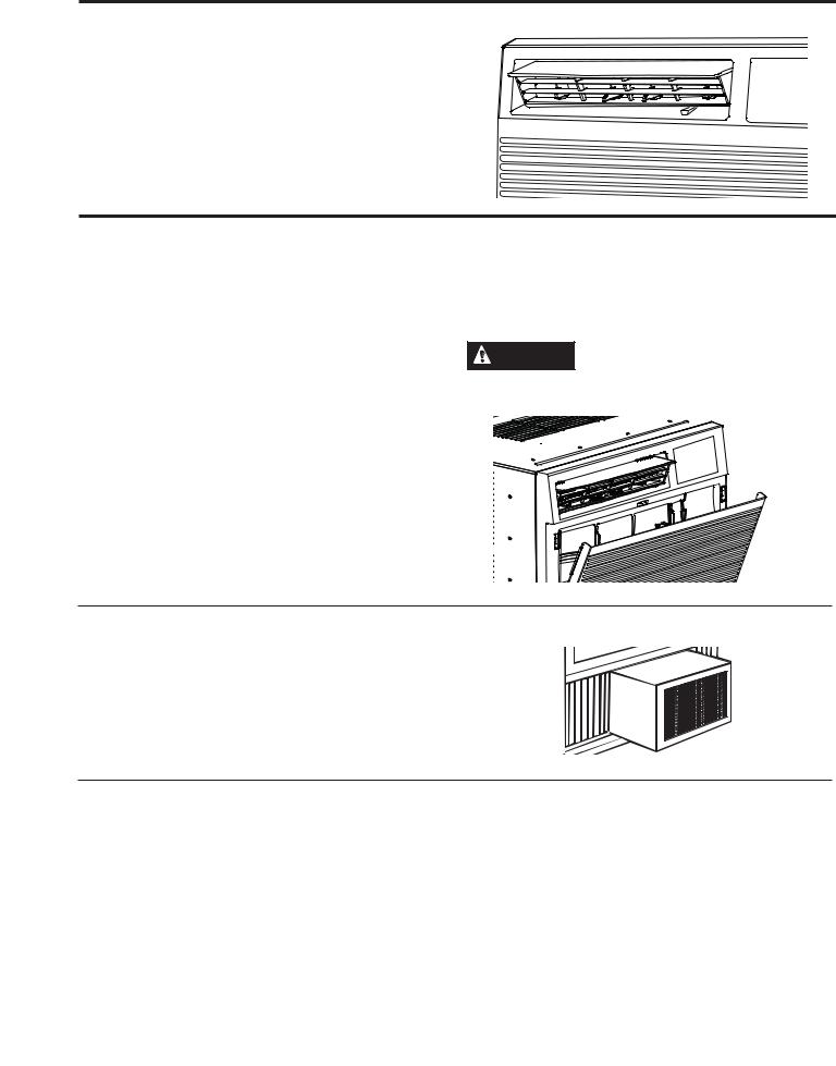
The air filter behind the front grille should be checked and cleaned at least every 30 days or more often if necessary.
To remove:
Open the inlet grille by pulling downward on the tabs at the top upper corners of the inlet grille until the grille is in a 45º position. Remove the filter.
Clean the filter with warm, soapy water. Rinse and let the filter dry before replacing it. Do not clean the filter in a dishwasher.
CAUTION |
DO NOT operate the air conditioner |
|
without a filter because dirt and lint will clog it and reduce performance.
Outdoor Coils
The coils on the outdoor side of the air conditioner should be checked regularly. If they are clogged with dirt or soot, they may be professionally cleaned.
How to Insert the Battery in the Remote Control
1.Remove the screw on the back of the battery cover.
2.Pinch the slide lock and pull the battery tray out at the same time.
3.Insert new battery, making sure that the (+) and (–) of battery are installed correctly.
4.Reinsert the battery tray and put the reinstall the screw.
NOTES:
Ŷ 8VH RQH &5 9 /LWKLXP EDWWHU\
Ŷ Remove the battery from the remote control if the system is not going to be used for a long time.
6 |
49-7765 |
Installation Instructions
Questions? Call 800.GE.CARES (800.432.2737) or Visit our Website at: GEAppliances.com
BEFORE YOU BEGIN
Read these instructions completely and carefully.
• IMPORTANT – Save these
instructions for local inspector’s use.
• IMPORTANT – Observe all
governing codes and ordinances.
•Note to Installer – Be sure to leave these instructions with the Consumer.
•Note to Consumer – Keep these instructions for future reference.
•Skill level – Installation of this appliance requires basic mechanical skills.
•Completion time ± $SSUR[LPDWHO\ KRXU
•We recommend that two people install
this product.
•Proper installation is the responsibility of the installer.
•Product failure due to improper installation is not covered under the Warranty.
<RX 0867 XVH DOO VXSSOLHG SDUWV DQG XVH SURSHU installation procedures as described in these instructions when installing this air conditioner.
ELECTRICAL REQUIREMENTS
Models AHM18 and AHM24
The 3-prong grounding plug minimizes the possibility of electric shock hazard. If the wall outlet you plan to use is only a 2-prong outlet, it is your responsibility to have it replaced with a properly grounded 3-prong wall outlet.
These models require 230/208-volt AC, protected with a time-delay fuse or circuit breaker. These models should be installed on their own single branch circuit for best performance and to prevent overloading house or apartment wiring circuits, which could cause a possible fire hazard from overheating wires.
Model AHM15
These models require a 115/120-volt AC, 60-Hz grounded outlet protected with a
15-amp time-delay fuse or circuit breaker.
The 3-prong grounding plug minimizes the possibility of electric shock hazard. If the wall outlet you plan to use is only a 2-prong outlet, it is your responsibility to have it replaced with a properly grounded 3-prong wall outlet.
ELECTRICAL REQUIREMENTS (CONT)

 CAUTION
Do not, under any circumstances, cut or remove the third (ground) prong from the power cord.
Do not change the plug on the power cord of this air conditioner.
Aluminum house wiring may present special problems—consult a qualified electrician.
Power cord includes a current interrupter device. A test and reset button is provided on the plug case. The device should be tested on a periodic basis by first pressing the TEST button and then the RESET button while plugged into the outlet. If the TEST button does not trip or if the RESET button will not stay engaged, discontinue use of the air
conditioner and contact a qualified service technician.
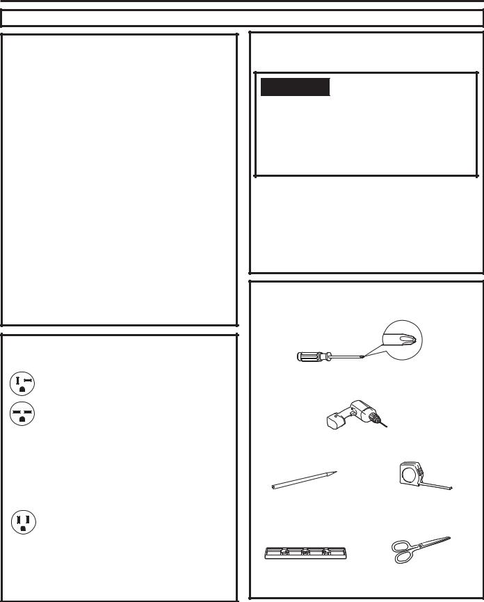
TOOLS YOU WILL NEED
Phillips head screwdriver
Drill and 1/8” drill bit
Pencil |
|
Ruler or tape measure |
|
|
|
/HYHO |
|
Scissors or knife |
|
|
|
|
|
|
INSTRUCTIONS INSTALLATION
49-7765 |
7 |

INSTALLATION INSTRUCTIONS
Installation Instructions
PARTS INCLUDED |
|
|
|
|
||
(Appearance may vary) |
|
|
|
|
||
Top Mounting Rail |
Foam Seal |
|
|
|||
|
|
|
|
|||
(may be installed |
|
|
|
Side Curtain |
||
|
already) |
|
|
Side Curtain |
|
Frame |
|
|
|
|
/HIW |
Right |
|
Air |
|
|
|
(2) |
||
|
|
|
|
|
|
|
Conditioner |
|
|
|
|
|
|
|
|
|
|
|
|
Temp / Delay Hrs |
|
|
|
|
|
|
- |
Installation |
:LQGRZ /RFN |
|
Side Curtain |
|
|
|
Bracket (2) |
|
Bracket |
|
Foam (2) |
|
Remote Control |
|
|
|
|
|
|
|
|
A |
B |
C |
D |
|
|
3/8” Self-tapping |
3/8” Bracket |
1” Wood |
2-1/2” Flat Head Bolt and |
|
||
|
Screws (12) |
Screws (6) |
Screws (8) |
/RFN 1XW |
|
|
8 |
|
|
|
|
|
49-7765 |

Installation Instructions
1.WINDOW REQUIREMENTS
•These instructions are for a standard double-hung window. You will need to modify them for other types of windows.
•The air conditioner can be installed without the side curtain panels if needed to fit in a narrow window. See the window opening dimensions.
•All supporting parts must be secured to firm wood, masonry or metal.
•The electrical outlet must be within reach of the power cord.
•Follow the dimensions in the table and illustration for your model.
Models |
A |
B |
AHM15 |
19 1/8” min |
30”-39” |
AHM18 |
||
AHM24 |
|
|
A
B
(With side curtain panels)
3.PREPARE THE AIR CONDITIONER
A.Remove three screws on each side of the case. Save the screws for use later.
B.Insert a flat head screw driver between the front grille and the metal case along the sides. Gently pry the grille from the case.
NOTE: Cover the flat head screw driver with tape to prevent scratching the case.
C. 8VLQJ WKH KDQGOH RQ WKH ERWWRP IURQW RI WKH DLU conditioner, pull the air conditioner out of the case. The air conditioner is very heavy so make sure that it will be resting on a sturdy surface.
Save these screws for later use.
2. STORM WINDOW REQUIREMENTS
A storm window frame will not allow the air conditioner to tilt toward the outside, and will keep it from draining properly. To adjust for this, attach a piece of wood to the sill.
WOOD PIECES WIDTH: 2Ǝ
LENGTH: /RQJ HQRXJK WR ILW LQVLGH WKH ZLQGRZ frame.
THICKNESS: To determine the thickness, place
D SLHFH RI ZRRG RQ WKH VLOO WR PDNH LW Ǝ KLJKHU than the top of the storm window frame or the vinyl frame.
Attach securely with nails or screws provided by the installer.
Ǝ KLJKHU |
than storm |
window |
frame |
Storm window |
frame |
Ǝ KLJKHU than vinyl frame
(on some windows)
Wood
Sill
Vinyl frame
INSTRUCTIONS INSTALLATION
49-7765 |
9 |

INSTALLATION INSTRUCTIONS
Installation Instructions
4. PREPARE THE CASE
NOTE: Attach curtains to the air conditioner before placing the air conditioner in the window.
A. Install top mounting rail (if not already installed) with four type A screws.
3/8” Self Tapping
Screws
B.Slide left-hand curtain assembly into left end of top and bottom mounting rail. Repeat for right hand curtain assembly.
C.Fasten curtain retainer strips to the sides of the outer case with four type A screws on each side.
KROHV 8VH W\SH % VFUHZV WR VHFXUH WKH VLGH panels in place.
Top Channel
Side Curtains |
3/8” Self Tapping |
|
Screws |
5.PREPARE WINDOW FOR INSTALLATION
A.Measure the width of the window opening.
B.Mark the center line on the inside windowsill.
A
B
A.Width of window opening
B.Center line
10 |
49-7765 |
 Loading...