


Gateway®7400 Server
System Manual
October 2001
8508366

Notices
Copyright © 2001 Gateway, Inc.
All Rights Reserved
4545 Town Centre Court
San Diego, CA 92121 USA
All Rights Reserved
This publication is protected by copyright and all rights are reserved. No part of it may be reproduced or
transmitted by any means or in any form, without prior consent in writing from Gateway.
The information in this manual has been carefully checked and is believed to be accurate. However, changes
are made periodically. These changes are incorporated in newer publication editions. Gateway may improve
and/or change products described in this publication at any time. Due to continuing system improvements,
Gatewayis not responsible for inaccurate information which may appear in this manual. For the latest product
updates, consult the Gateway Web site at www.gateway.com. In no event will Gateway be liable for direct,
indirect, special, exemplary, incidental, or consequential damages resulting from any defect or omission in
this manual, even if advised of the possibility of such damages.
In the interest of continued product development, Gateway reserves the right to make improvements in this
manual and the products it describes at any time, without notices or obligation.
Trademark Acknowledgments
1-800-GATEWAY, ActiveCPR, ALR, AnyKey, black-and-white spot design, CrystalScan, Destination, DestiVu,
EZ Pad, EZ Point,Field Mouse, Gateway 2000, GatewayCountry, gateway.net, Gateway stylized logo, Perfect
Scholar, Solo, TelePath, Vivitron, stylized “G” design, and “You’ve got a friend in the business” slogan are
registered trademarks and black-and-white spotted box logo, GATEWAY, Gateway Astro, Gateway@Work,
Gateway Connected touch pad, Gateway Connected music player, Gateway Cyber:)Ware, Gateway
Education:)Ware, Gateway Flex Case, Gateway Gaming:)Ware, Gateway GoBack, Gateway Gold, Gateway
Learning:)Ware, Gateway Magazine, Gateway Micro Server, Gateway Money:)Ware, Gateway Music:)Ware,
Gateway Networking Solutions, Gateway Online Network (O.N.) solution, Gateway Photo:)Ware, Gateway
Professional PCs, Gateway Profile, Gateway Solo, green stylized GATEWAY, green stylized Gateway logo,
Gateway Teacher:)Ware, Gateway Video:)Ware, HelpSpot, InforManager, Just click it!, Learn@Gateway, Kids
BackPack,SERVE-TO-ORDER, Server Watchdog, SpotShop, Spotshop.com, and Your:)Ware are trademarks
of Gateway, Inc. Intel, Intel Inside logo, and Pentium are registered trademarks and MMX is a trademark of
Intel Corporation. Microsoft, MS, MS-DOS, and Windows are trademarks or registered trademarks of Microsoft
Corporation. All other product names mentioned herein are used for identification purposes only, and may be
the trademarks or registered trademarks of their respective companies.

Contents
Preface.............................................................vii
Conventions used in this manual .......................................vii
Getting additional information . . .......................................viii
1 System Features ................................................1
Standardfeatures ...................................................1
Front panel ........................................................2
Back panel .........................................................4
Interiorofsystem....................................................6
System board ......................................................8
SCSI backplane board ..............................................10
Backside......................................................10
Frontside .....................................................11
Front panel board . . ................................................12
2SystemSetup..................................................15
Settinguptheserver................................................15
Installingtheoutriggersandcastors ....................................16
Startingtheserver..................................................17
Understanding the Power-On Self-Test ..............................18
Settinguptheoperatingsystem....................................18
Turningofftheserver ...............................................19
Resettingtheserver ................................................20
3 Case Access ...................................................21
Preventingstaticelectricitydischarge...................................22
Openingthecase ..................................................23
Opening the bezel door . . . .......................................24
Removingthebezel .............................................25
Removing the side cover panel ....................................26
Closingthecase ...................................................27
Replacingthesidepanel .........................................27
Replacingthebezel .............................................28
4 Replacing and Adding System Components ...................29
Drives............................................................30
Preparing to replace or add a drive . . . ..............................30
Drivecablinginformation .........................................31
iii

Replacingthediskettedrive........................................31
Replacing an optional drive . . ......................................33
Installinga3.5-inchdriveina5.25-inchdrivebay ......................35
Replacingahot-plugdrive .........................................38
Addingahot-plugdrive ...........................................42
ReplacingtheCDdrive ...........................................47
Addingadditional5.25-inchdevices .................................49
Replacingoraddingmemory ..........................................51
Replacingoraddingaprocessor .......................................55
Replacingthebattery ................................................60
Expansion cards ....................................................63
Replacing an expansion card ......................................63
Addinganexpansioncard .........................................65
Power supplies .....................................................68
Replacing a redundant power supply module ..........................68
Replacing the power supply . . ......................................70
Replacing the back panel and drive cage fans ............................73
Replacing the control panel board ......................................75
ReplacingtheSCSIbackplane.........................................77
Replacing the system board ...........................................80
5 Using the BIOS Setup Utility ....................................85
About the BIOS Setup utility ...........................................85
Updating the BIOS . . . ...............................................87
Settingtheconfigurationswitches ......................................88
TheClearPasswordswitch ........................................88
TheClearCMOSswitch ..........................................89
6 Managing Your System .........................................91
Protecting against power source problems . . .............................91
Surge suppressors ...............................................91
Line conditioners . ...............................................92
Uninterruptible power supplies ......................................92
Maintaining and managing your hard drive . . .............................93
Hard drive maintenance utility ......................................93
Harddrivemanagementpractices...................................94
Protectingyourserverfromviruses..................................96
Systemadministrationandcontrol ......................................98
ManageX Event Manager . . . ......................................98
Gateway® servermanagementsoftware .............................98
Systemsecurity .................................................98
Systemrecovery ...................................................101
Creatingastartupdiskette ........................................101
iv

Using your Server Companion CD .................................101
7 Cleaning the Server ...........................................103
Cleaning the mouse ...............................................103
Cleaning the keyboard .............................................104
Cleaning the monitor screen . . . ......................................104
Cleaning the server and monitor cases . . . .............................104
8 Troubleshooting ...............................................105
Introduction ......................................................105
Troubleshooting checklist ...........................................106
Verifyingyourconfiguration ......................................106
Troubleshootingguidelines .......................................106
CDdriveproblems.................................................107
Diskettedriveproblems.............................................109
Harddriveproblems ...............................................110
Memoryandprocessorproblems .....................................111
Modem problems . . . ...............................................112
Peripheral/adapter problems . . . ......................................113
Printerproblems ..................................................114
Systemproblems..................................................116
Videoproblems ...................................................118
Error messages ...................................................120
A Safety and Regulatory Information ............................125
B System Specifications ........................................133
Environmentalspecifications .........................................134
System I/O addresses ..............................................135
Memorymap .....................................................138
Interrupts ........................................................138
DMAusage ......................................................139
Index..............................................................141
v

vi
Preface
Conventions used in this manual
Throughout this manual, you will see the following conventions:
Convention Description
ENTER Keyboard key names are printed in small capitals.
C
TRL+ALT+DEL Aplussignmeanstopressthekeysatthesametime.
Setup Commands to be entered, options to select, and messages that
appear on your monitor are printed in bold.
User’s Guide Names of publications are printed in italic.
Viewpoint All referencesto front, rear, left, or right on the computer are based
on the computer being in a normal, upright position, as viewed from
the front.
Important A note labeled important informs you of special
circumstances.
Caution A caution warns you of possible damage to equipment or
loss of data.
Warning A warning indicates the possibility of personal injury.
Conventions used in this manual vii

Getting additional information
Log on to the Technical Support area at www.gatewayatwork.com to find
information about your system or other Gateway products. Some types of
information you can access are:
■ Hardware driver and program updates
■ Technical tips
■ Service agreement information
■ Technical documents and component information
■ Frequently asked questions (FAQs)
■ Documentation for peripherals or optional components
■ Online Technical Support
viii Preface

System Features
Standard features
■ As many as two Pentium
MHz Front Side Bus (FSB)
■ Four Dual Inline Memory Module (DIMM) sockets, that support up to
2 GB of PC133 Synchronous Dynamic Random Access Memory (SDRAM)
■ RCC Champion LE 3.0 North Bridge (CNB30LE) chipset
■ Integrated Intel 82559 LAN
■ Integrated dual-channel Ultra3/U160 SCSI
■ Integrated ATI Rage-XL VGA controller with 4 MB of PC100 SDRAM
■ Seven PCI slots (two 64-bit/33 MHz slots and five 32-bit/33 MHz slots)
■ One 3.5 inch 1.44 MB diskette drive, one CD drive, and one hard drive
■ Integrated Voltage Regulator Modules (VRMs) for both processors
■ Keyboard port (PS/2
two Universal Serial Bus (USB) ports, one RJ-45 LAN connector, and one
VGA port
®
®
), mouse port (PS/2), two serial ports, parallel port,
1
III (FC-PGA Socket 370) processors with 133
Standard features 1
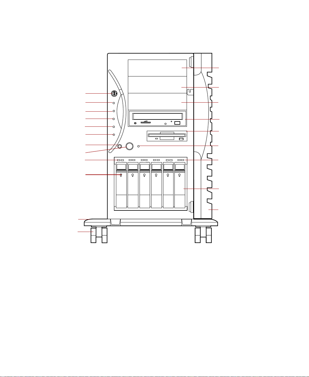
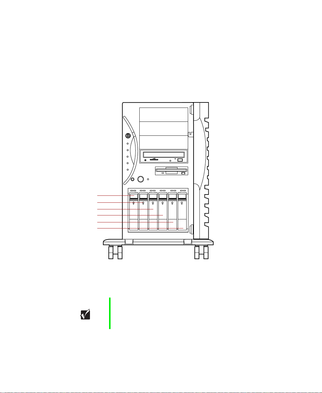
Front panel
Chassis lock
Power LED
Disk activity LED
System fault LED
PS 1 status LED
PS 2 status LED
System reset
button
Power button
Reserved
Hot-plug drive lock
5.25” drive bay
5.25” drive bay
5.25” drive bay
CD drive
Diskette drive
Powersupplyalarm
speaker reset
/system fault LED
reset switch
Hot-plug drive
activity LED
Hot-plug
drive bay
Outriggers
Castors
Chassis lock prevents unauthorized access to both the front panel controls
and to the interior of the system by locking the front bezel to the chassis.
Power LED glows green whenever the system is turned on. The LED also
flashes when the system is in sleep mode.
Disk activity LED glows green whenever a drive is actively reading or writing
data.
System fault LED (yellow) indicates ECC (Error Checking and Correcting)
memory system fault (steady indicates an uncorrectable ECC fault and
blinking indicates a correctable ECC fault).
2 System Features
Frontpanel door
(shown open)

PS 1 status LED glows green when the first power supply module in the
redundant power supply is installed and working correctly. It flashes green if
the power supply module fails or one of its power levels goes out of bounds.
If the power supply module is not installed, this LED is off.
PS 2 status LED glows green when the second power supply module in the
redundant power supply is installed and working correctly. It flashes green if
the power supply module fails or one of its power levels goes out of bounds.
If the power supply module is not installed, this LED is off.
System reset button is a recessed button that lets you reset the server if it
becomes nonresponsive.
Power button turns the server on and off. In an ACPI-enabled operating
system like Windows 2000, you can set the power button to enter sleep mode
rather than turning the system off.
Hot-plug drive lock secures the drive in place to prevent unauthorized or
accidental removal.
Outriggers provide support for the castors.
Castors let you roll the server around for ease of service.
5.25-inch drive bays (3) have room for additional 5.25-inch devices such as
tape drives or an additional CD drive.
CD drive plays data or audio CDs.
Diskette drive writes to and reads from 3.5-inch, 1.44 MB diskettes.
Power supply alarm speaker reset/System fault LED reset switch disables
the power supply alarm speaker, if it’s sounding, or resets the system fault
LED, if it’s flashing. Even though the switch resets the speaker, the power
supply alarm is not cleared and the appropriate LED continues to flash until
the failed power supply module is replaced.
Hot-plug drive activity LED indicates when the hot-plug drive immediately
below it is reading or writing data.
Hot-plug drive bay has room for up to six hot-plug drives connected to a
hot-plug backplane. Drives have to be set up in appropriate RAID
configuration to be hot-pluggable. Removing a drive when it is not properly
configured will result in lost data and may corrupt the operating system.
Front panel door covers the front panel controls to prevent unauthorized or
accidental access.
Front panel 3
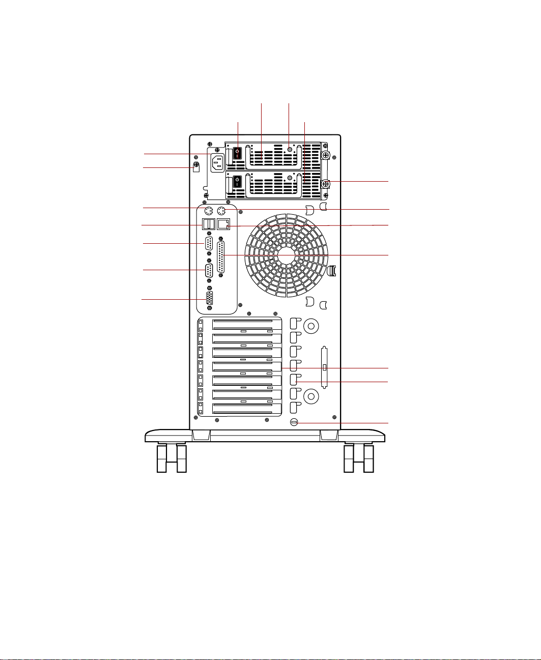
Back panel
Power connector
Power supply
cable clamp
Keyboard port
USB ports
Serial port A
Serial port B
Video port
Power supply module
Module power switch
Power supply module LED
Power supply module
Redundant
power supply
Mouse port
RJ-45 LAN port
Parallel port
Expansion
card slots
Expansion card
retention clips
Power supply modules (2) provide redundant power and hot-plug capability
to power the server with minimal downtime.
Module power switches (2) provide independent power control for each
redundant power supply module.
Power connector connects to the server power cord. The other end of the
power cord plugs into an AC outlet or power strip.
4 System Features
Kensington
lock slot

Power supply cable clamp secures the power supply cords so that they are
not accidentally pulled from the power supply.
Keyboard port connects to a PS/2-compatible keyboard.
USB ports connect to external Plug-and-Play devices, such as printers, that
are automatically configured when they are plugged into the server through
one of these ports. USB keyboards and mice are not supported.
Serial ports (2) connect to serial devices.
Video port connects to the monitor interface cable. The video controller is
integrated in the system board.
Power supply module LED glows steady green when the power supply
module is operating normally.
Redundant power supply provides two hot-pluggable power supply modules
that can independently support the power requirements of the server.
Mouse port connects to a PS/2-compatible mouse.
RJ-45 LAN port connects to a network. The adjacent indicator LEDs show
LAN activity (yellow) and 100 Mbit speed (green).
Parallel port connects to a printer or other parallel device.
Expansion card slots (7) have room for as many as seven PCI expansion
cards.
Expansion card retention clips (7) allow screwless retention of the
expansion cards for ease of maintenance and installation.
Kensington lock slot provides a place to install a security cable and lock.
Back panel 5
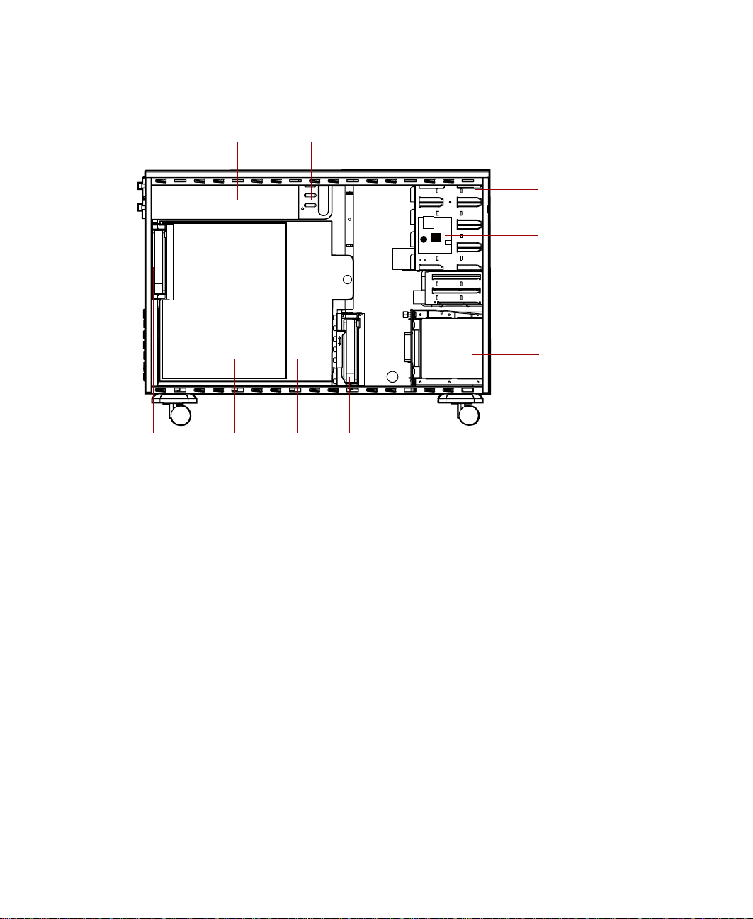
Interior of system
Power supply Power supply fans
5.25-inch
drive bays
N+1 power supply
alarm board
3.25-inch
drive bays
Hot-plug bays
(Hot-plug cage)
Back
panel fan
System
board
System
board tray
Drive
cage fan
SCSI
backplane
Power supply provides power to the system components. The redundant
power supply provides hot-plug capability and fault tolerance.
Power supply fans provide cooling for the redundant power supply modules.
5.25-inch drive bays provide space for as many as four 5.25-inch drives. A
CD drive comes standard with the system and occupies one of the 5.25-inch
drive bays.
N+1 power supply alarm board provides an audible alarm if a power supply
module fails.
3.25-inch drive bays support as many as two 3.25-inch drives. A diskette drive
comes standard with the system and occupies one 3.25-inch drive bay. A hard
drive is typically installed in the second drive bay.
Hot-plug bays support as many as six 1-inch high 3.25-inch SCA SCSI hard
drives. Drive bays without hard drives contain empty drive carriers to control
airflow and EMC emissions.
6 System Features

SCSI backplane provides the control for the hot-plug drives.
Drive cage fan provides cooling for the hot-plug drives and other internal
components.
System board tray supports the system board and makes it easier to remove
and install.
System board (See “System board” on page 8.)
Back panel fan provides cooling for system board components and additional
cooling for the power supply.
Interior of system 7
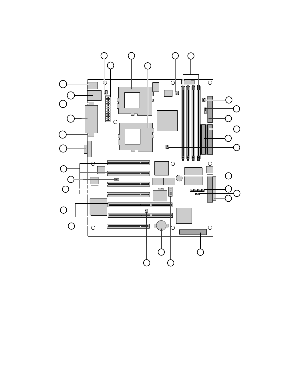
System board
AE
AC
AA
A
B
AD
AB
Z
Y
X
W
V
C
D
E
F
G
H
I
J
K
L
M
N
O
P
U
A Rear chassis fan connector
B Main ATX power connector
C CPU 1 socket
D CPU 2 socket
E CPU 1 Fan connector
8 System Features
S
T
R
Q

DIMM sockets (3 to 0, right to left)
F
G Front chassis fan connector
2
H I
C SMB header
I Floppy drive connector
J Primary IDE connector
K Secondary IDE connector
L CPU 2 fan connector
M Speaker
N Front panel connector
O Auxiliary HDD activity LED connector
P U160 LVD SCSI Channel A connector
Q U160 LVD SCSI Channel B connector
R Configuration switch
S Battery
T (not used)
U PCI 32-bit/33 MHz slot
V PCI 64-bit/33 MHz slots (2)
W (not used)
X (not used)
Y PCI 32-bit/33 MHz slots (4)
Z Video port
AA Serial port B
AB Parallel port
AC Serial port A
AD RJ-45 Ethernet and USB ports 1 and 2
AE PS/2 Keyboard and mouse ports
System board 9
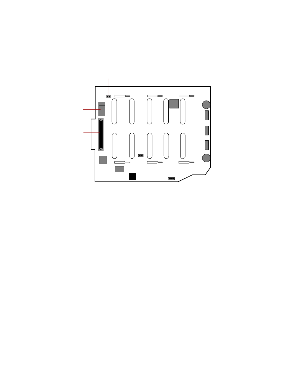
SCSI backplane board
Back side
JP5: Delay start jumper
Power connector
SCSI connector
JP6: Termination jumper
JP5: Delay start jumper controls the spin-up sequence of the drives attached
to the backplane. If you leave the delay start jumper on (enabled - default),
the drives spin up one at a time in order of their SCSI ID. If you remove the
delay start jumper, all drives spin up simultaneously, which may cause an
excessive drain on the system power supply.
JP6: Termination jumper - The backplane is designed to occupy one end of
the bus and is terminated (jumper off - default).
SCSI connector provides the point of connection for the SCSI cable from the
hot-plug controller.
Power connector provides the point of connection for the power cable from
the power supply.
10 System Features
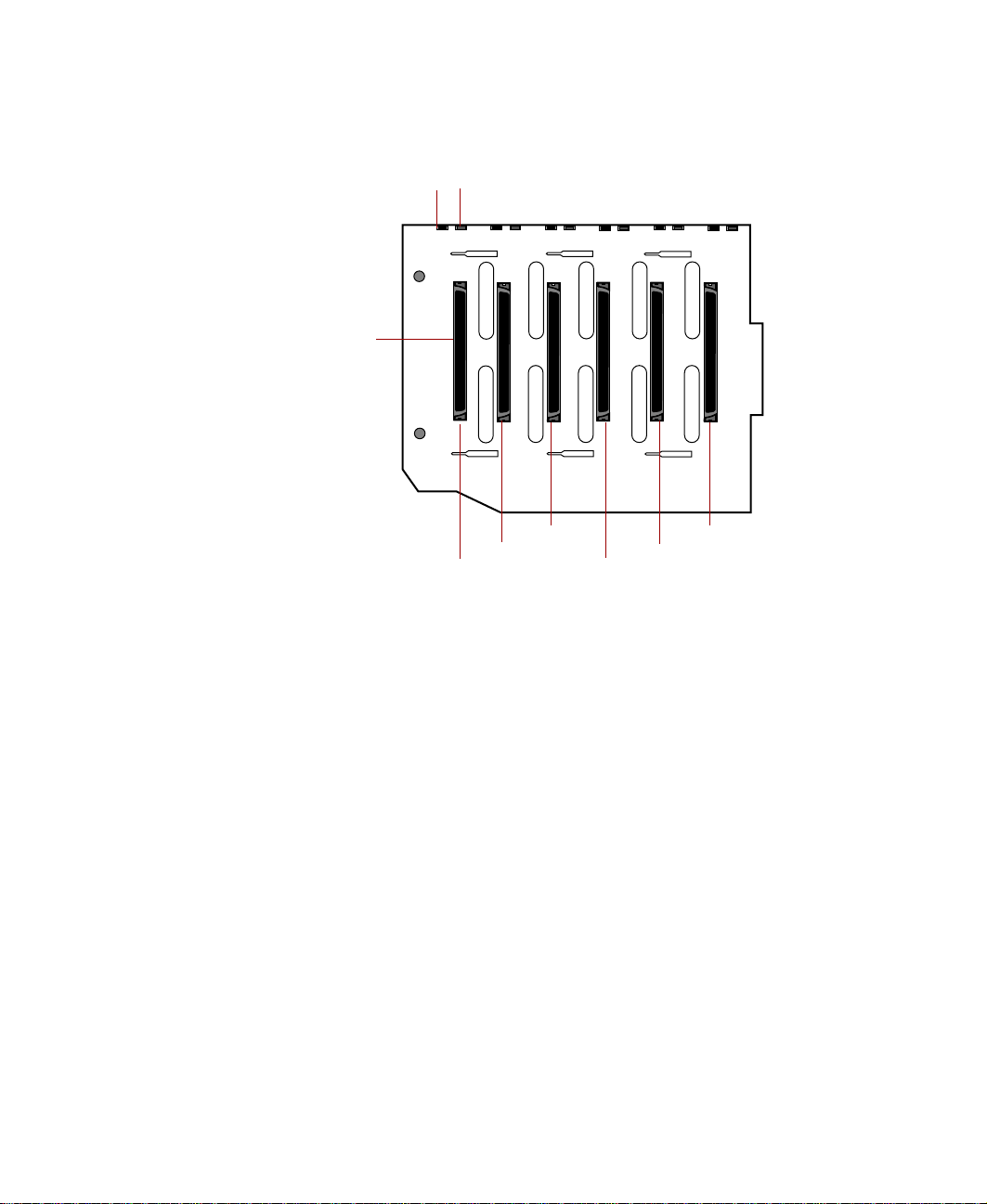
Front side
Reserved LED (6)
SCA SCSI drive connectors (6)
Reserved LED (6) reserved for future use.
Drive activity LED (6) flashes green when the drive is actively reading or
writing data.
SCA SCSI drive connectors (6) provide points of connection for six SCA SCSI
drives.
Drive activity LED (6)
SCSI ID 2
SCSI ID 1
SCSI ID 0
SCSI ID 5
SCSI ID 4
SCSI ID 3
SCSI backplane board 11
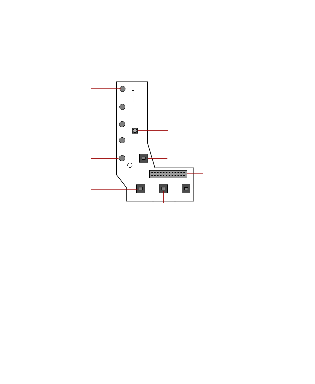
Front panel board
The front panel board supports the LEDs and buttons accessible from the front
panel. The buttons and LEDs on the front panel board are shown and
described below.
Power LED
Disk activity LED
System fault LED
PS 1 status LED
NMI button
PS 2 status LED
System reset button
Power LED glows green whenever the system is turned on. The LED also
flashes when the system is in sleep mode.
Disk activity LED glows green whenever a hard drive is actively reading or
writing data.
System fault LED (yellow) indicates ECC memory system fault (steady
indicates an uncorrectable ECC fault and blinking indicates a correctable ECC
fault).
PS 1 status LED glows green when the first power supply module in the
redundant power supply is installed and working correctly. It flashes green if
the power supply module fails or one of its power levels goes out of bounds.
If the power supply module is not installed, this LED is off.
Chassis intrusion detection switch
Front panel connector
Power supply alarm
speakerreset/System fault
LED reset switch
Power button
12 System Features

PS 2 status LED glows green when the second power supply module in the
redundant power supply is installed and working correctly. It flashes green if
the power supply module fails or one of its power levels goes out of bounds.
If the power supply module is not installed, this LED is off.
System reset button lets you reset the server if it has become nonresponsive.
Power button turns the server on and off. In an ACPI-enabled operating
system like Windows 2000, you can set the power button to enter sleep mode
rather than turning the system off.
Power supply alarm speaker reset/System fault LED reset switch disables
the power supply alarm speaker or resets the system fault LED. The alarm is
not cleared and the appropriate LED continues to glow until the failed power
supply module is replaced.
NMI (Non-Maskable Interrupt) button allows a technician to help debug
server errors.
Chassis intrusion detection switch sends a message to the system
management hardware, logging an event when the front bezel is removed.
Front panel connector connects the controls on the front panel with the
system board.
Front panel board 13

14 System Features

System Setup
Settinguptheserver
Use the instructions on the quick guide poster that came with the server to
assemble the server.
You can prepare a safer working environment before assembling the server
by following these guidelines:
■ Use a clean, flat, and stable surface for the server. Allow at least 12 inches
at the rear of the server for cabling and air circulation.
■ Obtain an adequately rated uninterruptible power supply (UPS). A UPS
protects against AC line spikes, power interruptions, and other power
fluctuations that may damage the server.
■ Protect the server from extreme temperature and humidity. Do not
expose it to direct sunlight, heater ducts, or other heat-generating objects.
■ Keep the server away from equipment that generates magnetic fields,
such as unshielded stereo speakers. Even a telephone placed too close to
the server may cause interference.
2
■ Plug the server into a wall outlet, power strip, or uninterruptible power
supply (UPS). Make sure the power cords are secured in the power supply
cable clamp on the back panel.
Important Keep the boxes and packing material. If you need to send
theserver to Gatewayforrepairs,youmust usetheoriginal
packaging or your warranty may be voided.
Settinguptheserver 15
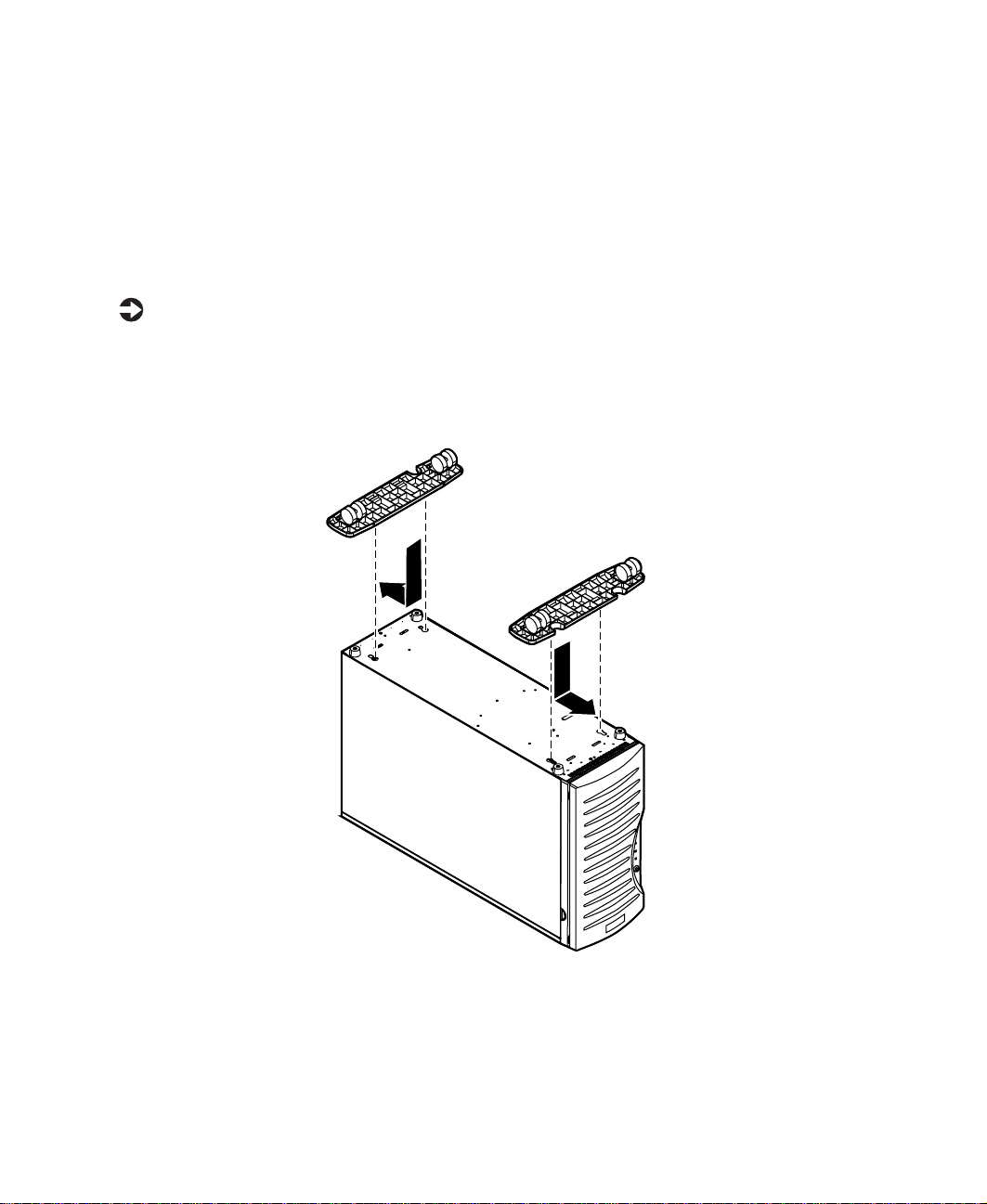
Installing the outriggers and castors
The tower chassis is shipped with small rubber feet to prevent it from slipping
and to minimize vibrations when the chassis is placed on a desktop. However,
if you intend to place the chassis on the floor, you may find it easier to
maintain the system if you install the castors (included), which let you roll
the server out for easier access.
To install the outriggers and castors:
1 Gently turn the chassis upside down, resting it on the top panel.
2 Align the outriggers and castors with the slots on the bottom panel of
the chassis.
3 Place the tabs on the outriggers into the corresponding slots on the
bottom panel and slide the outriggers toward the ends of the chassis.
4 Carefully return the chassis to the upright position.
16 System Setup

Starting the server
Before you start the server for the first time, make sure that:
■ The redundant power supply is autosensing. It automatically determines
the voltage of the incoming power source and compensates accordingly.
■ All cables are firmly connected to the proper ports on the back panel of
the server.
Caution Electricity can flow from connected peripherals into the
system causing a shock. Make sure your server and
peripherals are turned off and unplugged from the power
outlet when you connect peripherals to the server.
■ Both power supply modules in the redundant power supply are turned
on.
■ The server and monitor are plugged into an AC outlet, power strip, or
UPS (uninterruptable power supply) and that the power strip or UPS is
turned on.
To start the system:
1 If you have connected the system components to a power strip or UPS,
make sure all the system components are turned off, then turn on the
power strip or UPS.
2 Turn on the monitor.
3 Turn on the server. Make sure that the individual power buttons on the
power supply modules are turned on. The light-emitting diodes (LEDs)
on the front panel and on each power supply module are lit when the
power is on.
4 Turn on any other components connected to the server, such as speakers,
a printer, or a scanner. If nothing happens when you turn on the system:
■ Make sure that the power cables are securely plugged in and that
the power strip or UPS is plugged in and turned on.
■ Make sure that the monitor is connected to the server, plugged into
the power strip, AC outlet, or UPS, and turned on. You may also
need to adjust the brightness and contrast controls on the monitor.
Starting the server 17
Understanding the Power-OnSelf-Test
When you turn on your server, the power-on self-test (POST) routine checks
the system memory and components. To see this information on the screen,
press T
The system displays an error message if POST finds any problems. Write down
any error messages that you see. If you continue to have problems, these error
messages may help Technical Support diagnose the cause.
AB during POST.
Setting up the operating system
The first time you start your server, the operating system takes a few minutes
to set up. Refer to your operating system documentation for specific questions
regarding the operating system.
Important For other operating systems, such as Windows®2000 or
®
Novell
software manual for setup instructions.
Netware,referto the appropriate operating system
To complete the operating system setup for Windows NT:
1 After the server starts, the start-up wizard opens. Continue by clicking
Next.
2 Type the requested information in the appropriate text boxes. When you
have finished typing the information, continue by clicking
3 Continue following the instructions and selecting options in the start-up
wizard dialog boxes, clicking
the wizard tells you to restart your server.
If you need to return to the previous dialog box to change any of your
entries, click
Back.
Next to move through the dialog boxes, until
4 Restart the server. The setup is complete.
Next.
18 System Setup

Turning off the server
Every time you turn off the server, shut down the operating system first. You
may lose data if you do not follow the proper procedure.
Important For other operating systems, such as Windows 2000 or
Novell Netware, refer to the appropriate operating system
software manual for instructions.
To turn off the server in Windows NT:
1 Click Start, then select Shut down the computer?, then Shut Down.
2 Click OK. The operating system shuts down. If you see a message saying
It is now safe to turn off your computer, turn off the server by pressing the
power button.
3 Turn off the monitor and peripherals.
Warning When you turn off the serverbypressing the power button,
some electric current still flows through it. Before opening
theservercase or connecting or removing any peripherals,
turn off the server,then unplugthepowercord and modem
cord (if installed) or you may get an electric shock.
Turning off the server 19

Resetting the server
If your server does not respond to keyboard or mouse input, you may have
to close programs that are not responding. If closing unresponsive programs
does not restore your server to normal operation, you may have to reset the
system.
Important For other operating systems, such as Windows 2000 or
Novell Netware, refer to the appropriate operating system
software manual for instructions.
To close unresponsive programs and reset the server in
Windows NT:
1 Press CTRL+ALT+DEL. A window opens that lets you close a program that
is not responding.
2 Click Task Manager, then select the program that is not responding.
3 Close the program by clicking End Task.
4 If the server does not respond, press the reset button to restart the server.
As a part of the regular startup process, a program to check the disk status
runs automatically. When the checks are finished, Windows starts.
20 System Setup

Case Access
The Gateway 7400 Server is designed as a toolless chassis. None of the normal
user-serviceable parts require a tool of any kind to remove, install, or replace.
In some cases where the pieces fit very tightly, a tool may make the job easier.
The various clips, tabs, thumbscrews, and other devices that allow toolless
construction are color-coded in green for easy identification.
3
21

Preventing static electricity discharge
Before opening the server case, follow these precautions to prevent damage
from static electricity. When opening your server case, always perform the
following procedure.
Caution Static electricity can permanently damage electronic
components in your server. Prevent electrostatic damage
to your server by following static electricity precautions
every time you open your server case.
To prevent static electricity discharge:
1 Turn off the server power.
2 Touch a bare metal surface on the back of the server.
3 Unplug all power cords from AC outlets and disconnect the modem cord
(if installed).
Also follow these static electricity precautions:
■ Avoid static-causing surfaces such as plastic and packing foam in your
work area.
■ Remove the parts from their antistatic bags or containers only when you
are ready to use them. Do not lay parts on the outside of an antistatic
bag or container because only the inside provides antistatic protection.
■ Always hold cards by their edges and their metal mounting brackets.
Avoid touching components on the cards and the edge connectors that
connect to expansion slots. Never slide cards or other parts over any
surface.
22 Case Access

Opening the case
Important All references to front, back, left, or right on the server are
based on the server being in a normal, upright position,
as viewed from the front.
The only components that are accessible from outside of the chassis are the
front panel indicator lights. To access any of the removable media drives, the
hot-plug drives, or the power and reset switches you must open the bezel door.
To work on the internal components of the server, you must open the chassis,
which has two removable parts:
■ A bezel that covers the front of the chassis
■ A side cover panel that permits access to the interior of the case
Because the components inside the server are extremely sensitive to static
electricity, make sure to follow the precautions at the beginning of this chapter
for avoiding static electricity damage.
Only qualified personnel should open the system for maintenance. If you are
qualified to maintain the system yourself, make sure you are properly
grounded before opening the system chassis.
Warning Avoid exposure to dangerous electrical voltages and
movingparts byturning off your serverand unplugging the
power cord and modem cord (if installed) before removing
the side cover panel.
Opening the case 23

Opening the bezel door
The bezel door covers the removable media drives, the hot-plug drives, and
the front panel controls. To access these components, you must open the bezel
door.
To open the bezel door:
1 If the bezel door is locked, unlock it.
2 Grip the bezel door handle beside the front panel indicator lights, then
pull the door open.
Chassis lock
24 Case Access
Bezel door
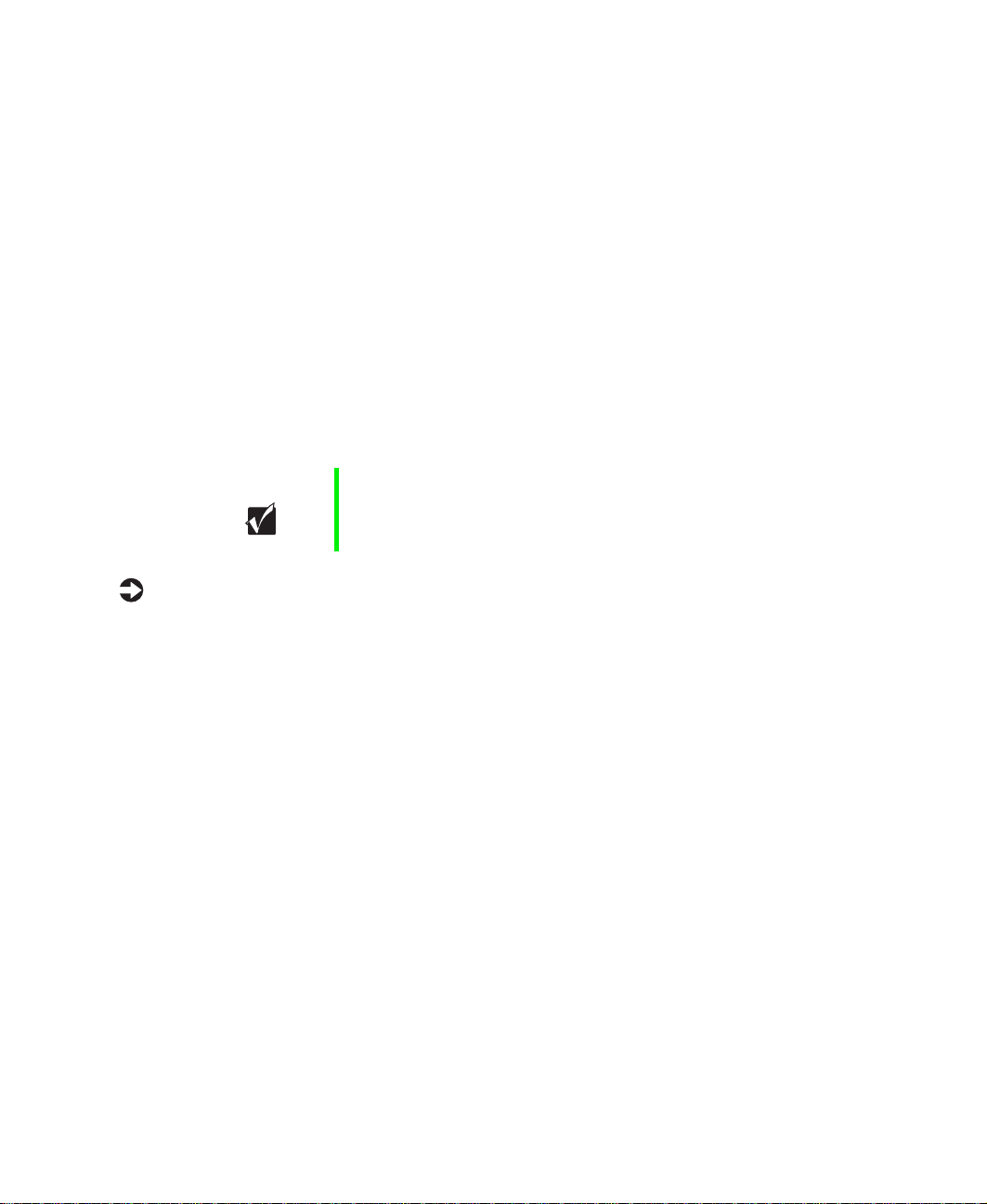
Removing the bezel
The locking bezel provides secure access to the system components. You must
unlock and remove the bezel before you can remove the side cover panel and
access the interior of the system.
To remove the bezel:
1 Turn off the system and disconnect the power cord, modem cord (if
installed), and all external peripheral devices.
2 Observe all safety and static electricity precautions. (See “Preventing static
electricity discharge” on page 22.)
3 Unlock the bezel, if it is not already unlocked.
4 Press the tabs at the sides of the bezel and pull the top of the bezel away
from the server.
5 Lift the bezel away from the chassis.
Opening the case 25
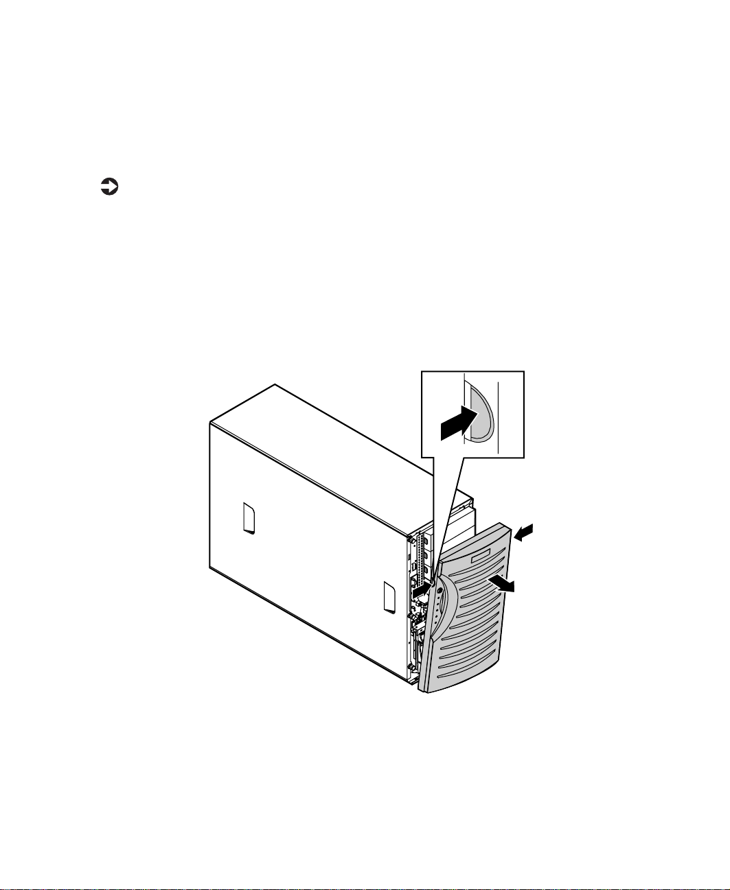
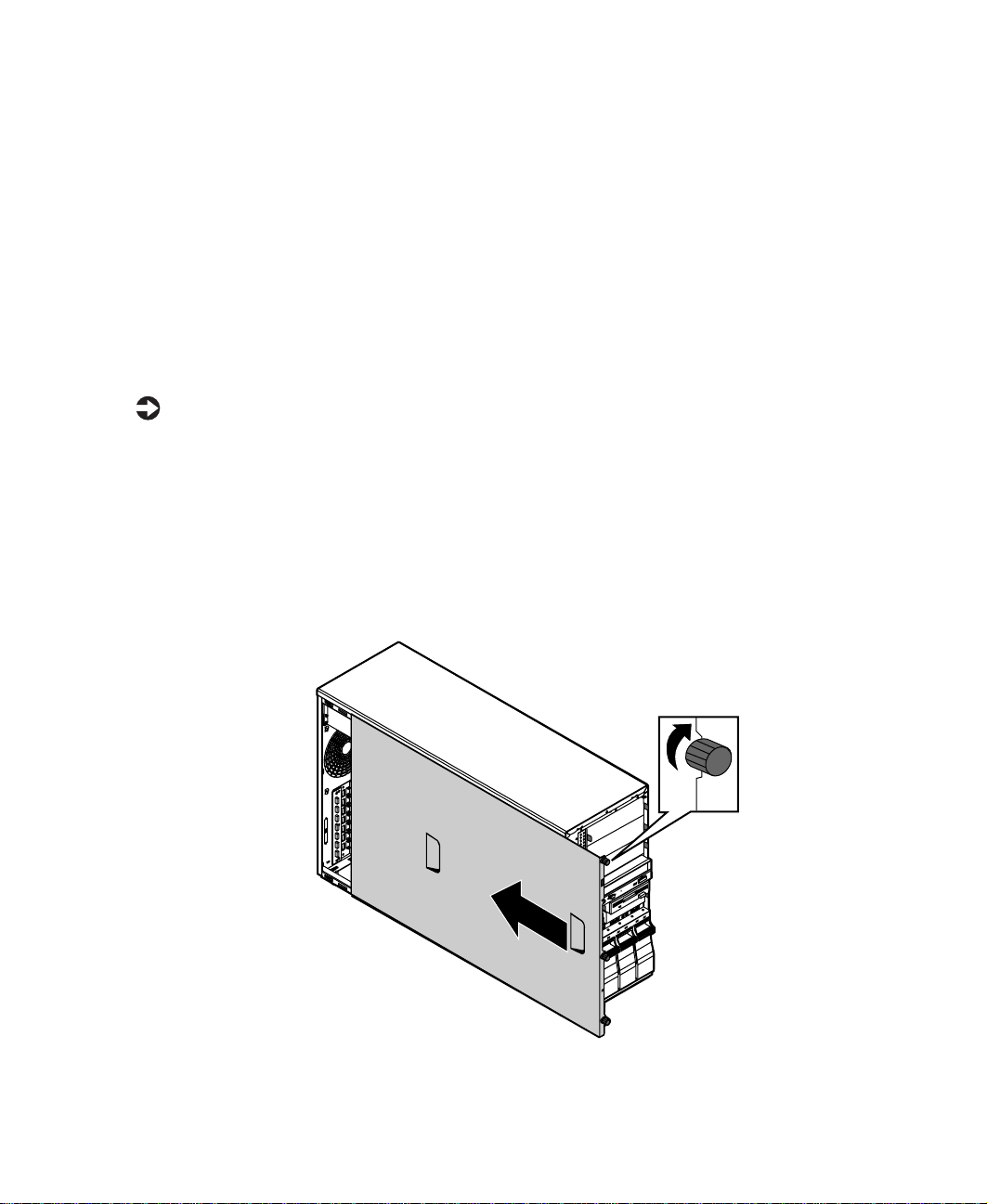
Removing the side cover panel
The side cover panel cannot be removed unless the front bezel has already
been removed. The side panel provides access to all of the internal
components of the server.
To remove the side cover panel:
1 Turn off the system and disconnect the power cord, modem cord (if
installed), and all external peripheral devices.
2 Observe all safety and static electricity precautions. (See “Preventing static
electricity discharge” on page 22.)
3 Remove the bezel. (See “Removing the bezel” on page 25.)
4 Loosen the three thumbscrews from the left side of the front panel.
5 Slide the side panel to the front, disengaging the retaining tabs on the
top edge of the panel from the top of the chassis.
6 Lift the panel out and away from the chassis.
26 Case Access
Thumbscrew
Closing the case
Close the chassis as soon as you finish installing or removing components
so that dust and dirt do not collect inside the server.
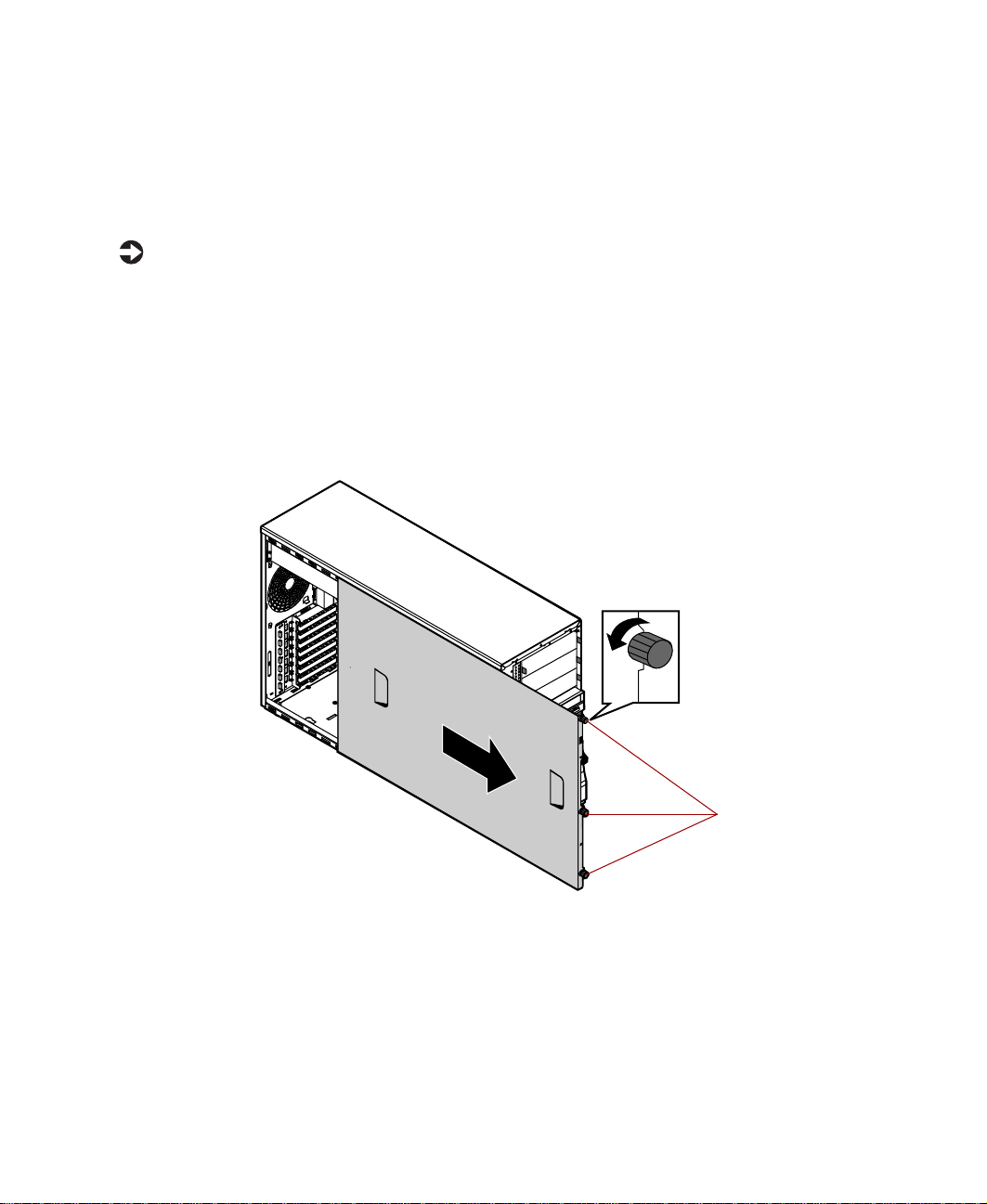
Replacing the side panel
Closing the side panel covers the internal components. You must close the
side panel and replace the front bezel before you can operate the server. If
you do not, a system intrusion event is logged by the system management
hardware. Be careful not to pinch any cables with the panel as you replace it.
To replace the side panel:
1 Hold the side panel 3/4-inches forward of the chassis. Engage the
retaining tabs on the bottom edge of the panel with the slots at the
bottom edge of the chassis.
2 Swing the top of the panel toward the chassis, engaging the retaining
tabs on the top edge of the side panel with the slots on the chassis.
3 Slide the panel toward the back of the chassis 3/4-inch, securing it in
place, then tighten the thumbscrews.
Closing the case 27

Replacing the bezel
Once the side panel is in place, you must replace the bezel to operate the
server. If the server is run without the bezel installed, a chassis intrusion event
is logged by the system management hardware.
To replace the bezel:
1 Holding the bezel at an angle to the front of the chassis, place the hinge
slot on the bottom of the bezel over the flange on the bottom edge of
the chassis.
2 Swing the top of the bezel toward the chassis until the retaining tabs snap
into place.
3 Lock the bezel, if necessary.
28 Case Access

Replacing and Adding System Components
The Gateway 7400 Server is designed as a toolless chassis. None of the normal
user-serviceable parts require a tool of any kind to remove, install, or replace.
In some cases where the pieces fit very tightly, a tool may make the job easier.
The various clips, tabs, thumbscrews, and other devices that allow toolless
construction are color-coded in green for easy identification.
4
29

Drives
You can install several types of drives and similar devices in the server. All
drives are easy to install and require no tools to replace, unless you are
installing a 3.5-inch drive in a 5.25-inch drive bay.
Preparing to replace or add a drive
One 3.5-inch diskette drive, one 3.5-inch hot-plug hard drive, and one CD
drive are included with the server. You can add drives of the following types:
■ 1-inch high, 3.5-inch hot-plug drives.
■ Half-height 3.5-inch hard drives - The system board has two IDE
connectors that support as many as two drives each. IDE drives include
the IDE CD drive.
■ Half-height 5.25-inch devices.
As you prepare to install drives, keep the following in mind:
■ If you remove a drive, place it in an antistatic bag or container.
■ Before you install a drive, see the drive’s documentation for information
on configuring the drive, setting any jumpers on the drive, and attaching
cables to the drive.
■ If you are installing a drive that uses an add-in controller card, install it
before you install the drive.
■ IDE hard drives can be configured as single, master, or slave. IDE
CD drives can be configured as master or slave. Configure the drives by
using the drive-select jumpers located on the drives.
■ If only one drive is attached to a controller cable, configure the drive as
single if it is a hard drive or master if it is a CD-ROM drive. If two drives
of any type are attached to the cable, configure one as master and one
as slave.
■ You may need to configure the drives you install using the BIOS Setup
utility. Select F1 at start up to open the BIOS Setup utility.
30 Replacing and Adding System Components

Drive cabling information
Your system includes three different types of drive cables and possibly one
additional cable, if required for the options ordered. Each drive cable is clearly
labeled, indicating the cable type and showing which end to connect to the
appropriate connector on the system board and which end to connect to the
drive.
■ Use the diskette drive connector cable to connect the diskette drive.
■ Use the standard IDE connector cable to connect IDE devices such as
CD drives and standard IDE hard drives.
■ Use the SCSI LVD cable (2 connectors) to connect the hot-plug backplane
to the integrated SCSI controller on the system board or to an add-on
SCSI controller card.
■ Use the SCSI LVD cable (5 connectors with built-in terminator) to connect
optional SCSI devices to the integrated SCSI controller on the system
board or to an add-on SCSI controller card. (This cable is optional.)
Replacing the diskette drive
The diskette drive is near the bottom of the stack of drive bays.
To replace the diskette drive:
1 Turn off the system and disconnect the power cord, modem cord (if
installed), and all external peripheral devices.
2 Observe all safety and static electricity precautions. (See “Preventing static
electricity discharge” on page 22.)
3 Remove the bezel. (See “Removing the bezel” on page 25.)
4 Remove the left side cover panel. (See “Removing the side cover panel”
on page 26.)
5 Locate the 3.5-inch diskette drive.
6 Remove the power and data cables from the back of the drive, noting
their locations and orientations. (You will reconnect these cables after you
install the new drive.)
Drives 31
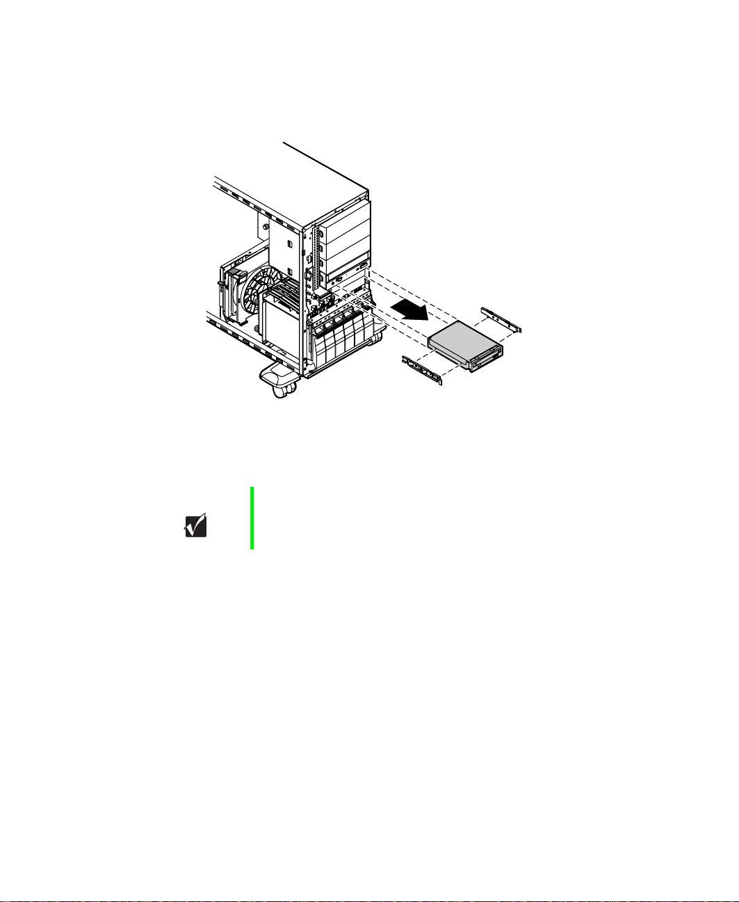
7 Disengage the rail locking tabs by pressing in on both front rail
extensions, then move the drive slightly out of the bay by pushing on
the back of the drive. Pull the drive out of the chassis.
8 Remove the rails on both sides of the drive and snap them onto the new
drive in the same positions. Make sure the front rail extensions are
towards the front of the drive.
Important The rails on the 3.5-inch diskette drive are different from
those on the hard drive and the CD drive. Make sure you
install the correct rails on each drive.
9 Set the drive jumpers to the appropriate settings (refer to your drive
documentation for jumper settings.)
10 Align the rails with the diskette drive bay, then slide the drive into the
bay until the locking tabs snap into place.
11 Connect the power and data cables, making sure the cables are in their
original positions.
12 Replace the bezel. (See “Replacing the bezel” on page 28.)
13 Close the case. (See “Closing the case” on page 27.)
14 Reconnect the power cord, the modem cord, and all other external
peripheral devices, then turn on the system.
32 Replacing and Adding System Components
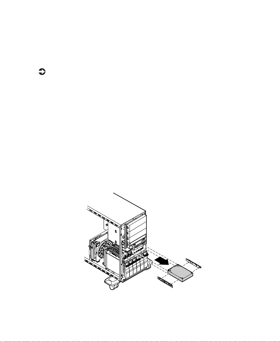
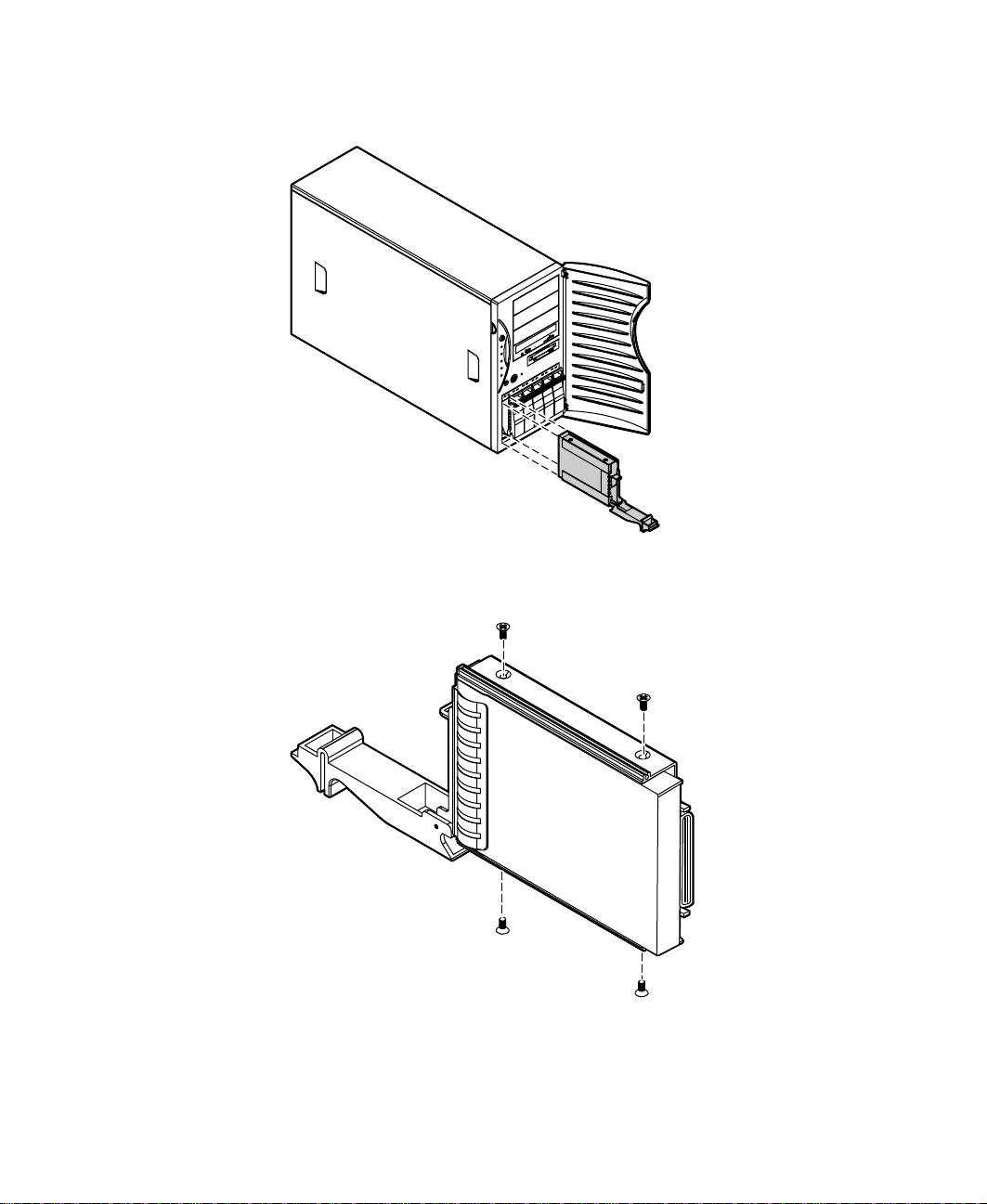
Replacing an optional drive
An optional hard drive can be shipped with the server. This drive is mounted
at the bottom of the drive stack accessible from the front of the chassis, behind
the bezel.
To replace an optional drive:
1 Turn off the system and disconnect the power cord, modem cord (if
installed), and all external peripheral devices.
2 Observe all safety and static electricity precautions. (See “Preventing static
electricity discharge” on page 22.)
3 Remove the bezel. (See “Removing the bezel” on page 25.)
4 Remove the left side cover panel. (See “Removing the side cover panel”
on page 26.)
5 Locate the 3.5-inch hard drive at the bottom of the drive stack.
6 Remove the power and data cables from the hard drive, noting their
locations and orientations (you will reconnect these cables after you
install the new drive).
7 Grip the mounting rails firmly with thumb and index finger and pull
the drive carefully straight out of the drive stack.
Drives 33

8 Remove the mounting rails from the hard drive.
9 Place the old drive in an antistatic bag or container, then place the new
hard drive on a static-free surface with the top up and the connectors
facing you.
10 Install the two drive mounting rails on the new hard drive, making sure
the front rail extensions are to the front of the device. The rails are
labeled.
11 Set the drive jumpers to the appropriate settings (refer to your drive
documentation for jumper settings.)
12 Align the rails with the open bay at the bottom of the drive stack, then
slide the drive into the stack until the locking tabs snap into place (make
sure that the data and power connectors on the drive face the inside of
the server).
13 Connect the power and data cables to the drive. (See the drive
documentation for proper cable orientation.)
14 Replace the bezel. (See “Replacing the bezel” on page 28.)
15 Close the case. (See “Closing the case” on page 27.)
16 Reconnect the power cord, the modem cord, and all other external
peripheral devices, then turn on the system.
34 Replacing and Adding System Components
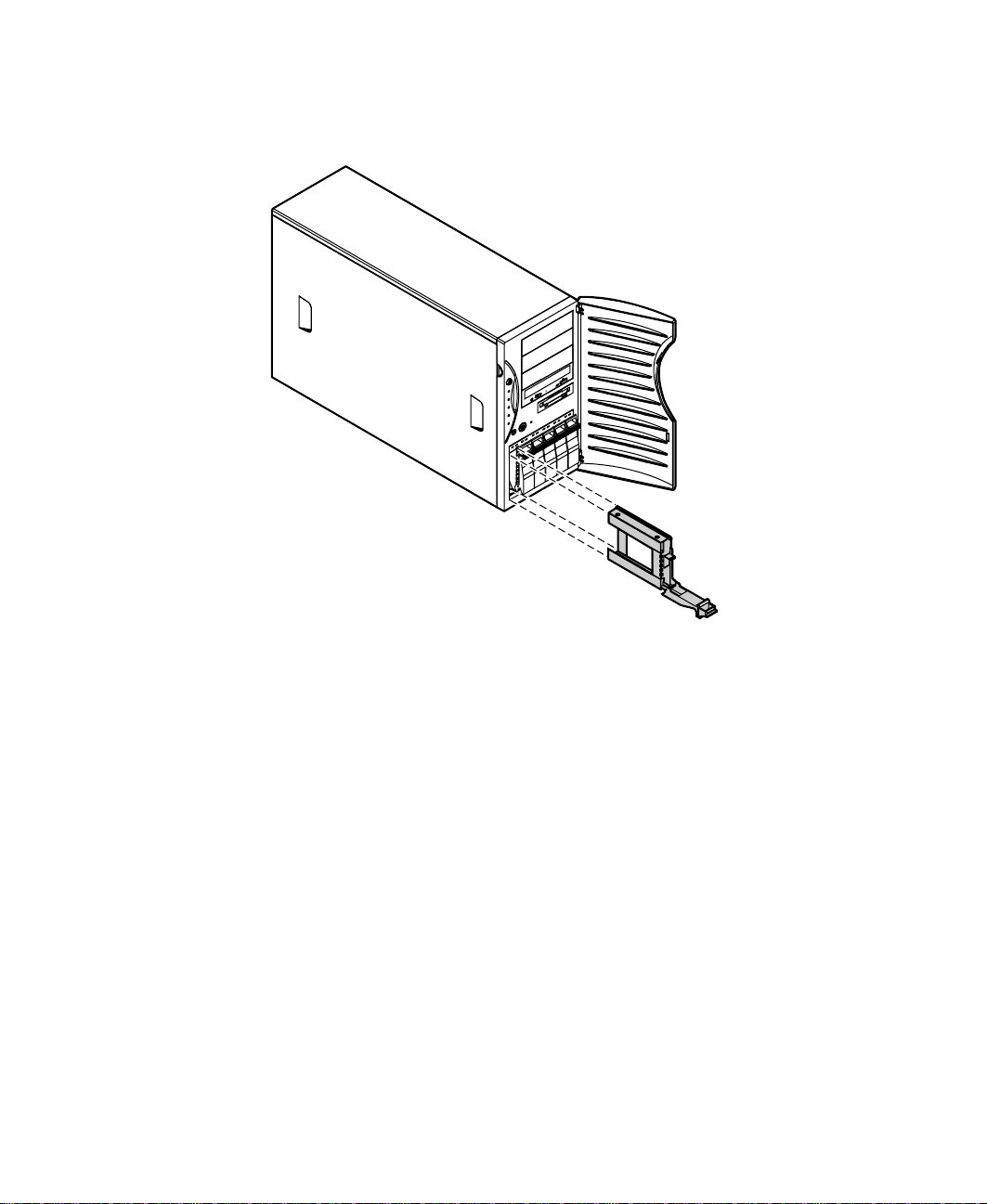
Installing a 3.5-inch drive in a 5.25-inch drive bay
Additional 3.5-inch hard drives can also be installed in the server in the empty
5.25-inch drive bays. A 5.25-inch filler tray, three of which came installed in
your server, is required for this type if installation.
To install a 3.5-inch drive in a 5.25-inch drive bay:
1 Turn off the system and disconnect the power cord, modem cord (if
installed), and all external peripheral devices.
2 Observe all safety and static electricity precautions. (See “Preventing static
electricity discharge” on page 22.)
3 Remove the bezel. (See “Removing the bezel” on page 25.)
4 Remove the left side cover panel. (See “Removing the side cover panel”
on page 26.)
5 Locate an available 5.25-inch drive bay.
6 Grip the mounting rails firmly with thumb and index finger and pull
the filler tray carefully straight out of the drive bay.
7 Leave the mounting rails on the filler tray.
Drives 35

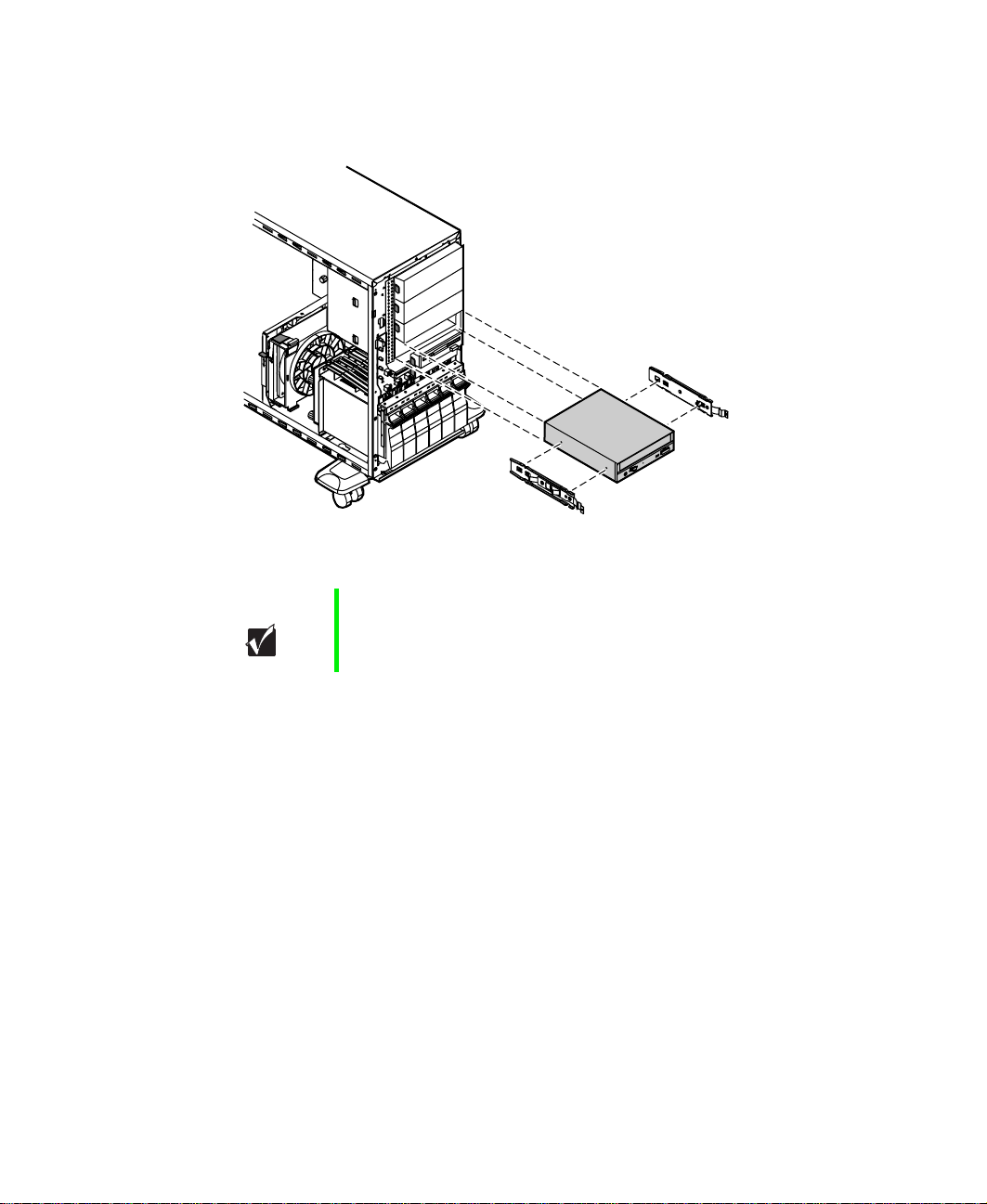
8 Remove the new hard drive from the static-free container and place it
in the filler tray with the top (label side) up and the connectors facing
away from the plastic face plate.
9 Set the drive jumpers to the appropriate settings (refer to your drive
documentation for jumper settings.)
10 Install the drive in the filler tray with four screws (6-32 x 1/4-inch Phillips
head - not provided).
36 Replacing and Adding System Components

Align the rails with the open drive bay, then slide the drive into the bay
11
until the locking tabs snap into place (make sure that the data and power
connectors on the drive face the inside of the server).
12 Connect the power and data cables to the drive. (See the drive
documentation for proper cable orientation.)
13 Replace the bezel. (See “Replacing the bezel” on page 28.)
14 Close the case. (See “Closing the case” on page 27.)
15 Reconnect the power cord, the modem cord, and all other external
peripheral devices, then turn on the system.
Drives 37

Replacing a hot-plug drive
The hot-plug drives are located at the bottom of the front panel. The hot-plug
bay supports as many as six 1-inch high 3.5-inch SCA-II SCSI hard drives.
The hot-plug drives are assigned SCSI ID numbers by the hot-plug backplane
with the drive at the far left side of the hot-plug bay assigned SCSI ID 0. The
backplane assigns SCSI IDs to the other drives in order up to SCSI ID 5 at the
far right side of the hot-plug bay.
Important Gatewaytests and verifies the operation and compatibility
of the drives it sells. Especially in a hot-plug or
mission-critical environment, additional or replacement
drives must conform to Gateway standards.
SCSI ID 0
SCSI ID 1
SCSI ID 2
SCSI ID 3
SCSI ID 4
SCSI ID 5
Install the drive in the left-most drive bay first and in increasing order by SCSI
ID number thereafter.
38 Replacing and Adding System Components

To replace a failed drive:
Caution Before you remove the failed drive, use the appropriate
software and utilities installed on the system to stop all
activity on the failed drive. Instructions for using the
software are provided by the software manufacturer.
Failure to do so may destroy the data on the drive.
1 Use the Gateway™ server management utilities to determine which drive
needs to be replaced.
2 If the drive carrier is locked, use the hex key to unlock the carrier. Locked
drive carriers show a red flag in the slot on the carrier handle.
3 Remove the drive from the drive bay by pressing down on the carrier
handle and rotating the handle out and down from the front of the server.
Drives 39
4 Continue pulling outward until the drive is entirely out of the system.
5 Remove the four screws that secure the drive to the carrier, then remove
the drive.
6 Install the new drive in the carrier using the four screws you removed
in Step 5.
40 Replacing and Adding System Components

Align the drive rails with the slots at the top and bottom of the drive bay.
7
8 Leaving the handle in the down position, push the drive all of the way
into the drive bay until the handle starts to close because of contact with
the front of the chassis.
9 Make sure the hooks on the bottom of the handle engage the edge of
the drive bay, then firmly close the handle.
10 Lock the drive carrier with the hex key.
Drives 41
Adding a hot-plug drive
The hot-plug drives are located at the bottom of the front panel. The hot-plug
bay supports up to six 1-inch high 3.5-inch SCA LVD SCSI hard drives.
The hot-plug drives are assigned SCSI ID numbers by the hot-plug backplane
with the drive at the far left side of the hot-plug bay assigned SCSI ID 0. The
backplane assigns SCSI IDs to the other drives in order up to SCSI ID 5 at the
far right side of the hot-plug bay. Install drives left to right.
SCSI ID 0
SCSI ID 1
SCSI ID 2
SCSI ID 3
SCSI ID 4
SCSI ID 5
Purchase additional SCSI drives through your Gateway sales representative.
Specify the system into which you will install the drive to ensure that the
correct drive and carrier are delivered.
Important Gatewaytests and verifies the operation and compatibility
of the drives it sells. Especially in a hot-plug or
mission-critical environment, additional or replacement
drives must conform to Gateway standards.
42 Replacing and Adding System Components

Removing an empty drive carrier
If the system ships with less than six drives installed, the empty drive bays
contain drive carriers.
If you need to replace an empty drive carrier in the system, make sure it slides
straight into place until the plastic handle begins to move upward, then close
the handle.
To remove an empty drive carrier:
1 If the drive carrier is locked, use the hex key to unlock the carrier. Locked
drive carriers show a red flag in the slot on the carrier handle.
2 Remove the drive carrier from the drive bay by pressing down on the
carrier handle and rotating the handle out and down from the front of
the server.
Drives 43
3 Continue pulling outward until the drive carrier is entirely out of the
system.
44 Replacing and Adding System Components

Installing a SCSI drive in the server
You do not need to configure individual drives before you install them in the
server.
To install a SCSI drive in the server:
1 Remove the empty drive carrier as described in “Removing an empty
drive carrier” on page 43.
2 Remove the four screws that secure the support bracket and front
assembly to the rails.
Drives 45

3 Install the drive into the carrier using the four screws you removed in
Step 2.
4 Align the drive rails with the slots at the top and bottom of the drive bay.
5 Leaving the handle down, push the drive all of the way into the drive
bay until the handle begins to close because of contact with the front
edge of the chassis.
46 Replacing and Adding System Components

Make sure the hooks on the bottom of the handle engage the edge of
6
the drive bay, then firmly close the handle.
7 Secure the drive by locking the drive carrier with the hex key.
Replacing the CD drive
The CD drive is located in one of the 5.25-inch drive bays at the top of the
drive stack in the front of the chassis.
To replace the CD drive:
1 Turn off the system and disconnect the power cord, modem cord (if
installed), and all external peripheral devices.
2 Observe all safety and static electricity precautions. (See “Preventing static
electricity discharge” on page 22.)
3 Remove the bezel. (See “Removing the bezel” on page 25.)
4 Remove the left side cover panel. (See “Removing the side cover panel”
on page 26.)
5 Locate the 5.25-inch CD drive.
6 Remove the power and data cables from the back of the drive, noting
their locations and orientations. (You will reconnect these cables after you
install the new drive.)
7 Disengage the rail locking tabs by pressing in on both front rail
extensions, then move the drive slightly out of the bay by pushing on
the back of the drive.
Drives 47
8 Pull the drive out of the chassis, then remove the rails on both sides of
the drive.
9 Snap the rails onto the new drive in the same positions. The rails are
labeled. Make sure the front rail extensions are to the front of the drive.
Important The rails on the CD drive are different from those on the
3.5-inch drives. Make sure you install the correct rails on
the CD drive.
10 Align the rails with the open bay, then slide the drive into the bay until
the locking tabs snap into place.
11 Connect the power and data cables, making sure the cables are in their
original positions. (See your drive documentation for proper cable
orientation.)
12 Replace the bezel. (See “Replacing the bezel” on page 28.)
13 Close the case. (See “Closing the case” on page 27.)
14 Reconnect the power cord, the modem cord, and all other external
peripheral devices, then turn on the system.
48 Replacing and Adding System Components

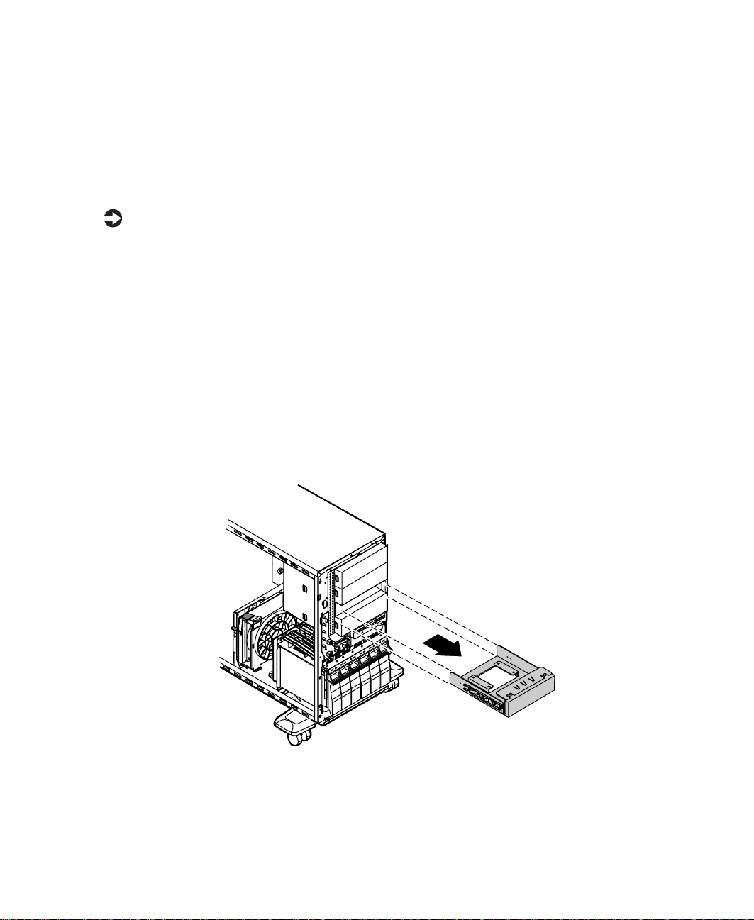
Adding additional 5.25-inch devices
You can use the three additional, externally accessible, 5.25-inch drive bays
to install additional 5.25-inch devices such as a CD writer or a tape backup
drive. Use the rails from the existing filler trays to install new drives. You may
need to purchase an additional cable of sufficient length to connect the
existing devices and the new device to the connector on the system board.
To install an additional 5.25-inch device:
1 Turn off the system and disconnect the power cord, modem cord (if
installed), and all external peripheral devices.
2 Observe all safety and static electricity precautions. (See “Preventing static
electricity discharge” on page 22.)
3 Remove the bezel. (See “Removing the bezel” on page 25.)
4 Remove the left side cover panel. (See “Removing the side cover panel”
on page 26.)
5 Remove the filler tray from the front of the drive bay by pressing in on
both front rail extensions, then move the tray slightly out of the bay by
pushing on the back of the tray.
6 Pull the drive out of the chassis.
Caution The server was designed to adhere to electromagnetic
interference requirements and the tray is an integral part
of the system. Installing an approved device should
continue to maintain those standards. If you remove the
device, you must reinstall the tray.
7 Snap the rails onto the drive, making sure the front rail extensions are
towards the front of the device. The rails are labeled.
Drives 49

8 Align the rails with the bay, and slide the drive into the chassis until the
locking tabs snap into place.
9 Connect the power and data cables, making sure the cables are in their
original positions. (See the drive documentation for proper cable
orientations.)
10 Replace the bezel. (See “Replacing the bezel” on page 28.)
11 Close the case. (See “Closing the case” on page 27.)
12 Reconnect the power cord, the modem cord, and all other external
peripheral devices, then turn on the system.
13 Run the configuration software, if necessary.
50 Replacing and Adding System Components

Replacingoraddingmemory
The Synchronous Dynamic Random Access Memory (SDRAM) Dual Inline
Memory Modules (DIMMs) supported by your system board conform to the
following standards:
■ 64 MB, 128 MB, 256 MB, and 512 MB ECC DIMMs.
■ PC133-compliant, registered, parity, ECC SDRAM.
Memory is installed in four banks (slots) on the system board. When you are
selecting and installing DIMMs, keep the following in mind:
■ Registered DIMMs should not be combined with unbuffered DIMMs.
■ Memory must be installed in reverse order, from right to left (from
bank 3, through bank 0).
■ No jumper settings are required for the memory size or type because the
BIOS automatically detects this information.
■ 2 GB maximum system memory.
To replace DIMMs:
1 Turn off the system and disconnect the power cord, modem cord (if
installed), and all external peripheral devices.
2 Observe all safety and static electricity precautions. (See “Preventing static
electricity discharge” on page 22.)
3 Remove the bezel. (See “Removing the bezel” on page 25.)
4 Remove the left side cover panel. (See “Removing the side cover panel”
on page 26.)
Replacing or adding memory 51

5 Pull open the socket latches on each side of the DIMM socket, then lift
the DIMM out of the socket. Store the DIMM in an anti-static container.
6 Insert the new DIMM into the socket and align the two notches in the
DIMM with the two notches in the DIMM socket.
7 Gently press the DIMM into the socket until it is firmly seated. Inserting
the DIMM automatically locks the socket latches on each end of the
DIMM.
8 Replace the bezel. (See “Replacing the bezel” on page 28.)
9 Close the case. (See “Closing the case” on page 27.)
10 Reconnect the power cord, the modem cord, and all other peripherals,
then turn on the system.
52 Replacing and Adding System Components

To add DIMMs:
1 Turn off the system and disconnect the power cord, modem cord (if
installed), and all external peripheral devices.
2 Observe all safety and static electricity precautions. (See “Preventing static
electricity discharge” on page 22.)
3 Remove the bezel. (See “Removing the bezel” on page 25.)
4 Remove the left side cover panel. (See “Removing the side cover panel”
on page 26.)
5 Pull open the socket latches on each side of the DIMM socket.
6 Insert the new DIMM into the socket and align the two notches in the
DIMM with the two notches in the DIMM socket.
7 Gently press the DIMM into the socket until it is firmly seated. Inserting
the DIMM automatically locks the socket latches on each end of the
DIMM.
8 Replace the bezel. (See “Replacing the bezel” on page 28.)
Replacing or adding memory 53

9 Close the case. (See “Closing the case” on page 27.)
10 Reconnect the power cord, the modem cord, and all other peripherals,
then turn on the system.
54 Replacing and Adding System Components

Replacingoraddingaprocessor
The system is compatible with the Pentium®III (FC-PGA Socket 370) 667 MHz
and faster processors with 133 MHz front-side bus (FSB). As many as two
processors may be installed in the system (they must have the same processor
and FSB speed). Processor and FSB speed are automatically detected by the
system, therefore there are no system board jumpers to set.
When adding or replacing a processor, order a processor upgrade kit from
Gateway. The kit includes the processor, a heatsink, and a disposable,
antistatic wriststrap. If you are installing a faster processor, your system may
require a BIOS update to be compatible with the new processor. Voltage
Regulator Modules (VRMs) for both processors are built into the system board.
Caution A heatsink must be installed on each processor.Installing
a processor without a heatsink could result in damage to,
or failure of, the processor.
To replace the processor you must perform the following tasks:
■ Remove the heatsink
■ Remove the processor
■ Install the new processor
■ Replace the heatsink
To remove the heatsink:
1 Turn off the system and disconnect the power cord, modem cord (if
installed), and all external peripheral devices.
2 Observe all safety and static electricity precautions. (See “Preventing static
electricity discharge” on page 22.)
3 Remove the bezel. (See “Removing the bezel” on page 25.)
4 Remove the left side cover panel. (See “Removing the side cover panel”
on page 26.)
5 Disconnect the fan cable from the fan connector on the system board.
(See “System board” on page 8 for the location of the fan connector.)
Replacing or adding a processor 55
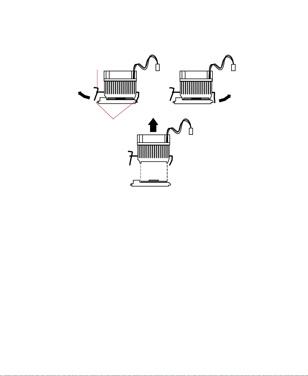
6 Unhook the metal clip from the tab on the processor socket by pressing
down on the clip and then pulling out on the clip.
Metal clip
1.
2.
3.
Tabs
7 Unhook the other end of the metal clip.
8 Lift the heatsink straight up and off the processor.
56 Replacing and Adding System Components

To remove the processor:
1 Open the locking lever on the processor socket by moving the lever
slightly out to the side and then lifting it up 90 degrees.
Locking
lever
2 Lift the old processor straight up and out of the socket.
To install the new processor:
1 Hold the new processor over the empty processor socket and verify that
pin 1 on both the processor and the socket are aligned. Pin 1 is near the
marked corner.
2 Gently place the new processor into the socket.
Processor
Pin 1
3 Secure the processor by lowering the locking lever until the lever latches
into place. The processor will slip into place without pressure when
aligned correctly.
Replacing or adding a processor 57
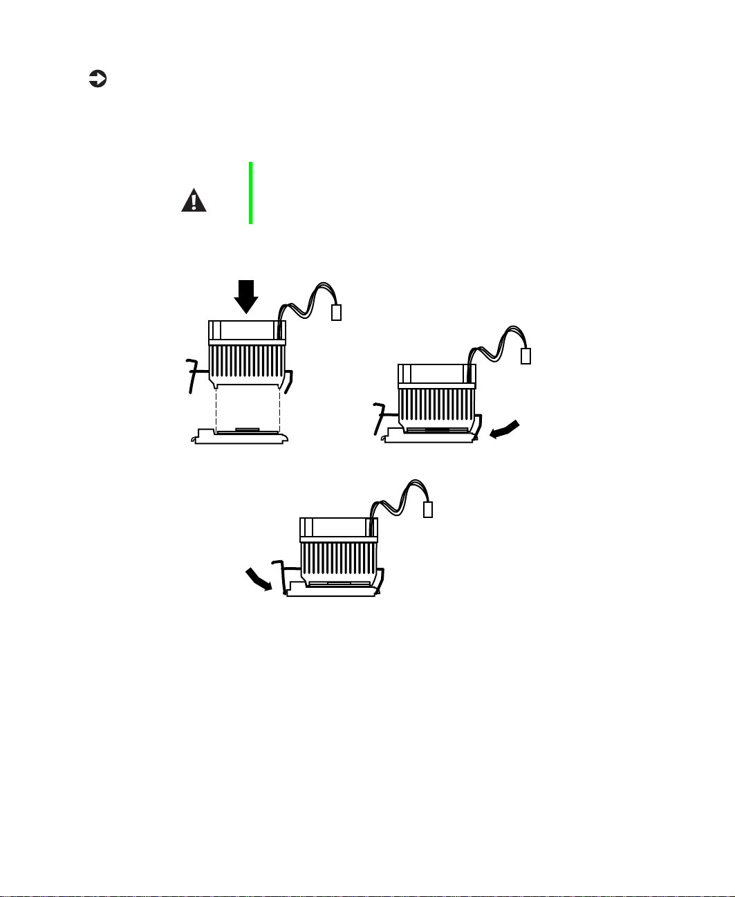
To replace the heatsink:
1 Hook the metal clip on the heatsink to the plastic tabs on the processor
socket. Make sure the heatsink is level with the processor and the metal
clips are securely attached.
Caution It is very important that the heatsink makes direct contact
with the processor orelse it willnot cool correctly,resulting
in processor failure.
1.
2.
3.
2 Connect the heatsink fan cable to the fan connector on the system board.
3 Replace the bezel. (See “Replacing the bezel” on page 28.)
4 Close the case. (See “Closing the case” on page 27 for instructions.)
5 Reconnect the cords you removed, then turn on the server.
58 Replacing and Adding System Components

To add an additional processor:
1 Turn off the system and disconnect the power cord, modem cord (if
installed), and all external peripheral devices.
2 Observe all safety and static electricity precautions. (See “Preventing static
electricity discharge” on page 22.)
3 Remove the bezel. (See “Removing the bezel” on page 25.)
4 Remove the left side cover panel. (See “Removing the side cover panel”
on page 26.)
5 Open the locking lever on the processor socket by moving the lever
slightly out to the side and then lifting it up 90 degrees.
6 Hold the new processor over the empty processor socket and verify that
pin 1 on both the processor and the socket are aligned. Pin 1 is near the
marked corner.
7 Gently place the new processor into the socket.
8 Secure the processor by lowering the locking lever until the lever latches
into place. The processor will slip into place without pressure when
aligned correctly.
9 Install the heatsink as described in “To Replace the Heatsink” on page 58.
10 Connect the power supply cable of the processor fan to the second CPU
fan connector on the system board (See “System board” on page 8 for
location).
11 Replace the bezel. (See “Replacing the bezel” on page 28.)
12 Close the case by following the instructions on page 27.
13 Reconnect the cords you removed, then turn on the server.
Replacing or adding a processor 59
Replacing the battery
The battery provides power for the system real-time clock and CMOS memory,
which holds the system configuration information.
If your battery is failing you may notice the server clock slowing down and
giving you the incorrect time.
Open the BIOS Setup utility and write down all the values in the various
menus before replacing the battery. Replacing the battery resets the BIOS Setup
utility to its default values.
Warning Danger of explosion if battery is incorrectly replaced.
Replace only with the same or equivalent type
recommended by manufacturer.
Dispose of used batteries according to manufacturer’s
instructions.
Warnung Explosionsgefahr bel falsch eingebautter batterie.
Ersetzen der batterien nur mit batterien des gleichen typs
oder mit batterien vom hersteller empfohlenen typs.
Entsorgen gebrauchter batterien entsprechned
herstellerangaben.
Attention Il y a danger d’explosion s’il y a replacement incorrect de
la batterie.
Remplacer uniquement avec une batterie du même type
ou d’un type équivalent recommandé par le constructeur.
Mettre au rebut les batteries usagées conformément aux
instructions du fabricant.
To replace the battery:
1 Restart the server and start the BIOS Setup utility by selecting F1 when
you are prompted to do so.
2 Write down the CMOS values from each tab in the BIOS Setup utility so
you can reenter them after you replace the battery. For more information
about the BIOS Setup utility. (See “About the BIOS Setup utility” on
page 85.)
60 Replacing and Adding System Components
Turn off the system and disconnect the power cord, modem cord (if
3
installed), and all external peripheral devices.
4 Observe all safety and static electricity precautions. (See “Preventing static
electricity discharge” on page 22.)
5 Remove the bezel. (See “Removing the bezel” on page 25.)
6 Remove the left side cover panel. (See “Removing the side cover panel”
on page 26.)
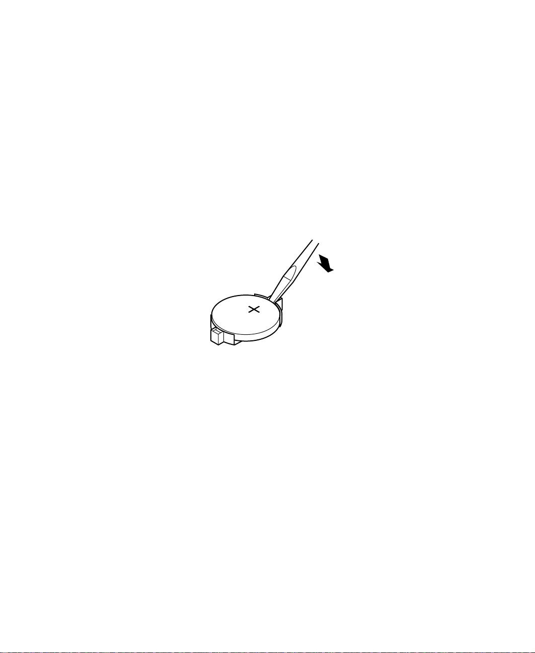
7 Locate the battery on the system board (see “System board” on page 8).
The battery is circular and has the positive pole mark (+) on the top.
8 Using a small, flat-bladed screwdriver, carefully remove the battery from
its socket on the system board.
9 Press the new battery in the socket with the positive pole up. Make sure
you have pressed the battery down far enough for it to contact the base
of the socket (it should snap into place).
10 Replace the bezel. (See “Replacing the bezel” on page 28.)
11 Close the case. (See “Closing the case” on page 27.)
12 Reconnect the power cord, the modem cord, and all other peripherals,
then turn on the system.
13 If the CMOS data is not correct, change the information in the BIOS Setup
utility using the data you recorded in Step 2.
Replacing the battery 61

Troubleshootingthe battery installation
If you have problems after installing the new battery, try each of the items
listed below:
■ Turn off the server and make sure that all exterior cables are attached
and secured to the correct connectors.
■ Make sure that all power switches are on. If the server is plugged into a
power strip, surge protector, or UPS, make sure it is turned on also.
■ Enter the BIOS Setup utility and compare the settings on the screen with
your notes or the system hardware manuals. Correct any discrepancies.
■ Turn off the server, remove the cover, and make sure that all cables inside
the case are attached securely. Also, make sure that the colored cable edges
are aligned correctly and that the connectors did not miss any pins.
Disconnect and reconnect the cables. Close the case (see “Closing the
case” on page 27), reconnect the modem and power cords, then turn on
the server.
■ Turn off the server, remove the cover and, if you have the proper test
equipment, make sure that the new battery has power. (Although
unlikely, your new battery may be defective.) Close the case (see “Closing
the case” on page 27), reconnect the power and modem cords, then turn
on the server.
62 Replacing and Adding System Components

Expansion cards
The server has seven PCI expansion slots on the system board, that may be
used for a variety of expansion cards. Two of these slots support 64-bit PCI
cards and five support 32-bit PCI cards. (See “System board” on page 8.)
Replacing an expansion card
To replace an expansion card:
1 Set any jumpers and switches on the replacement card. (See the card
instructions.)
2 Turn off the system and disconnect the power cord, modem cord (if
installed), and all external peripheral devices.
3 Observe all safety and static electricity precautions. (See “Preventing static
electricity discharge” on page 22.)
4 Remove the bezel. (See “Removing the bezel” on page 25.)
5 Remove the left side cover panel. (See “Removing the side cover panel”
on page 26.)
6 Disconnect any cables attached to the card.
Expansion cards 63
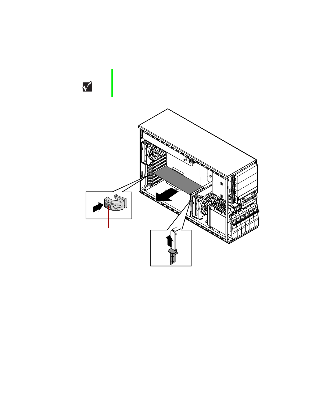
7 Remove the existing card by pressing gently on the expansion card
retention clip, sliding the retention clip back through the back panel and
pressing upwards on the card guide release tab (for full-length expansion
cards).
Important The card guide release tab is held in place during shipping
by a cotter pin. Remove the cotter pin before moving the
release tab. You can replace the cotter pin or leave it out.
Expansion card
retention clip
Card guide
release tab
8 Pull the card out of the slot.
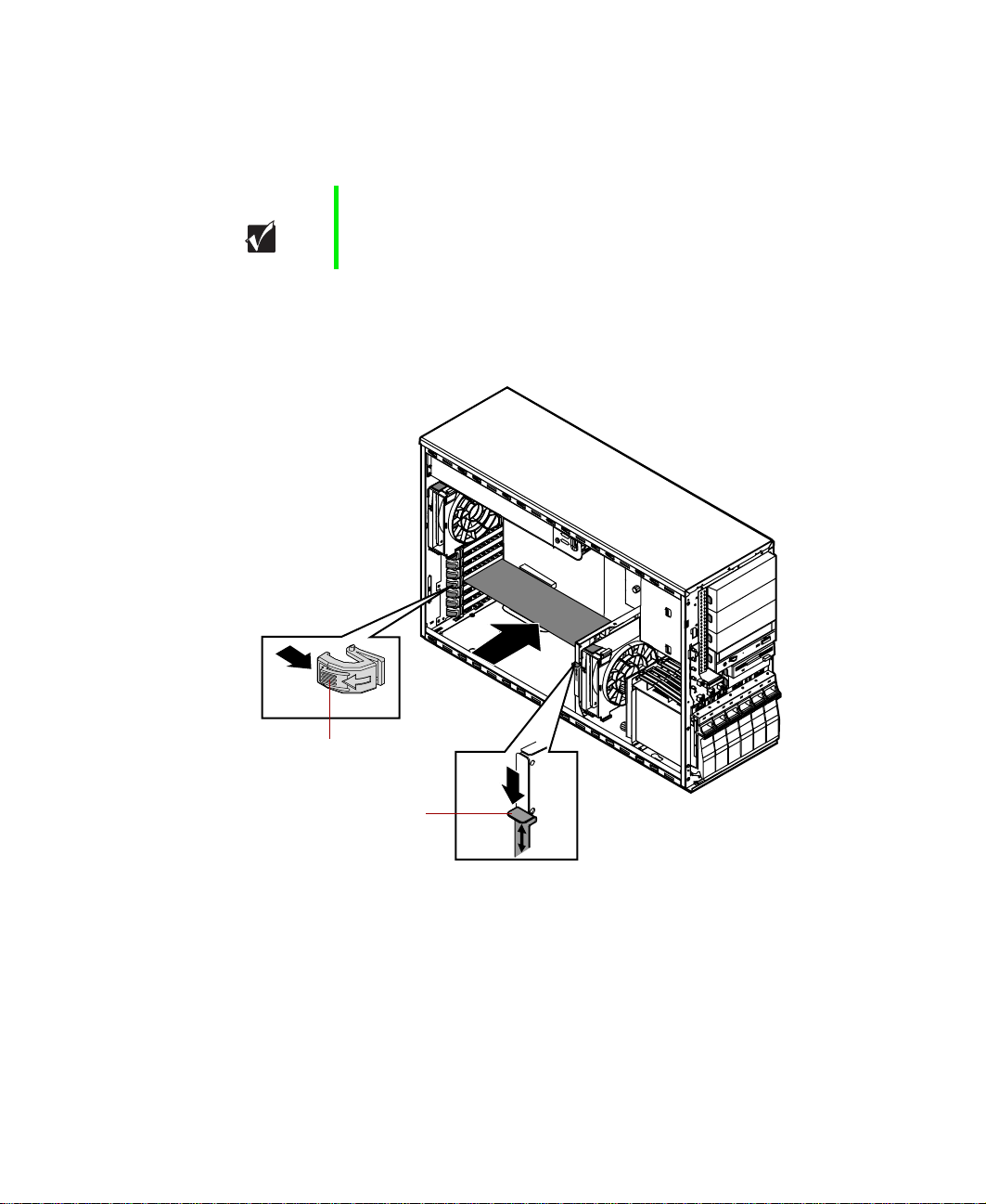
9 Insert the bottom edge of the expansion card (the keyed edge with the
contacts) into the slot on the system board and push in firmly to seat
the card.
10 Once the card is securely placed, slide the card guide release tab down
again (for full-length expansion cards) and press the expansion card
retention clip through the back panel until it clicks into place to secure
the card.
64 Replacing and Adding System Components

Connect any cables to the card (see card documentation for proper cable
11
orientation).
12 Replace the bezel. (See “Replacing the bezel” on page 28.)
13 Close the case. (See “Closing the case” on page 27.)
14 Reconnect the power cord, the modem cord, and all other peripherals,
then turn on the system.
You may need to reconfigure the server after replacing an expansion card. You
may also need to install upgrade software that came with the card. Check the
card documentation for additional information.
Adding an expansion card
To add an expansion card:
1 Set any jumpers and switches on the card according to the card
instructions, if necessary.
2 Turn off the system and disconnect the power cord, modem cord (if
installed), and all external peripheral devices.
3 Observe all safety and static electricity precautions. (See “Preventing static
electricity discharge” on page 22.)
4 Remove the bezel. (See “Removing the bezel” on page 25.)
5 Remove the left side cover panel. (See “Removing the side cover panel”
on page 26.)
6 Locate an available slot and remove the slot cover by pressing the
expansion card retention clip back through the back panel.
7 Pull out the slot cover.
Expansion cards 65
8 Press the card guide release tab upward to release the cards and allow the
new card to be inserted into the card guide (for full-length expansion
cards).
Important The card guide release tab is held in place during shipping
by a cotter pin. Remove the cotter pin before moving the
release tab. You can replace the cotter pin or leave it out.
9 Insert the bottom edge of the expansion card (the keyed edge with the
contacts) into the slot on the system board and push in firmly to seat
the card.
Expansion card
retention clip
Card guide
release tab
10 Once the card is securely placed, slide the card guide release tab down
again (for full-length expansion cards) and press the expansion card
retention clip through the back panel until it clicks into place to secure
the card.
11 Connect any cables to the card (see card documentation for proper cable
orientation).
66 Replacing and Adding System Components

Replace the bezel. (See “Replacing the bezel” on page 28.)
12
13 Close the case. (See “Closing the case” on page 27.)
14 Reconnect the power cord, the modem cord, and all other peripherals,
then turn on the system.
You may need to reconfigure the server after installing some expansion cards.
You may also need to install software that came with the card. Check the card
documentation for additional information.
Expansion cards 67

Power supplies
The Gateway 7400 Server uses a redundant power supply offering fault
tolerance and hot-swap capability. This section describes replacing the power
supply and also describes the procedure for hot-swapping a power supply
module.
Replacing a redundant power supply module
If one of the two power supply modules fails, the other module can support
the system while the failed module is replaced. An audible alarm indicates a
failed module, and the corresponding power supply status LED will begin to
flash. See “Front panel” on page 2 for the location and complete information
on the function of the power supply status LEDs. You do not have to turn
off the system to replace the failed module.
To replace a failed power supply module:
1 Determine which power supply module has failed. The module power
LED (on the back of the power supply modules) turns off when the
module fails.
2 Loosen the thumbscrew that secures the power supply module to the back
panel.
68 Replacing and Adding System Components
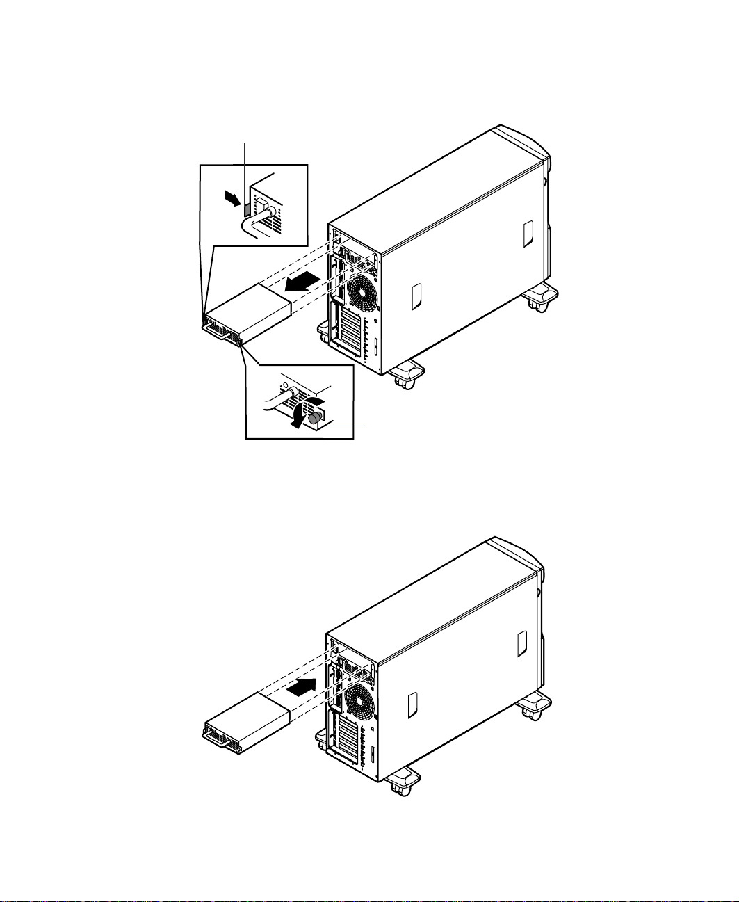
Press the locking tab toward the center of the module while carefully
3
pulling the failed module out of the power supply.
Locking tab
2
A
3
B
1
Thumbscrew
4 Carefully insert the new power supply module into the vacant slot,
pressing firmly to seat the connector at the back.
5 Tighten the thumbscrew to secure the new module in position.
A
B
Power supplies 69

Replacing the power supply
The redundant power supply offers fault tolerance and hot-swap capabilities.
However, if the power distribution board at the base of the power supply or
some other part of the power supply fails, the entire power supply and its
housing must be replaced. This type of failure is indicated by both power
supply status LEDs flashing and an audible alarm, or the system will fail to
power up.
To replace the power supply:
1 Turn off the system and disconnect the power cord, modem cord (if
installed), and all external peripheral devices.
2 Observe all safety and static electricity precautions. (See “Preventing static
electricity discharge” on page 22.)
3 Remove the bezel. (See “Removing the bezel” on page 25.)
4 Remove the left side cover panel. (See “Removing the side cover panel”
on page 26.)
5 Disconnect the power supply connectors from all internal devices,
including the 3.5-inch diskette drive, the CD drive, and all hard drives.
Make a note of where everything is connected.
6 Disconnect the main power supply connector from the system board by
pressing on the tab to release the connector, then gently pulling the
connector from the board.
70 Replacing and Adding System Components
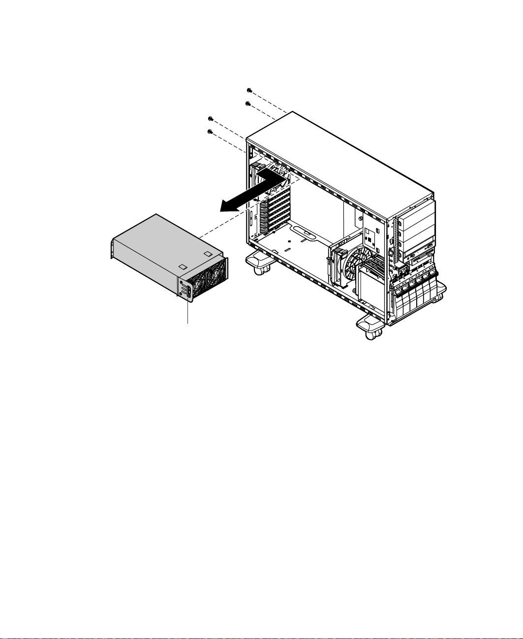
While supporting the power supply by the handle with one hand, remove
7
the screws securing the power supply to the back panel.
Handle
8 Carefully lift the power supply out of the chassis using the handle
attached to the power supply. Move the power supply forward to clear
the support bracket, then tilt the left side of the power supply down to
clear the side cover mounting rail as you pull it out.
9 Make sure that the new power supply matches the one you removed. The
mounting holes should line up correctly, and the specifications and
power output connectors should be the same.
Power supplies 71

10 Place the new power supply in the proper position in the chassis and line
up the mounting holes with the holes in the chassis.
Handle
11 Replace the screws securing the power supply to the back panel.
12 Reconnect the power connectors to the system board and to all internal
devices.
13 Replace the bezel. (See “Replacing the bezel” on page 28.)
14 Close the case. (See “Closing the case” on page 27.)
15 Reconnect the power cord, the modem cord, and all external peripherals,
then turn on the system.
72 Replacing and Adding System Components
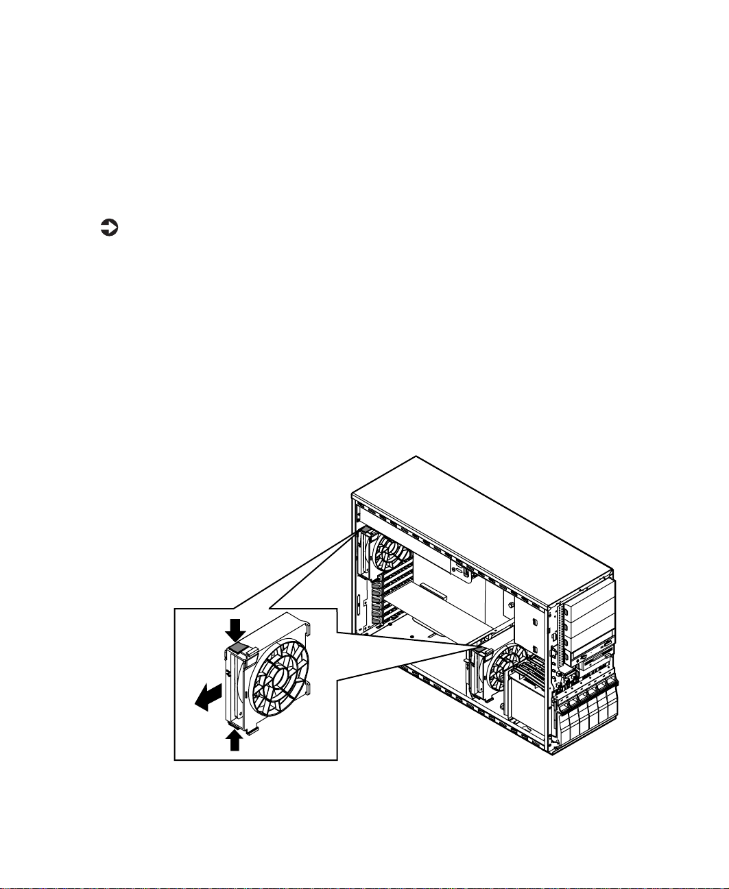
Replacing the back panel and drive cage fans
The back panel fan is located below the power supply on the back panel. The
drive cage fan is located behind the hot-plug drive cage, between the cage
and the system board. (See the illustration on page 6 for more information.)
To remove the back panel or hot-plug cage fan:
1 Turn off the system and disconnect the power cord, modem cord (if
installed), and all external peripheral devices.
2 Observe all safety and static electricity precautions. (See “Preventing static
electricity discharge” on page 22.)
3 Remove the bezel. (See “Removing the bezel” on page 25.)
4 Remove the left side cover panel. (See “Removing the side cover panel”
on page 26.)
5 Depress the two locking tabs on the fan bracket, then disengage the two
retaining tabs from either the back panel or the hot-plug drive cage.
Replacing the back panel and drive cage fans 73

6 Carefully remove the fan from the chassis.
7 Disconnect the fan power cable from the connector on the system board.
Note where the connector was attached.
8 Place the new fan bracket unit into the chassis by engaging the two
retaining tabs with the tabs on the back panel or the hot-plug cage and
the release tabs with the appropriate slots.
9 Connect the fan power cable to the appropriate connector on the system
board.
10 Replace the bezel. (See “Replacing the bezel” on page 28.)
11 Close the case. (See “Closing the case” on page 27.)
12 Reconnect the power cord, the modem cord, and all other peripherals,
then turn on the system.
74 Replacing and Adding System Components
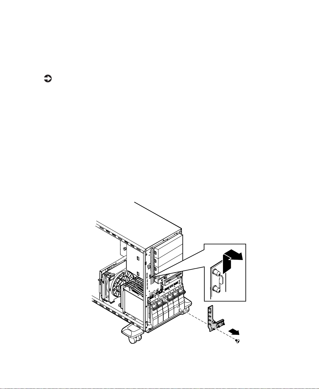
Replacing the control panel board
The control panel board is mounted on the front of the chassis, behind the
bezel.
To replace the control panel board:
1 Turn off the system and disconnect the power cord, modem cord (if
installed), and all external peripheral devices.
2 Observe all safety and static electricity precautions. (See “Preventing static
electricity discharge” on page 22.)
3 Remove the bezel. (See “Removing the bezel” on page 25.)
4 Remove the left side cover panel. (See “Removing the side cover panel”
on page 26.)
5 Disconnect the front panel connector from the control panel board.
6 Remove the screw that secures the board to the front of the chassis.
7 Lift the control panel board off of the hooks on the front panel, then
remove it.
Replacing the control panel board 75

8 Install the new control panel board by placing the mounting slots of the
control panel board on the tabs on the front of the chassis, then slide
the board down until it locks into place. Make sure the front panel cable
is out of the way as you install the board.
9 Replace the screw you removed in Step 4.
10 Plug the control panel cable into the connector on the control panel
board.
11 Replace the bezel. (See “Replacing the bezel” on page 28.)
12 Close the case. (See “Closing the case” on page 27.)
13 Reconnect the power cord, the modem cord, and all other peripherals,
then turn on the system.
76 Replacing and Adding System Components

Replacing the SCSI backplane
The six drive SCSI backplane is at the back of the drive cage. The backplane
supports as many as six hot-pluggable LVD SCSI drives. The backplane
provides activity LEDs for each drive.
To replace the SCSI backplane:
1 Turn off the system and disconnect the power cord, modem cord (if
installed), and all external peripheral devices.
2 Observe all safety and static electricity precautions. (See “Preventing static
electricity discharge” on page 22.)
3 Remove the bezel. (See “Removing the bezel” on page 25.)
4 Remove the left side cover panel. (See “Removing the side cover panel”
on page 26.)
5 Disconnect all cables to the hot-plug backplane, noting the connector
locations so you can reconnect them after replacing the backplane.
6 Remove all hot-plug drives, being careful to note which drive was in
which slot.
Replacing the SCSI backplane 77
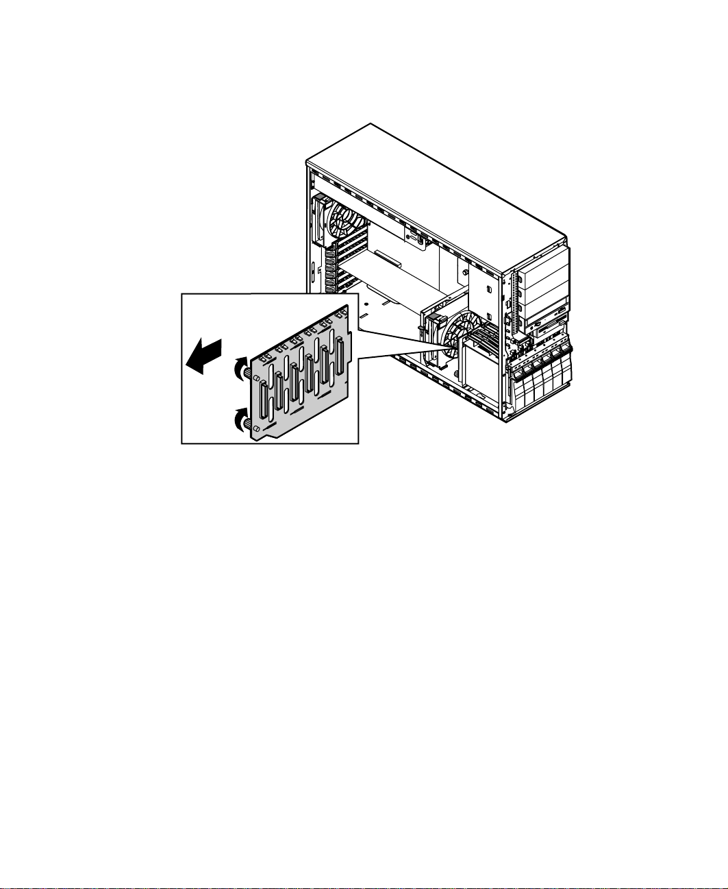
7 Loosen the two captive thumbscrews that secure the backplane in the
hot-plug cage bracket.
8 Pull the backplane out to the side of the chassis, then toward the back
of the system to remove it from the retention hooks.
9 Lift the backplane out of the chassis.
10 Set any jumpers on the new backplane that are required for your hot-plug
configuration. (See “SCSI backplane board” on page 10 for instructions.)
78 Replacing and Adding System Components

Place the backplane onto the hot-plug cage bracket, making sure the
11
hooks on the bracket fit into the slots on the backplane.
12 When the backplane is securely in place, tighten the two captive
thumbscrews.
13 Reconnect all cables on the backplane to the correct connectors.
14 Replace all hot-plug drives. Be careful to replace them in the same slots
that they were in before you removed them.
15 Replace the bezel. (See “Replacing the bezel” on page 28.)
16 Close the case. (See “Closing the case” on page 27.)
17 Reconnect the power cord, the modem cord, and all other peripherals,
then turn on the system.
Replacing the SCSI backplane 79

Replacing the system board
The system board integrates the other elements of the system, such as the
processor, memory, storage, networking, and communications, and lets them
operate in a coordinated and useful way.
Important All references to front, rear, left, or right on the server are
based on the server being in a normal, upright position,
as viewed from the front.
To replace the system board:
1 Turn off the system and disconnect the power cord, modem cord (if
installed), and all external peripheral devices.
2 Observe all safety and static electricity precautions. (See “Preventing static
electricity discharge” on page 22.)
3 Remove the bezel. (See “Removing the bezel” on page 25.)
4 Remove the left side cover panel. (See “Removing the side cover panel”
on page 26.)
5 Place the chassis gently on its right side.
6 Remove all expansion cards from the system. (See “Replacing an
expansion card” on page 63.)
7 Remove the back panel fan (see “Replacing the back panel and drive cage
fans” on page 73.)
8 Disconnect all cables from the system board, including the power cables
from the power supply, noting their locations and orientations (you will
reconnect these cables after you install the new system board).
80 Replacing and Adding System Components
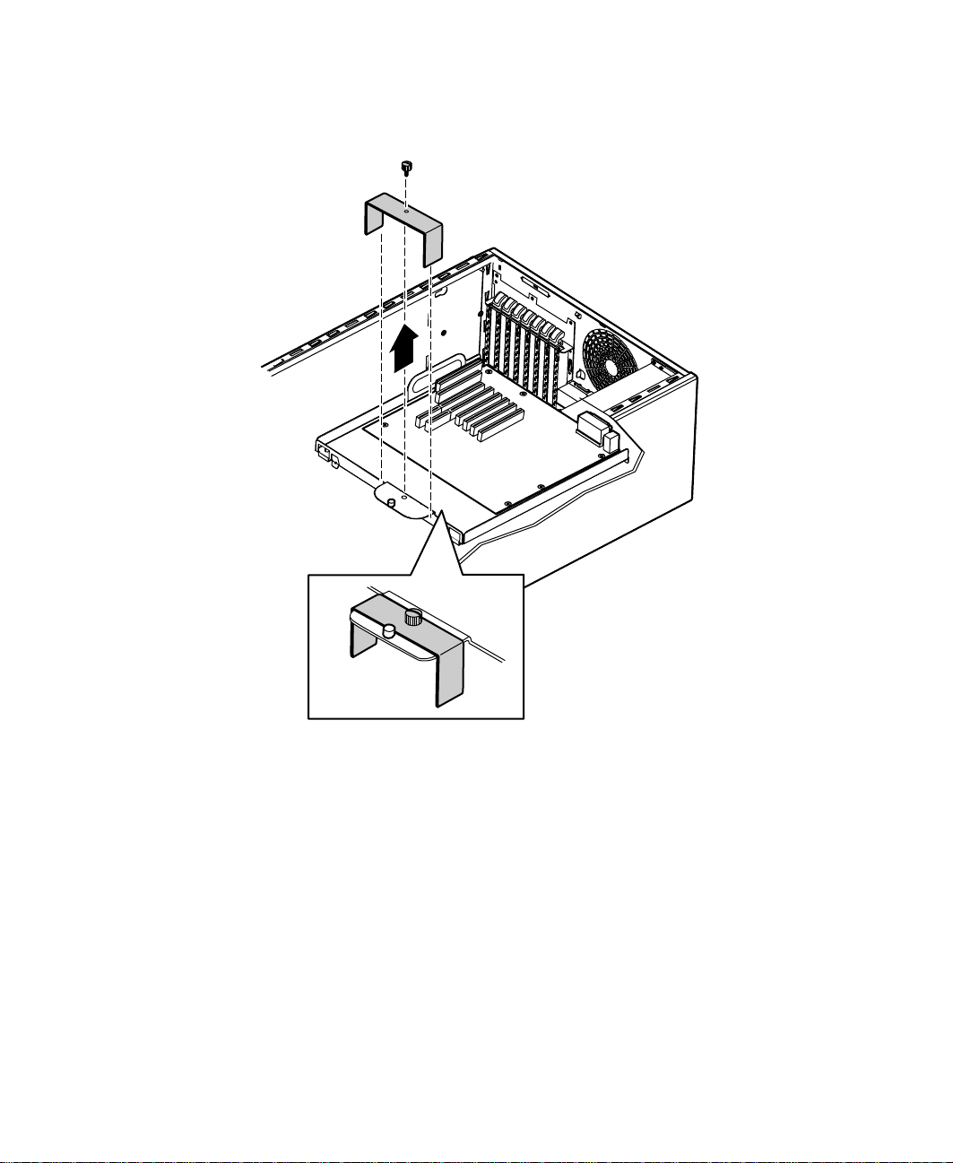
Remove the thumbscrew from the system board retaining bracket (if your
9
system is so equipped), and lift the bracket from the board support tray.
Replacing the system board 81
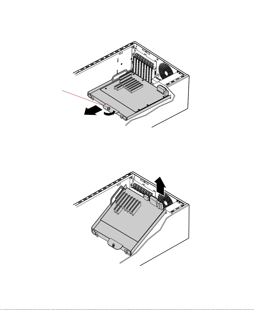
10 Loosen the retaining thumbscrew securing the board support tray to the
right side of the chassis.
Retaining
thumbscrew
11 Slide the board support tray toward the front of the chassis slightly to
disengage it from the stand-off retention hooks.
12 Using the handle at the bottom of the board support tray, pull the back
edge of the system board (the edge against the back panel) out of the
chassis.
82 Replacing and Adding System Components
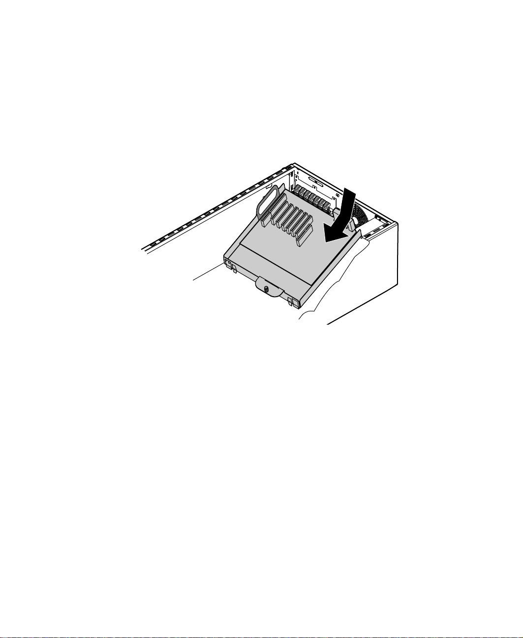
Remove the ten screws securing the system board to the support tray and
13
remove the board, then place it in an anti-static bag or container.
14 Install the replacement system board on the tray using the screws you
previously removed.
15 Holding the board support tray by the handles, place it in the chassis,
right edge first. Arrange the cables carefully to prevent tangling as you
install the board and tray assembly.
16 Holding the board support tray in place, tighten the retaining
thumbscrew on the right edge of the board support tray.
17 Replace the system board retaining bracket (if your system is so equipped)
and reinstall the retaining bracket thumbscrew.
18 Replace the back panel fan (see “Replacing the back panel and drive cage
fans” on page 73.)
19 Replace any expansion cards that you removed in Step 4 (see “Replacing
an expansion card” on page 63.)
20 Reconnect all cables on the system board to the correct connectors.
21 Return the chassis to an upright position.
22 Replace the bezel. (See “Replacing the bezel” on page 28.)
23 Close the case. (See “Closing the case” on page 27.)
24 Reconnect the power cord, the modem cord, and all other peripherals,
then turn on the system.
Replacing the system board 83

84 Replacing and Adding System Components

Using the BIOS Setup Utility
About the BIOS Setup utility
The server’s BIOS has a built-in setup utility that lets you configure several
basic system characteristics. The settings are stored in battery-backed RAM and
are retained even when the power is off.
Open the BIOS Setup utility by restarting the server, then pressing F1 when
the Gateway logo screen appears during startup. The Main BIOS Setup utility
screen opens. It may not look exactly like the screen shown below.
BIOS Setup Utility
Main Advanced Power Boot Security Exit
AMI BIOS Version :
BIOS Build Date :
BIOS ID :
Processor Type :
Processor Speed :
System Memory :
System Time :
System Date :
XX.XX.XX
XX/XX/XX
XXXXXXXX
Pentium III(tm)
800MHz
128 MB
[XX:XX:XX]
[Thu XX/XX/XXXX]
←→ Select Screen
↑↓ Select Item
-+ Change Field
Tab Select Field
F1 General Help
F10 Save & Exit
ESC Exit
5
About the BIOS Setup utility 85

As you select items on the Main menu or in submenus, you see specific
information related to the current selection in the Item Specific Help box.
The command bar shows the keystrokes necessary to access help, navigate
through the menus, and perform other functions.
■ F1 opens the Help screen, providing general help for using the BIOS Setup
utility.
■ The ↑ (up arrow) and ↓ (down arrow) keys select items in the menu.
■ The ← (left arrow) and → (right arrow) keys move you between the
menus.
■ ENTER either moves you to a submenu screen when a selected item is
preceded by > or activates a selected field.
■ ESC closes the screen you are in and returns you to the previous screen
or opens a dialog box allowing you to exit from the BIOS Setup utility.
■ F10 opens a screen that lets you save all settings, then exit the BIOS Setup
utility.
The main screen has the following menu selections at the top of the screen:
■ Main gives you access to basic information and settings related to your
system hardware and configuration.
■ Advanced gives you access to information and settings for system
resources, hardware, and system configuration.
■ Power gives you access to information and settings for power
management features.
■ Boot gives you access to information and settings for boot features and
boot sequences.
■ Security gives you access to settings related to system access passwords
and security settings (See “System security” on page 98).
■ Exit gives you access to options for exiting the BIOS Setup utility.
Refer to the Help box on the right side of the BIOS Setup screens for
information about menu items.
86 Using the BIOS Setup Utility

Updating the BIOS
If you need a new version of the BIOS, you can download the BIOS update
from Technical Support area on the Gateway Web site
(www.gatewayatwork.com) and install the new version from a diskette.
To update the BIOS you need to perform the following tasks in sequence:
■ Create a bootable diskette
■ Note the current BIOS settings
■ Create the BIOS update diskette
■ Update the BIOS
■ Restore the BIOS settings
Follow the detailed instructions for updating the BIOS that are included in
the self-extracting file that you can download from the Technical Support area
of Gateway’s Web site.
Important To add BIOS support for faster processors, you may need
to update the BIOS. If you do not receive the messages
“AP microcode OK” and “BSP microcode OK” during the
boot sequence, you will need to update the BIOS.
Updating the BIOS 87

Setting the configuration switches
The system board has a configuration switch block related to the BIOS. You
can use specific switches to reset the CMOS settings to the BIOS defaults, or
to erase a misplaced or forgotten password. For the location of the
configuration switch block, see “System board” on page 8.
Caution Moving any of these switches while the power is on can
damage your server. Alwaysturn off the server and unplug
the power cord from the server before changing switch
settings.
The Clear Passwordswitch
The Clear Password switch on the system board (SW3) lets you clear the
existing system passwords in case they are misplaced or forgotten, or if the
system administrator is unavailable. For normal operation, SW3 should be set
to the OFF position. To clear the passwords, SW3 should be set to the ON
position.
Once the switch is set to the ON position, passwords will be disabled, allowing
you to go directly to the operating system or to enter the BIOS Setup without
entering a password. To set up a new password, enter the BIOS Setup and enter
the password as you normally would, then turn off the system. Prior to turning
on the system again, open the system, return SW3 back to the OFF position,
then close the system. Make sure you turn off the server and unplug the power
cord before moving the switch.
88 Using the BIOS Setup Utility

The Clear CMOS switch
The Clear CMOS switch on the system board (SW4) lets you clear all BIOS
Setup settings. For normal operation, SW4 should be in the OFF position. To
clear the CMOS settings, SW4 should be turned to the ON position. Make sure
you turn off the server and unplug the power cord before moving the switch.
Once the switch is set to the ON position, the system passwords will be cleared
when the system goes through the POST routine. When this occurs, the
following error message will appear:
CMOS checksum bad
Press F1 to run Setup
Press F2 to load default values and continue
After selecting the appropriate option, enter any required information and
continue. When you turn off the system again, open the system, set the switch
back to the OFF position, then close the system.
Setting the configuration switches 89

90 Using the BIOS Setup Utility

Managing Your System
Protecting against power source problems
Surge suppressors, line conditioners, and uninterruptible power supplies can
help protect your system against power source problems.
Surge suppressors
During a power surge, the voltage level of electricity coming into your system
can increase far above normal levels and cause data loss or system damage.
Protect your server and peripherals by connecting them to a surge suppressor,
which will absorb voltage surges and prevent them from reaching your server.
When purchasing a surge suppressor:
■ Make sure the surge suppressor meets the appropriate product safety
certification for your location, such as Underwriters Laboratories (UL).
6
■ Check the maximum amount of voltage the suppressor allows to pass
through the line. The lower the voltage that the suppressor allows to pass
through, the better the protection for your system.
Protecting against power source problems 91

■ Check the energy absorption (dissipation) rating. The higher the energy
absorption rating, the better the protection for your system.
■ Check for line-conditioner capabilities. A line conditioner smooths out
some of the normal line noise (small voltage fluctuations) of an electrical
supply.
Line conditioners
A line conditioner protects your system from the small fluctuations in voltage
from an electrical supply. Most systems can handle this variation, called line
noise, without problems. However, some electrical sources include more line
noise than normal. Line noise can also be a problem if your system is located
near, or shares a circuit with, a device that causes electromagnetic interference,
such as a television or a motor.
Some surge suppressors and uninterruptible power supplies include simple
line-conditioning capabilities.
Uninterruptible power supplies
Use a standby uninterruptible power supply (UPS) to protect your server from
data loss during a total power failure. A UPS uses a battery to keep your server
running temporarily during a power failure and lets you save your work and
shut down your server. You cannot run your server for an extended period
of time while using only the UPS.
92 Managing Your System
 Loading...