

Page 1
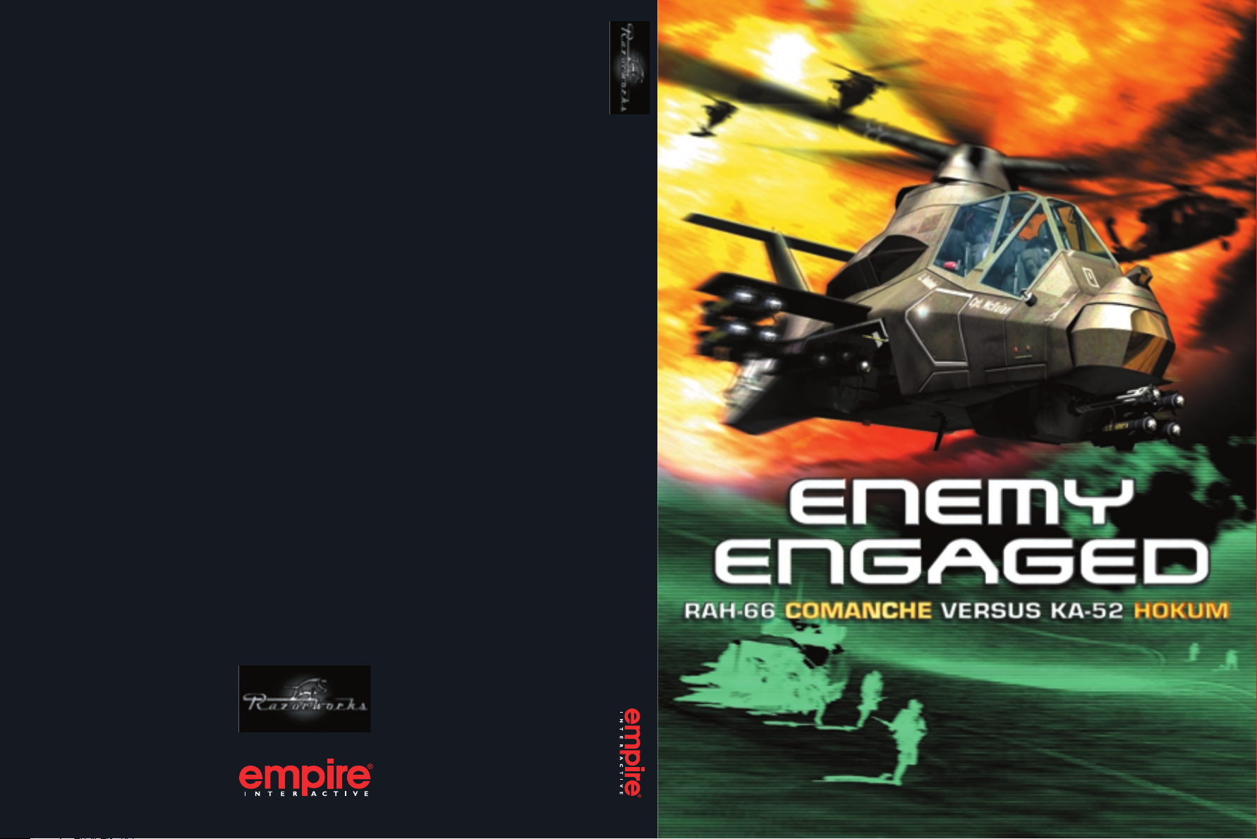
ENEMY ENGAGED - RAH-66 COMANCHE VERSUS KA-52 HOKUM
www.empireflight.com
USG-COHOKCDRUK
USER GUIDE
Page 2

DISCLAIMER
By installing, copying, or otherwise using this Software product, you agree to be bound by
the limitations set out below.
LIMITED WARRANTY
Empire Interactive warrants that the software will perform substantially in accordance with
the accompanying written materials for a period of ninety (90) days from the date of
receipt. Any implied warranties on the software are limited to ninety (90) days, unless the
effect of this clause has been specifically excluded by applicable law.
CUSTOMER REMEDIES
Empire Interactive’s entire liability and your exclusive remedy shall be, at Empire Interactive’s
option, either (a) return of the price paid, or (b) replacement of the software or hardware
that does not meet this Limited Warranty and which is returned to the place of purchase
with a copy of your receipt. This Limited Warranty is void if failure of the software has
resulted from accident, abuse, or misapplication. Any replacement software will be
warranted for the remainder of the original warranty or thirty (30) days, whichever is longer.
NO OTHER WARRANTIES
To the maximum extent permitted by applicable law, Empire Interactive and its suppliers
disclaim all other representations, warranties, conditions or other terms, either express or
implied, including, but not limited to implied warranties and/or conditions of
merchantability and fitness for a particular purpose, with regard to the software and the
accompanying written materials.
NO LIABILITY FOR CONSEQUENTIAL DAMAGES
To the maximum extent permitted by applicable law, in no event shall Empire Interactive or
its suppliers be liable for any damages whatsoever (including without limitation, direct or
indirect damages for personal injury, loss of business profits, business interruption, loss of
business information, or any other pecuniary loss) arising out of the use of or inability to
use this product, even if Empire Interactive has been advised of the possibility of such
damages. In any case, Empire Interactive’s and its suppliers’ entire liability under any
provision of this agreement shall be limited to the amount actually paid by you for the
software, unless the effect of this clause has been specifically excluded by applicable law.
This Software Licence Agreement is governed by the law of the laws of England.
ENEMY ENGAGED - RAH-66 COMANCHE VERSUS KA-52 HOKUM
TRADEMARKS OF
RIGHTS RESERVED
TRADEMARKS OF
ENTERTAINMENT INTERNATIONAL (UK) LTD . SOFTWARE ©2000 RAZORWORKS LTD. ALL
. PUBLISHED BY EMPIRE INTERACTIVE. DOLBY AND THE DOUBLE D SYMBOL ARE
DOLBY LABORATORIES LICENSING CORPORATION.
AND EMPIRE ARE
Page 3

www.razorworks.com
Page 4

i
TECHNICAL SUPPORT
If you experience any technical problems with this or any other Empire product, please
contact our technical support staff.
When you call, it helps if you have the following information to hand: computer type,
available hard disk space, total RAM, type of video card and a list of the options you choose
when you installed the game. If possible be at your computer when you call.
TECHNICAL SUPPORT: (0)20 8343 9143 10am-6pm
If you prefer to write to us, be sure to enclose the same details.
Empire Interactive
Technical Support Dept.
The Spires, 677 High Road,
North Finchley
London N12 0DA
If you have internet access and would like to contact us on-line, you will find us at:
support@empire.co.uk
Page 5

Contents
1. Introduction 1.0
Getting Started . . . . . . . . . . . . . . . . . . . . . . . . . . . . . . . . . . . . . . . . . . . . . . . . . . . . . . . . . . . . . . . . . . . . . . . 1.1
Quick Start
Strategy Guide
Updates
Compatibility With Apache Havoc
Conversion Training From Apache Havoc
2. Menu Screens 2.0
Main Screen . . . . . . . . . . . . . . . . . . . . . . . . . . . . . . . . . . . . . . . . . . . . . . . . . . . . . . . . . . . . . . . . . . . . . . . . . . . 2.1
Pilots Screen
Options Screen
Combat Screen
Session Screen
Gunship Screen
Campaign and Mission Planning Screen
3. In-Flight 3.0
Basic Handling . . . . . . . . . . . . . . . . . . . . . . . . . . . . . . . . . . . . . . . . . . . . . . . . . . . . . . . . . . . . . . . . . . . . . . . . 3.1
Missions
Radio Messages
Views
Controls
. . . . . . . . . . . . . . . . . . . . . . . . . . . . . . . . . . . . . . . . . . . . . . . . . . . . . . . . . . . . . . . . . . . . . . . . . . . . 1.2
. . . . . . . . . . . . . . . . . . . . . . . . . . . . . . . . . . . . . . . . . . . . . . . . . . . . . . . . . . . . . . . . . . . . . . . . 1.2
. . . . . . . . . . . . . . . . . . . . . . . . . . . . . . . . . . . . . . . . . . . . . . . . . . . . . . . . . . . . . . . . . . . . . . . . . . . . . . . . 1.2
. . . . . . . . . . . . . . . . . . . . . . . . . . . . . . . . . . . . . . . . . . . . . . . . . . . 1.3
. . . . . . . . . . . . . . . . . . . . . . . . . . . . . . . . . . . . . . . . . . . 1.3
. . . . . . . . . . . . . . . . . . . . . . . . . . . . . . . . . . . . . . . . . . . . . . . . . . . . . . . . . . . . . . . . . . . . . . . . . . 2.1
. . . . . . . . . . . . . . . . . . . . . . . . . . . . . . . . . . . . . . . . . . . . . . . . . . . . . . . . . . . . . . . . . . . . . . . 2.2
. . . . . . . . . . . . . . . . . . . . . . . . . . . . . . . . . . . . . . . . . . . . . . . . . . . . . . . . . . . . . . . . . . . . . . . 2.5
. . . . . . . . . . . . . . . . . . . . . . . . . . . . . . . . . . . . . . . . . . . . . . . . . . . . . . . . . . . . . . . . . . . . . . . . 2.6
. . . . . . . . . . . . . . . . . . . . . . . . . . . . . . . . . . . . . . . . . . . . . . . . . . . . . . . . . . . . . . . . . . . . . . . 2.6
. . . . . . . . . . . . . . . . . . . . . . . . . . . . . . . . . . . . . . . . . . . . . 2.7
. . . . . . . . . . . . . . . . . . . . . . . . . . . . . . . . . . . . . . . . . . . . . . . . . . . . . . . . . . . . . . . . . . . . . . . . . . . . . . . 3.5
. . . . . . . . . . . . . . . . . . . . . . . . . . . . . . . . . . . . . . . . . . . . . . . . . . . . . . . . . . . . . . . . . . . . . . . 3.8
. . . . . . . . . . . . . . . . . . . . . . . . . . . . . . . . . . . . . . . . . . . . . . . . . . . . . . . . . . . . . . . . . . . . . . . . . . . . . . . . . . 3.12
. . . . . . . . . . . . . . . . . . . . . . . . . . . . . . . . . . . . . . . . . . . . . . . . . . . . . . . . . . . . . . . . . . . . . . . . . . . . . . . 3.18
ii
4. Comanche Cockpits 4.0
Instrument Panel . . . . . . . . . . . . . . . . . . . . . . . . . . . . . . . . . . . . . . . . . . . . . . . . . . . . . . . . . . . . . . . . . . . . . . 4.2
Multi-Function Displays (MFDs)
Helmet Integrated Display and Sight System (HIDSS)
Acquiring Targets
Weapons
. . . . . . . . . . . . . . . . . . . . . . . . . . . . . . . . . . . . . . . . . . . . . . . . . . . . . . . . . . . . . . . . . . . . . . 4.19
. . . . . . . . . . . . . . . . . . . . . . . . . . . . . . . . . . . . . . . . . . . . . . . . . . . . . . . . . . . . . . . . . . . . . . . . . . . . . . . 4.30
Pilot Night Vision Sensor (PNVS)
. . . . . . . . . . . . . . . . . . . . . . . . . . . . . . . . . . . . . . . . . . . . . . . . . . . . . 4.5
. . . . . . . . . . . . . . . . . . . . . . . . . . . . . 4.16
. . . . . . . . . . . . . . . . . . . . . . . . . . . . . . . . . . . . . . . . . . . . . . . . . . . . 4.39
Page 6

iii
5. Hokum Cockpits 5.0
Instrument Panel . . . . . . . . . . . . . . . . . . . . . . . . . . . . . . . . . . . . . . . . . . . . . . . . . . . . . . . . . . . . . . . . . . . . . . 5.2
Multi-Function Displays (MFDs)
Head Up Display (HUD)
Acquiring Targets
Weapons
. . . . . . . . . . . . . . . . . . . . . . . . . . . . . . . . . . . . . . . . . . . . . . . . . . . . . . . . . . . . . . . . . . . . . . 5.18
. . . . . . . . . . . . . . . . . . . . . . . . . . . . . . . . . . . . . . . . . . . . . . . . . . . . . . . . . . . . . . . . . . . . . . . . . . . . . . . 5.29
Night Vision Goggles (NVG)
Windshield Wipers
Ejector Seats
. . . . . . . . . . . . . . . . . . . . . . . . . . . . . . . . . . . . . . . . . . . . . . . . . . . . . . . . . . . . . . . . . . . . 5.37
. . . . . . . . . . . . . . . . . . . . . . . . . . . . . . . . . . . . . . . . . . . . . . . . . . . . . . . . . . . . . . . . . . . . . . . . . . 5.37
6. Ground School 6.0
Helicopters – Basic Handling and Principles . . . . . . . . . . . . . . . . . . . . . . . . . . . . . . . . . . . . . . . . 6.1
Tactical Flying
. . . . . . . . . . . . . . . . . . . . . . . . . . . . . . . . . . . . . . . . . . . . . . . . . . . . . . . . . . . . . . . . . . . . . . . . . 6.23
7. Comanche Versus Hokum 7.0
RAH-66 Comanche . . . . . . . . . . . . . . . . . . . . . . . . . . . . . . . . . . . . . . . . . . . . . . . . . . . . . . . . . . . . . . . . . . . 7.1
Ka-52 Hokum B "Alligator"
8. Campaign Scenarios 8.0
Sword In The Sand
War Of Independence
Task Force Lebanon
. . . . . . . . . . . . . . . . . . . . . . . . . . . . . . . . . . . . . . . . . . . . . . . . . . . . . . . . . . . . . . . . . . . 8.2
. . . . . . . . . . . . . . . . . . . . . . . . . . . . . . . . . . . . . . . . . . . . . . . . . . . . . . . . . . . . . . . . 8.4
. . . . . . . . . . . . . . . . . . . . . . . . . . . . . . . . . . . . . . . . . . . . . . . . . . . . . . . . . . . . . . . . . . . 8.6
. . . . . . . . . . . . . . . . . . . . . . . . . . . . . . . . . . . . . . . . . . . . . . . . . . . . . 5.6
. . . . . . . . . . . . . . . . . . . . . . . . . . . . . . . . . . . . . . . . . . . . . . . . . . . . . . . . . . . . . . 5.15
. . . . . . . . . . . . . . . . . . . . . . . . . . . . . . . . . . . . . . . . . . . . . . . . . . . . . . . . . 5.36
. . . . . . . . . . . . . . . . . . . . . . . . . . . . . . . . . . . . . . . . . . . . . . . . . . . . . . . . . . . 7.7
9. Recognition Guide 9.0
10. Appendices 10.0
Trouble Shooting . . . . . . . . . . . . . . . . . . . . . . . . . . . . . . . . . . . . . . . . . . . . . . . . . . . . . . . . . . . . . . . . . . . . . . 10.1
Acronyms
Credits
. . . . . . . . . . . . . . . . . . . . . . . . . . . . . . . . . . . . . . . . . . . . . . . . . . . . . . . . . . . . . . . . . . . . . . . . . . . . . . 10.7
. . . . . . . . . . . . . . . . . . . . . . . . . . . . . . . . . . . . . . . . . . . . . . . . . . . . . . . . . . . . . . . . . . . . . . . . . . . . . . . . . 10.8
Page 7
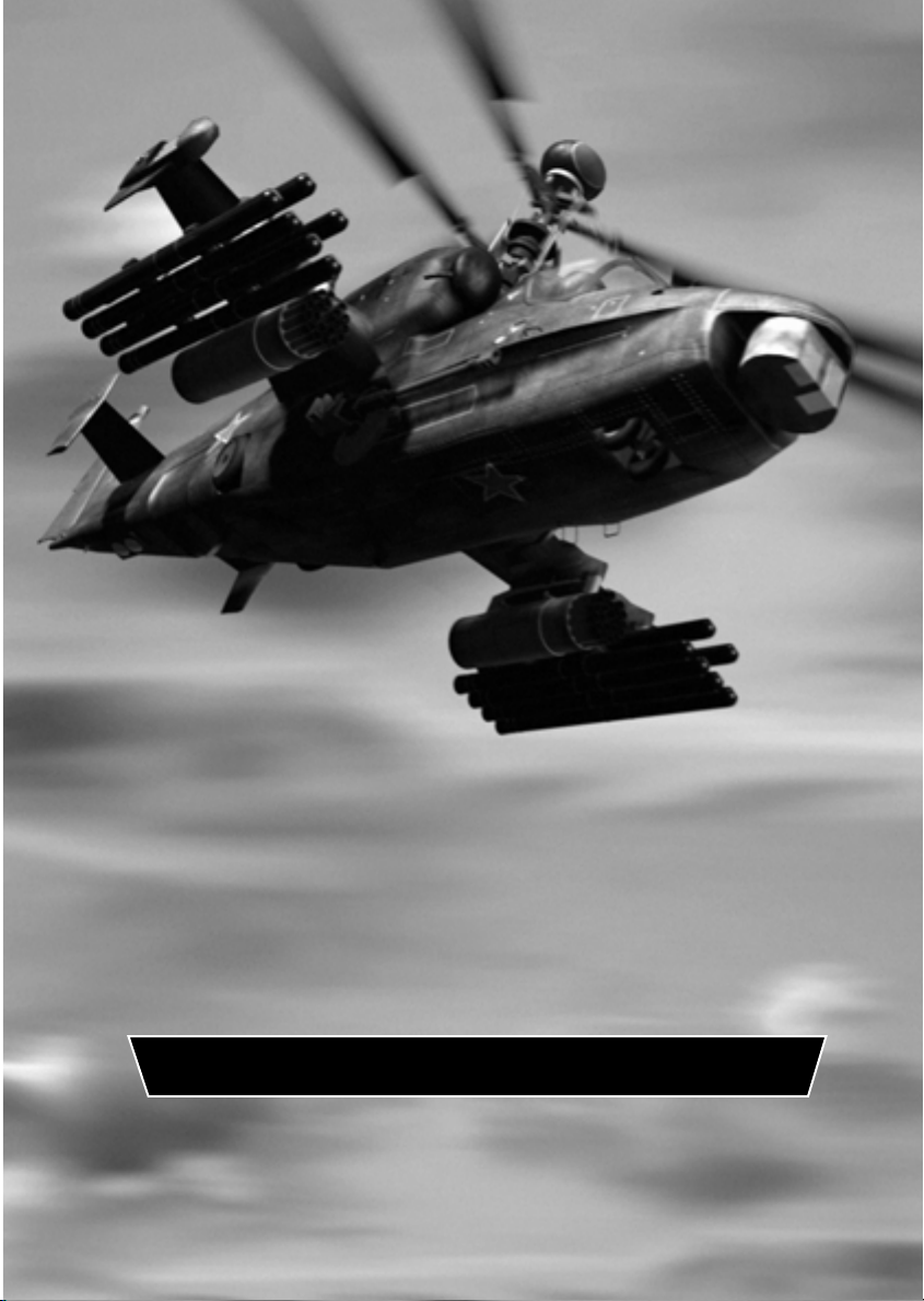
1. INTRODUCTION
Page 8

INTRODUCTION
1.1
Enemy Engaged
RAH-66 Comanche Versus Ka-52 Hokum
Throughout this manual the game title is abbreviated to ‘Comanche Hokum’.
Comanche Hokum is a combat flight simulator showcasing two state-of-the-art helicopters;
the American RAH-66 Comanche and the Russian Ka-52 Hokum B.
Both of these formidable gunships are capable of day, night and all weather missions and
able to operate away from base for extended periods at the front line.
Comanche Hokum provides an accurate simulation of both helicopters including realistic
flight dynamics, authentic weapons systems and detailed cockpits, displays and
instruments. You can fly as both pilot and co-pilot/gunner and the crew are fully animated
to increase the immersion.
There are options to configure the game for both novice and accomplished players. A ‘Quick
Start’ keyboard guide has also been included.
Comanche Hokum features three diverse, real world combat zones, accurately modelled
from digital data. The landscapes have rugged terrain ideally suited to low-level helicopter
combat and making ‘line of sight’ tactics a real part of the game play. Each campaign can
be played from either standpoint and in multiplayer games you can fly co-operatively or
competitively with other players.
The campaign ‘engine’ is fully dynamic and reactive. There are no scripted events or
outcomes. The war rages continuously, even when you are at a base re-arming and refuelling. You fly realistic missions with your wingmen and can co-ordinate attacks via radio
messages. Your skill and judgement will determine success or failure.
Comanche Hokum features in excess of 60 different aircraft and vehicles all of which are
highly detailed and articulated and have realistic payloads and physics.
If you have Apache Havoc installed then Comanche Hokum will allow you to play the Apache
Havoc campaigns and to fly the Apache and Havoc gunships.
Getting Started
Installation
Insert your Comanche Hokum CD into your drive. If ‘Autorun’ is enabled on your system, the
Setup program will start automatically. If Autorun is not enabled, from Windows Explorer,
click on the autorun.exe icon on the Comanche Hokum CD.
Follow the on-screen instructions. Once all of the files have been copied on to your hard
drive, the installation process will create a shortcut for you.
Please note that a Direct3D compatible graphics accelerator card is required to run
Comanche Hokum.
Page 9

INTRODUCTION
Starting
Comanche Hokum requires the full resources of your computer so terminate all other
running applications before starting.
The program requires the Comanche Hokum CD in your drive at all times during use.
To start the game, click on the Comanche Hokum shortcut created by the installation program.
If you experience any difficulty running Comanche Hokum then refer to the ‘Trouble
Shooting’ section in the Appendices.
Exiting
To exit Comanche Hokum return to the Main screen and click on the ‘EXIT’ button.
Alternatively, press l+X at any time.
Quick Start
To get in the air quickly then follow these steps:-
1. On the Main screen select ‘Combat’
2. On the Combat screen select ‘Free Flight’
3. On the Session screen select a scenario then ‘OK’
4. On the Gunship screen select a gunship then ‘SELECT’
You will be transferred to a base and placed in the cockpit of your gunship. You have infinite
weapons and fuel and are invulnerable to crashes. The enemy will not fire at you. These
options may be changed on the Session screen after selecting the scenario.
Refer to the ‘In-Flight’ chapter ‘Basic Handling’ section for the take-off and flight
procedures. Use the ‘Quick Start’ keyboard guide.
Press h to view the map. Press l+ Q to quit.
1.2
Strategy Guide
On the Comanche Hokum CD is a Strategy Guide containing useful game play tactics and
much more. This is a HTML document and requires a web browser to read it.
Look in the ‘Strategy Guides\Comanche Hokum Guide’ folder.
Updates
Check www.razorworks.com for latest information and updates.
Page 10

INTRODUCTION
1.3
Compatibility With Apache Havoc
If you have Apache Havoc installed then Comanche Hokum will allow you to play the Apache
Havoc campaigns and to fly the Apache and Havoc gunships. Effectively giving Comanche
Hokum 6 combat zones and 4 different gunships to fly.
The installed version of Apache Havoc is not upgraded by Comanche Hokum and cannot
play the new campaigns.
For full compatibility you must upgrade the installed version of Apache Havoc to version
1.1E. The upgrade patches are supplied on the Comanche Hokum CD in the ‘Apache Havoc
Patches v1_1e’ folder. Simply launch the patch.exe within the language folder that matches
your version of Apache Havoc. Then run Apache Havoc once to apply the changes.
Conversion Training From Apache Havoc
If you are familiar with Apache Havoc then Comanche Hokum should be straight forward to
get used to. However, you should at least read chapter 2 ‘Menu Screens’ and chapter 3 ‘InFlight’ in this manual.
The Comanche Hokum keyboard layout is nearly identical to the Apache Havoc keyboard
layout. The ‘select object to view’ keys s to v have been changed. The cockpits are now
fully virtual and there are some key changes. The new keys are documented in the ‘In-Flight’
chapter.
If you fly the Apache or Havoc gunships from within Comanche Hokum, their cockpits are
the same as in Apache Havoc and only the pilot’s seat is modelled.
An incoming laser guided missile warning has been added to the Apache Aircraft
Survivability Equipment (ASE) MFD page and to the Havoc Threat Warning Display (TWD).
The Havoc TWD uses the right most lamp to indicate a laser guided missile warning. This
was previously documented as an early warning radar (EWR) lamp.
The new ‘altitude hold‘ function g+H does not apply to the Apache or Havoc gunships.
The Havoc ‘Toggle HUD size’ key has been changed from g+K to l+ K
Comanche Hokum cannot read the Apache Havoc pilot logs.
Page 11
MENU SCREENS
2. MENU SCREENS
Page 12

MENU SCREENS
2.1
Use the mouse to make selections unless stated otherwise. You can click on ‘live’ text – that
is text which changes colour as you move the mouse over it.
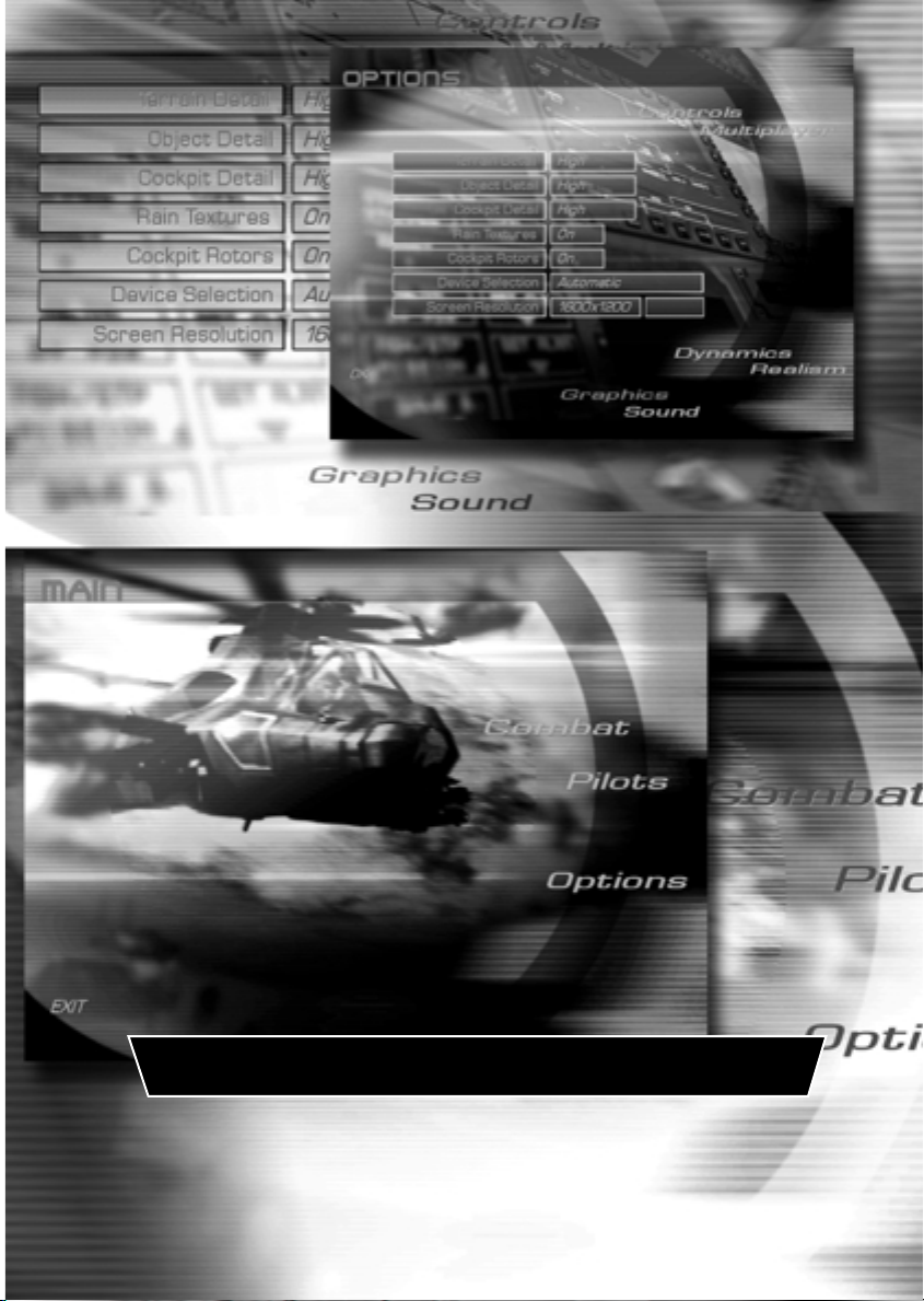
Main Screen
Combat
Choose this option to advance to the Combat screen to select a game type.
Pilots
Choose this option to advance to the Pilots screen where you can select and create pilots
and view their logs and medals.
Options
Select this option to change the game settings.
EXIT
Exit the game.
Pilots Screen
Pilot Roster
The pilot roster allows you to Add, Rename and Delete pilots.
Select a pilot by clicking on his name.
Blue Force
Choose Blue Force to display the selected pilot’s logs and medals for flying the Comanche
(and Apache if Apache Havoc is installed).
Red Force
Choose Red Force to display the selected pilot’s logs and medals for flying the Hokum (and
Havoc if Apache Havoc is installed).
Medals
Choose Medals to view the selected pilot’s medals.
Weapons Log
Choose Weapons Log to view the selected pilot’s weapons log.
Flight Log
Choose Flight Log to view the selected pilot’s log.
Page 13

MENU SCREENS
Rank
The selected pilot’s rank and date commissioned are displayed.
OK
Return to the Main screen.
Options Screen
Controls
Ensure that you have calibrated your game controllers before launching Comanche Hokum
(from the Start menu select Settings then Control Panel then Game Controllers).
Cyclic
Select Keyboard or Joystick for the cyclic stick.
Collective
Select Keyboard or Throttle for the collective lever.
Pedals
Select Keyboard or Rudder Pedals for the pedals.
Device
Cycle through the available game controllers to select the required device.
2.2
Reverse Throttle
A collective lever works in the reverse sense to a jet aircraft throttle. Setting this option to
on makes the collective work in the same sense as the throttle.
Multiplayer
To create (host) or join multiplayer games you will need to select a service provider
(connection method). Some service providers will require additional properties to be
entered.
You can join multiplayer games at any time as long as you have chosen an identical service
provider to the host.
When connecting to another player via a modem connection, the player who answers the
call is automatically assigned the host status. The host must wait in the Multiplayer screen
in order to connect to an incoming call.
Connection
Cycle through the connection options (Internet TCP/IP, Modem, Serial, IPX, etc.) to select
the required service provider and then enter the required parameters.
Page 14

MENU SCREENS
2.3
Dynamics
The options marked with an asterisk (*) are explained fully in chapter 6 ‘Ground School’.
*Blade Stall
Set retreating blade stall effect on or off. The imbalance of lift created by this effect will
cause the helicopter to roll and the pilot to apply constant cyclic corrections. Novice pilots
should turn this effect off.
Cross Couple
Set cross coupling effect on or off. With this option turned on the pilot will notice minimal
turning effect upon large collective inputs. Turning the cross coupling effect off will require
constant yaw input to maintain heading. Novice pilots should turn this effect on.
*Ground Effect
Set ground effect on or off. The ground effect simulates low altitude air cushioning created
by the rotor downwash. Novice pilots should turn this effect off.
Keyboard Assist
Set keyboard assistance on or off. Helicopter flight requires subtle inputs unobtainable from
keyboard control. Keyboard assistance implements a damping factor to help provide these
inputs and allow smoother flight.
Over-Torque
Set over-torque effect on or off. With over-torque set to off you will not get over-torque
warnings when the torque readout exceeds 100% and the gunship will not be damaged.
Novice pilots should turn this effect off.
*Vortex Ring
Set the vortex ring effect on or off. You can unintentionally create a vortex ring around your
main rotor if you make a sustained high-speed descent vertically or at a steep angle. This is
a hazardous situation! Novice pilots should turn this effect off.
Wind
Set wind effects on or off. Novice pilots should turn this effect off.
Realism
Co-Pilot Target ID
Sets the method in which target identifications are reported. Refer to ‘CP/G Assistance:
Target ID’ in the ‘Comanche Cockpit’ and ‘Hokum Cockpit’ chapters.
Co-Pilot ECM
Set Co-Pilot operating counter measures on or off. Set to on and the Co-Pilot will take care
of releasing chaff and flares and will operate the IR and Radar jammers. You can release
extra chaff and flares if required.
Page 15

MENU SCREENS
Avionics
Select either Novice or realistic avionics. With Novice avionics selected you do not need to
operate the targeting devices. Arming a weapon will arm the HIDSS / HUD targeting modes
automatically and you can designate targets simply by looking at them. Refer to the
‘Comanche Cockpit’ and ‘Hokum Cockpit’ chapters.
Also, with Novice selected your wingmen are initially set to ‘Weapons Free’ so you do not
need to send a radio command to make them fire.
Difficulty
The difficulty option affects the enemy's response time and the amount of weapon damage
incurred. This only affects you and not the other entities in the world. In multiplayer games
each player retains their own difficulty level. That is, this value is not set globally by the
server. Therefore a novice player can compete with more experienced players by adjusting
their respective difficulty levels.
At the Easy difficulty setting, the player’s weapons do not take account of ‘armour penetration
angles’. Usually, if a weapon hits the front of a tank, where it is more heavily armoured, then
less damage will be inflicted than if the weapon hits the rear or sides of the tank.
Graphics
Terrain Detail
Select 3D terrain detail to suit your processor speed. High detail demands more processor
power than Low detail.
2.4
Object Detail
Select 3D object detail to suit your processor speed. High detail demands more processor
power than Low detail.
Cockpit Detail
Select cockpit detail to suit your processor speed. High detail demands more processor
power than Low detail.
Rain Textures
Cockpit rain textures may be set on or off as a matter of preference.
Cockpit Rotors
The main rotor blur effect visible from the cockpit may be set on or off as a matter of
preference.
Device Selection
Cycle through the available hardware graphics devices and select the hardware which has
the best Direct3D support. Changing device requires you to restart Comanche Hokum.
Screen Resolution
Cycle through the available screen resolutions and click ‘Accept’ to apply.
Page 16

MENU SCREENS
2.5
Sound
Sound Effects
Set sound effects on or off.
Music
Set music on or off.
Speech
Set all speech on or off.
Co-Pilot Speech
Set Co-Pilot speech on or off.
OK
Exit the Options screen.
Combat Screen
There are three different game types offered in the Combat screen plus a demo mode.
Campaign
Campaign games are large-scale dynamic campaigns based over the entire map. To win the
campaign you need to complete all of the given objectives.
Skirmish
Skirmish games are mini-campaigns contained within a small area of the map. Skirmish
games provide useful practice before taking on a full campaign and also require much less
bandwidth in multiplayer games.
Free Flight
Free Flight games allow you to explore all of the flying areas, practice flying and familiarise
yourself with the avionics and weapons systems.
Demo
The demo allows you to watch a campaign in action.
Press l+ Q or c to quit the demo.
CANCEL
Return to the Main screen.
Page 17

MENU SCREENS
Session Screen
The session list shows all of the available games.
New games are listed in white text. If you have selected a multiplayer connection then
starting a new game makes you the host of that game.
Existing multiplayer games are listed in amber text. You may join these games at any time.
Saved games are listed in green text. Saved games may be renamed or deleted.
After you have selected a game, the game details and options are displayed.
Select ‘OK’ when you are ready to continue.
Select ‘CANCEL’ to return to the Combat screen.
Gunship Screen
From the Gunship screen select which side you want to play the campaign from.
Select ‘RAH-66 Comanche’ for the Blue Force and ‘KA-52 Hokum B’ for the Red Force.
If you have Apache Havoc installed then you can choose between flying Comanches and
Apaches or Hokums and Havocs in the campaign.
Select ‘SELECT’ to continue to the Campaign and Mission Planning screen.
Select ‘CANCEL’ to return to the Session screen.
2.6
Page 18
MENU SCREENS
2.7
Campaign and Mission Planning Screen
The Campaign and Mission Planning screen is the focal point of the campaign. From here
you get an overview of the campaign and can assess the current situation in order to decide
your next mission.
General Layout
SELECT INFORMATION
SELECT
MISSION
AND
GUNSHIP
INFORMATION WINDOW
CAMPAIGN
TIME
CURRENT MISSION STATUS
EXIT
CURRENT GUNSHIP STATUS
CLEAR/QUIT MISSION
Diagram 2.1: General layout of the Campaign and Mission Planning screen
MESSAGE WINDOW
CONFIRM/
COCKPIT
Familiarise yourself with the layout of this screen – try selecting all the options. You will
notice that many items react to a ‘mouse over’ event by displaying additional relevant
information as you move the mouse pointer over them. The additional information may
be displayed in the message window, on the map or in the current mission and gunship
status lines.
Generally you can click on graphical icons and ‘live’ text – that is text that changes colour
as you move the mouse pointer over it.
Page 19

MENU SCREENS
Selecting a Mission and Gunship
There are several ways of selecting a mission and gunship and you can select them in any
order.
For instance, you may prefer to select a mission first simply because you want to fly a
particular type of mission. Alternatively you may opt to select a gunship first so that you
can fly with other players in a multiplayer game or you want to fly a particular type of
gunship if you have Apache Havoc installed.
‘Auto-Select’
The easiest way to select a mission and gunship is to use the auto-select function:-
1. Click the ‘Auto-Select’ text in the current mission status line and a mission will be
automatically selected. The mission briefing is displayed in the information window.
2. Click the ‘Auto-Select’ text in the current gunship status line and a gunship will be
automatically selected for the mission. The flight group details are displayed in the
information window.
3. Click ‘Confirm’ then ‘Cockpit’ to fly the mission.
‘Available’ and ‘OOB’ (Order Of Battle)
Select the ‘Available’ button to list all of the missions or groups available to you.
Select the ‘OOB’ button to list the ‘Order Of Battle’ for all of your forces (air, land and sea).
You can view missions, groups and bases.
2.8
‘Unassigned’ Missions
Unassigned mission are missions which have not been assigned to a flight group yet. If you
select an unassigned mission you then need to select a flight group in order to fly the
mission.
Unassigned missions may be taken by computer-controlled (AI) flight groups or by other
players in multiplayer games. Unassigned missions will eventually expire (timeout) if they are
not taken.
To select an unassigned mission and a gunship:-
1. Click ‘Clear’ / ’Quit Mission’ to clear any previously selected missions or gunships.
2. Select ‘Available’ and ‘Missions’.
3. Unassigned and assigned missions are listed, for example:-
Unassigned
[3 x RECON]
[2 x CAS]
Assigned
[1 x SEAD]
Page 20

MENU SCREENS
2.9
4. Click on a mission type to display the missions available, for example:-
Unassigned
[3 x RECON]
RECON #1
RECON #2
RECON #3
[2 x CAS]
Assigned
[1 x SEAD]
5. As you move the mouse pointer over the missions, details of the mission are shown in
the message window and the current mission status line. The mission is indicated on
the map (if it is view).
6. Click on a mission and a full briefing for the mission is displayed in the information
window.
7. Click ‘Accept’ to accept the mission. The ‘Groups’ button is automatically selected and
the flight groups available for this mission are listed. If no flight groups are available
then click ‘Clear Mission’ to start again.
8. Click on a flight group type to expand the groups available, for example:-
[2 x Recon / Attack Helicopters]
Freelancer
Gator
[1 x Attack Helicopters]
9. As you move the mouse pointer over the flight groups, details of the group are shown
in the message window and the current gunship status line. The flight group is indicated
on the map (if it is in view).
10. Click on a flight group and the group’s details are displayed in the information window.
11. You are normally assigned the flight group leaders gunship (i.e. ‘1-1 RAH-66 Comanche’)
but you can select another from the list.
12. Click ‘Accept’ to accept the gunship.
13. Click ‘Confirm’ then ‘Cockpit’ to fly the mission.
‘Assigned’ Missions
If you have accepted an assigned mission then the flight group is already selected but you
can change gunship within the group. Click ‘Accept’ to the gunship. Click ‘Confirm’ then
‘Cockpit’ to fly the mission.
Page 21

MENU SCREENS
‘Completed’ Missions
Completed missions are only listed when the ‘OOB’ option is selected.
Map
There are many maps displayed in various contexts, however, the functionality of all maps
is the same.
Mouse Controls
The map reacts to ‘mouse over’ events. Simply point at icons to find out what they are.
Point to a location on the map and right-click to centre the map around this position.
Point to a location on the map and left-click to ‘goto’ (that is move your gunship to) this
position. This option is only available in Free Flight games.
Keyboard Controls
[]\^Move map
= Zoom in
- Zoom out
+ (numpad) Zoom in
- (numpad) Zoom out
> Zoom in
< Zoom out
l+= Increase time acceleration (single player)
l+ - Decrease time acceleration (single player)
l+ + (numpad) Increase time acceleration (single player)
l+ - (numpad) Decrease time acceleration (single player)
` Centre map on player
C Centre map on player
h Toggle cockpit/menus
2.10
Map Buttons
Maximise
Maximise map.
Minimise
Minimise map.
Page 22
2.11
MENU SCREENS
Zoom In
Zoom in.
Zoom Out
Zoom out.
Side
Toggle ‘side’ map.
The side map indicates the territorial possession of both sides.
Fog
Toggle ‘fog’ map.
The fog map indicates areas in which you have little or no intelligence.
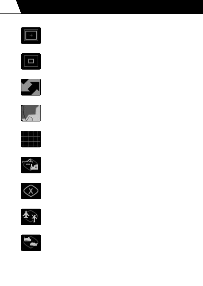
Grid
Toggle the map grid.
Keysites
Toggle keysite icons. Keysites are tactical sites such as airbases,
FARPs, ports, oil refineries, etc.
Missions
Toggle mission destinations.
Air Forces
Toggle air force icons.
Ground Forces
Toggle ground force icons.
Page 23
MENU SCREENS
Sea Forces
Toggle sea force icons.
Air Defences
Toggle air defence icons.
Ground Radar (threat circles)
Toggle air defence radar threat circles.
Track
Depending on the map context the track button does the following:-
1. Group information displayed – track the selected unit.
2. Mission information displayed – does nothing.
3. Base information displayed – does nothing.
4. All other maps – track the player’s gunship.
2.12
Goto
Toggle ‘goto’ feature. Only available in Free Flight games.
Map Icons
Move the mouse pointer over any map icon and details will be displayed in the message
window.
Event
The most recent event log message is displayed in the message window
and the event locator is displayed on the map to show the origin of the
message. Click on the message window to display the event log in the
information window.
Page 24

2.13
MENU SCREENS
Explosions
Explosions are drawn on the map indicating current engagements.
Waypoints
The waypoint route is displayed on the map.
Editing Waypoint Routes
The waypoint route can only be edited once the mission and gunship have been
confirmed (by clicking ‘Confirm’).
To move a waypoint, select it with the mouse pointer and drag it to a new location. The
start base, landing base and objective waypoints cannot be moved.
To insert a waypoint, click on the ‘+’ symbol between the two waypoints that you wish to
insert a new waypoint.
To delete a waypoint, highlight the waypoint by moving the mouse pointer over the
waypoint and press the ;key. The start base, landing base and objective waypoints
cannot be deleted.
Mission Briefing and Debriefing
The mission briefing is displayed in the information window. The details of the mission are
listed and a short account of the mission objectives is given.
After a mission is completed (successfully or unsuccessfully) the mission debriefing is
displayed in the information window.
To display your briefing or debriefing click the mission name (i.e. ‘RECON #2’) in the
current mission status line.
The mission briefing is available as soon as the mission is complete and not when you have
returned to base. At this point you can quit the mission (an AI pilot will fly the gunship back
to base) and you can select another mission to fly.
Promotion and Medals
After a mission you may be promoted or be awarded a medal. Details are given in the
debriefing.
Sit Rep (Situation Report)
The Sit Rep outlines your campaign objectives and gives an indication of the campaign
progress using ‘force strength’ and ‘kills/losses’ indicators.
In order to win the campaign your forces must successfully complete all of the campaign
objectives.
Page 25

MENU SCREENS
Some objectives require your forces to capture an enemy installation. To achieve this your
forces must weaken the installation via strike missions. Once battle damage assessment has
shown the installation to be sufficiently weakened your forces will attempt to insert troops
to capture it.
Log (Event Log)
The event log keeps account of all the significant actions that have occurred during the
campaign.
The event log is listed with the latest event at the top. Click on any event text to view the
location of the message origin.
Payloads
After selecting a gunship you can change the weapon loadout. You can only change the
gunship’s weapons when you are landed at an airbase, carrier or FARP.
To change weapons cycle through the weapons available for each pylon or select a default
weapon loadout (air-to-ground, air-to-air or recon/scout).
You may change the weapon loadout for any of the gunships in your flight group. For
gunships other than Apache Longbows, Comanches, Havocs and Hokums you can only
select the three default options.
Chat
Use the chat facility to communicate with other players in multiplayer games.
2.14
Options
You can change the game options during a campaign, however, some options will be
unavailable and are greyed out.
Save
Save a campaign at any time. The saved game will be available on the Session screen.
Enter a filename for the saved game (restricted to 8 characters – there is no need to enter
a file extension).
Quit Campaign
To quit the campaign click the ‘Exit’ button or press l+ Q.
Page 26
BASICS
3. IN-FLIGHT
Page 27

IN-FLIGHT
3.1
Basic Handling
If you are a novice pilot then it is recommended that you read the ‘Ground School’ section
of the manual to familiarise yourself with the basic principles and handling of a helicopter.
This section will guide you through the flight controls as required for Comanche Hokum
and explain the function of the automatic flight systems; ‘autopilot’, ‘altitude hold’ and
‘hover hold’.
Select a ‘Free Flight’ mission to practice your flight procedures. Ensure that you select a
passive environment and turn the collisions and weapon damage off.
The flight controls are the same for both Comanche and Hokum.
To re-iterate the lesson from Ground School:-
"It is worth emphasising that all your control movements ('control
inputs') should be as smooth and deliberate as possible. Sudden,
violent control inputs are to be avoided whenever possible, but
especially in hovering or low-speed flight. Make sure that you know
where to find airspeed, altitude and vertical velocity readouts on
the Head-Up Display (HUD)."
Taking off and rising to the hover
1. Release the rotor brake R
2. The rotor blades will start to spin and the canopy doors will close
3. When the main rotor RPM has reached 90% the ‘RTR RPM’ warning light will turn off
and the helicopter is ready for take-off
4. Release the wheel brakes B
5. Watching the torque value on the head-up display, gently increase the collective to 65-
75% Q
6. The helicopter will start to climb
7. Climb to an altitude of 100 feet / 30 metres so that the helicopter is out of
‘ground effect’
8. Adjust the collective to hold the helicopter in a steady hover Q and A
Transition from the hover to forward flight
1. Ease the cyclic forward and the helicopter will start to accelerate \
2. The helicopter will lose altitude so gently increase the collective to compensate for
this Q
Page 28

IN-FLIGHT
Climbing and diving
1. Pull back on the cyclic to climb ^
2. The helicopter will climb but lose forward speed
3. Push the cyclic forward to regain forward speed \
4. Raise the collective to climb Q
5. The helicopter will climb but gain forward speed
6. To climb without losing or gaining speed you need to simultaneously pull back on the
cyclic and raise the collective ^ and Q
7. Push the cyclic forward to dive \
8. The helicopter will lose height but gain forward speed
9. Pull the cyclic back to reduce the dive ^
10. Lower the collective to lose height A
11. The helicopter will lose height and forward speed
12. To dive without losing or gaining speed you need to simultaneously push forward on
the cyclic and lower the collective \ and A
3.2
Turning in forward flight
1. When the helicopter is hovering or flying at low speed (below 60 knots / 110 km/h) use
the pedals to turn Z and X
2. At higher speeds, turning is accomplished by tilting the cyclic left or right to bank the
helicopter ] and [
3. If you fly sustained or steeply-banked turns you’ll need to raise the collective Q or ease
back on the cyclic ^ (with loss of some forward speed) to avoid losing height
Slowing to the hover from forward flight
1. Start the manoeuvre by pulling back on the cyclic ^ to tilt the helicopter backwards
2. Lower the collective to prevent the helicopter from climbing A
3. As the helicopter slows, gently raise the collective Q to compensate for the diminished
main rotor thrust
4. As you approach the hover ease the cyclic forward \ to bring the helicopter level,
simultaneously raising the collective Q to maintain altitude
5. Use the pedals Z and X as necessary to keep the helicopter straight
Page 29

IN-FLIGHT
3.3
Landing
1. From a steady hover, gently lower the collective A and the helicopter will begin to lose
altitude
2. Watching your vertical speed, adjust the collective Q and A to maintain a steady rate
of descent
3. Just before touchdown reduce the rate of descent to soften the landing
4. After touchdown, bottom the collective A
5. Engage the wheel brakes B
6. Engage the rotor brake R
7. The rotor blades will spin down and the canopy doors will open
Taxiing
1. With the rotor blades spun up and the wheel brakes disengaged, increase the collective
Q to between 25 and 50%
2. To start taxiing, push gently forward on the cyclic \
3. Use the pedals Z and X to steer the helicopter
4. To slow down, ease back on the cyclic ^
5. To stop apply the wheel brakes B
Trim
Trim re-centres the cyclic to the currently held position. Trim is useful when flying long
distances in a straight line so that you do not need to keep pressure on the cyclic.
Autopilot
The autopilot system will fly the helicopter around the waypoint route and eventually land
back at base. Autopilot will not engage the enemy at ‘target’ waypoints.
G Autopilot (engage/disengage)
Autopilot is unavailable if the helicopter control systems are damaged or if the helicopter is
out of fuel.
Autopilot cannot be engaged when the helicopter's radar altitude is below 25 metres
(approximately 80 ft).
Coming in to land at a base, the helicopter may enter a holding pattern until a landing pad
becomes available.
Page 30

IN-FLIGHT
Altitude Hold
The altitude hold system will attempt to hold the helicopter at the current radar altitude, in
effect, terrain following for nap of the earth flying.
Altitude hold is unavailable if the helicopter control systems are damaged or if the
helicopter is out of fuel.
The radar altitude setting can be increased or decreased by one unit at a time (1 foot
Comanche, 1 metre Hokum).
g+ H Altitude hold (engage/disengage)
g+ J Decrease altitude hold level
g+ K Increase altitude hold level
Hover Hold
The hover hold system will attempt to hold the helicopter in a stationary position
(station keeping).
Hover hold is unavailable if the helicopter control systems are damaged or if the helicopter
is out of fuel.
Hover hold can only be engaged if the horizontal velocity of the helicopter is below 20 knots
(approximately 40 Km/h).
Use collective to adjust the hover height and yaw to adjust the heading. Hover hold will
disengage with any cyclic input.
Hover hold bleeds off any horizontal velocity and adjusts the collective to zero the vertical
velocity. It is not an immediate effect and may take a few moments to stabilise. If you are
using a throttle stick then you will have to adjust the collective manually.
Stable hover hold is the same as hover hold except that it maintains altitude automatically
for players with throttle sticks.
H Hover hold (engage/disengage)
m+ H Stable hover hold (engage/disengage)
3.4
Page 31

IN-FLIGHT
3.5
Missions
Mission Types
The following airborne mission types are contained within Comanche Hokum.
Only missions marked with an asterisk (*) can be flown by the player. You will receive
confirmation of a successful mission completion or failure.
*Anti-ship Strike
Anti-ship strike missions are direct airborne assaults against enemy surface ships.
The mission is successfully completed when sufficient enemy ships have been destroyed.
BARCAP (BARCAP)
BARCAP missions are used to defend surface ships from attack. Fighter aircraft fly a circuit
(barrier) between the sea force and any potential threat.
*BDA (Battle Damage Assessment)
BDA missions are flown following a strike mission to assess the damage caused. Depending
on the information gained subsequent strike or troop insertion missions may be generated.
For successful mission completion the flight group leader must fly to within 500m of the
target waypoint and transmit recon data using the ‘Transmit Recon’ radio message.
*BAI (Battlefield Air Interdiction)
BAI missions are used to strike rear area reinforcements and supplies in order to destroy or
delay the enemy’s military potential before it can be used against friendly forces.
The mission is successfully completed when sufficient ground forces have been destroyed.
*CAP (Combat Air Patrol)
CAP missions are airborne patrols over a friendly area for the purpose of intercepting and
destroying enemy aircraft before they reach their target.
CAP missions last for a predetermined period of time. The mission is successfully
completed when this time has elapsed.
Page 32

IN-FLIGHT
*CAS (Close Air Support)
CAS missions are airborne attacks against enemy forces which are in close proximity to
friendly forces.
The mission is successfully completed when sufficient enemy ground forces have been
destroyed.
*Escort
Armed escort missions provide protection for any vulnerable aircraft flying in a hostile area.
The mission is successfully completed when the escorted aircraft reach their destination.
*Ground Strike
Ground strike missions are direct airborne assaults against enemy ground installations.
The mission is successfully completed when sufficient enemy ground structures have been
destroyed.
3.6
OCA Strike (Offensive Counter Air Strike)
OCA strike missions are airborne attacks against landed air units at enemy airbases or
FARPs.
OCA Sweep (Offensive Counter Air Sweep)
OCA sweep missions are airborne attacks against enemy aircraft patrolling a target area.
*Recon (Reconnaissance)
A recon is mission is undertaken to obtain information about the activities and resources of
the enemy.
For successful mission completion the flight group leader must fly to within 500m of the
target waypoint and transmit recon data using the ‘Transmit Recon’ radio message.
Repair
Repair missions are used to deploy engineers and equipment at friendly ground installations
in order to repair damage caused by the enemy.
Page 33

IN-FLIGHT
3.7
*SEAD Strike (Suppression of Enemy Air Defences)
SEAD missions are used to destroy enemy air defences.
The mission is successfully completed when sufficient enemy air defence units have been
destroyed.
Supply
Supply missions are undertaken to deliver supplies to units and installations.
*Transfer
Transfer missions are used to move aircraft to where they are most needed.
The mission is successfully completed when the aircraft reach their destination.
Troop Insertion
Troop insertion missions are used to capture an enemy installation once the area has been
secured by a previous Strike or SEAD mission.
Page 34

IN-FLIGHT
Radio Messages
You can send radio messages to your flight group, individual wingmen or the local base.
Radio messages marked with an asterisk (*) can only be transmitted by the flight group
leader.
@ Display radio message menu
0 to 9 Select menu option
c Exit menu (at any time)
l+@ Repeat radio message (the last message received)
m+A Attack my target
Any on-screen radio messages displayed in grey text are not available for some reason (i.e. you
need to be the flight group leader, the radio message applies to a certain mission type, etc.).
Flight Group and Wingman Commands
Attack My Target
Instructs the selected wingman (or the entire flight group) to attack your current target.
Your order will only be carried out if your target is not a friendly target and your
wingmen are capable of attacking it. This order cancels ‘Weapons Hold’.
If this instruction is sent to a human-controlled wingman, he will receive a text message
at the top of the screen showing the sender’s name and the target’s name, heading and
range. The heading and range are calculated from the recipient’s position.
3.8
Help Me
Instructs the selected wingman (or the entire flight group) to attack your current
pursuers. This order cancels ‘Weapons Hold’.
*Return To Base (flight group only)
Aborts all current missions. The whole flight group will return to base.
*Weapons Hold
Any flight group members in ‘Weapons Hold’ state will not fire at anything. ‘Weapons
Hold’ is cancelled by the orders ‘Weapons Free’, ‘Attack My Target’ and also if the flight
group member is fired at.
*Weapons Free
Cancels ‘Weapons Hold’ for the selected wingman or the entire flight group.
Page 35

IN-FLIGHT
3.9
*Hold Position
Using the ‘Hold Position’ command, wingmen can be instructed to remain in their
current position hovering at low altitude. The following conditions apply:-
1.This command cannot be issued to wingmen who are landing or landed.
2. If the wingman is taking off when the ‘Hold Position’ command is issued then he will
remember the position he was at when the command was given and return to wait at
that position once he has completed taking off.
3. If the wingman picks up a target, or is given a target by either ‘Attack My Target’ or ‘Help
Me’ commands, and is in ‘Weapons Free’ state, then he will continue attacking his targets
and return to his ordered hold position once all his targets are destroyed or a ‘Weapons
Hold’ command is issued.
The ‘Hold Position’ command will be cancelled by any of the following events:-
1. A ‘Rejoin Formation’ command is issued.
2. The flight leader reaches his final waypoint.
3. The flight leader is killed.
4. The player releases control of the flight leader (i.e. quits).
*Rejoin Formation
Cancels a ‘Hold Position’ command and allows the wingman to proceed as normal.
*Bob-Up
Used to co-ordinate ground attacks. If your wingman is in ‘Weapons Hold’ state, then
he will remain masked at his cover position until you give the order to ‘bob-up’. Upon
receiving this command he will increase altitude until he has sufficient line of sight to
the target, fire, and then re-mask. A wingman in ‘Weapons Free’ state will bob-up and
fire automatically. This option is only available to wingmen who are masked at their
cover positions and waiting for your command.
Page 36

IN-FLIGHT
*Formation List (flight group only)
Select the new flight formation and the wingmen will re-position themselves.
Row Left Row Right
3.10
1-4 1-3 1-2 1-1
1-1 1-2 1-3 1-4
Echelon Left Echelon Right
1-1
1-2
1 1-3
1-4
1-1
1-2
1-3
1-4
Column Wedge
1-1
1-2
1-1
1-3
1-4
1-4
Diagram 3.1: Flight group formations (‘1-1’ is the flight group leader)
1-3 1-2
Page 37

3.11
IN-FLIGHT
Request Target List (other players only)
Only available if the selected wingman is human-controlled. The contents of the
selected wingman’s target list are added to your own target list.
Keyboard Message (other players only)
Only available if the selected wingman is human-controlled. Type in your own message
using the keyboard, press h when finished to send it, or press c at any time to
cancel.
LOCAL BASE
Request Airstrike
Creates a strike task depending on what you are targeting:-
1. Targeting an enemy structure will create a ground strike mission.
2. Targeting an enemy SAM or AAA will create a SEAD mission.
3. Targeting an enemy frontline ground unit will create a Close Air Support mission.
Request Artillery
Requests an artillery strike against the area surrounding your current target. The request
will be carried out if the target is valid and there is a friendly artillery unit within range.
Request Assistance
Scans the area for any friendly airborne units and instructs them to intercept your
current pursuers.
Transmit Recon
Only available when your current waypoint requires transmission of reconnaissance
data. If you are within 500m of your recon target then select this option to complete
the mission.
Page 38

IN-FLIGHT
Views
Cockpit Views
In Comanche Hokum both pilot and co-pilot cockpits are included and you may assume
either crew role by switching seats. The cockpits are ‘virtual’ and may be panned as though
you are rotating the pilot’s head. There are also some close-up views of the displays.
The crew themselves are fully animated to increase the immersion of the game. There is a
special ‘Crew camera’ to observe them with.
c Switch pilot/co-pilot seat
g+ []\^ Pan view
o Forward view
p Instrument view
q Left MFD view, press again for instrument view
r Right MFD view, press again for instrument view
m+ p Hokum HUD view, press again for forward view
Alternative keys:-
m+ \ Pilot’s seat
m+ ^ Co-pilot’s seat
m+ ] Left MFD view, press again for instrument view
m+ [ Right MFD view, press again for instrument view
l+ \ Forward view
l+ ^ Instrument view
l+ ] Look left
l+ [ Look right
Cockpit Graphics
The cockpit graphics detail is selected using the Options Screen ‘Graphics’ menu. The
cockpit detail can also be changed in-flight:-
l+ r Increase cockpit detail
l+ q Decrease cockpit detail
You can fly without cockpit graphics but this leaves you with no points of reference and
it is easy to get disorientated. Alternatively there is a ‘glass’ cockpit option:-
l+ o Toggle cockpit graphics
l+ p Toggle glass cockpit
The blurred main rotor blades visible from the cockpit can be switched off in the
Options Screen 'Graphics' menu. The blurred main rotors can also be toggled in-flight:-
g+ R Toggle blurred main rotor blades
3.12
Page 39

3.13
IN-FLIGHT
Padlock Views
Padlock views automatically rotate the pilot’s (or co-pilot’s) head in order to track various
items:-
1 Padlock target
2 Padlock wingman
3 Padlock air threat
4 Padlock ground threat
5 Padlock incoming missile
6 Padlock waypoint
0 Unpadlock
Padlock Target
Padlocks the current target.
Padlock Wingman
Wingmen are other helicopters in your flight group. The wingmen are padlocked in
group order (i.e. ‘Phantom 1-1’ then ‘Phantom 1-2’ and so on). Press 2 again to cycle
through the wingmen.
Padlock Air Threat
Air threats are any aircraft which are targeting your gunship. The nearest air threat is
padlocked first. Press 3 again to padlock other air threats.
Padlock Ground Threat
Ground threats are any ground vehicles which are targeting your gunship. The nearest
ground threat is padlocked first. Press 4 again to padlock other ground threats.
Padlock Incoming Missile
The nearest missile is padlocked first. The nearest missile is defined in terms of ‘time
to impact’ as opposed to actual distance. Press 5 again to padlock other incoming
missiles.
Padlock Waypoint
Padlocks the current waypoint.
Unpadlock
Unpadlock cancels any padlock view.
Page 40

IN-FLIGHT
External Views
Selecting external views is split into two operations; selecting the object to view and
selecting the camera to view with. There is no given order in which these operations have
to occur.
Player’s Shortcuts
To quickly locate objects associated with the player:-
s Player’s gunship
t Player’s target
u Player’s weapon
v Player’s padlock
Player’s Gunship
Select the player’s gunship. External views of the player’s gunship show the head-up
display (HUD). This can be toggled on or off by pressing g+p
Player’s Target
Select the player’s target.
Player’s Weapon
Select the player’s weapon. Only viewable weapons can be selected – i.e. not cannon
shells – and if no weapon has been fired then the Weapon camera will be primed for
when a weapon is fired.
3.14
Player’s Padlock
Select the player’s padlock. This does not apply to waypoints.
Select Object To View
In Comanche Hokum there are many objects (aircraft, ground vehicles and ships)
involved in each campaign. In order to quickly locate any specific object use the ‘Select
Object To View’ menu simply referred to as the ‘Object’ menu.
z Toggle Object menu
View
Select the main group of objects to view:-
+s View all
g
+t View wingmen
g
g
+u View players
g+v View available gunships
Page 41

3.15
IN-FLIGHT
View All
View all objects. Resets all Object menu options to ‘All’.
View Wingmen
View wingmen only.
View Players
View other player’s gunships only (in multiplayer games).
View Available Gunships
View available gunships only. In Comanche Hokum it is possible to change gunship inflight. Press g+ v to view available gunships only. Press l+ v to cycle the
available gunships. Press U to fly the gunship.
Range
View objects within a given range of the player’s gunship. If the player has not selected
a gunship then this option will be set to ‘All’.
g+ = Increase view range
g+ - Decrease view range
Alternatively (for Japanese keyboards):-
g+ +(Numpad) Increase view range
g+ -(Numpad) Decrease view range
Side
Select ‘side’ of objects to view.
l+ s next side
l+ s previous side
Category
Select ‘category’ of objects to view.
m+ u next category
m+ t previous category
Ty p e
Select ‘type’ of objects within a category to view.
l+ u next type
l+ t previous type
Page 42

IN-FLIGHT
Object
Select object to view. The number of objects available is shown in parenthesis.
l+ v next object
m+ v previous object
Short Object Menu
There is a shortened form of the Object menu displayed on the third line of the
‘External View Text’ (see below). This shows the current Object menu settings. When
you become accustomed to selecting an object to view you will probably no longer
require the full Object menu.
Select Camera
Any camera can be selected for any object:-
w Chase camera (pan and zoom)
m+ w Reset chase camera position behind object
g+ w Toggle lock/unlock chase camera to object
x Fly-by camera
m+ x Drop camera
l+ x Static camera (pan)
g+ x Weapon camera (only viewable weapons can be selected – i.e. not cannon
shells – and if no weapon has been fired then the Weapon camera will be primed for
when a weapon is fired)
y Auto-action camera (seeks out action within the limits of the Object menu settings
and uses a mix of cameras)
m+ y Cinematic camera (cinematic camera moves)
l+ y Crew camera (press again to cycle the camera positions for the selected crew
member)
g+ []^\ Pan view
g+ < Zoom out
g+ > Zoom in
3.16
External View Text
The external view text displayed at the bottom of the screen may be toggled on or off
by pressing l+ z.
Inset Target
If an object is tracking a target then an ‘inset’ view of the target can be displayed in the
top right corner of the screen.
g+ z Toggle inset target
Page 43

3.17
IN-FLIGHT
High Resolution Support
The screen resolution for Comanche Hokum is selected using the Options Screen ‘Graphics’
menu. The screen resolution can also be changed in-flight:-
m+ r Increase screen resolution
m+ q decrease screen resolution
m+ o set screen resolution to 640x480
The screen resolution can be set to any supported ‘square aspect ratio’ setting between
640x480 and 1600x1200. Square aspect ratio simply means that the pixels are square.
When you change the screen resolution the new setting appears momentarily in the top
centre of the screen (width x height).
If increasing the screen resolution leaves you looking at a blank screen it is likely that the
screen resolution has exceeded the refresh rate of your monitor. If this happens you should
decrease the screen resolution.
Some 3D cards are able to switch to higher screen resolutions but may exhibit some texture
mapping problems. If this happens you should decrease the screen resolution.
If the program crashes whilst attempting to switch to an unsupported screen resolution
then re-run the program using the /3dreset command line option to set the screen
resolution to 640x480. Refer to ‘Trouble Shooting’.
The screen resolution that you select becomes the default setting for subsequent games or
until you change it again.
Note that changing the screen resolution may take a few seconds and may cause the screen
to glitch.
Screen Shots
To take a screen shot in-flight press d. This will write a TGA file to the
COHOKUM\SCRNSHOT\LARGE folder. Up to 1000 screen shots may be taken before the
folder requires clearing.
Page 44

IN-FLIGHT
Controls
Standard Joystick Configuration
Stick Cyclic
Hat switch (POV) Pan view
Button 1 Fire weapon
Button 2 Select weapon
Button 3 Select target
Button 4 Padlock/unpadlock target
Programmable Joystick Configurations
Programmable joystick configuration files are located in the 'Joystick' folder on the
Comanche Hokum CD.
‘Sticky’ Keys
Occasionally you may experience problems with 'sticky' keys.
For example, the torque value may continue to rise or fall even though you have released
the collective keys. Pressing and releasing the appropriate key will solve the problem
(press Q if the torque value is continuously rising, or press A if the torque value is
continuously falling).
3.18
Game
l+ X Exit game
l+ Q Quit mission/campaign
P Pause (single player)
l+ = Increase time acceleration (single player)
l+ - Decrease time acceleration (single player)
Alternatively (for Japanese keyboards):-
l+ +(Numpad) Increase time acceleration (single player)
l+ -(Numpad) Decrease time acceleration (single player)
h Toggle cockpits/menus
l+ I Toggle in-flight intelligence messages
l+ R Rearm, refuel and repair (cheat)
d Take screenshot
Page 45

3.19
IN-FLIGHT
Flight Controls
Cyclic, Collective, Tail Rotor
] Cyclic left
[ Cyclic right
\ Cyclic up
^ Cyclic down
Q or = Increase collective
A or - Decrease collective
Z Tail rotor left
X Tail rotor right
T Trim cyclic
m+ T Clear trim
Autopilot
G Autopilot (engage/disengage)
g+ H Altitude hold (engage/disengage)
g+ J Decrease altitude hold level
g+ K Increase altitude hold level
H Hover hold (engage/disengage)
m+ H Stable hover hold (engage/disengage)
Miscellaneous
R Rotor brake (engage/disengage)
B Wheel brake (engage/disengage)
l+ G Gear (raise/lower)
g+ E Eject (Hokum)
Cockpit
Warnings
M Acknowledge master caution
l+ F Fire extinguishers (once per mission)
Page 46

Radio Messages
@ Display radio message
l+ @ Repeat radio message
m+ A Attack my target
Navigation
W Select next waypoint (flight group leader)
m+ W Select previous waypoint (flight group leader)
Night Flying
N Night vision (on/off) – PNVS (Comanche) / NVG (Hokum)
V Navigation lights (on/off)
Wipers
Y Wipers (on/off) (Hokum)
g+ Y Toggle intermittent wipe (Hokum)
HIDSS (Comanche) / HUD (Hokum)
K Select next HIDSS (Comanche) / HUD (Hokum) colour
m+ K Select previous HIDSS (Comanche) / HUD (Hokum) colour
O Engage bob-up
l+ O Disengage bob-up
IN-FLIGHT
3.20
Multi-Function Displays (MFDs)
E Increase TSD and ASE/TWD range
m+ E Decrease TSD and ASE/TWD range
D Select next TSD declutter level
m+ D Select previous TSD declutter level
l+ A Toggle ASE/TWD auto-page
Cycle MFD Pages
( Select next left MFD page
m+ ( Select previous left MFD page
l+ ( Left MFD on/off
) Select next right MFD page
m+ ) Select previous right MFD page
l+ ) Right MFD on/off
g+ ( Left side display on/off (Comanche)
g+ ) Right side display on/off (Comanche)
Page 47

3.21
IN-FLIGHT
MFD Page Shortcuts
l+ 1 to 0 Select page for left MFD
g+ 1 to 0 Select page for right MFD
1 Ground radar
2 Air radar
3 TADS (Comanche) / EOS (Hokum)
4 TSD
5 ASE (Comanche) / TWD (Hokum)
6 Weapon
7 System
8 Engine
9 Flight
0 Mission
Weapons and Countermeasures
i Select next weapon
m+ i Select previous weapon
g+ i Select gun
l+ i Weapons safe
n Fire weapon
S Increase rocket salvo size
m+ S Decrease rocket salvo size
L Hellfire LOBL/LOAL toggle (Comanche)
C Release chaff
F Release flare
J Radar jammer (on/off)
I Infra-red jammer (on/off)
l+C Auto-countermeasures (on/off)
Targeting
Select Target Acquisition System
k Ground radar
` Air radar
_ HIDSS (Comanche) / HMS (Hokum)
; FLIR
f DTV (Comanche) / LLLTV (Hokum)
e Periscope (Hokum)
Page 48

Alternatively (for programmable joysticks):-
m+ 1 Ground radar
m+ 2 Air radar
m+ 3 HIDSS (Comanche) / HMS (Hokum)
m+ 4 FLIR
m+ 5 DTV (Comanche) / LLLTV (Hokum)
m+ 6 Periscope (Hokum)
Radar Controls (use numeric keypad)
4 Scan left
5 Scan centre
6 Scan right
8 Increase scan size
2 Decrease scan size
+ Increase range
- Decrease range
9 Increase target priority (ground radar)
3 Decrease target priority (ground radar)
1 Engage auto-target
7 Toggle allied aircraft / all aircraft (air radar)
* Toggle single / continuous sweep
/ Activate single radar sweep
j Lock/unlock target
l+ j Padlock/unpadlock target
0 Select next target
m+ 0 Select previous target
l+ ; Switch radar off
IN-FLIGHT
3.22
TADS (Comanche) / EOS (Hokum) Controls (use numeric keypad)
4 Pan left
5 Pan centre
6 Pan right
8 Pan up
2 Pan down
+ Increase zoom
- Decrease zoom
j Lock/unlock target
l+ j Padlock/unpadlock target
0 Select next target
m+ 0 Select previous target
l+ ; Switch TADS / EOS off
Page 49

3.23
IN-FLIGHT
HIDSS (Comanche) / HMS (Hokum) Controls (use numeric keypad)
g+ 4682 Pan virtual cockpit
j Lock/unlock target
l+ j Padlock/unpadlock target
0 Select next target
m+ 0 Select previous target
l+ ; Switch HIDSS / HMS off
Cockpit Views
Main Cockpit Views
o Forward view
p Instrument view
q Left MFD view, press again for instrument view
r Right MFD view, press again for instrument view
m+ p Hokum HUD view, press again for forward view
c Switch pilot/co-pilot seats
l+ ] Look left
l+ [ Look right
l+ \ Forward view
l+ ^ Instrument view
m+ ] Left MFD view, press again for instrument view
m+ [ Right MFD view, press again for instrument view
m+ \ Pilot’s seat
m+ ^ Co-pilot’s seat
Virtual Cockpit
g+ ] Pan left
g+ [ Pan right
g+ \ Pan up
g+ ^ Pan down
Padlock Views
1 Padlock target
2 Padlock wingman, press again to cycle wingmen
3 Padlock air threat, press again to cycle air threats
4 Padlock ground threat, press again to cycle ground threats
5 Padlock incoming missile, press again to cycle incoming missiles
6 Padlock waypoint
0 Unpadlock
Page 50

Cockpit Detail
l+ o Toggle cockpit graphics
l+ p Toggle glass cockpit
l+ q Decrease cockpit detail
l+ r Increase cockpit detail
g+ R Toggle blurred rotors
High Resolution Support
m+ o 640*480 resolution
m+ r Increase resolution
m+ q Decrease resolution
External Views
Pan And Zoom
g+ ] Pan left
g+ [ Pan right
g+ \ Pan up
g+ ^ Pan down
g+ < Zoom out
g+ > Zoom in
IN-FLIGHT
3.24
Select Object To View
s View player’s gunship
t View player’s target
u View player’s weapon
v View player’s padlock
z Toggle ‘Select Object To View’ menu
l+ s View next side
m+ s View previous side
l+ t View next category
m+ t View previous category
l+ u View next type
m+ u View previous type
l+ v View next object
m+ v View previous object
g+ s View all
g+ t View wingmen
g+ u View players
g+ v View available gunships
Page 51

3.25
IN-FLIGHT
g+ = Increase view range
g+ - Decrease view range
Alternatively (for Japanese keyboards):-
g+ +(Numpad) Increase view range
g+ -(Numpad) Decrease view range
Select Camera
w Chase camera
m+ w Reset chase camera position
g+ w Lock/unlock chase camera
x Fly-by camera
m+ x Drop camera
l+ x Static camera
g+ x Weapon camera
y Auto-action camera
m+ y Cinematic camera
l+ y Crew camera
Miscellaneous
g+p Toggle external view HIDSS (Comanche) / HUD (Hokum)
l+z Toggle external view object text
g+z Toggle external view inset target
U Fly external view gunship (available gunship only)
Page 52

4. COMANCHE COCKPITS
Page 53
COMANCHE COCKPITS
4.1
Diagram 4.1: Pilot’s cockpit (front seat)
Diagram 4.2: Stepped cockpit configuration (pilot at the front)
Page 54

COMANCHE COCKPITS
Instrument Panel
The Comanche has two identical cockpits in a stepped configuration. The pilot sits in the
front seat and the co-pilot (CP/G) sits in the rear seat. You can assume either of the crew
roles.
Each cockpit has two ‘main’ multi-function displays (MFDs) and two ‘side’ displays. There
are some indicator lights but there are no traditional instruments for backup.
Refer to the In-flight ‘Views’ section for details of the cockpit views.
Master Caution Light
The master caution light flashes, accompanied by an audible warning, to indicate that there
is a problem. The problem will be indicated by the warning lights or Upfront Display. To
acknowledge the caution press M. This extinguishes the master caution light and silences
the audible warning.
4.2
Engine Ignition Lights
L ENG Left engine ignition
APU APU ignition
R ENG Right engine ignition
Page 55

COMANCHE COCKPITS
4.3
Fire Warning Lights
The fire warning lights indicate if either engine or the auxiliary power unit (APU) is on fire.
In case of a fire use the fire extinguisher. The fire extinguisher can only be used once per
mission.
L ENG Left engine ignition
APU APU ignition
R ENG Right engine ignition
l+ F Activate fire extinguisher
Fire Extinguisher Lights
The fire extinguisher lights indicate if the fire extinguishers have been used.
Warning Lights
TRQ Engine over torque
RTR RPM Low main rotor RPM
FUEL LOW Low fuel level (<25% maximum fuel level)
HYD PRESS Low hydraulic pressure
OIL PRESS Low or high engine oil pressure
OIL TEMP High engine oil temperature
Page 56

COMANCHE COCKPITS
Status Lights
RTR BRK Rotor brake engaged
WHL BRK Wheel brake engaged
NAV LTS Navigation lights on
HOV HLD Hover-hold active
ALT HLD Altitude-hold active
AUT PLT Auto-pilot active
RDR Radar active
LSR Laser active
RDR JAM Radar jammer active
IR JAM Infra-red jammer active
AUT C/M Auto-countermeasures active
AUT ASE ASE auto-paging active
Gear (Undercarriage) Lights
4.4
The small green/red lights indicate if the gear is fully down (green) or fully up (red). The
white lights indicate that the gear is in transition (raising or lowering). The GEAR FAIL light
indicates a gear failure.
l+ G Raise/lower gear
Stealth Configuration Indicator
The stealth configuration indicator shows how ‘stealthy’ the Comanche is. For maximum
stealth select a weapons load which does not require the stub wings, raise the gear and
unarm the weapons to retract the stowable gun and close the bay doors.
Page 57

COMANCHE COCKPITS
4.5
Upfront Display
The upfront display shows system messages.
Multi-Function Displays (MFDs)
Each cockpit has two ‘main’ multi-function displays (MFDs) and two ‘side’ displays.
Each main MFD can display one of ten selectable pages:-
Ground Radar
Air Radar
Target Acquisition and Designation Sight (TADS)
Tactical Situation Display (TSD)
Aircraft Survivability Equipment (ASE)
Weapon*
System*
Engine*
Flight*
Mission
The side display pages are fixed and duplicate the main MFD pages indicated by the * above.
The pages can be cycled through on each main MFD:-
( Select next left main MFD page
m+ ( Select previous left main MFD page
) Select next right main MFD page
m+ ) Select previous right main MFD page
The displays can be switched on and off:-
l+ ) Switch left main MFD on and off
l+ ) Switch right main MFD on and off
g+ ) Switch left side display on and off
g+ ) Switch right side display on and off
Page 58

COMANCHE COCKPITS
There are shortcut keys to select any page on either MFD.
Left MFD:-
l+ 1 Ground Radar
l+ 2 Air Radar
l+ 3 Target Acquisition and Designation Sight (TADS)
l+ 5 Aircraft Survivability Equipment (ASE)
l+ 6 Weapon
l+ 7 System
l+ 8 Engine
l+ 9 Flight
l+ 0 Mission
Right MFD:-
g+ 1 Ground Radar
g+ 2 Air Radar
g+ 3 Target Acquisition and Designation Sight (TADS)
g+ 5 Aircraft Survivability Equipment (ASE)
g+ 6 Weapon
g+ 7 System
g+ 8 Engine
g+ 9 Flight
g+ 0 Mission
4.6
Ground Radar MFD
See the 'Acquiring Targets' section.
Air Radar MFD
See the 'Acquiring Targets' section.
Target Acquisition and Designation System (TADS)
MFD
See the 'Acquiring Targets' section.
Page 59

COMANCHE COCKPITS
4.7
Tactical Situation Display (TSD) MFD
The Tactical Situation Display shows navigation information, targets, anti-aircraft threats and
air threats and is essential during combat situations.
Sensor type
TSD range
Declutter level
(target)
Threat range
Radar scan
limits
Helicopter datum
circles
Selected target
Threat is targeting
helicopter
(flashes when a missile
is launched)
Targets/threats Selected target
Diagram 4.3: TSD MFD (target declutter)
range
Helicopter Datum
The TSD shows a plan view of the battlefield with the helicopter located at the bottom
of the display.
Declutter Level
The TSD has 3 declutter levels:-
ALL Display both target and navigation information
TGT Display target information only
NAV Display navigation information only
D Next TSD declutter level
m+ D Previous TSD declutter level
TSD Range
The TSD range is selectable between 2, 5, 10 and 25Km. This also changes the range
of the ASE display.
E Next TSD range
m+ E Previous TSD range
Page 60

COMANCHE COCKPITS
Sensor Type
NO ACQ No sensor is active
FCR/GND Ground radar
FCR/AIR Air radar
TADS/FLIR TADS forward-looking infrared
TADS/DTV TADS daylight TV
Radar Scan Limits
The scan limits of the active ground or air radar.
Targets
Targets are displayed using the radar symbology (see the 'Acquiring Targets' section).
Target symbols are displayed using two different colours for clarity. The selected target
is marked by a cursor and it's range is shown in the lower right corner of the display.
Threats
Threat range circles are drawn around enemy anti-aircraft units. If the helicopter is
inside the circle then you are in range of enemy fire. If a threat (anti-aircraft or airborne)
is targeting the helicopter then a line is drawn between the threat and the helicopter
datum. When this line flashes a missile has been launched.
Waypoint Route
The waypoint route shows the planned mission route. Information for the current
waypoint is shown in the lower left corner of the display.
4.8
Contour line
(brown)
Diagram 5.3: TSD MFD (navigation declutter)
Waypoints
Current waypoint
range
Current waypoint
identifier
Time to reach
current waypoint
(HH:MM:SS)
Diagram 4.4: TSD MFD (navigation declutter)
Road
(yellow)
Declutter level
(navigation)
Rivers
Waypoint route
Page 61

COMANCHE COCKPITS
4.9
Aircraft Survivability Equipment (ASE) MFD
The Aircraft Survivability Equipment display shows anti-aircraft, airborne and missile threats.
It also shows if jamming is active and the number of chaff and flares remaining.
The ASE MFD ‘auto-pages’ when a threat engages the helicopter. The auto-paging can be
disabled.
l+ A Toggle ASE auto-page
Time to impact of closest
incoming IR missile (seconds)
Time to impact of
closest incoming RF
missile (seconds)
Threat range
circles
Airborne threats
Auto-countermeasures
active
IR and radar
jammer status
Diagram 4.5: ASE MFD
Threat is targeting helicopter
(flashes when a missile is lanched)
Incoming
missiles
Number of remaining
chaff and flares
ASE range
Anti-aircraft threats
Helicopter datum
Auto-countermeasures
active
Page 62

COMANCHE COCKPITS
Helicopter Datum
The ASE shows a plan view of the battlefield with the helicopter located centrally.
ASE Range
The ASE range is selectable between 2, 5, 10 and 25Km. This also changes the range
of the TSD display.
E next ASE range
m+ E previous ASE range
Threats
Threat range circles are drawn around enemy anti-aircraft units. If the helicopter is
inside the circle then you are in range of enemy fire. If a threat (anti-aircraft or airborne)
is targeting the helicopter then a line is drawn between the threat and the helicopter
datum. When this line flashes a missile has been launched. Threats are displayed using
the radar symbology (see the 'Acquiring Targets' section). Target symbols are displayed
using two different colours for clarity.
The ASE will not indicate threats from infantry tracking the helicopter with shoulder
launched IR guided missiles. The launched missile, however, will be indicated.
Incoming Missiles
Incoming missiles are shown as ‘X’s. The time to impact for the closest incoming missile
is shown (in seconds) in the upper left corner of the display. There are separate
readouts for infra-red (IR), radar (RF) and laser (LS) guided missiles.
4.10
Jammers
The status of the infra-red and radar jammers is shown in the lower left corner of the
display. ‘AUTO’ indicates that auto-countermeasures are active.
Chaff And Flares
The number of remaining chaff and flares is shown in the lower right corner of the
display. ‘AUTO’ indicates that auto-countermeasures are active.
Page 63

4.11
COMANCHE COCKPITS
Weapon MFD
The Weapon MFD displays a schematic diagram of the weapons configuration as viewed
from behind the helicopter. The selected weapon is highlighted.
‘GUN’ 20mm Gatling gun
‘AAM’ AIM-92 Stinger IR guided air-to-air missiles
‘AGM (RF)’ AGM-114L Longbow Hellfire radar guided anti-tank missiles
‘AGM (LSR)’ AGM-114K Hellfire II laser guided anti-tank missiles
‘RKT (HE)’ Hydra 70 M255 70 mm high explosive unguided rockets
‘RKT (MP)’ Hydra 70 M261 70 mm multi-purpose unguided rockets
Number of
remaining chaff
and flares
Weapons armed
Stub wings
Bay doors
Gun
Diagram 4.6: Weapon MFD
Auto-countermeasures
active
Selected weapon
(highlighted)
Rocket salvo size
Page 64

COMANCHE COCKPITS
Diagram 4.7: Weapon MFD showing damaged hardpoints
System MFD
The System MFD displays the status of important helicopter components.
Damaged chaff
dispensers
Damaged
hard points
4.12
Diagram 4.8: System MFD
Page 65

4.13
COMANCHE COCKPITS
Engine MFD
The Engine MFD page displays values for both engines and also monitors the fuel level.
‘TG’ Temperature
‘TQ’ Torque
‘NP’ Engine RPM
‘NR’ Rotor shaft RPM
The fuel weight is measured in pounds (LB).
Diagram 4.9: Engine MFD
Page 66

COMANCHE COCKPITS
Flight MFD
The Flight MFD duplicates the flight and navigation information from the HIDSS navigation
display mode. Refer to the ‘Helmet Integrated Display and Sight System’ section.
4.14
Pitch ladder
Current heading
Altitude scale
Pitch datum
Altitude
(‘R’ indicates
radar altitude)
Vertical speed
indicator
Radar altitude
(up to 200 feet)
Command heading
Engine torque
True airspeed
Current waypoint
distance
Current waypoint
identifier
Time to reach
current waypoint
(HH:MM:SS)
Diagram 4.10: Flight MFD
Bank scale
Heading scale
Bank
indicator
Mission MFD
The Mission MFD shows information about the flight group, mission and mission clock.
Flight Group
The company name is displayed followed by a list of the flight group members. The callsign
for each member is displayed. The ‘>’ symbol indicates the group leader. Player’s rank and
names are shown.
The current flight group formation is displayed. The group leader can change the formation
via a radio message (refer to the In-flight ‘Radio Messages’ section).
Page 67

4.15
COMANCHE COCKPITS
Mission
TYPE: Mission type (refer to the In-flight ‘Missions’ section).
OBJECT: Mission objective
<x,y grid reference> range bearing
STATUS: Mission status
START: Mission start point
<x,y grid reference> range bearing
END: Mission end point
<x,y grid reference> range bearing
COUNT: Mission kills and losses
TIME: MT=HH:MM:SS elapsed mission time
MD=HH:MM:SS estimated mission duration
Mission Clock
The mission clock indicates the time of day.
Diagram 4.11: Mission MFD
Page 68

COMANCHE COCKPITS
Helmet Integrated Display and Sight System
(HIDSS)
The Comanche pilot's helmet has a built-in display system known as the HIDSS. It is used
much like a conventional ‘head up display’ but has the advantage of always being in the
pilot’s view. If you select a Crew View l+ y which shows a close-up of the pilot’s face
then you can see the HIDSS projected on to the lenses.
The TADS and PNVS (Pilot Night Vision Sensor) optical units are slaved to the HIDSS so that
they ‘look’ where the pilot is looking. The HIDSS can be used to acquire targets simply by
looking at them.
The HIDSS display colour can be cycled to make it easier to read when the outside
conditions change.
K Select next HUD colour
m+ K Select previous HUD colour
The HIDSS has two display modes; 'navigation' and 'combat'
HIDSS In Navigation Mode
Command heading Current heading Heading scale
4.16
Engine torque
Bank scale
True airspeed
IHADSS centre
datum
Current waypoint
identifier
Time to reach
current waypoint
(HH:MM:SS)
Diagram 4.12: HIDSS in navigation mode
Current waypoint
distance
Barometric
altitude
Vertical speed
indicator
Radar altitude
(up to 1,500 feet)
Radar altitude
(up to 200 feet)
Pitch ladder Altitude scale
Page 69

4.17
COMANCHE COCKPITS
HIDSS Centre Datum
Indicates the centre of the display.
Heading Scale and Command Heading
The heading scale is calibrated every 30 degrees. The command heading indicates the
direction to the next waypoint.
Pitch Ladder
The pitch ladder indicates the helicopter’s pitch and bank attitude. Pitch bars are calibrated
every 10 degrees. Solid lines are draw above the horizon and dashed lines are drawn below
the horizon.
Bank Scale
The bank scale indicates the helicopter's bank angle up to 30 degrees.
True Airspeed
True airspeed in knots.
Barometric Altitude
Digital readout of the barometric altitude (height above sea level) in feet.
Radar Altitude
Digital readout of the radar altitude (height above ground) in feet. This value is valid up to
1,500 feet.
The analogue radar altitude bar is valid up to 200 feet and is read against the altitude scale.
Vertical Speed Indicator
When the vertical speed indicator is above the altitude scale centre line the helicopter is
climbing. When it is below the centre line the helicopter is sinking. The full scale deflection
of the vertical speed indicator is +/-1,000 feet per minute.
Engine Torque
Digital readout of the engine torque.
Current Waypoint
The current waypoint identifier, distance and time to reach (hours:minutes:seconds) are
shown in the lower left corner of the display.
Page 70

COMANCHE COCKPITS
HIDSS In Combat Mode
See the ‘Acquiring Targets’ and ‘Weapons’ sections.
Bob-up Overlay
The bob-up overlay is useful for 'station-keeping' during bob-up or bob-sideways
manoeuvres.
The symbology comprises an octagonal 'hover position' box, a bob-up command heading
and a velocity vector.
The HIDSS display represents a 200m x 200m overhead view around the original bob-up
position and the octagonal hover position box represents the helicopters rotor blades. As
the helicopter drifts from the bob-up position so the hover position box will drift from the
display centre. To keep 'on-station' fly towards the hover position box. The velocity vector
will assist you to do this. The velocity vector is calibrated up to 10 knots.
The bob-up command heading appears on the heading strip and records the heading when
the bob-up overlay was engaged.
The bob-up overlay can be engaged with the display in either navigation or combat modes.
The bob-up overlay will disengage automatically if the helicopter drifts more than 500
metres from the original bob-up position.
O Engage bob-up overlay (press again to re-centre)
l+ O Disengage bob-up overlay
4.18
Bob-up
command
heading
Diagram 4.13: Bob-up overlay
Hover
position box
Velocity vector (to
keep “on station”-fly
towards the hover
position box)
Page 71

4.19
COMANCHE COCKPITS
Acquiring Targets
The Comanche has 3 target acquisition systems:-
1. a mast-mounted Fire Control Radar (FCR) which can be used to scan for ground targets
or airborne targets
2. a Target Acquisition and Designation Sight (TADS) with Forward-Looking Infra-Red (FLIR)
and Daylight TV (DTV) channels plus a laser designator/range-finder.
3. a Helmet Integrated Display and Sight System (HIDSS)
All three systems are integrated and a target acquired with one system may be passed to another
system as long as it falls within the targeting restraints of that system. Any target which has been
acquired is kept on a target list and all of the target acquisition systems are able to cycle through
this list.
Select Target Acquisition System
Radar
Air radar IHADSSGround radar
Insert Home Page Up
FLIR DTV
Delete End Page Down
TADS
Diagram 4.14: Select target acquisition system
Novice and Realistic Avionics
There is an option to select either ‘Novice’ or ‘Realistic’ avionics. This is selected in the
Options Screen ‘Realism’ menu.
Novice
The Novice avionics option simplifies the target acquisition systems. With this option
selected only the HIDSS system is available and this is automatically engaged whenever you
arm a weapon.
The performance of the HIDSS is exaggerated in this mode and you will never get a
HIDSS failure.
Realistic
The Realistic avionics option allows use of all the target acquisition systems as described
below.
Page 72

COMANCHE COCKPITS
CP/G Assistance: Target ID
The Co-pilot/Gunner (CP/G) can assist you to identify targets. There are 3 levels of
assistance; 'Novice', 'Realistic' and 'Off'. This is selected in the Options Screen ‘Realism’
menu.
Novice
The CP/G identifies the target immediately and reports them using simplistic names such as
‘Enemy Tank’ and ‘Allied Aircraft’.
Realistic
The CP/G attempts to make a visual identification (using the TADS where possible). It may
take the CP/G a few moments to make the identification depending on the target range and
adverse weather conditions. During this time the message ‘CP/G IDENTIFYING...’ is
displayed instead of the target name. If there is no line of sight to the target then no
identification can be made. If you have selected an inappropriate TADS system (you cannot
use FLIR in heavy rain or DTV at night) the message ‘LOW LIGHT’ is displayed in place of
the target name. In this case select a more suitable system. Once the identification is made
the NATO reporting name is given for the target and you must decide if it is an allied or
enemy target.
Off
The CP/G gives you no help whatsoever. Once a target has been selected then use the TADS
systems to make the identification yourself. The 'Recognition Guide' will assist you in
spotting key recognition features.
4.20
Page 73

4.21
COMANCHE COCKPITS
Fire Control Radar
The Fire Control Radar scans for targets and a symbolic image of the returns is shown on
the MFD display. The radar can only acquire targets to which it has line of sight (LOS). If an
acquired target masks behind buildings or terrain features the radar will still display the
target but the target category symbol will change. If the target was moving the radar will
attempt to interpolate the target's new position. Target symbols are displayed using two
different colours for clarity.
Target Categories LOS No LOS
Wheeled vehicle
Tracked vehicle
Air defence unit
Aircraft
Helicopter
Ship
Structure
Using radar will alert enemy targets of your presence and may attract hostile fire. Ensure
that you switch the radar off when you have finished using it!
Page 74

Ground Radar
COMANCHE COCKPITS
4.22
Target priority Current
Auto-target
engaged
Selected target
Maximum
scan limits
Target locked
Target identity
(see CP/G assistance)
TADS Fields
of regard box
Diagram 4.15: Ground radar display
Target Acquisition System Controls
Num Lock
Display allied
aircraft
Activate
single radar
sweep
+ Scan size
/
Single/
continuous
radar sweep
– Range
*
+ Range
heading
Heading scale
MFD ‘focus’
light
Radar range
Scan position
Scan limits
Radar clutter
No line of
sight to target
TADS fields of
view marker
-
+ = Increase
–
= Decrease
> = Select Next
< = Select Previous
Target range
7
8
Scan centre Scan rightScan left
456
–
Auto-target
> Target
< Target (shift)
Scan size
123
9
Lock/unlock
target
Switch off (ctrl)
0 Del Enter
Diagram 4.16: Ground radar controls
+
Page 75

4.23
COMANCHE COCKPITS
The ground radar can acquire battlefield targets and low slow flying helicopters. It can
categorise targets but cannot differentiate between allied and enemy. The ground radar
sweep is limited to a 90 degree arc ahead of the helicopter.
The ground radar shows cities and other built up areas as 'radar clutter'. It is only possible
to target certain strategic and tactical structures such as bridges and hardened aircraft
shelters.
At the bottom of the ground radar display is the TADS field of regard box and the field of
view marker. As you cycle through the targets you will see the CP/G moving the field of view
marker on to the target. In realistic target ID assistance mode the CP/G cannot identify the
target until the marker is on the target. Therefore if you are flying erratically the CP/G will
be unable to make an identification.
Range
Select ground radar range (500m, 1, 2, 4 or 8Km).
Scan size
Adjust the radar scan arc size. Minimising the arc size will reduce your visibility to enemy
targets and will increase the scan rate.
Scan direction
Adjust the radar scan direction left or right of centre.
Scan centre
Centre the radar scan.
Single/continuous radar sweep
Toggle between single sweep and continuous sweep.
Activate single radar sweep
Activate radar sweep in single sweep mode. Use single sweep mode to reduce your
visibility to enemy targets.
Target priority
Adjust the target priority (ALL, LOW, MEDIUM or HIGH) to declutter the radar. The
ground radar priority for each target is given in the 'Recognition Guide'. Generally any
target which can fire at the helicopter is high priority, other armour and battlefield
targets are medium priority and soft targets are low priority.
Next/previous target
Cycle forwards or backwards through the targets.
Auto-target
Toggle auto-target mode. In auto-target mode the ground radar automatically assesses
the highest threat target. This will only select targets of the selected priority.
Lock/unlock target
Lock the current target to prevent the auto-target system from selecting another target.
Switch off
Switch the ground radar off.
MFD ‘Focus’ Light
The focus light indicates that this MFD page is being used by the selected target
acquisition system.
Page 76

Air Radar
COMANCHE COCKPITS
4.24
Enemy or all targets
Auto-target
engaged
Scan limits
Target locked
Target identity
(see CP/G assistance)
Diagram 4.17: Air radar display
Target Acquisition System Controls
Num Lock
/
*
Pan up
7
8
9
– Zoom
+ Zoom
MFD ‘focus’
light
Radar range
Scan position
Scan centre
Target range
Selected target
+ = Increase
–
-
= Decrease
> = Select Next
< = Select Previous
Pan centre Pan rightPan left
456
Pan down
123
> Target
< Target (shift)
Switch off (ctrl)
0 Del Enter
Diagram 4.18: Air radar controls
Lock/unlock
target
+
Page 77

4.25
COMANCHE COCKPITS
The air radar can acquire airborne targets. It can categorise targets and identify between
allied and enemy. The air radar can sweep through 360 degrees.
Air radar contacts will ‘timeout’ unless they are reswept.
Range
Select air radar range (500m, 1, 2, 4 or 8Km).
Scan size
Adjust the radar scan arc size. Minimising the arc size will reduce your visibility to enemy
targets and will increase the scan rate.
Scan direction
Adjust the radar scan direction left or right of centre.
Scan centre
Centre the radar scan.
Single/continuous radar sweep
Toggle between single sweep and continuous sweep.
Activate single radar sweep
Activate radar sweep in single sweep mode. Use single sweep mode to reduce your
visibility to enemy targets.
Display allied aircraft
Toggle display ALL aircraft targets or ENEMY targets only.
Next/previous target
Cycle forwards or backwards through the targets.
Auto-target
Toggle auto-target mode. In auto-target mode the air radar automatically assesses the
highest threat target.
Lock/unlock target
Lock the current target to prevent the auto-target system from selecting another target.
Switch off
Switch the air radar off.
MFD ‘Focus’ Light
The focus light indicates that this MFD page is being used by the selected target
acquisition system.
Page 78

COMANCHE COCKPITS
Target Acquisition and Designation Sight (TADS)
4.26
Sensor type
(FLIR or DTV)
Target locked
Target identity
(see CP/G assistance)
Diagram 4.19: TADS display
Target Acquisition System Controls
Num Lock
/
Pan up
7
8
– Zoom
*
+ Zoom
9
TADS heading
(not helicopter heading)
TADS field of
view marker
+ = Increase
–
= Decrease
> = Select Next
-
< = Select Previous
Field of view
TADS field of
regard box
MFD ‘focus’
light
TADS gates
Target
TADS boresight
datum
Target range
Pan centre Pan rightPan left
456
Pan down
123
> Target
< Target (shift)
Switch off (ctrl)
0 Del Enter
Diagram 4.20: TADS controls
Lock/unlock
target
+
Page 79

4.27
COMANCHE COCKPITS
The TADS system is located at the front of the helicopter in the nose turret. The unit can move
+/-120 degrees in azimuth (left or right) and from +30 to –60 degrees in elevation (up or down).
The system comprises a Forward-Looking Infra-Red (FLIR) channel, a Daylight TV (DTV) channel
and a laser designator/range finder. The image from the TADS system is displayed in an MFD.
The TADS system is used to locate, identify and designate targets. If you have selected no target
ID assistance then you can use TADS to identify targets before firing. Using TADS is more
stealthy than using the radar as enemy targets are less likely to know that they are being
targeted
To locate targets select the widest field of view available and slew the TADS in the direction of
the area of interest. Targets are brighter than the surrounding terrain. When you have located a
target, zoom in by reducing the field of view. When the TADS is aimed directly towards the target
the TADS gates appear and you can lock the target to keep it centred in the display and make an
identification. TADS is especially useful for finding enemy armour lurking in the tree-lines.
It is very difficult to use the TADS system when the helicopter is moving. You are recommended
to use this system when the helicopter is in a steady hover. Use the auto-hover facility H.
If the light conditions are inappropriate for the selected sensor then a "LOW LIGHT" appears on
the TADS display.
Forward-Looking Infra-Red (FLIR)
The FLIR has 3 fields of view; wide, medium and narrow. The FLIR is ineffective in adverse
weather conditions.
Daylight TV (DTV)
The DTV only has a narrow field of view. The DTV is ineffective at night.
Zoom
Select TADS field of view (WIDE, MEDIUM or NARROW).
Pan
Pan the TADS left, right, up and down. On an external view of the Comanche you can see
the TADS housing move as you steer it.
Pan Centre
Centre the TADS pan.
Next/previous target
Cycle forwards or backwards through the targets.
Lock/unlock target
Lock the current target to prevent the auto-target system from selecting another target.
Switch off
Switch the TADS system off.
MFD ‘Focus’ Light
The focus light indicates that this MFD page is being used by the selected target
acquisition system.
Page 80

COMANCHE COCKPITS
Helmet Integrated Display and Sight System
(HIDSS)
The HIDSS enables the pilot to acquire targets simply by looking at them. Effectively the
radar and TADS are slaved to the HIDSS. At night-time the Pilot Night Vision Sensor (PNVS)
must be used. To activate PNVS press the N key.
The HIDSS display moves with your head and remains in the centre of the screen. You can
pan your view using the virtual cockpit keys. The functionality of these keys is duplicated on
to the numeric keypad arrow keys when HIDSS mode is selected.
To find targets with HIDSS first select HIDSS mode _ and make sure that you have a
weapon selected i. HIDSS will boresight targets near to the display datum. When a target
is seen the target marker will appear.
You can ‘padlock’ the target by pressing either l+ j or 1. Press either l+ j or
0 to unpadlock the target.
Radar sweep position
4.28
Horizon line
Target marker
Weapon type
Number of weapons
remaining
Diagram 4.21: HIDSS display in combat mode – weapons are covered in more detail in the
Weapons section
Target identity
(see CP/G assistance)
Target range
Sensor type
Target locked
Page 81

4.29
COMANCHE COCKPITS
The weapon type indicates the selected weapon:-
‘Gun’ 20mm Gatling gun
‘AAM’ AIM-92 Stinger IR guided air-to-air missiles
‘AGM(RF)’ AGM-114L Longbow Hellfire radar guided anti-tank missiles
‘AGM(LSR)’ AGM-114K Hellfire II laser guided anti-tank missiles
‘RKT(HE)’ Hydra 70 M255 70 mm high explosive unguided rockets
‘RKT(MP)’ Hydra 70 M261 70 mm multi-purpose unguided rockets
The sensor type indicates the active target acquisition system:-
‘GND RDR’ Ground radar
‘AIR RDR’ Air radar
‘FLIR’ Forward-Looking Infra-Red
‘DTV’ Daylight TV
‘HIDSS’ HIDSS
The target lock type indicates if the weapon has a valid lock else the reason for lock failure:-
‘NO ACQUIRE’ No target acquisition system is active
‘NO WEAPON’ No weapon is selected
‘NO TARGET’ No target has been designated
‘INVALID TARGET’ The target is unsuitable for the weapon
‘SEEKER LIMIT’ The target exceeds the weapon seeker limit
‘NO LOS’ No line of sight to the target
‘NO BORESIGHT’ The target must be ahead of the helicopter for unguided rockets
‘MIN RANGE’ The target is too near
‘MAX RANGE’ The target is too far
‘VALID LOCK’ The lock is good
Target Acquisition System Controls
Num Lock
Pan left
(alt)
> Target
< Target (shift)
/
Pan up
(alt)
7
8
Pan right
456
123
(alt)
Pan down
(alt)
Switch off (ctrl)
0 Del Enter
Diagram 4.22: HIDSS controls
*
9
Lock/unlock
target
+ = Increase
–
= Decrease
> = Select Next
-
+
< = Select Previous
Page 82
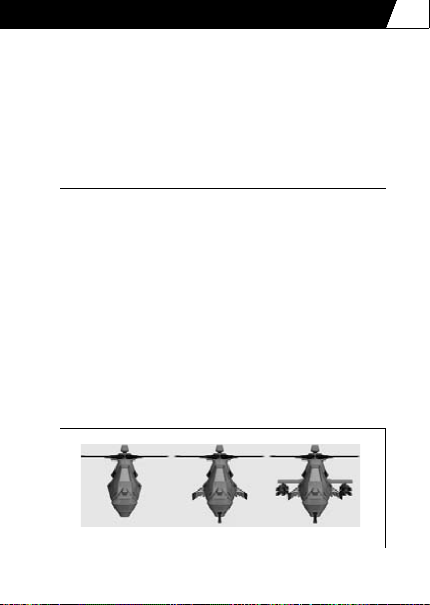
COMANCHE COCKPITS
Pan
Pan the HIDSS left, right up and down (use with g to pan the virtual cockpit view).
Next/previous target
Cycle forwards or backwards through the targets.
Lock/unlock target
Lock the current target to prevent the HIDSS from selecting another target.
Switch off
Switch the HIDSS target acquisition mode off.
Weapons
The Comanche is ‘mission agile’ and is configurable from a low observable scout to an
attack/precision strike gunship.
The Comanche carries its weapons internally, mounted on bay doors either side of the
fuselage. Optional stub wings can be fitted to carry more weapons.
When the stub wings are fitted the Comanche loses its stealth capabilities and so the stub
wings should not be used for low observable missions.
Selecting any internal weapon will automatically open the bay doors.
Selecting a weapon automatically switches the HIDSS display to combat mode. Making the
weapons safe returns the HIDSS display to navigation mode.
i Select next weapon
m+ i Select previous weapon
l+ i Weapons safe
To fire a weapon press the n. If the weapon fails to launch check the lock failure status
on the HIDSS display.
4.30
Low observable Integral armement Attack/precision strike
Diagram 4.23: The Comanche is configurable from a low observable scout to an
attack/precision strike gunship
Page 83

4.31
COMANCHE COCKPITS
20 mm Gatling Gun
The Comanche is equipped with a stowable three-barrel M197 20 millimetre Gatling gun
loaded with 500 rounds of ammunition.
The gun automatically tracks the selected target and can be rotated +/-120 degrees in
azimuth (left or right) and from +10 to -60 degrees in elevation (up or down).
The Gatling gun can be used against ground or air targets.
Type 20 mm Gatling gun
Rate of fire 750 rounds per minute
Maximum range 1,600 metres
Muzzle velocity 884 metres per second
Weight 0.257 Kg
Target marker
without valid lock
Target out
of range
Diagram 5.24: HIDSS display for the gun showing an out of range target
Target marker
with valid lock
Diagram 5.25: HIDSS display for the gun showing a valid target lock
Page 84

COMANCHE COCKPITS
AIM-92 Stinger
The Comanche carries Stinger short-range air-to-air guided missiles. A maximum of 12 can
be carried internally on the bay doors and a maximum of 16 can be carried on the stub
wings – 28 Stingers in total.
The Stinger is a heat seeking missile and is effective against airborne targets. If a ground
target is selected then "INVALID TARGET" is displayed on the HIDSS display.
Enemy targets will use flares and IR jammers to distract this missile.
Type short-range air-to-air
Guidance infra-red homing (fire-and-forget)
Maximum range 5,000 metres
Cruise speed Mach 2.0
Seeker field of view 80°
Weight 13.6 Kg
When the Stinger is seeking for a target a pair of dashed concentric circles move around the
HIDSS display to indicate the seeker head position. When a valid lock on has been achieved
the dashed circles become solid and indicate the target position. Also a tone is emitted to
indicate the valid lock.
4.32
Seeker head
position
Turn left to get
a target lock
Diagram 4.26: HIDSS display for a Stinger seeking a target
Diagram 4.27: HIDSS display for a Stinger showing a valid target lock
Current target
is outside the
seeker limit
Target marker
Page 85

4.33
COMANCHE COCKPITS
Hellfires
The Comanche carries Hellfire short-range anti-tank guided missiles. A maximum of 6 can
be carried internally on the bay doors and a maximum of 8 can be carried on the stub wings
– 14 Hellfires in total.
There are two types of Hellfire missile; the AGM-114L Longbow Hellfire and the AGM-114K
Hellfire II. Hellfires are effective against armoured battlefield targets but may also be used
against slow moving airborne targets.
The AGM-114L Longbow Hellfire is an active radar guided missile. This is fire and forget
missile. When the missile has been launched you can select another target and launch
another missile.
The AGM-114K Hellfire II is a semi-active laser guided missile. The missile requires a the
target to be 'painted' with laser.
Hellfire missiles can be launched in one of two modes; lock on before launch (LOBL) and
lock on after launch (LOAL). The lock on mode is toggled with the L key.
In LOBL mode the missile requires a line of sight to the target. If a radar guided Hellfire is
used then the helicopter can mask behind cover after the missile is launched. If a laser
guided Hellfire is used then the target must be laser designated throughout the missiles
flight. The missile's time to target (in seconds) is shown in the lower left corner of the
IHADSS display. If more than one missile is launched then the flight time of the most
recently launched missile is shown.
In LOAL mode the missiles can be launched from behind cover. The missile follows a high
launch profile. When a target is selected the missile steers towards it but only if the target
is within the missile's seeker limits. With radar guided Hellfires it is not necessary for the
helicopter to unmask but with laser guided missiles it is necessary to unmask in order to
designate the target.
Hellfire ‘LOAL’ Deployment
When Hellfire missiles are deployed in lock-on after launch ‘LOAL’ mode they follow a
high launch profile. That is, they zoom climb to about 300m before pitching over so
that they can 'see' ground targets.
The initial zoom climb uses energy and shortens the effective range of the missile. The
missile cannot see ground targets until it has pitched over and is looking towards the
ground. This increases the minimum range of the missile.
The target lock type will show a ‘VALID LOCK’ in LOAL mode if the target range is
between 1.5 Km and 5.0 Km. These are a guideline only. Other factors have to be
considered such as the height difference (between the helicopter and the target) and
the target azimuth error (the horizontal angular error between the display centre and
the target).
Page 86

COMANCHE COCKPITS
Type short-range anti-tank guided missile (ATGM)
Guidance active radar (AGM-114L) semi-active laser (AGM-114K)
Maximum range 8,000 metres
Cruise speed Mach 1.3
Seeker field of view 60°
Weight 45.0 Kg
Target marker
showing invalid
target lock
Lock on before
launch
Diagram 4.28: HIDSS display for a Hellfire missile in LOBL launch mode
showing an invalid target lock
4.34
Target marker
showing invalid
Lock on before
launch
Missile’s time to
target (seconds)
Diagram 4.29: IHIDSS display for a Hellfire missile in LOBL launch
mode showing a valid target lock
lock
Page 87

4.35
COMANCHE COCKPITS
Invalid target lock
Lock on after
launch
Diagram 4.30: HIDSS display for a Hellfire missile in LOAL launch mode
showing an invalid target lock
Target marker
Lock on after
launch
Valid target lock
Diagram 4.31: HIDSS display for a Hellfire missile in LOAL launch mode
showing a valid target lock
Page 88

COMANCHE COCKPITS
Hydra 70 Rockets
The Comanche carries Hydra 70 mm folding-fin aerial rockets (FFARs). These rockets are
unguided so it is necessary to boresight the target by steering the helicopter towards it. Use
the forward cockpit view o.
Hydra rockets can only be carried on the stub wings and they are mounted in pods of 19
giving a maximum capacity of 38.
Rockets can be fired in salvos to increase the damage area and kill probability.
S Increase salvo size
m+ S Decrease salvo size
There are two types of warheads; the M255 high explosive (HE) warhead and the M261
multi-purpose sub-munition (MPSM) warhead.
The M255 HE warhead is effective against soft battlefield targets and helicopters. The
M261 MPSM warhead is effective against armoured vehicles.
The rocket pods have automatic adjustable elevation (from +4.9 degrees to -15.0 degrees).
It is only necessary to line the helicopter's heading up with the target if the elevation is
within limits. This makes using rockets in the Comanche far easier than in the Hokum and
the kill probability is increased.
The rocket pods will not elevate at speeds in excess of 100 knots. If the helicopter's speed
is above this limit the rockets must be boresighted manually as in the Hokum.
Type folding-fin aerial rocket
Maximum range 5,000 metres
Weight 6.0 Kg
The HIDSS display shows the target marker and an 'I-beam'. It is necessary to line up the
target marker with the I-beam in order to get a valid lock. With airborne targets the I-beam
must be lined up with the computed intercept point instead.
4.36
Page 89

4.37
COMANCHE COCKPITS
Target marker
Rocket salvo size
Diagram 4.32: HIDSS display for unguided rockets showing I-beam not lined up
with ground target
Solid I-beam
indicating valid lock
➝
Steer towards
I-beam
Dashed I-beam
marker indicating
no boresight
Target marker
Diagram 4.33: HIDSS display for unguided rockets showing I-beam lined
up with ground target
Target marker
Dashed I-beam
Computed
intercept point
indicating
no boreshight
➝
Steer towards
I-beam
Diagram 4.34: HIDSS display for unguided rockets showing I-beam not lined up
with air target intercept point
Page 90

COMANCHE COCKPITS
Target marker
Computerised
intercept point
Solid I-beam
indicating
valid lock
Diagram 4.35: HIDSS display for unguided rockets showing I-beam lined up
with air target intercept point
Countermeasures
When the ASE display indicates a radar or infra-red threat then the following
countermeasures may be used to increase survivability.
Radar Jammer
The radar jammer is used to fool enemy radar of the helicopter’s position by creating
spurious targets.
J radar jammer on/off
IR Jammer
The IR jammer pumps out intense IR radiation to confuse the seeker head of an
incoming IR missile to break lock.
I IR jammer on/off
Chaff
Chaff comprises millions of strips of aluminised Mylar film which when released
generate a cloud of radar signature to fool incoming radar guided missiles.
C release chaff cartridge
Flares
Flares are hot pyrotechnic cartridges used to create false targets for incoming IR
missiles.
F release flare cartridge
The disadvantage of electronic countermeasures (ECM) such as the radar and IR jammers
is that they unmask the helicopter and increase its visibility. They should be used as
required.
The disadvantage of chaff and flares is that they run out! The Comanche carries 60 of each.
4.38
Page 91

4.39
COMANCHE COCKPITS
Automatic Countermeasures
The Co-pilot/Gunner can assist you with operating the countermeasures.
This option is selected in the Options Screen ‘Realism’ menu and can also be changed
in-flight.
l+ C automatic countermeasures on/off.
Pilot Night Vision Sensor (PNVS)
The Comanche pilot has night vision sensor to aid flying at night.
N PNVS on/off
Windshield Wipers
The Comanche is not fitted with windshield wipers as they would spoil the stealth
characteristics of the helicopter. In wet weather conditions concealed air blowers
automatically engage to clear the windshield.
Page 92

5. HOKUM COCKPITS
Page 93

HOKUM COCKPITS
5.1
Diagram 5.1: Cockpit view (pilot left, co-pilot right)
Diagram 5.2: Side-by-side cockpit configuration
Page 94

HOKUM COCKPITS
Instrument Panel
The Hokum has a side-by-side cockpit configuration. The pilot sits in the left (port) seat
and the co-pilot (CP/G) sits in the right (starboard) seat. You can assume either of the
crew roles.
Each pilot has two multi-function displays (MFDs). The indicator lights and backup
instruments are located on the central console. The co-pilot has binoculars for the ventrally
mounted periscope.
Refer to the In-flight ‘Views’ section for details of the cockpit views.
Airspeed Indicator
The airspeed indicator shows the indicated airspeed of the helicopter and also the sideslip
(sideways velocity).
5.2
Indicated Airspeed
Scale km/h * 10
Full scale deflection -50 to 450 km/h
Sideslip
Scale km/h * 10
Full scale deflection +/-100 km/h
Barometric Altimeter
The barometric altimeter shows the barometric altitude (height above sea level).
Barometric Altitude
Large needle scale metres X 100 (one revolution = 1,000 metres)
Small needle scale metres X 1,000 (one revolution = 10,000 metres)
Page 95

HOKUM COCKPITS
5.3
Vertical Speed Indicator
The vertical speed indicator shows the rate of climb.
Climb
10
5
20
030
520
10
Descend
Diagram 5.3: Direction of climb and descent
Rate of Climb
Scale metres per minute / 10 (scale is non-linear)
Full scale deflection +/-300 metres per minute
Artificial Horizon
The artificial horizon shows the helicopter pitch and roll attitude relative to the ground.
Pitched up Rolled left
Pitched down Rolled right
Diagram 5.4: Pitch up/down rolled left/right
Page 96

HOKUM COCKPITS
Standby Compass
The standby compass shows the helicopter’s heading.
90 East
‘C’ North
18 South
27 West
Master Caution Light
The master caution light flashes, accompanied by an audible warning, to indicate that there
is a problem. The problem will be indicated by the warning lights or EKRAN Display. To
acknowledge the caution press M. This extinguishes the master caution light and silences
the audible warning.
5.4
Fire Warning & Extinguisher Lights
The fire warning lights indicate if either engine or the auxiliary power unit (APU) is on fire.
In case of a fire use the fire extinguisher. The fire extinguisher can only be used once per
mission.
L ENG Left engine fire
APU APU fire
R ENG Right engine fire
l+ F Activate fire extinguisher
The fire extinguisher light indicates if the fire extinguishers have been used.
Page 97

HOKUM COCKPITS
5.5
Warning Lights
TRQ Engine over torque
RTR RPM Low main rotor RPM
FUEL LOW Low fuel level (<25% maximum fuel level)
HYD PRES Low hydraulic pressure
OIL PRES Low or high engine oil pressure
OIL TEMP High engine oil temperature
Status Lights
RTR BRK Rotor brake engaged
WHL BRK Wheel brake engaged
NAV LTS Navigation lights on
HOV HLD Hover-hold active
ALT HLD Altitude-hold active
AUT PLT Auto-pilot active
RDR Radar active
LSR Laser active
RDR JAM Radar jammer active
IR JAM Infra-red jammer active
AUT C/M Auto-countermeasures active
AUT TWD TWD auto-paging active
Gear (Undercarriage) Lights
The GEAR UP/DOWN light is illuminated green when the gear is fully down and red when
the gear is fully up. The light flashes when the gear is in a transitional state (raising or
lowering). The GEAR DAMAGED light indicates a gear failure.
l+ G Raise/lower gear
Page 98

HOKUM COCKPITS
EKRAN Display
The EKRAN automatic check-up system monitors necessary systems and critical values and
shows text warnings on this display and sends audible warnings to the pilot’s headphones.
Multi-Function Displays (MFDs)
Each pilot has two multi-function displays (MFDs) available.
Each MFD can display one of ten selectable pages:-
Ground Radar
Air Radar
Electro-Optical System (EOS)
Tactical Situation Display (TSD)
Threat Warning Display (TWD)
Weapon
System
Engine
Flight
Mission
5.6
The pages can be cycled through on each MFD:-
( Select next left MFD page
m+ ( Select previous left MFD page
) Select next right MFD page
m+ ) Select previous right MFD page
The displays can be switched on and off:-
l+ ( Switch left MFD on and off
l+ ) Switch right MFD on and off
Page 99

HOKUM COCKPITS
5.7
There are shortcut keys to select any page on either MFD.
Left MFD:-
l+ 1 Ground Radar
l+ 2 Air Radar
l+ 3 Electro-Optical System (EOS)
l+ 4 Tactical Situation Display (TSD)
l+ 5 Threat Warning Display (TWD)
l+ 6 Weapon
l+ 7 System
l+ 8 Engine
l+ 9 Flight
l+ 0 Mission
Right MFD:-
g+ 1 Ground Radar
g+ 2 Air Radar
g+ 3 Electro-Optical System (EOS)
g+ 4 Tactical Situation Display (TSD)
g+ 5 Threat Warning Display (TWD)
g+ 6 Weapon
g+ 7 System
g+ 8 Engine
g+ 9 Flight
g+ 0 Mission
Ground Radar MFD
See the 'Acquiring Targets' section.
Air Radar MFD
See the 'Acquiring Targets' section.
Electro-Optical System (EOS) MFD
See the 'Acquiring Targets' section.
Page 100

HOKUM COCKPITS
Tactical Situation Display (TSD) MFD
5.8
Sensor type
Threat range
circles
Selected target
Helicopter datum
Diagram 5.5: TSD MFD (target declutter)
Threat is targeting
helicopter (Flashes when
a missile is launched)
TSD range
Declutter level
(target)
Radar scan limits
Targets/Threats
Selected Target
range
The Tactical Situation Display shows the moving map, navigation information, targets, antiaircraft threats and air threats and is essential during combat situations.
Helicopter Datum
The TSD shows a plan view of the battlefield with the helicopter located at the bottom
of the display.
Declutter Level
The TSD has 3 declutter levels:-
ALL Display both target and navigation information
TGT Display target information only
NAV Display navigation information only
D Next TSD declutter level
m+ D Previous TSD declutter level
TSD Range
The TSD range is selectable between 2, 5, 10 and 25Km. This also changes the range
of the TWD display.
E Next TSD range
m+E Previous TSD range
 Loading...