


 Back
Back
OPERATOR'S MANUAL
COLOR LCD
SEARCHLIGHT SONAR
MODEL CH-270
www.furuno.co.jp

The paper used in this manual is elemental chlorine free.
FURUNO Authorized Distributor/Dealer
9-52 Ashihara-cho,
Nishinomiya, 662-8580, JAPAN
Telephone : +81-(0)798-65-2111
Fax |
: +81-(0)798-65-4200 |
All rights reserved. |
Printed in Japan |
A : JUN. 2003
D : JUN. 03, 2010
Pub. No. OME-13220-D
(DAMI ) CH-270
*00014699513*
*00014699513*
* 0 0 0 1 4 6 9 9 5 1 3 *

IMPORTANT NOTICES
•This manual is intended for use by native speakers of English.
•No part of this manual may be copied or reproduced without written permission.
•If this manual is lost or worn, contact your dealer about replacement.
•The contents of this manual and equipment specifications are subject to change without notice.
•The example screens (or illustrations) shown in this manual may not match the screens you see on your display. The screen you see depends on your system configuration and equipment settings.
•Store this manual in a convenient place for future reference.
•FURUNO will assume no responsibility for the damage caused by improper use or modification of the equipment (including software) by an unauthorized agent or a third party.
•When it is time to discard this product it must be done according to local regulations for disposal of industrial waste. For disposal in the USA, refer to the Electronics Industries Alliance (http://www.eiae.org/).
i


 SAFETY INSTRUCTIONS
 WARNING
ELECTRICAL SHOCK HAZARD
Do not open the equipment.
Only qualified personnel should work inside the equipment.
Immediately turn off the power at the switchboard if water leaks into the equipment or something is dropped in the equipment.
Continued use of the equipment can cause fire or electrical shock. Contact a FURUNO agent for service.
Do not disassemble or modify the equipment.
Fire, electrical shock or serious injury can result.
Immediately turn off the power at the switchboard if the equipment is emitting smoke or fire.
Continued use can cause fatal damage to the equipment. Contact a FURUNO agent for service.
Make sure no rain or water splash leaks into the equipment.
Fire or electrical shock can result if water leaks in the equipment.
 WARNING
Keep heater away from equipment.
A heater can melt the equipment's power cord, which can cause fire or electrical shock.
Use the proper fuse.
The fuse in the hull and transceiver units protects them from overcurrent, equipment fault and reverse polarity of the ship's mains. If a fuse blows replace it with fuse of the same amperage. Use of a fuse of different amperage can result in damage
to the equipment.
Retract the transducer before turning off the power.
Damage to the transducer may result unless it is retracted.
Wait until the transducer switch [↑] lights steadily and then turn off the power.
ii
 CAUTION
Do not exceed 20 knots when operating the equipment and do not exceed 15 knots when lowering or raising the transducer.
The transducer shaft may become damaged.
Do not use the equipment for other than its intended purpose.
Wrongful use of the equipment may result in personal injury or damage to the equipment.
WARNING LABELS
Warning labels are attached to the display, transceiver and hull units. Do not remove the labels. If a label is missing or illegible, contact a FURUNO agent or dealer.
 WARNING
To avoid electrical shock, do not remove cover. No user-serviceable parts inside.
 WARNING
Moving shaft can pinch and cut. Keep hands clear while operating. Lockout power before servicing.
Name: Warning Label (1)
Type: 86-003-1011-0
Code No.: 100-236-230
DISPLAY UNIT,
TRANSCEIVER
UNIT
Name: "Finger Catch"
Warning Label
Type: 06-021-4015-0
Code No.: 100-281-590
HULL UNIT
 CAUTION
WORKING WITH THE SONAR OIL
Precautions
Keep oil away from eyes. Wear protective goggles when working with the oil. The oil can cause inflammation of the eyes.
Do not touch the oil. Wear protective gloves when working with the oil. The oil can cause inflammation of the skin. Do not ingest the oil. Diarrhea and vomiting may result.
Keep the oil out of reach of children.
Emergency procedures
If the oil enters eyes, flush with clean water about 15 minutes. Consult a physician.
If the oil is ingested, see a physician immediately.
If the oil contacts skin, wash with soap and water.
Disposal of oil and its container
Dispose of oil and its container in accordance with local regulations. For further details, contact place of purchase.
Storage
Seal container to keep out foreign material. Store in dark, cool place.
TFT LCD
The high quality TFT (Thin Film Transistor) LCD displays 99.99% of its picture elements. The remaining 0.01% may drop out or light, however this is an inherent property of the LCD; it is not a sign of malfunction.
iii
TABLE OF CONTENTS
|
|
|
|
|
FOREWORD |
....................................................................................................................... |
vii |
||
SYSTEM CONFIGURATION ............................................................................................ |
ix |
|||
1. OPERATIONAL .......................................................................................OVERVIEW |
1-1 |
|
||
1.1 |
Control ....................................................................................................Description |
1-1 |
|
|
1.2 |
Remote .....................................................................................................Controller |
1-2 |
|
|
1.3 |
Turning ..........................................................................................the Power On/Off |
1-3 |
|
|
|
1.3.1 ........................................................................................................ |
Power on |
1-3 |
|
|
1.3.2 ........................................................................................................ |
Power off |
1-4 |
|
1.4 |
Raising, .............................................................................Lowering the Transducer |
1-5 |
|
|
|
1.4.1 ................................................................................. |
Lowering the transducer |
1-5 |
|
|
1.4.2 .................................................................................... |
Raising the transducer |
1-5 |
|
1.5 |
Choosing ...................................................................................................a Display |
1-6 |
|
|
1.6 |
Adjusting ................................................................Screen Brilliance, Panel Dimmer |
1-7 |
|
|
1.7 |
Adjusting .....................................................................................................the Gain |
1-7 |
|
|
1.8 |
Basic ...............................................................................................Menu Operation |
1-8 |
|
|
2. HORIZONTAL MODE.................................................................................................. |
2-1 |
|
2.1 |
Operational Overview................................................................................................ |
2-1 |
2.2 |
Typical Horizontal Mode Display ............................................................................... |
2-2 |
2.3 |
Choosing the Range.................................................................................................. |
2-3 |
2.4 |
Choosing Sector Width.............................................................................................. |
2-4 |
2.5 |
Choosing Train Center .............................................................................................. |
2-5 |
2.6 |
Choosing the Tilt Angle ............................................................................................. |
2-6 |
|
2.6.1 Choosing the tilt angle .................................................................................... |
2-6 |
|
2.6.2 Relation between tilt angle and echo .............................................................. |
2-7 |
|
2.6.3 Tilt angle for surface fish................................................................................. |
2-8 |
|
2.6.4 Suitable tilt angle ............................................................................................ |
2-9 |
2.7 |
Choosing the Training Speed ................................................................................... |
2-10 |
2.8 |
Finding Echo Position with the Cursor...................................................................... |
2-10 |
2.9 |
Event Marker............................................................................................................ |
2-11 |
|
2.9.1 Inscribing the event marker............................................................................ |
2-11 |
|
2.9.2 Deleting all event markers.............................................................................. |
2-12 |
2.10 |
Depth and Horizontal Range Markers....................................................................... |
2-12 |
2.11 |
Adjusting the Picture ................................................................................................ |
2-13 |
|
2.11.1 Suppressing bottom and surface reflections .................................................. |
2-13 |
|
2.11.2 Suppressing bottom tail ................................................................................. |
2-14 |
|
2.11.3 Displaying weak echoes clearly .................................................................... |
2-14 |
|
2.11.4 Erasing weak echoes..................................................................................... |
2-17 |
|
2.11.5 Enlarging fish echoes (horizontal expansion display) ..................................... |
2-18 |
2.12 |
Target Lock .............................................................................................................. |
2-19 |
|
2.12.1 Choosing target lock mode ............................................................................ |
2-19 |
|
2.12.2 Manual reverse mode .................................................................................... |
2-19 |
|
2.12.3 Position mode................................................................................................ |
2-20 |
|
2.12.4 Echo mode .................................................................................................... |
2-21 |
iv
|
|
TABLE OF CONTENTS |
2.13 |
Horizontal Menu Overview....................................................................................... |
2-23 |
2.14 Interpreting the Horizontal Display ........................................................................... |
2-25 |
|
|
2.14.1 How the horizontal mode picture is painted ................................................... |
2-25 |
|
2.14.2 Sample echo displays ................................................................................... |
2-26 |
|
2.14.3 Combination display examples...................................................................... |
2-30 |
3. VERTICAL SCAN MODE............................................................................................. |
3-1 |
|
3.1 |
Operational Overview ................................................................................................ |
3-1 |
3.2 |
Displaying Vertical Scan Mode Display...................................................................... |
3-2 |
|
3.2.1 Typical vertical scan mode display .................................................................. |
3-2 |
|
3.2.2 How the vertical scan picture is painted........................................................... |
3-3 |
|
3.2.3 Horizontal/vertical scan display ....................................................................... |
3-4 |
3.3 |
Choosing the Range.................................................................................................. |
3-6 |
3.4 |
Choosing Train Center............................................................................................... |
3-6 |
3.5 |
Choosing Display Sector............................................................................................ |
3-7 |
3.6 |
Choosing Sector Center............................................................................................. |
3-8 |
3.7 |
Choosing the Tilt Speed............................................................................................. |
3-9 |
3.8 |
Finding Echo Position with the Cursor ....................................................................... |
3-9 |
3.9 |
Event Marker ........................................................................................................... |
3-10 |
|
3.9.1 Entering an event marker .............................................................................. |
3-10 |
|
3.9.2 Deleting all event markers............................................................................. |
3-11 |
3.10 |
Depth and Horizontal Range Markers...................................................................... |
3-11 |
3.11 |
Adjusting the Picture................................................................................................ |
3-12 |
|
3.11.1 Displaying weak echoes clearly..................................................................... |
3-12 |
|
3.11.2 Suppressing noise and interference .............................................................. |
3-14 |
|
3.11.3 Gain adjustment ............................................................................................ |
3-14 |
|
3.11.4 Resolution color ............................................................................................ |
3-15 |
|
3.11.5 Suppressing clutter........................................................................................ |
3-15 |
|
3.11.6 Choosing horizontal range expansion factor.................................................. |
3-16 |
3.12 |
Interpreting the Vertical Scan Display ...................................................................... |
3-17 |
|
3.12.1 Sample echo displays ................................................................................... |
3-17 |
4. ECHO SOUNDER MODE............................................................................................. |
4-1 |
|
4.1 |
Operational Overview ................................................................................................ |
4-1 |
4.2 |
Typical Echo Sounder Display ................................................................................... |
4-2 |
4.3 |
Choosing the Range.................................................................................................. |
4-3 |
4.4 |
Train Direction ........................................................................................................... |
4-4 |
4.5 |
Choosing Tilt Angle.................................................................................................... |
4-4 |
4.6 |
Choosing Picture Advance Speed ............................................................................. |
4-4 |
4.7 |
Measuring Range by Cursor ...................................................................................... |
4-5 |
4.8 |
Event Marker ............................................................................................................. |
4-5 |
|
4.8.1 Inscribing the event marker ............................................................................. |
4-6 |
|
4.8.2 Deleting all event markers............................................................................... |
4-6 |
4.9 |
Range Marker............................................................................................................ |
4-7 |
4.10 |
Adjusting the Picture.................................................................................................. |
4-8 |
|
4.10.1 Displaying weak echoes clearly....................................................................... |
4-8 |
|
4.10.2 Finding echo strength (A-scope display)........................................................ |
4-10 |
|
4.10.3 Gain adjustment ............................................................................................ |
4-11 |
v
TABLE OF CONTENTS
|
4.10.4 Resolution color ............................................................................................. |
4-11 |
|
|
4.10.5 Suppressing clutter ........................................................................................ |
4-12 |
|
5. MENU OPERATION .................................................................................................... |
5-1 |
||
5.1 |
COM1 Menu.............................................................................................................. |
5-1 |
|
|
5.1.1 Displaying the COM1 menu ............................................................................ |
5-1 |
|
|
5.1.2 |
COM1 menu description ................................................................................. |
5-1 |
5.2 |
COM2 Menu.............................................................................................................. |
5-2 |
|
|
5.2.1 Displaying the COM2 menu ............................................................................ |
5-2 |
|
|
5.2.2 |
COM2 menu description ................................................................................. |
5-2 |
5.3 |
Short-cut Menu, Preset Menu.................................................................................... |
5-3 |
|
|
5.3.1 Choosing short-cut or preset........................................................................... |
5-3 |
|
|
5.3.2 Changing setting of preset key........................................................................ |
5-5 |
|
|
5.3.3 Changing setting of short-cut key.................................................................... |
5-6 |
|
5.4 |
SYSTEM Menu ......................................................................................................... |
5-8 |
|
|
5.4.1 Displaying the SYSTEM menu........................................................................ |
5-8 |
|
|
5.4.2 SYSTEM SETTING 1 menu description.......................................................... |
5-9 |
|
|
5.4.3 SYSTEM SETTING 2 menu description......................................................... |
5-11 |
|
|
5.4.4 Sonar (horizontal) mode range settings ......................................................... |
5-13 |
|
|
5.4.5 Vertical scan mode range settings ................................................................. |
5-14 |
|
|
5.4.6 Echo sounder mode range settings................................................................ |
5-15 |
|
|
5.4.7 |
Track range settings ...................................................................................... |
5-16 |
|
5.4.8 |
Color palette .................................................................................................. |
5-17 |
|
5.4.9 |
Language ....................................................................................................... |
5-18 |
|
5.4.10 System backup .............................................................................................. |
5-18 |
|
|
5.4.11 Loading backup data...................................................................................... |
5-18 |
|
|
5.4.12 Transducer frequency adjustment.................................................................. |
5-19 |
|
|
5.4.13 Demonstration mode...................................................................................... |
5-19 |
|
|
5.4.14 Restoring all default settings.......................................................................... |
5-20 |
|
6. MAINTENANCE, TROUBLESHOOTING .................................................................... |
6-1 |
||
6.1 |
Preventive Maintenance............................................................................................ |
6-1 |
|
6.2 |
Cleaning the Equipment ............................................................................................ |
6-1 |
|
6.3 |
Hull Unit Maintenance ............................................................................................... |
6-2 |
|
|
6.3.1 |
Lubrication ...................................................................................................... |
6-2 |
|
6.3.2 Manually raising, lowering transducer ............................................................. |
6-2 |
|
6.4 |
Transducer Maintenance........................................................................................... |
6-3 |
|
6.5 |
Fuse Replacement .................................................................................................... |
6-3 |
|
6.6 |
Troubleshooting ........................................................................................................ |
6-4 |
|
6.7 |
Error Messages......................................................................................................... |
6-5 |
|
6.8 |
Diagnostics ............................................................................................................... |
6-6 |
|
6.9 |
Test Pattern............................................................................................................... |
6-8 |
|
MENU TREE |
.................................................................................................................... |
M-1 |
|
SPECIFICATIONS ......................................................................................................... |
SP-1 |
||
INDEX |
.............................................................................................................................. |
|
IN-1 |
vi

FOREWORD
Thank you for purchasing the CH-270 Color LCD Searchlight Sonar. We are confident you will discover why FURUNO has become synonymous with quality and reliability.
Dedicated in the design and manufacture of marine electronics equipment for more than half a century, FURUNO Electric Company has gained an unrivaled reputation as a world leader in the industry. This is the result of our technical excellence as well as our worldwide distribution and service network.
Please carefully read and follow the safety information and operating and maintenance instructions set forth in this manual before attempting to operate the equipment and conduct any maintenance. Your sonar will perform to the utmost of its ability only if it is operated and maintained in accordance with the correct procedures.
Features
The CH-270 displays underwater objects on a bright 10.4-inch color LCD display, in 8 (or 16) colors according to received echo strengths. Alternatively, the interface unit permits connection of a commercial CRT or LCD monitor to act as the main, backup or remote display. Operating frequency is 180 kHz.
The main features of the CH-270 are
•High definition active matrix color LCD.
•Target lock on a fish school or stationary position (reef, etc.).
•Audible detection of echoes frees the operator from continuous watch of the display.
•Compact display and hull units permit installation where space is limited.
•Interface IF-8000 permits use of a commercial monitor in lieu of FURUNO-supplied display unit.
•Automatic pulselength switching for optimum performance in short and long ranges.
•Eight operational modes: Horizontal, Horizontal Expansion, Vertical Scan, Echo Sounder, Horizontal/Vertical Scan, Horizontal/History, Horizontal/Video Plotter and Horizontal/Strata.
•Automatic retraction of transducer at operator-chosen ship’s speed between 5 and 15 knots.
•CUSTOM MODE keys provide one-touch setup of the equipment or short-cut key function.
•Tracing of ship’s track with connection of position-fixing equipment (GPS, etc.).
•One of the echo strengths may be displayed in white to enhance the specific echo level.
•The “Vertical Search” feature provides a cross-sectional view of the vertical plane, which is useful for evaluating fish school concentration.
vii
FOREWORD
Usage Precautions
•The Motion Sensor MS-100 compensates for ship’s pitching and rolling. However, it does not compensate for load unbalance. Use Clinometer BS-704 if compensation for load unbalance is required.
•If the equipment will not be used for a long time, shut off the power to it at the mains switchboard to prevent battery discharge.
•If the soundome is to be operated while the ship is dry-docked, set the transmitter output power to “MIN(imum),” on the COM1 menu. Damage to the train/tilt assy. may result if the transducer is operated with maximum transmitter power when the ship is dry-docked.
•When the ship is dry-docked check the soundome for signs of electrolytic corrosion. Find the reason for the corrosion and attach a zinc plate to the location as an anticorrosion measure.
viii
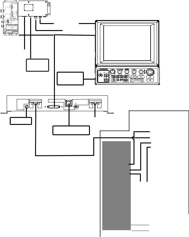
SYSTEM CONFIGURATION
CH-270 (350 stroke)
INTERFACE UNIT
IF-8000
|
|
DISPLAY UNIT MU-100C |
|||||
|
Navigator |
|
|
|
|
|
|
|
Control Unit |
|
|
|
|
|
|
Display |
|
|
|
|
|
|
|
Unit |
External |
|
|
|
|
|
|
|
|
|
|
|
|
|
|
|
Monitor |
|
|
|
|
|
|
|
|
XDR |
|
|
|
|
|
|
Remote |
GAIN |
SECTOR |
TRAIN |
RANGE |
TILT |
|
|
POWER |
|
MAIN |
FULL FAST |
BRILL |
TARGET MENU |
|
|
|
SUB |
HALF SCAN |
||||
|
|
|
|
||||
|
Controller |
|
|
|
|
|
R/B EVENT |
|
|
DISPLAY MODE |
|
CUSTOM MODE |
|
|
|
|
|
|
|
|
|
|
|
CONTROL UNIT CH-252
HULL UNIT |
DATA/VIDEO OUT |
|
12-32VDC |
TRANSCEIVER UNIT |
|
|
|||
SPEAKER |
|
MOTION SENSOR |
|
CH-273 |
Speaker |
|
|
12-32 VDC |
|
|
|
|
||
Motion Sensor
Note 1: The CH-270 is supplied with or without a display unit. For connection of locally supplied monitor, an interface unit is provided. The drawing above shows the system configuration with the MU-100C.
Note 2: For use of a locally supplied monitor, connect it and control unit to the interface unit.
HULL UNIT
CH-181
How to remove the hard cover
(system with locally supplied monitor only)
Place your thumbs at the locations shown with circles in the illustration at right, and then lift the cover while pressing it with your thumbs.
12/24 VDC
:Standard
:Option
:Local Supply
ix
SYSTEM CONFIGURATION |
|
|
|
|
|
|
CH-270 (250 stroke) |
|
|
|
|
|
|
INTERFACE UNIT |
|
|
|
|
|
|
IF-8000 |
|
|
|
|
|
|
|
DISPLAY UNIT MU-100C |
|||||
Navigator |
|
|
|
|
|
|
Control Unit |
|
|
|
|
|
|
DIsplay Unit |
|
|
|
|
|
|
External |
|
|
|
|
|
|
Monitor |
|
|
|
|
|
|
Remote |
XDR |
|
|
|
|
|
POWER |
SECTOR |
SUB |
HALF SCAN |
TILT |
|
|
|
GAIN |
TRAIN |
RANGE |
|
||
|
|
|
MAIN FULL FAST |
BRILL |
TARGET MENU |
|
Controller |
|
|
|
|
||
|
|
|
|
|
R/B EVENT |
|
|
|
DISPLAY MODE |
|
CUSTOM MODE |
|
|
|
CONTROL UNIT CH-252 |
|||||
HULL UNIT |
DATA/VIDEO OUT |
12-32VDC |
TRANSCEIVER UNIT |
SPEAKER |
MOTION SENSOR |
|
CH-273 |
CONTROL BOX
Speaker |
12-32 VDC |
|
Motion Sensor
Note 1: The CH-270 is supplied |
|
|
||
with or without a display |
|
|
||
unit. For connection of |
|
|
||
locally supplied monitor, an |
12/24 VDC |
|||
interface unit is provided. |
||||
The drawing above shows |
|
|
||
the system configuration |
|
HULL UNIT |
||
with the MU-100C. |
|
|||
|
|
|
|
CH-184 |
Note 2: For use of a locally |
|
|
|
|
|
|
: Standard |
||
supplied monitor, connect |
|
|
||
|
||||
it and control unit to the |
|
|
: Option |
|
interface unit. |
|
|
: Local Supply |
|
|
|
|
|
|
x
1. OPERATIONAL OVERVIEW
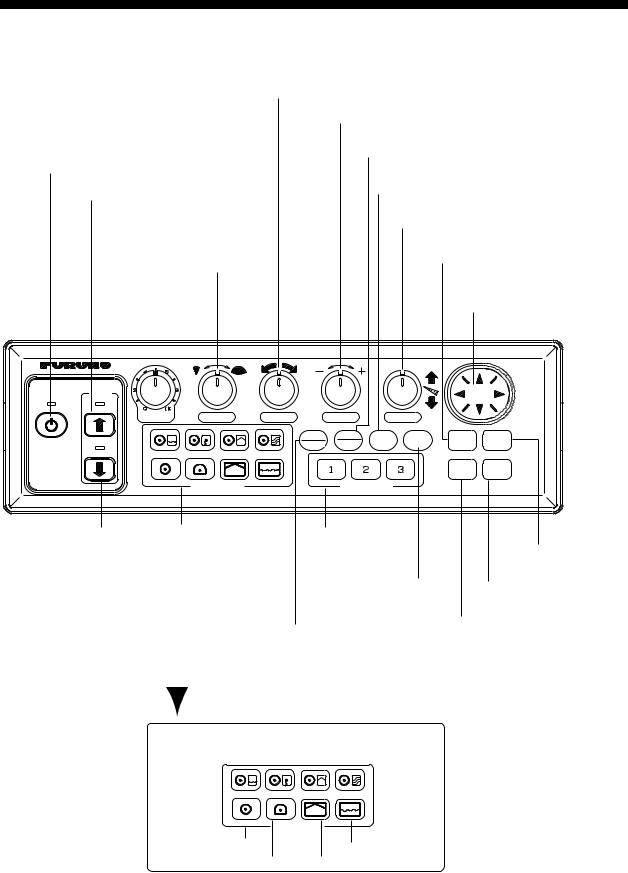
1.1Control Description
|
|
Chooses center bearing of training sector. |
|
|
|
Chooses detection range. |
|
|
|
Switches training sector between 180° and 360°. |
|
|
|
(horizontal mode), or 180° (vertical scan mode). |
|
Turns the power on/off. |
Chooses scan speed (sonar)/picture |
||
|
|
||
Raises the transducer. |
advancement speed (echo sounder). |
||
|
|||
Adjusts receiver |
= Controls tilt angle. |
||
= Selects center direction of |
|||
sensitivity. |
|||
the vertical scanning sector. |
|||
|
Chooses width of |
||
|
|||
|
Turns target lock on/off. |
||
|
training sector. |
||
|
|
||
|
|
Omnipad |
|
|
|
= Shifts cursor. |
|
|
|
= Selects menu items, options. |
|
|
|
|
|
XDR
GAIN |
SECTOR |
TRAIN |
RANGE |
TILT |
|
MAIN |
FULL |
FAST |
BRILL |
TARGET |
MENU |
|
POWER |
SUB |
HALF |
SCAN |
||||
|
|
|
|||||
|
|
|
|
|
R/B |
EVENT |
|
|
DISPLAY MODE |
CUSTOM MODE |
|
|
|
||
Lowers the transducer. |
Choose display mode. |
|
Provide short-cut |
|
|||||
|
|
|
|
|
|
|
key or one-touch |
Opens/closes |
|
|
|
|
|
|
|
|
setup. |
menu. |
|
|
|
|
|
|
|
|
Adjusts display |
Inscribes/erases event |
|
|
|
|
|
|
|
|
brilliance* and |
marker. |
|
|
|
|
|
|
|
|
panel dimmer. |
Inscribes/erases range |
|
|
|
|
|
|
|
|
|
|
|
|
|
|
|
|
|
Swithes control between |
and bearing markers. |
||
|
|
|
|
|
|
main and sub windows in |
|
||
|
|
|
|
|
|
combination displays. |
* FURUNO |
||
|
|
|
|
|
|
Sub window is circumbscribed |
|||
|
|
|
|
|
|
monitor |
|||
|
|
|
|
|
|
with a red rectangle when it |
|||
|
|
|
|
|
|
only. |
|||
|
|
|
|
|
|
||||
|
|
|
|
|
|
is selected. |
|||
|
|
|
|
|
|
|
|||
|
Horizontal/Video Plotter |
Horizontal/Vertical Scan |
|
||||||
|
Horizontal/History |
|
|
Horizontal/Strata |
|
||||
|
|
|
|
|
|
|
|
|
|
DISPLAY MODE |
|
Horizontal |
Echo Sounder |
Horizontal Expansion |
Vertical Scan |
Control unit
1-1
1. OPERATIONAL OVERVIEW
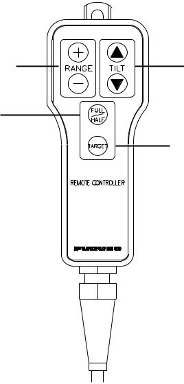
1.2Remote Controller
The Remote Controller CH-256 (option) provides armchair control over range, tilt, target lock and training range.
Choose display range.
Chooses training range.
for full circle 360° (horizontal mode)
or half circle 180° (vertical scan mode).
Choose tilt angle.
Enables/disables target lock.
Remote controller
Note: The remote controller can also be used with a commercial monitor.
1-2

1. OPERATIONAL OVERVIEW
1.3Turning the Power On/Off
1.3.1Power on
Press the [POWER] switch on the control unit until you hear a “click.” A beep sounds, the lamp above the switch lights and the startup display appears (for four seconds).
M O D E L : C H - 2 7 0 1 8 0 k H z
Startup display
Note 1: Wait at least five seconds before reapplying the power.
Note 2: The first time the power is applied after installation, the language selection screen appears. English is selected; press the [MENU] key to erase the screen and continue.
Please set language.
([p/q]: Select, [MENU]: Enter)
XXXX ... For Japanese Customer
XXXX
English
(Japanese)
Language selection screen
Note 3: The example screens shown in this manual may not match the screens you see on your display. The screen you see depends on your system configuration and equipment settings.
1-3
1. OPERATIONAL OVERVIEW
1.3.2Power off
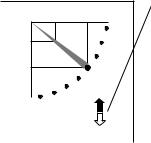
1.Press the [©] switch on the control unit. The lamp above the switch blinks while the transducer is being raised and lights steadily when it is fully raised.
|
30 |
Transducer status indicator |
|
• Up arrow is filled when transducer |
|
|
|
|
|
|
has been retracted into the tank. |
25 |
|
• Down arrow is filled when transducer |
|
has been fully lowered. |
|
|
|
• Appropriate arrow flashes during |
|
|
raising/lowering of transducer. |
NOTE: When the transducer is being raised automatically (auto raise feature), the arrows are filled and the up arrow flashes. When the transducer has been fully retracted, the up arrow lights
and the down arrow becomes hollow.
Transducer status indicator
2. Press the [POWER] switch after the lamp above the [©] switch lights steadily.
Note 1: The transducer is automatically retracted into the tank if the [POWER] switch is pressed before retracting the transducer. However, for safety purposes, make it a habit to retract the transducer before turning off the power.
Note 2: After changing settings, wait at least one minute before turning off the equipment to allow the equipment to memorize settings. This will enable the equipment to start up with the last-used settings. No harm will result to the equipment if this is not done.
Note 3: The hull unit remains powered when power is turned off at the control unit. Therefore, if the sonar is not to be used for a long period turn it off at ship’s mains switchboard.
1-4

1. OPERATIONAL OVERVIEW
1.4Raising, Lowering the Transducer
1.4.1Lowering the transducer
With the boat at the fishing ground, press the [ª] switch to lower the transducer. The lamp above the switch blinks while the transducer is being lowered and lights when it is completely lowered. The down arrow on the transducer status indicator is filled when the transducer is completely lowered.
 CAUTION
Do not exceed 20 knots when operating the equipment and do not exceed 15 knots when lowering or raising the transducer.
The transducer may become damaged.
1.4.2Raising the transducer
Press the [©] switch to raise the transducer. The lamp above the switch blinks while the transducer is being raised and lights steadily when it is fully raised. The up arrow of the transducer status indicator is filled when the transducer is fully raised.
Note 1: With speed input, the transducer can be automatically raised when the ship’s speed exceeds a speed between 5 and 15 knots. For further details about the automatic retraction feature, see AUTO RETRACTION in paragraph 5.4.3.
Note 2: Audio and visual alarms may be released when ship speed goes higher than allowed for a certain transducer operation. For further details, see SPEED ALARM MESSAGE in paragraph 5.4.3.
1-5

1. OPERATIONAL OVERVIEW
1.5Choosing a Display
This sonar has eight display modes and you may choose one with one of the DISPLAY MODE keys. Refer to the chapter shown in the illustration for more information about each mode.
Key |
Picture |
Key |
Picture |
|
NAV |
|
NAV |
|
DATA |
|
DATA |
|
HORIZONTAL |
|
HORIZONTAL EXPANSION |
|
This mode provides 360 degree coverage. |
|
Zoomed horizontal picture appears over |
|
Useful for general search. (Chapter 2) |
|
the entire screen. (Chapter 2) |
NAV |
NAV |
DATA |
DATA |
|
or |
|
A-SCOPE |
|
DISPLAY |
|
Water temp/depth |
|
VERTICAL SCAN |
ECHO SOUNDER |
|||||||||||||||
|
|
|
|
|
|
|
|
|
|
|
|
|
|
|
|
|
|
Vertical section of underwater conditions |
Using a fixed spot beam this display |
||||||||||||||||
appears on the entire screen. (Chapter 3) |
shows fish echoes below or around the |
||||||||||||||||
|
|
|
|
|
|
|
|
|
vessel. (Chapter 4) |
||||||||
|
|
|
|
|
|
|
|
|
|
|
|
|
|
|
|
|
|
|
|
|
|
|
|
|
|
|
|
|
|
|
|
|
|
|
|
NAV DATA |
NAV DATA |
|
HORIZONTAL/HISTORY |
HORIZONTAL/VIDEO PLOTTER |
|||
|
|
|
|
|
|
The horizontal picture appears in the main |
The horizontal picture appears in the main |
||||
window; the history picture in the sub |
window and the video plotter picture, which |
||||
window. Useful for showing history of fish |
traces ship's track, in the sub window. |
||||
movement, distribution. (Chapter 2) |
(Chapter 2) |
||||
NAV DATA |
NAV DATA |
HORIZONTAL/VERTICAL SCAN |
HORIZONTAL/STRATA |
The horizontal picture appears in the main |
The horizontal picture appears in the main |
window; the vertical scan picture in the sub |
window; the strata picture in the sub window. |
window. Note that the vertical scan display |
The strata picture shows bottom undulatons |
may be located below the horizontal |
in different colors. It is useful in bottom |
display, with both displays nearly equal |
trawling to avoid projections. (Chapter 2) |
in size. (Chapter 3) |
|
Display modes
1-6

1. OPERATIONAL OVERVIEW
1.6Adjusting Screen Brilliance, Panel Dimmer
Screen brilliance can be adjusted in nine levels and the panel dimmer (backlighting) in four.
1.Press the [BRILL] key to open the dialog box for screen brilliance and panel dimmer. Do the next step within four seconds; otherwise the dialog box will be erased.
BRILL:3
DIMMER:3
Brilliance, panel dimmer dialog box
2.Operate ◄ or ► to adjust screen brilliance (0 is the lowest brilliance; 9 the highest). The [BRILL] key may also be operated to adjust brilliance.
3.Operate ▲ or ▼ to adjust the panel dimmer (0 is the lowest level; 4 is the highest).
4.Press the [MENU] key to register settings and close the dialog box. Note that the dialog box is automatically erased if there is no control operation within about four seconds.
Note: The brilliance of a commercial monitor cannot be adjusted with the [BRILL] key. Use the associated control on the monitor.
1.7Adjusting the Gain
The [GAIN] control adjusts the sensitivity of the receiver. Normally, the control is adjusted so that the bottom echo is displayed in reddish-brown mixed with red. Initially set the gain between “4” and “6” and then fine tune according to fishing ground, etc.
Too Low |
Proper |
Too High |
How to adjust the gain
1-7

1. OPERATIONAL OVERVIEW
1.8Basic Menu Operation
The menu, consisting of seven menus, mostly contains items which once preset do not require frequent adjustment. Below is the procedure for basic menu operation.
1.Press the [MENU] key to open the menu. The last-used menu is displayed. (In the example below, the COM2 menu is shown.)
Note: Either PRESET or SHORT-CUT appears between ES and SYS at the top of the menu depending on the setting of CUSTOM KEY on the SYSTEM SETTING 1 menu. For further details, see paragraph 5.3.
|
|
MENU |
|
COM1 |
COM2 |
HORZ VERT ES PRESET SYS |
|
|||
|
|
DELETING TRACK |
NO |
|
|
|
|
|||
|
|
|
Dialog box appears here when |
|
|
|||||
|
|
WHITE MARKER |
OFF |
|
|
|
||||
|
|
|
a menu item is selected. |
|
|
|||||
|
|
SIG LEVEL |
|
OFF |
|
|
|
|||
|
|
|
|
|
|
|
||||
|
|
COLOR |
|
16 |
|
|
|
|
||
|
|
BKGD COLOR |
|
2 |
|
|
|
|
|
|
|
|
|
|
|
|
|
|
|
|
|
|
|
|
|
|
|
|
|
|
|
|
: SELECT |
: CHANGE MENU: END |
COM2 menu
2.To choose a menu, press ▲ to choose MENU at the top of the screen (if it is not already chosen) and then press ◄ or ► to choose menu desired.
3.Press ▲ or ▼ to choose menu item desired. Menu help is provided at the bottom of the screen.
4.Press ► to open the corresponding dialog box. The example below shows the dialog box for DELETING TRACK in the COM2 menu.
DELETING TRACK
NO YES
Dialog box for deleting track
5.Press ◄ or ► to choose option desired. If input of numeric data is required, use ◄ or ► to lower or raise the figure, respectively.
6.Press ▲ or ▼ to close the dialog box and return to the menu, or press the [MENU] key to register your selection and close the menu.
1-8
2. HORIZONTAL MODE
2.1Operational Overview
The figure below shows the typical horizontal mode operating sequence.
|
7. Set center bearing of train |
8. Set tilt angle. |
||||
|
|
sector. |
|
|
|
|
|
|
|
|
|||
|
|
|
|
|
|
|
6(a). Set scanning sector. |
|
5. Set range. |
|
|||
1. Turn on the power. |
|
|
|
|
11. Adjust menu settings |
|
9. Adjust gain. |
|
|
|
|
(ex. TVG) as required. |
|
|
|
|
|
|
|
|
|
|
|
|
|
|
|
XDR
GAIN |
SECTOR |
TRAIN |
RANGE |
TILT |
|
MAIN |
FULL |
FAST |
BRILL |
TARGET |
MENU |
|
POWER |
SUB |
HALF |
SCAN |
||||
|
|
|
|||||
|
|
|
|
|
R/B |
EVENT |
|
|
DISPLAY MODE |
CUSTOM MODE |
|
|
|
||
2. Lower the |
4. Select appropriate |
10. Measure range and |
|
horizontal mode. |
bearing to target with cursor. |
||
transducer. |
|||
6(b). Select training sector for |
3. Adjust screen |
||
|
|||
|
full circle. |
brilliance. |
Control unit
2-1
2. HORIZONTAL MODE
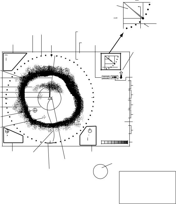
2.2Typical Horizontal Mode Display
Tilt angle indicator
(Indicates transducer tilt angle.) Horizontal max. range  30
30
Range and bearing markers 

|
|
|
|
|
|
Vertical max. |
25 |
|
|
|
|
|
|
|
|
|
depth |
|
|
|
|
|
|
|
|
|
|
|
|
Tilt angle |
Depth marker |
|
|
|
Demonstration |
Sector marker |
Tilt angle |
|
(See note |
||||
|
|
|
|
|
|
|
|
|
below.) |
|
|
|
mode |
|
|
|
Interference |
|
|
||
|
|
|
|
|
|
|
|
|||
|
|
Cursor data |
Train indicator |
|
Range rejector |
|
|
|
|
|
|
16 |
(DEMO) |
|
R |
40 m |
|
30 |
Transducer status indicator |
||
|
|
|
Filled arrow: Respective |
|||||||
|
13 |
|
N |
T |
40° |
|
|
|
||
|
|
25 |
|
|
action completed |
|||||
|
B208° |
|
|
|
|
|
||||
|
|
|
|
|
|
|
Blinking arrow: Action in |
|||
Bottom |
+ |
|
|
|
|
|
|
|
||
|
|
|
|
|
|
|
progress |
|
||
|
|
|
|
|
|
|
|
|
||
echo |
|
|
|
|
|
|
|
|
|
|
|
|
|
|
|
|
|
|
Target lock indicator |
||
Bearing |
|
|
|
|
|
|
|
|
||
marker |
|
|
|
|
|
34° 12. 343' N |
Position in latitude*, |
|||
Fish echo |
|
|
|
|
|
134° 34. 213' W |
||||
ETA marker |
|
|
|
|
|
CSE |
|
357° |
longitude* |
|
|
|
|
|
|
|
Course*, speed* |
||||
Own ship |
|
|
|
|
E |
SPD |
|
9.9 kt |
||
W |
|
|
|
|
|
|
|
|
||
marker |
|
|
|
|
|
|
|
Depth, |
|
|
|
|
|
|
|
DEP |
|
35 m |
|
||
|
|
|
|
|
|
|
|
|||
Range |
|
|
|
|
|
TMP |
|
12.3°C |
water temperature* |
|
marker |
|
|
|
|
|
CUR |
|
11.0° |
Tide direction*, |
|
|
|
|
|
|
|
CUR 11.0˚ |
||||
Event |
|
|
|
|
|
|
|
2.0 kt |
tide speed* |
|
|
|
|
|
|
|
2.0 kt |
||||
marker |
|
|
|
|
|
GAIN |
|
5.3 |
Gain setting |
|
Cursor |
|
|
|
|
|
TVG LEVEL 4.0 |
TVG level, |
|||
|
|
|
|
|
|
|||||
|
|
|
|
|
|
DISTANCE 200 m |
||||
|
16 |
|
|
|
9 |
distance settings |
||||
|
|
S |
|
COLOR |
|
|
||||
|
B234° |
|
8 |
|
|
|
|
|||
|
|
|
|
|
Color bar |
|
||||
|
|
|
|
|
B7° |
|
|
|
|
|
Event |
Ship's |
|
Range and bearing |
* Requires appropriate |
||||||||
|
sensor. |
|||||||||||
marker |
track* |
Current |
markers data |
|
||||||||
data |
|
|
|
|
|
|
|
|
|
North marker* |
||
|
vector* |
|
|
|
|
|
|
|
|
|||
|
|
|
|
|
N |
|
||||||
|
|
Sweep indicator |
|
|
|
|
||||||
|
|
|
|
W |
|
|
|
E |
|
|
Depth marker |
|
|
|
|
|
|
|
|
||||||
|
|
(Shows train position |
S |
|||||||||
|
|
|
|
|
|
When depth data is input from |
||||||
|
|
in horizontal mode.) |
|
|
|
|
|
|
|
|
|
|
|
|
|
|
|
|
|
|
|
|
|
external equipment, the depth |
|
|
|
|
|
|
|
|
|
|
|
|
|
|
|
|
|
|
|
|
|
|
|
|
|
|
marker shifts according to depth |
|
|
|
|
|
|
|
|
|
|
|
|
data. If the depth data is greater |
|
|
|
|
|
|
|
|
|
|
|
|
than the horizontal range, the |
|
|
|
|
|
|
|
|
|
|
|
|
depth marker disappears. |
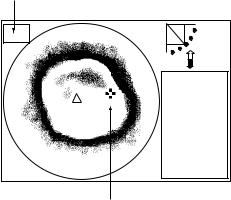
Typical horizontal mode display
With the tilt angle lowered, your ship is at the center of the screen. The bottom, which appears in reddish-brown color, is displayed as a circle and fish echoes appear within the circle.
2-2
2. HORIZONTAL MODE
2.3Choosing the Range
The [RANGE] control chooses the detection (display) range. Choose the range according to either the fish species being searched or the depth desired. 15 ranges are available.
SEA SURFACE
Range indicated
on the screen.
BOTTOM
How to choose the range
Default horizontal mode range settings
Range No. |
Meters |
Feet |
|
|
|
1 |
10 |
40 |
2 |
20 |
80 |
3 |
40 |
120 |
4 |
60 |
200 |
5 |
80 |
300 |
6 |
100 |
400 |
7 |
120 |
500 |
8 |
160 |
600 |
9 |
200 |
700 |
10 |
250 |
800 |
11 |
300 |
1000 |
12 |
400 |
1200 |
13 |
500 |
1500 |
14 |
600 |
2000 |
15 |
800 |
2500 |
Normally, the range is set so that the bottom is traced at the lower part of the screen (like an echo sounder). Each time the [RANGE] control is operated the newly chosen range briefly appears in large characters at the screen top. Range is always displayed at the top right-hand corner of the screen.
Note 1: Unit of range measurement may be chosen from among meters, feet, fathoms, passi/braza and Hiro (Japanese), with UNIT on the SYSTEM SETTING 1 menu. For further details, see UNIT in paragraph 5.4.2.
Note 2: Ranges may be freely preset as desired. For further details, see paragraph 5.4.4.
2-3
2. HORIZONTAL MODE
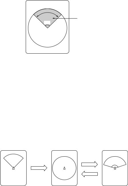
2.4Choosing Sector Width
Sector means the width of the transducer training. The [SECTOR] control chooses the training (display) area among the sixteen positions shown in the table below. Clockwise rotation of the control increases the sector width; counterclockwise rotation decreases it.
96° |
Display sector |
(shown: 96°) |
Display sector
|
1 |
2 |
3 |
4 |
5 |
6 |
7 |
8 |
9 |
10 |
11 |
12 |
13 |
14 |
15 |
16 |
Sector |
|
|
|
|
|
|
|
|
|
|
|
|
|
|
|
|
width |
6 |
24 |
48 |
72 |
96 |
120 |
144 |
168 |
192 |
216 |
240 |
264 |
288 |
312 |
336 |
360 |
(°) |
|
|
|
|
|
|
|
|
|
|
|
|
|
|
|
|
In the full-circle mode (360°) the direction of training is clockwise; in the half-circle mode the direction is clockwise to counterclockwise alternately.
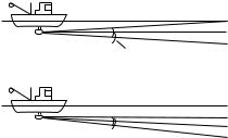
One-touch selection of 360° sector
Each pressing of the [FULL/HALF] key alternately chooses 360° sector (full circle) or 168° sector (half circle). If the [SECTOR] control is operated following the selection of the full-circle display, the next pressing of the [FULL/HALF] key presents the full-circle display.
Sector set with |
Full circle |
Half circle |
SECTOR control |
||
|
FULL/HALF |
FULL/HALF |
|
key |
|
|
key |
168° |
How the FULL/HALF key works
2-4
2. HORIZONTAL MODE
2.5Choosing Train Center
The [TRAIN] control chooses the center direction of the detection range. The range of adjustment is 0° to 354° in increments of 6°. The chosen bearing is shown with a filled circle, the train indicator, on the bearing scale.
0° (360°) → 6° → 12° → 18° → ... 354°
Train indicator
Sector
Train center
2-5

2. HORIZONTAL MODE
2.6Choosing the Tilt Angle
2.6.1Choosing the tilt angle
The tilt angle shows the direction to which the sound wave is emitted. When the sound wave is emitted horizontally, the tilt angle is said to be 0° and when emitted vertically, 90°. To set a tilt angle, operate the [TILT] control. Watch the tilt angle indication and the tilt angle indicator at the top right corner of the screen. The tilt angle can be set in increments of 1°, from +5° (upward) to 90° (downward). Automatic tilt selection is also available. See AUTO TILT on page 2-24 for details.
Choose the tilt angle depending on target fish. For surface fish choose a small angle (about 5°) to minimize sea surface reflections and for bottom fish, a large angle (about 40°) to search a wide area.
Soundome
+5°
0° Horizontal direction
Transducer |
Tilt angle setting range |
90° Vertical direction
Sounding beam and tilt angle
2-6
2. HORIZONTAL MODE
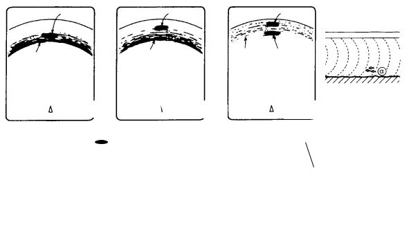
2.6.2Relation between tilt angle and echo
Refer to the illustration below to see the relation between tilt angle and bottom echo.
Case 1: Tilt angle 30° to 40°: This tilt angle will display the entire bottom since it is captured by the full width of the beam.
Case 2: Tilt angle 10° to 20°: This tilt angle will only display half the bottom since it is only captured by the lower half of the beam.
Case 3: Tilt angle 0° to 5°: This tilt angle may or may not capture the bottom since the returning echo is weak.
The figure below illustrates how two fish schools “a” and “b” are displayed on the screen using three different tilt angles.
Case 1(Tilt angle 30° to 40°): Case 2(Tilt angle 10° to 20°): Case 3(Tilt angle 0° to 5°):
Fish school is obscured by the bottom.
Fish school is located above the bottom (midwater). Fish school is located close to the bottom.
Case 1 |
Case 2 |
|
Case 3 |
|
|
|
|
|
|
|
|
Fish school "a" |
Fish school "a" |
Fish school "a" |
Bottom |
Bottom |
Bottom |
||||||
|
|
|
||||||
|
|
|
Fish school "b" |
|||||
|
|
|
|
|
|
|||
|
|
Case 1 |
|
|
Case 2 |
|
|
Case 3 |
|
|
|||||||
|
|
|
|
|
||||
|
|
|
|
|
|
|
|
|
|
|
|
|
|
|
|
|
|
Fish echo and tilt angle
2-7
2. HORIZONTAL MODE
Points to consider
•Normally, a vertically distributed fish school is a better sonar target than the bottom, because it reflects the transmitted pulse back toward the transducer.
•In case 3, both fish schools “a” and “b” are presented. Generally speaking, however, midwater fish schools tend to be larger than bottom fish schools and they are often displayed near the bottom on the display.
•It is difficult to detect bottom fish when they are not distributed vertically.
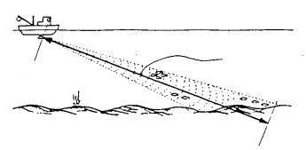
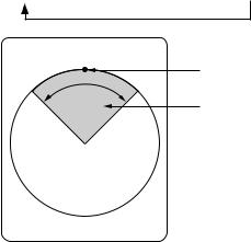
2.6.3Tilt angle for surface fish
Sound emitted from the sonar transducer forms an oval-shaped beam with a width of approximately 8° in the vertical direction (vertical beam width). The tilt angle is indicated by the angle between the center line of the beam and the horizontal plane. Then, if the tilt angle is set to 0°, the center line is parallel with the sea surface and one half of the emitted sound goes upward, toward the sea surface.
This causes one half of the emitted sound to be reflected toward the transducer and displayed on the screen as sea surface reflections. When the sea is calm, since the sound is reflected just like a light hitting a mirror at a narrow incident angle, it propagates away and the sea surface reflections become negligible.
However if the sea is not calm enough, they will become dominant and interfere with observation of wanted echoes. To minimize these sea surface reflections and to search fish schools effectively, the tilt angle is usually set between 5° and 6° so the upper portion of the beam becomes almost parallel with the sea surface. When the sea is rough, the tilt angle is slightly increased to lessen the affect of sea surface reflections.
Sea surface
Tilt angle 0° |
8° |
Sea surface
Tilt angle 5-7°  8°
8°
Tilt angle
2-8
2. HORIZONTAL MODE
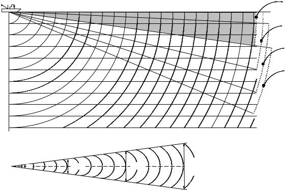
2.6.4Suitable tilt angle
The figure below illustrates the relationship among tilt angle, depth and detection range. Refer to it to find out the suitable tilt angle for a given depth/detection range.
Tilt angle and beam coverage (frequency 180 kHz, vertical beamwidth 8° at -3 dB)
|
|
|
400 |
Range (m) |
100 |
200 |
300 |
0° |
|
(200) |
(400) |
(600) |
(800) |
|
20(40) |
|
|
|
5° |
|
|
|
|
|
40(80) |
|
|
|
|
60(120) |
|
|
|
10° |
|
|
|
|
|
80(160) |
|
|
|
|
100(200) |
|
|
|
15° |
(m) Depth
200(400)
Vertical width of sonar beam |
|
300 m |
|
200 m |
|
||
|
|
|
|
|
100 m |
|
|
8° |
14 m |
28 m |
42 m |
Tilt angle and beam coverage
2-9
2. HORIZONTAL MODE
2.7Choosing the Training Speed
The training speed determines how fast the transducer scans the sounding sector. Two choices are available, normal speed and high speed, and one may be chosen with the [FAST SCAN] key. Each time the key is pressed, “NORM” (normal speed) or “FAST” (high speed) momentarily appears at the screen top.
Normal (6°): 60 transmissions required to complete the full 360° picture. High (12°): 30 transmissions required to complete the full 360° picture.
The time required to train a full circle depends on range used and other factors. The table below shows the time required to complete one full circle on each range.
Range |
|
1 |
2 |
3 |
4 |
5 |
6 |
7 |
8 |
9 |
10 |
11 |
12 |
13 |
14 |
15 |
|
Unit |
ft |
40 |
80 |
120 |
200 |
300 |
400 |
500 |
600 |
700 |
800 |
1000 |
1200 |
1500 |
2000 |
2500 |
|
Time |
Norm |
11 |
11 |
11 |
11 |
11 |
11 |
13 |
15 |
17 |
20 |
25 |
30 |
37 |
49 |
61 |
|
required |
|||||||||||||||||
|
|
|
|
|
|
|
|
|
|
|
|
|
|
|
|
||
(sec) for |
|
|
|
|
|
|
|
|
|
|
|
|
|
|
|
|
|
|
|
|
|
|
|
|
|
|
|
|
|
|
|
|
|
||
one full |
Fast |
11 |
11 |
11 |
11 |
11 |
11 |
12 |
14 |
15 |
16 |
19 |
21 |
25 |
31 |
37 |
|
circle |
|
|
|
|
|
|
|
|
|
|
|
|
|
|
|
|
|
Unit |
m |
10 |
20 |
40 |
60 |
80 |
100 |
120 |
160 |
200 |
250 |
300 |
400 |
500 |
600 |
800 |
|
Time |
Norm |
11 |
11 |
11 |
11 |
11 |
11 |
11 |
14 |
17 |
21 |
25 |
33 |
41 |
49 |
65 |
|
required |
|||||||||||||||||
|
|
|
|
|
|
|
|
|
|
|
|
|
|
|
|
||
(sec) for |
|
|
|
|
|
|
|
|
|
|
|
|
|
|
|
|
|
|
|
|
|
|
|
|
|
|
|
|
|
|
|
|
|
||
one full |
Fast |
11 |
11 |
11 |
11 |
11 |
11 |
11 |
13 |
14 |
16 |
18 |
22 |
26 |
30 |
38 |
|
circle |
|
|
|
|
|
|
|
|
|
|
|
|
|
|
|
|
Note 1: The above values are for reference purposes. The actual training speed may vary. Note 2: The range setting must be at least 160 meters to activate high-speed training.
2.8Finding Echo Position with the Cursor
The cursor measures horizontal range, depth and bearing. Operate the Omnipad to place the cursor where desired. Cursor position data appears at the top left-hand corner on the screen.
Cursor position data
®: Horizontal range ¯: Depth
B: Bearing
NAV
DATA
Cursor
Location of cursor position data
2-10
 Loading...