

Page 1
TECHNICAL
MANUAL
PILOT A2, CE2
RS232 Events log
TECHNICAL MANUAL
From serial n° 17730124 till ...
Page 2

Revision table
TM Pilot A2 CE2 RS 232 Events Log_en : ref NT 1734
Date Revision Chapter Description
03/04/03 0 All index "a" Creation
08/01/07 1 index "b" New EMC standard, spare parts up date
Page 3

1 Overview ........................................................................................................... 7
1.1 General....................................................................................................7
1.2 Overview diagram ................................................................................. 8
1.3 Precautions to be taken before use...................................................... 9
1.4 Internal safety features.......................................................................... 9
1.5 Technical characteristics ......................................................................9
1.5.1 Electrical specifications .............................................................................................. 9
1.5.2 Electronic specifications............................................................................................. 9
1.5.3 Mechanical specifications .......................................................................................... 9
1.5.4 Conformity and norms.............................................................................................. 10
2 Description and operation............................................................................. 11
2.1 Physical description ............................................................................ 11
2.1.1 The display board and the front panel...................................................................... 12
2.1.2 CPU board ............................................................................................................... 14
2.1.3 The power supply board and the battery.................................................................. 17
2.1.4 Mechanical gear box unit ......................................................................................... 20
2.1.5 Mechanical plunger unit ........................................................................................... 20
2.2 Functional description.........................................................................21
2.2.1 Syringe control and maintenance assembly ............................................................ 21
2.2.2 Motorisation assembly ............................................................................................. 21
2.2.3 External connection sub-assembly .......................................................................... 21
3 Description of the menus .............................................................................. 23
3.1 Configuration menu of the current operation parameters ............... 23
3.1.1 Menu access............................................................................................................ 24
3.1.2
3.1.3
3.1.4
3.1.5
3.1.6
3.1.7
3.1.8
3.1.9
3.1.10
3.1.11
3.1.12
3.1.13
3.1.14
3.1.15
3.1.16
3.1.17 Typical syringe/details correspondence table .......................................................... 33
PAr1, configuration of the memorisation type ...................................................... 25
PAr2, configuration of the syringe selection type................................................. 25
PAr3,
configuration of the maximum flow rate that may be selected on the keyboard ...... 26
PAr4, configuration of the list of syringes that may be selected........................... 26
PAr5, configuration of the compulsory priming .................................................... 27
PAr7, configuration of the KVO flow rate ............................................................. 27
PAr9, configuration of the RS232 communication speed..................................... 28
PArA, configuration of the empty syringe mode ................................................... 28
PArb, configuration of the frequency of preventive checks .................................. 29
PArC, configuration of the drug display mode ...................................................... 29
PArd, configuration of the Flanges detection mode ............................................. 30
PArF, configuration of the bolus flow memorisation mode................................... 30
PArG, configuration of the drugs list ..................................................................... 31
PArJ, configuration of the mains disconnection signal......................................... 32
PAr0, configuration of the date and time.............................................................. 32
PiloteCE2_A2_RS232horodaté_enTDM.fm 3
Page 4

3.2 Calibration menu.................................................................................. 35
3.3 Service test menu ................................................................................ 37
4 Preventive maintenance.................................................................................39
4.1 Recommendations............................................................................... 39
4.2 Maintenance schedule......................................................................... 39
4.2.1 Preventive maintenance........................................................................................... 39
4.2.2 Quality control .......................................................................................................... 39
4.3 Checks .................................................................................................. 41
4.3.1 Test access.............................................................................................................. 41
4.3.2 Visual check ............................................................................................................. 41
4.3.3 Running time and last servicing inspection date ...................................................... 42
4.3.4 Indicator lights check................................................................................................ 42
4.3.5 Keyboard check ....................................................................................................... 43
4.3.6 Checking the battery voltage.................................................................................... 44
4.3.7 Display of the last 10 alarms .................................................................................... 44
4.3.8 Total operation time check ....................................................................................... 46
4.3.9 TTL serial link test .................................................................................................... 46
4.3.10 RS 232 serial link check ........................................................................................... 47
4.3.11 Checking the software version. ................................................................................ 47
4.3.12 Checking the ADC.................................................................................................... 48
4.3.13 Checking the position sensor ................................................................................... 48
4.3.14 Buzzer test ...............................................................................................................49
4.3.15 Display of the calibration values............................................................................... 49
4.3.16 Checking the syringe clamp ..................................................................................... 49
4.3.17 Checking the syringe group number ........................................................................ 50
4.3.18 Checking the list of syringes .................................................................................... 50
4.3.19 Checking the disengagement................................................................................... 50
4.3.20 Checking the flanges detection system.................................................................... 50
4.3.21 Checking the syringe head detection system........................................................... 51
4.3.22 Checking backpressure............................................................................................ 52
4.3.23 Checking the pre-alarm and end of infusion alarm .................................................. 52
4.3.24 Checking the linearity............................................................................................... 53
4.3.25 Checking mains/battery operation............................................................................ 53
4.3.26 Battery autonomy test .............................................................................................. 54
4.3.27 Continuity test .......................................................................................................... 54
4.3.28 Quality Control Certificate ........................................................................................ 55
4.4 Flow rate control.................................................................................. 57
4.4.1 Measurement with a computer ................................................................................. 57
4.4.2 Measurement with scales......................................................................................... 59
4.4.3 Measurement using a test tube ................................................................................ 61
4.5 Cleaning and disinfecting ................................................................... 63
4.6 Storage.................................................................................................. 64
44 PiloteCE2_A2_RS232horodaté_enTDM.fm
Page 5

5 Diagnostic ....................................................................................................... 65
5.1 Troubleshooting guide ....................................................................... 65
5.2 Error messages ....................................................................................67
6 Operation sheets ............................................................................................ 71
N°1, Procedure: Display and central unit boards .................................... 73
N°2, Procedure: Syringe clamp ................................................................. 75
N°3, Procedure: Syringe detection system .............................................. 77
N°4, Procedure: Motor + Opto + Disk........................................................ 83
N°5, Procedure: Dynamometer sensor ..................................................... 85
N°6, Procedure: Plunger advance control potentiometer ....................... 91
N°7, Procedure:
Plunger cover and/or disengagement lever + anti-siphon arm......93
N°8, Procedure: Power supply board........................................................ 95
N°9, Procedure: Battery door and battery ................................................97
N°10, Procedure: Plug holder wired.......................................................... 99
N°11, Procedure: Ribbon cable winding kit............................................ 101
N°12, Procedure: Syringe head detection plunger kit ...........................105
N°13, Procedure: Centering ring kit ........................................................ 109
N°14, Procedure: Flex circuit and tube kit .............................................. 113
N°15, Procedure: Upper and lower cases ............................................... 119
7 Calibration..................................................................................................... 123
7.1 Calibration procedure........................................................................ 123
7.1.1 Calibration access.................................................................................................. 123
7.1.2
7.1.3
EtA.4 Calibration of the 3 battery voltage levels................................................ 124
EtA.6 Calibration of the position sensor. ........................................................... 124
8 Spare parts catalogue.................................................................................. 125
8.1 Upper case..........................................................................................125
8.2 Lower case.......................................................................................... 127
8.3 Plunger unit ........................................................................................ 129
8.4 Mechanical Gear box .........................................................................133
8.5 Labels..................................................................................................135
PiloteCE2_A2_RS232horodaté_enTDM.fm 5
Page 6

66 PiloteCE2_A2_RS232horodaté_enTDM.fm
Page 7

1 Overview
1.1 General
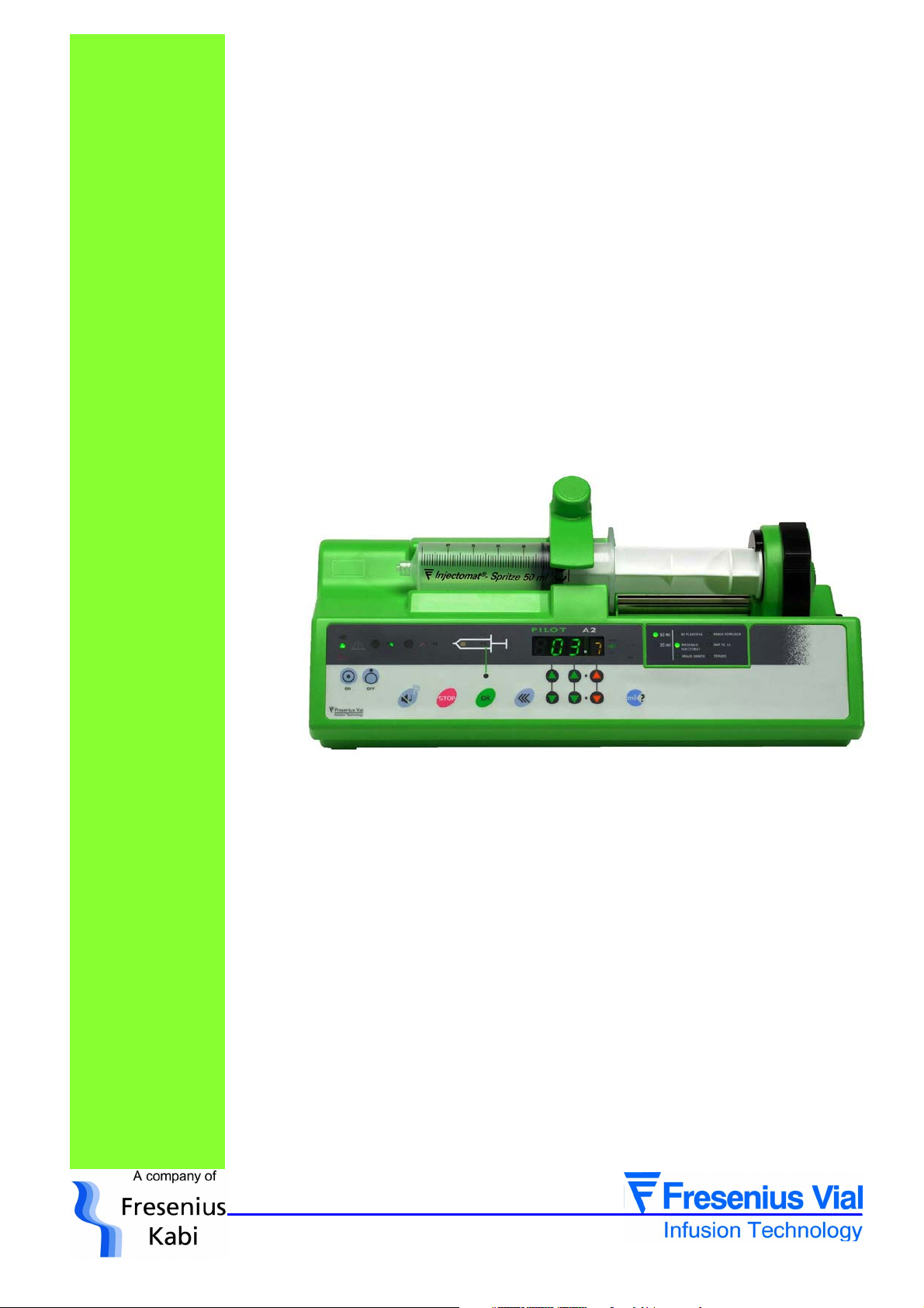
The Pilot A2 RS 232 Events log is a syringe pump intended for the infusion of intravenous
agents at a accurate, low flow rate. The wide choice of syringes, the use of the universally
recognised control symbols and the synoptic display of the alarms contribute to making the
Pilot A2 RS 232 Events log easy to use. The adjustable occlusion detection, the correct
positioning detection and the overall syringe protection system guarantee optimum safety.
Its technical characteristics, the flow range from 0.1 to 400 ml/hr (configured at
200 ml/hr) and its excellent accuracy (+
Pilot A2 RS 232 Events log, the ideal instrument for medical services.
The Pilot A2 RS 232 Events log is equipped with a 16ko-EEPROM enabling the
memorization of 896 events. These events are available for consultation through the ISCTRL
maintenance software, 4.1 and upper version.
1% on the device) contribute to making the
01_011b_en.fm 7
Overview
Page 8

Ext
12/15 V
15 W
1.2 Overview diagram
230 V
EPROM
128K x 8
UART
RAM
8K x8
Interface
bus
Power supply
Battery
EEPROM
512
BUS
SPI
ON / OFF
CPU
DC-DC
converter
Watch
dog
Opto
interface
ADC
Motor
driver
Step by
step
motor
Motor speed
sensor
Syringue body
sensor
Antisiphon
sensor
Displacement
transducer
Nurse call
(option)
Occlusion
switch
Disengagement
switch
LCD
display
Flanges switch
LED
display
RS 232
Keyboard
Master
Buzzer
LCD
driver
LED
driver
Overview
8 01_011b_en.fm
Page 9

1.3 Precautions to be taken before use
The symbol in the concise instrument instructions guide of the device recommends that
the operator’s guide should be read complelety in accordance with standard EN 60601-1.
Fresenius Vial may in no case be held responsible for medical problems or any other
problems resulting from inadequate use of the equipment.
Refer to the User’s instructions for further details.
!
1.4 Internal safety features
As soon as it is switched ON, the device activates a continuous function inspection system.
Any internal failure or any problem related to the operating procedure in progress is detected
immediately. Nevertheless, abnormal operation of the equipment with no obvious cause must
always be reported to the qualified technicians in your establishment or our After Sales
service.
In case of single fault condition, an alarm is activated for any flow rate deviation of ± 5% in
comparison with the normal flow rate.
A second check activates an alarm in the event of deviation of 1 ml in comparison with the
anticipated infused volume, or if a flow rate deviation of ± 20% is identified. The alarm is
triggered by the most rapidly detected deviation.
The Pilot A2 Events log is fitted with an internal battery to continue operation in the event of
a power cut. Furthermore, a safety fuse protects the mains from further disturbance.
1.5 Technical characteristics
1.5.1 Electrical specifications
! Power supply: 230 V - 50-60 Hz.
! Max. consumption : 23 VAC.
! Fuse F2: 100 mAT 250 V IEC 127.
! Battery: 6 V - 1,1 / 1,3 Ah.
! External power supply: 12 - 15 V DC -15 W.
1.5.2 Electronic specifications
The Pilot syringe pump is fitted with 3 circuit boards:
! Motor power supply and control board.
! CPU board.
! Keyboard display board.
1.5.3 Mechanical specifications
! Overall dimensions H x W x D: 120 x 330 x 155 mm.
! Weight: approximately 2,2 kg.
01_011b_en.fm 9
Overview
Page 10
1.5.4 Conformity and norms
0459
Safety of Electro
Medical
Equipements
EMC
(ElectroMagnetic
Compatibility)
Conform to the 93/42/CE Medical Directive. IP34 Protection against
splashing liquid.
Conform to EN/IEC 60601-1 and EN/IEC 60601-2-24 Protection against
leakage current: CF type.
Conform to EN/IEC 60601-1-2 (first edition) and EN/IEC
60601-2-24
Since 2001,electromagnetic compatibility standards have evolued.
Pilot A2 RS 232 Events log that serial number is higher than 18908961 with EN/IEC
60601-1-2 (second édition) and EN/IEC 60601-2-24 complies standards.
Detailed information concerning electromagnetic compatibility is available in the chapter
"Guidance and manufactureris declaration on EMC" of the User Manual.
Protection against electric
shocks: class II.
Overview
10 01_011b_en.fm
Page 11
2 Description and operation
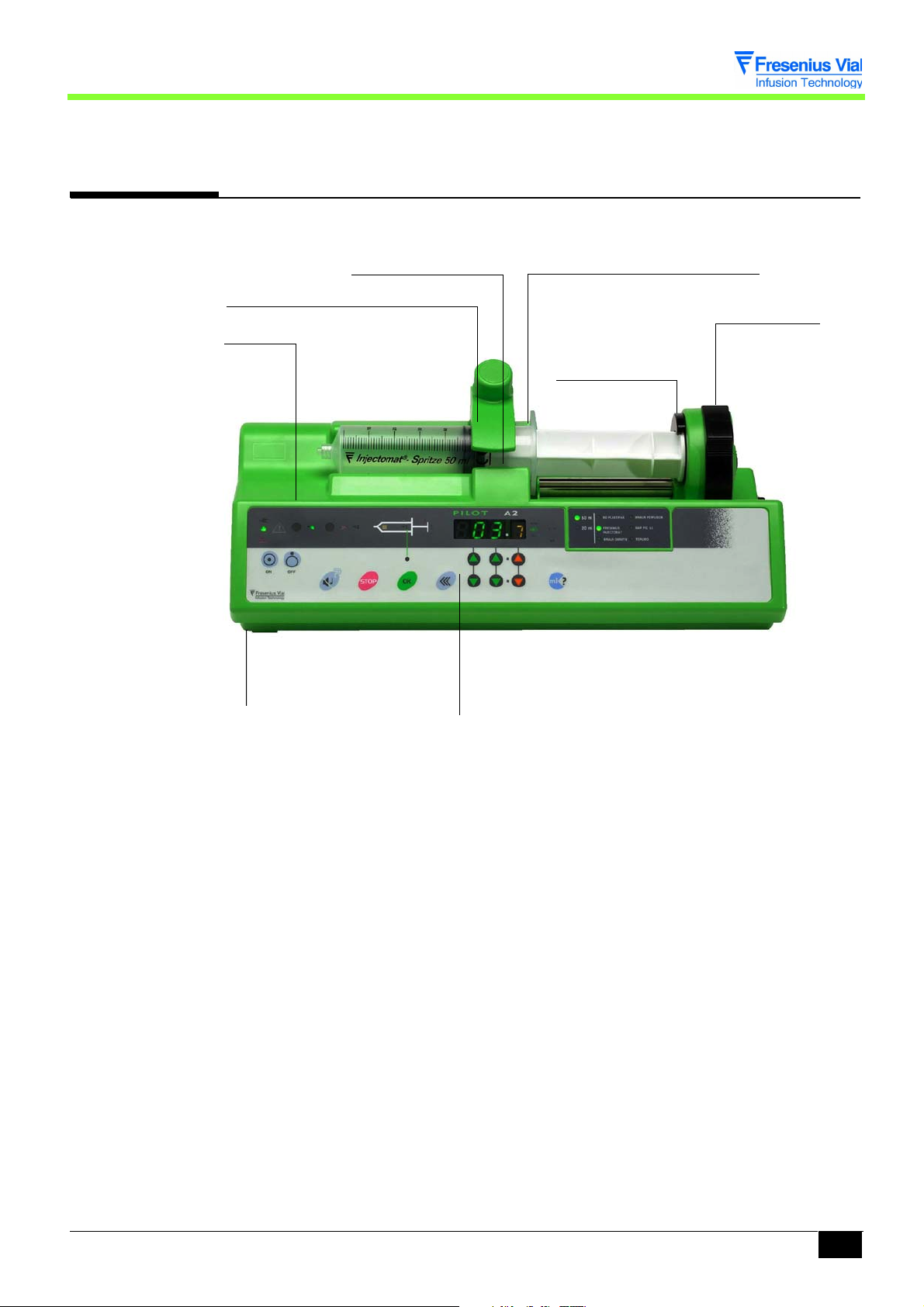
2.1 Physical description
Syringe clamp
Upper case
Lower case
Flanges switch
Flanges positioning groove
Plunger disengagement
control
Anti-siphon arm
Front control panel
The Pilot A2 Events log is fitted with an upper case and a lower case.
! The upper case holds the syringe clamp and contains:
" A display board associated with the front control panel.
" A CPU board.
! The lower case contains:
" A power supply board and a battery.
" A mechanical base unit.
" A plunger unit.
Description and operation
02_008b_en.fm 11
Page 12
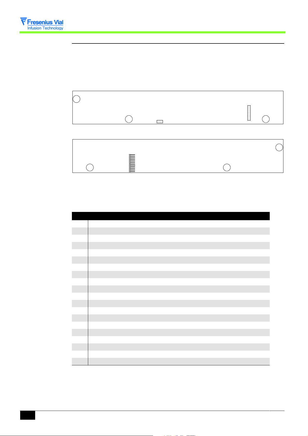
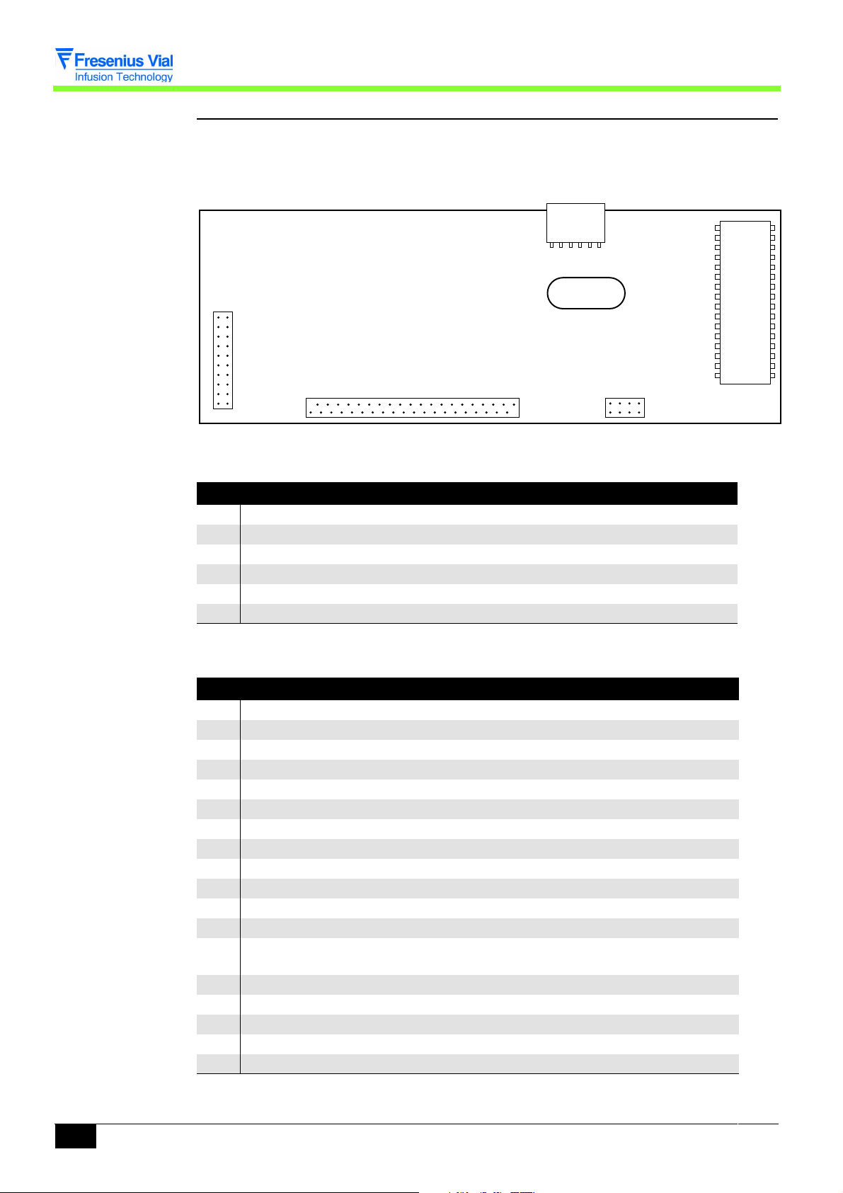
2.1.1 The display board and the front panel
The display board is mounted under the front control panel and is fitted with all the organs
required for man-machine interaction.
! Keyboard interface.
! Control lamps and overview diagrams.
! 7-segment display units.
J1
J3
Solder side display board.
J2
Component side display board.
This board is connected to the different parts of equipment by means of connectors.
J1 connector to CPU board
Pin Description
1 SEG1 display matrix Line 1
2 SEG2 display matrix Line 2
3 SEG3 display matrix Line 3
4 SEG4 display matrix Line 4
5 SEG5 display matrix Line 5
6 SEG6 display matrix Line 6
7 SEG7 display matrix Line 7
8 SEG8 display matrix Line 8
9 COL1 display matrix Column 1
10 COL2 display matrix Column 2
11 COL3 display matrix Column 3
12 FAIL LED control Fail
13 COL/DIG 9 LED type control "
14 LIG1 keyboard interface Line 1
15 LIG2 keyboard interface Line 2
16 LIG3 keyboard interface Line 3
17 LDSECT lighting control Mains LED
18 +5V power supply
19 VBAT power supply
20 GND power supply
Description and operation
12 02_008b_en.fm
Page 13

J2 connector to keyboard
Pin Description
1 Column 1
2 Column 2
3 Column 3
4 Column 4
5 Column 5
6 Column 6
7 Line 1
8 Line 2
9 Line 3
10 To n
11 Toff
12 Gnd power supply
J3 connector to CPU board
Pin Description
1Ton ON key
2 Tof f O F F k ey
3 SI SPI bus
4 Clk SPI bus
5 CSLCD SPI bus
6 Buzz BUZZER control
7 Vbat power supply
8 Gnd power supply
02_008b_en.fm 13
Description and operation
Page 14
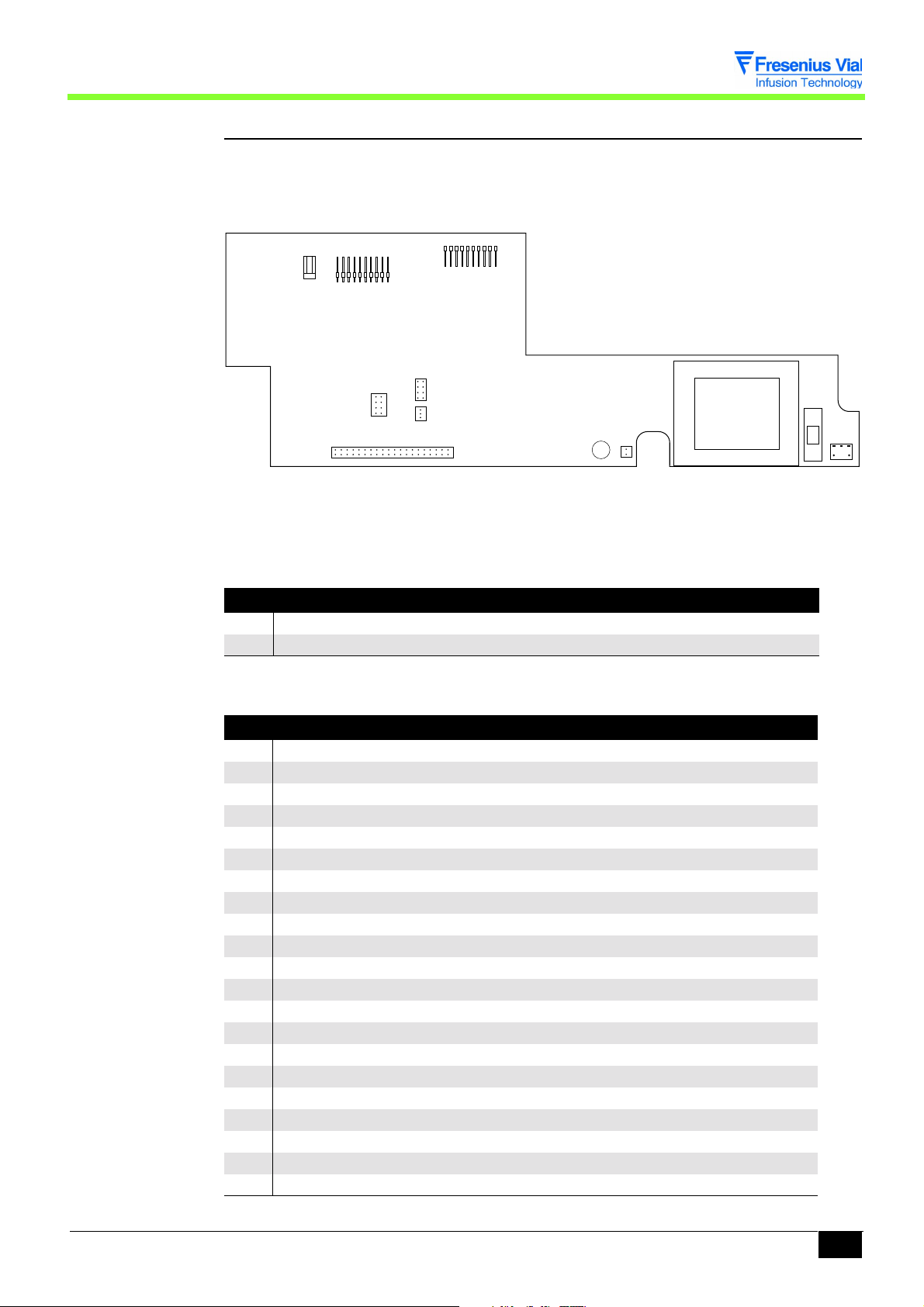
2.1.2 CPU board
The CPU board holds an 80C32 microprocessor. It is mounted and connected to the display
board through J4 and J5 connectors.
A ribbon cable connects this to a power supply board by means of a connector J3.
J2
J4
J3
CPU board
J2 connector: to flanges detection switch and syringe detection opto-electronic sensor
Pin Description
1 Ground
2 Flanges contact
3 Opto anode diode +5V
4 Common points between cathode LED , opto 1 and opto 2 transistor emitters.
5 Opto 1 transistor collector
6 Opto 2 transistor collector
J3 connector to power supply board
Pin Description
1+5V
2 Gnd
3+Vbat
4 Gnd
5 Phase A Motor control
6 Phase B Motor control
7 Phase C Motor control
8 Phase D Motor control
9 I signal Motor control
10 Boost signal Motor control
11 Sopt1 Opto rotation motor output
12 Sopt2 Opto anti-siphon
13 Apinf Nurse call independent of the buzzer
signal
14 Cdopt1 Opto rotation motor control output
15 Cdopt2 Opto anti-siphon module control
16 Off Signal off key pressed
17 Sect Mains power supply on signal
18 Cdalim Power cut signal
Description and operation
J5
14 02_008b_en.fm
Page 15

J3 connector to power supply board
Pin Description
19 Ldsect Mains LED control
20 Cts Clear to send
21 Deb/off Disengagement signal
22 Rts request to send Request to send
23 Occ/off Occlusion signal
24 Buz Nurse call relay control
25 Eoc End Of adc conversion
26 Csadc Selection spi adc bus
27 Clk Clock spi adc bus
28 Si Data in spi adc bus
29 So Data out spi adc bus
30 Cdana Analogue sensor power supply control
31 Rx2 Receive data TTL
32 Tx2 Transmit data TTL
33 Txd1 Transmit data TTL
34 Rxd1 Receive data TTL
35 Ton ON key
36 Tof f OFF key
37 +Vbat Power supply
38 Gnd
39 +5V
40 Gnd
J4 connector to display board
Pin Description
1 Seg1 display matrix Line 1
2 Seg2 display matrix Line 2
3 Seg3 display matrix Line 3
4 Seg4 display matrix Line 4
5 Seg5 display matrix Line 5
6 Seg6 display matrix Line 6
7 Seg7 display matrix Line 7
8 Seg8 display matrix Line 8
9 Col1 display matrix and keyboard Column 1
10 Col2 display matrix and keyboard Column 2
11 Col3 display matrix and keyboard Column 3
12 Fail diode fail control
13 Rdcrt current reduction control
14 Lig1 keyboard interface Line 1
15 Lig2 keyboard interface Line 2
16 Lig3 keyboard interface Line 3
17 Ldsect mains LED control
18 +5V power supply
19 Vbat power supply
20 Gnd power supply
02_008b_en.fm 15
Description and operation
Page 16

J5 connector to display board
Pin Description
1Ton ON key
2 Tof f OF F key
3Si spi bus
4 Clk spi bus
5 Cslcd spi bus
6 Buzz buzzer control
7 Vbat power supply
8 Gnd power supply
Description and operation
16 02_008b_en.fm
Page 17
2.1.3 The power supply board and the battery
The power supply board is mounted on the lower case. It allows to supply the electronic parts
using the network 230 V AC or the external 12 / 15 DC. It also charges the 1.1 or 1.3 Ah
battery.
J6
J7
J8
J5
J9
J3
J4 J1
J2 F1
Power supply board.
This board is connected to the different parts of equipment by means of connectors.
J1 connector to mains
Pin Description
1 Neutral
2 Phase
J2 connector to CPU board
Pin Description
1 +5V controlled power supply
2 Gnd power supply
3 +Vbat power supply
4 Gnd power supply
5 Phase A Motor control
6 Phase B Motor control
7 Phase C Motor control
8 Phase D Motor control
9 I signal Motor control
10 BOOST signal
11 Sopt1 Opto rotation module output
12 Sopt2 Opto anti-siphon module output
13 N.U
14 Cdopt1 Opto rotation module control
15 Cdopt2 Opto anti-siphon module control
16 Off Off key pressed on the ON/OFF button
17 SECT Mains supply presence signal
18 CDALIM Power cut signal
19 LDSECT Mains LED control
20 CTS Clear to send
21 DEB/OFF Disengagement signal active at 0
F2
Description and operation
02_008b_en.fm 17
Page 18

J2 connector to CPU board
Pin Description
22 RTS Request to send
23 OCC/OFF Occlusion signal active at 0
24 BUZ Nurse call relay control
25 EOC End of ADC conversion
26 CSADC Selection bus SPI ADC
27 CLK Clock bus SPI ADC
28 SI Data IN bus SPI ADC
29 SO Data out bus SPI ADC
30 CDANA Analogue sensor power supply control
31 RX2 receive data TTL
32 TX2 transmit data TTL
33 TXD1 transmit data TTL
34 RXD1 receive data TTL
35 Toff OFF key
36 Ton ON key
37 +Vbat Power supply
38 Gnd
39 +5V
40 Gnd
J3 connector to potentiometer
Pin Description
1Vref
2 Centre point
3Gnd
J4 connector to internal battery
Pin Description
1 + battery
2 - battery
J5 connector to motor
Pin Description
1+Vbay
2 +Vbat
3 Phase D
4 Phase C
5 Phase B
6 Phase A
7 Opto rotation anode diode /+5V
8 Opto rotation cathode diode
9 Opto rotation transistor collector
10 GND/ opto rotation transistor emitter
Description and operation
18 02_008b_en.fm
Page 19

J6 connector to RS232 and Master plugs
Pin Description
1TX1
2 +5V
3RX1
4 Gnd
5 Interface validation
6 Nurse call relay common point
7 Nurse call relay normally open
8 Nurse call relay normally closed
9 CD ON external on
10 CD OFF external off
11 I-OPTON Motor control output
12 I-SECT Mains led
13 +Vbat External power supply plug
14 RX2
15 TX2
16 Gnd
17 CTS
18 RTS
19 BUZ
20 NC
J7 connector to external DC power supply
Pin Description
1 ± external power supply
2 ± external power supply
J8 connector to disengagement micro-switch, force sensor and anti-siphon switch
Pin Description
1 Not used
2 Micro-switch input/output
3 Micro-switch input/output
4 Not used
5 Opto anti-siphon cathode diode
6 Opto anti-siphon anode diode/+5V
7 Opto anti-siphon transistor collector
8 Disengagement micro-switch on
9 Disengagement micro-switch off
10 Gnd
Do not forget to dismount the ribbon cable holder on the power supply board before
extracting the mechanical assembly from the housing (risk of breaking the ribbon
cable).
02_008b_en.fm 19
Description and operation
Page 20

J9 connector, test points
Pin Description
1GND
2 Position sensor output
3 Battery discharge control output
4 Amplified force sensor output
5 Cd coupler power supply 0-5V
6 Motor control opto output
7 Force and position sensor reference voltage
8 Piston head detection opto output
9 Control/APIN F
10 Control/APIN F
2.1.4 Mechanical gear box unit
The mechanical base unit is composed of a motor-reducer block driving a screw-and-nut unit.
At the shaft end, the motor receives a control panel associated with an opto-electronic switch.
The mechanical base unit also accommodates a potentiometer fitted with a rack pinion
system.
2.1.5 Mechanical plunger unit
The mechanical plunger unit is mounted onto the mechanical gear box. The gear box ensures
the displacement movement of the plunger through a screw / nut system.
The plunger is fitted with a disengagement control allowing to separate this from the screwand-nut system.
Description and operation
20 02_008b_en.fm
Page 21

2.2 Functional description
From a functional point of view, the Pilot A2 Events Log is composed of three subassemblies:
! A syringe position control and maintenance assembly.
! A motorisation assembly.
! An external connection assembly.
2.2.1 Syringe control and maintenance assembly
The syringe if fitted into the upper case and held in position by means of a syringe clamp.
Detection of the syringe size (60 cc or 20 cc) is carried out by two opto-electronic sensors
mounted onto the syringe clamp.
The flanges switch ensures the syringe flanges are correctly positioned in the groove.
Associated with an opto-electronic sensor, the anti-siphon arm controls the piston position.
Composed of a micro-switch fitted to the plunger, an anti-occlusion system triggers an alarm
whenever force on the piston is excessive.
2.2.2 Motorisation assembly
This sub-assembly moves the piston in the syringe.
It is put into motion by means of a motor-reducer unit associated with a screw-and-nut
system.
A motor rotation disk mounted on the shaft end of the motor and associated with an opto-
electronic sensor controls the rotation.
A potentiometer controls the plunger movement by means of a rack pinion system.
A micro-switch allows for control of the disengagement device.
2.2.3 External connection sub-assembly
The Pilot A2 Events log has three connectors located at the rear end of the lower case:
! A 12-15 V DC, 15 W type external power supply connector.
! An RS 232 connector.
02_008b_en.fm 21
Description and operation
Page 22

Description and operation
22 02_008b_en.fm
Page 23

3 Description of the menus
3.1 Configuration menu of the current operation parameters
The configuration menu enables users to adapt the Pilot to the specific needs of each
department. It provides access to the menus allowing for customisation of the parameters
associated with current operation modes.
Fresenius Vial recommends users to implement the selected configuration procedures in the
presence of a member of its qualified personnel or a member of the technical department.
It is possible to exit the configuration mode at any time by pressing the
This menu enables users to:
PAr1: select the type of flow rate memorisation.
!
!
PAr2: select the syringe selection mode.
!
PAr3: modify the maximum flow rates which can be selected using the keyboard.
!
PAr4: configure the list of syringes that can be selected.
!
PAr5: select the compulsory priming.
!
PAr7: select the KVO flow rate.
PAr9: select the RS232 communication speed.
!
!
PArA: select the empty syringe mode.
!
PArb: select the frequency of preventive checks.
!
PArC: select the drug display mode.
!
PArd: choose whether or not to activate the flanges detection mode.
!
PArF: select the Bolus memorisation mode.
!
PArG: enter the list of drugs.
!
PArJ: choose whether or not to activate the mains disconnection signal.
!
PAr0: enter the current date and time.
OFF key.
03.2_008b_en.fm 23
Description of the menus
Page 24
3.1.1 Menu access
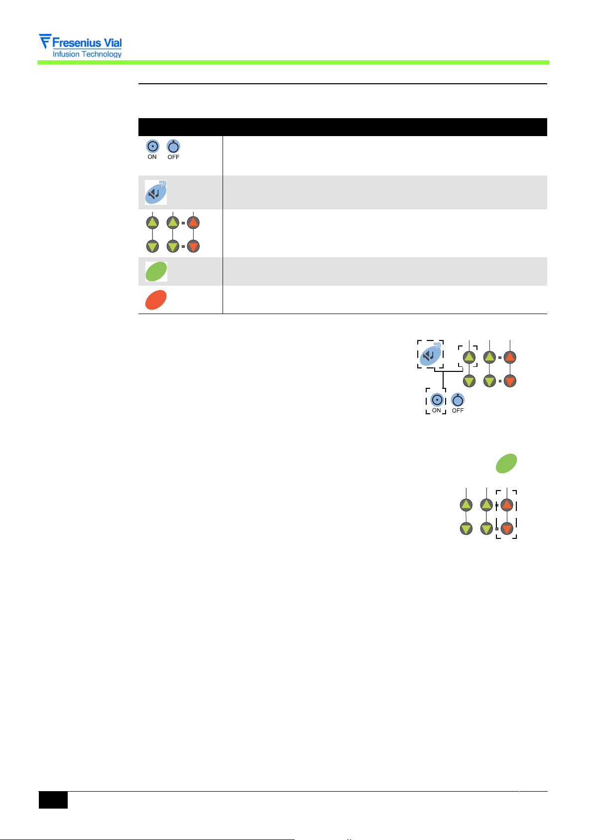
OP
Useful keys
Key Function
ON, is used to switch the machine ON.
OFF, is used to switch the machine off when pressed for over three
seconds.
SILENCE ALARM, is used to access the configuration mode of the
current operation parameters.
The selection keys allow to scroll the figures and letters on the tenths,
units, tens segments etc.
OK
STSTOP
CONFIRM, is used to validate a choice.
STOP, is used to cancel the current configuration.
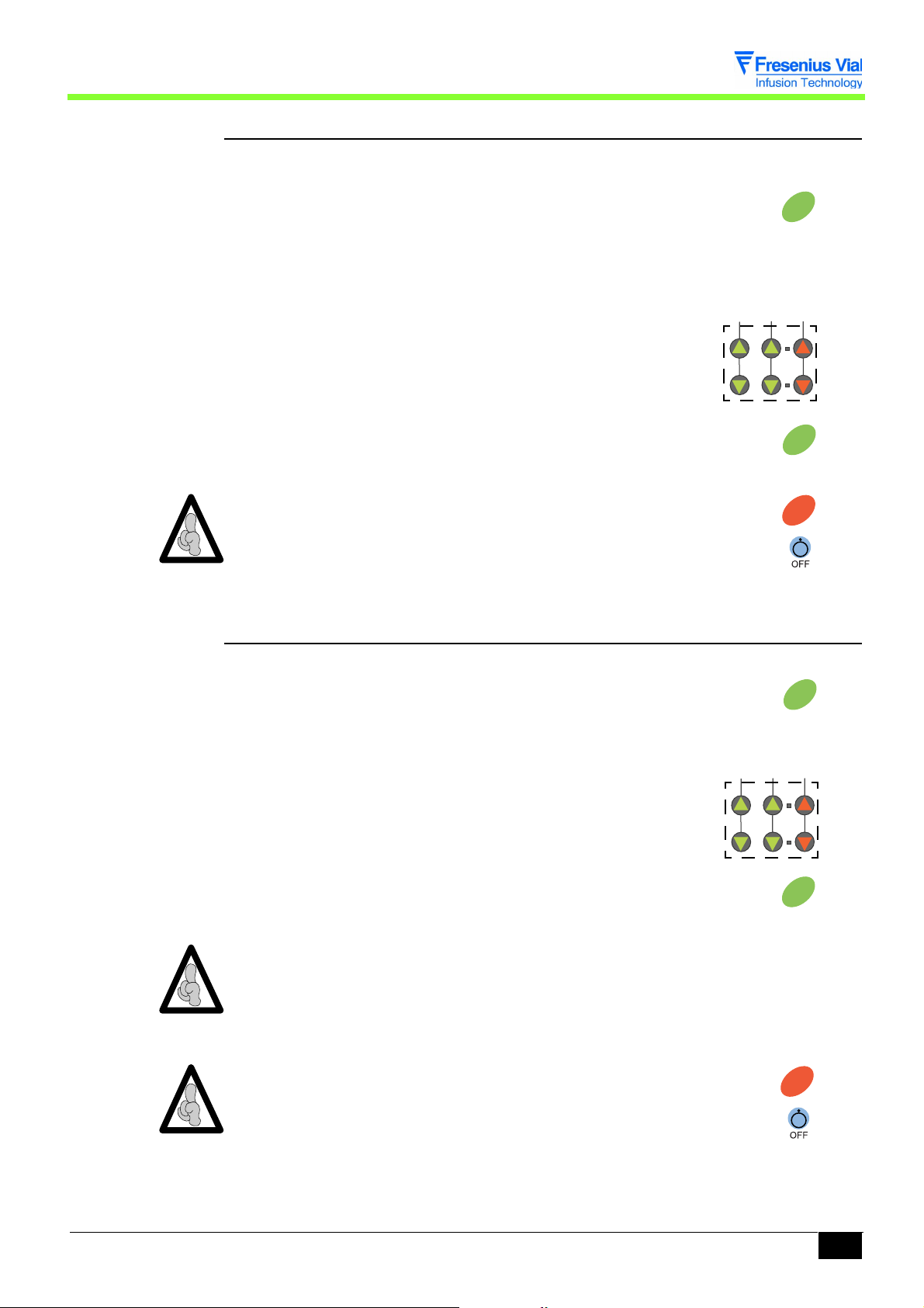
Switch to configuration mode.
! Press "SILENCE ALARM" and "TENS" simultaneously.
! Maintain this position while pressing "ON".
! When
PAr is shown on the display unit, release the
selection of "SILENCE ALARM" and "TENS"
then validate within three seconds by pressing "CONFIRM".
!
PAr1 is shown by default.
! Switching from
PAr1 to PArO is carried out
using the "tenths" keys.
OK
Description of the menus
24 03.2_008b_en.fm
Page 25
3.1.2 PAr1, configuration of the memorisation type
OP
OP
This configuration enables users to choose whether or not to memorise the infusion flow rate
when the Pilot is shut down.
!
PAr1, press "CONFIRM"
" If MEM, the flow rate is memorised when the Pilot is
shut down, this value will be displayed by default when the
machine is next switched on.
" If noME, the flow rate is not memorised, the default
value is
00.0 each time the machine is switched on.
# Select the memorisation type using the selection
keys.
OK
" By validating once again, the type is memorised and it is
possible to select another configuration .
The modification may be cancelled by pressing the "STOP" key.
It is possible to exit the configuration mode at any time by pressing the
"OFF" key.
3.1.3 PAr2, configuration of the syringe selection type
This configuration enables users to choose the type of syringe selection.
!
PAr2, press "CONFIRM"
" If SEL3, automatic validation of the only syringe that
may be selected.
" If SEL4, when the Pilot is switched on, the user should
select the type of syringe installed.
# Choose the selection type using the selection keys.
OK
STSTOP
OK
" By validating once again, the type is memorised and it is
possible to select another configuration .
When mode
SEL3 is selected, and if there is a choice of more than one syringe, the
OK
Pilot automatically moves onto the configuration of the list of syringes that may be
selected
The modification may be cancelled by pressing the "STOP" key.
PAr4 when the machine is next switched on.
STSTOP
It is possible to exit the configuration mode at any time by pressing the
"OFF" key.
Description of the menus
03.2_008b_en.fm 25
Page 26
3.1.4 PAr3, configuration of the maximum flow rate that may be selec-
OP
ted on the keyboard
This configuration enables users to choose the maximum flow rate that may be selected using
the keyboard for each type of syringe.
Syringe type Min. flow rate (ml/hr) Max. flow rate (ml/hr)
50/60 cc 0,1 400
20 cc 0,1 275
Par3, press "CONFIRM"
!
" Select the syringe type using the keys.
20c, 20 ml.
#
#
50c, 50 ml.
" Press "CONFIRM"
# Select the maximum flow rate using the keys.
" By validating once again, the maximum flow rate is
memorised and it is possible to select another
configuration .
The modification may be cancelled by pressing the "STOP" key.
It is possible to exit the configuration mode at any time by pressing the
"OFF" key.
OK
OK
OK
STSTOP
3.1.5 PAr4, configuration of the list of syringes that may be selected
This configuration enables users to choose whether or not it may be selected for each type of
active syringe.
!
PAr4, press "CONFIRM"
" The LED of the syringe to be configured flashes.
SEL, this type of syringe may be selected when
# If
the Pilot is switched on.
# If
noSE, this type of syringe may not be selected
when the Pilot is switched on.
" Make your choice using the keys.
! Press "CONFIRM" to memorise the modification.
" The LED of the configured syringe is:
# Lit up is it may be selected.
# Off if it may not be selected.
Description of the menus
OK
OK
26 03.2_008b_en.fm
Page 27
Details of the syringe are displayed
OP
OP
when the "tenths" keys are pressed (see chapter 3.1.17
"Typical syringe/details correspondence table").
The modification may be cancelled by pressing the "STOP" key.
STSTOP
It is possible to exit the configuration mode at any time by pressing the "OFF"
key.
3.1.6 PAr5, configuration of the compulsory priming
This configuration enables users to choose whether or not priming is compulsory after
selection of a syringe.
!
PAr5 is displayed.
" Press "CONFIRM"
PurG, compulsory priming, pressing "BOLUS"
# If
during start-up is compulsory to switch to selection of
the flow rate.
noPu, priming is not compulsory, the flow rate
# If
may be selected upon start-up straight after validation
of the syringe.
" Make your choice using the keys.
OK
" By validating once again, the configuration is memorised
and it is possible to select another configuration .
The modification may be cancelled by pressing the "STOP" key.
OK
STSTOP
It is possible to exit the configuration mode at any time by pressing the
"OFF" key.
3.1.7 PAr7, configuration of the KVO flow rate
This configuration enables users to choose whether or not to activate the switching to KVO
flow rate.
!
PAr7, press "CONFIRM"
" If KVO, KVO flow activated, the infusion continues at
1,0 ml/hr (or at the same flow rate if this is under 1,0 ml/hr)
when the volume infused reaches the limit volume.
" If noKV, no KVO flow, infusion stops with a limit volume
alarm when the infused volume reaches the limit volume.
" Make your choice using the keys.
OK
Description of the menus
03.2_008b_en.fm 27
Page 28
" By validating once again, the configuration is memorised
OP
OP
OP
and it is possible to select another configuration .
OK
The modification may be cancelled by pressing the "STOP" key.
STSTOP
It is possible to exit the configuration mode at any time by pressing the
"OFF" key.
3.1.8 PAr9, configuration of the RS232 communication speed
This configuration enables the user to select the communication speed of the RS232 link.
!
PAr9, press "CONFIRM"
" If 19K2, speed at 19200 Bauds.
" If 19K2, speed at 9600 Bauds.
" If 4800, speed at 4800 Bauds.
" Make your choice using the keys.
" By validating once again, the configuration is memorised
and it is possible to select another configuration .
OK
OK
The modification may be cancelled by pressing the "STOP" key.
STSTOP
It is possible to exit the configuration mode at any time by pressing the
"OFF" key.
3.1.9 PArA, configuration of the empty syringe mode
This configuration enables users to choose whether or not to activate using the empty syringe
mode.
!
PArA, press "CONFIRM"
" If SVId, empty syringe mode activated.
" If SVId, empty syringe mode deactivated.
" Make your choice using the keys.
" By validating once again, the configuration is memorised
and it is possible to select another configuration .
OK
OK
The modification may be cancelled by pressing the "STOP" key.
STSTOP
It is possible to exit the configuration mode at any time by pressing the
"OFF" key.
Description of the menus
28 03.2_008b_en.fm
Page 29
3.1.10 PArb, configuration of the frequency of preventive checks
OP
OP
This configuration enables users to select the maintenance frequency which lies between 1
and 9999 hours.
!
PArb, press "CONFIRM"
" The current value is displayed.
" Display the new frequency value using the keys.
" By validating once again, the new frequency is
memorised and it is possible to select another
configuration .
OK
OK
The modification may be cancelled by pressing the "STOP" key.
STSTOP
It is possible to exit the configuration mode at any time by pressing the "OFF"
key.
3.1.11 PArC, configuration of the drug display mode
This configuration enables users to choose whether or not to display the first four letters of the
name of the drug used.
!
PArC, press "CONFIRM"
" If drUG, display activated, after validation of the
syringe type, the operator should select the name of the
drug used out of the choice of 15 names.
" If nodr, display deactivated, the Pilot does not offer a
choice of drug names.
" Make your choice using the keys.
" By validating once again, the configuration is memorised
and it is possible to select another configuration .
OK
OK
If The modification may be cancelled by pressing the "STOP" key.
STSTOP
It is possible to exit the configuration mode at any time by pressing the "OFF"
key.
Description of the menus
03.2_008b_en.fm 29
Page 30
3.1.12 PArd, configuration of the Flanges detection mode
OP
This configuration enables users to choose whether or not to activate the syringe flanges
position check.
!
PArd, press "CONFIRM"
" If AiLE, detection activated, inappropriate positioning
of the flanges is signalled by means of an alarm.
" If noAL, no detection, the inappropriate positioning of
the flanges is not checked.
" Make your choice using the keys.
OK
" By validating once again, the configuration is memorised
and it is possible to select another configuration .
The modification may be cancelled by pressing the "STOP" key.
OK
STSTOP
It is possible to exit the configuration mode at any time by pressing the "OFF"
key.
3.1.13 PArF, configuration of the bolus flow memorisation mode
This configuration enables users to select the bolus flow memorisation mode.
!
PArF, press "CONFIRM"
" If MEM, bolus memorised, upon start-up of the Pilot, the
bolus flow given corresponds to the last selected.
" Si noME, bolus not memorised, upon start-up of the
Pilot, the bolus flow given is that defined by default.
" Make your choice using the keys.
OK
If the "not memorised" mode is selected, the bolus default value must be defined.
" If the noMEis selected, the 50 cc LED lights up and the
bolus flow is displayed.
# Using the keys, enter the bolus value to be defined by
default for a 50 cc syringe.
# Press "CONFIRM" to memorise it
OK
Description of the menus
30 03.2_008b_en.fm
Page 31

" The 20 cc LED lights up and the bolus flow is displayed.
OP
OP
# Using the keys, enter the bolus value to be defined by
default for a 20 cc syringe.
" By validating once again, the configuration is memorised
and it is possible to select another configuration .
The modification may be cancelled by pressing the "STOP" key.
OK
STSTOP
It is possible to exit the configuration mode at any time by pressing the
"OFF" key.
3.1.14 PArG, configuration of the drugs list
This configuration enables users to enter the list of drugs that may be used by the Pilot.
!
PArG, press "CONFIRM"
" The first four letters of the drug name are displayed.
# The first letter flashes.
# Modify the first letter using the "tens" or "units" keys.
" Press "CONFIRM" to memorise it and move onto the next
letter
" When the last letter is validated, the next drug is
displayed.
" To validate the one or several modification(s), the entire
list of drugs must be scrolled. When the last drug is
validated, the
PArG menu is displayed.
OK
OK
The modification may be cancelled by pressing the "STOP" key.
STSTOP
It is possible to exit the configuration mode at any time by pressing the "OFF"
key.
03.2_008b_en.fm 31
Description of the menus
Page 32

3.1.15 PArJ, configuration of the mains disconnection signal
OP
This configuration enables users to choose whether or not to activate the power cut detection
beep.
!
PArJ, press "CONFIRM"
" If SEC.t, detection activated, a power cut is signalled
by a beep.
" If noS;E, no detection.
" Make your choice using the keys.
OK
" By validating once again, the type is memorised and it is
possible to select another configuration .
The modification may be cancelled by pressing the "STOP" key.
It is possible to exit the configuration mode at any time by pressing the "OFF"
key.
3.1.16 PAr0, configuration of the date and time
This configuration enables to enter the current date and time.
!
Par0, press "CONFIRM"
" Date adjustment (d/M/Y)
d: day m: month y: year
" Make your choice using the keys.
" Press "CONFIRM"
" Time adjustment
OK
STSTOP
OK
OK
H : hour m: minute
" Make your choice using the keys.
" Press "CONFIRM".
It is possible to exit the configuration mode at any time by pressing the "OFF"
key.
Description of the menus
32 03.2_008b_en.fm
OK
Page 33

3.1.17 Typical syringe/details correspondence table
Brand Capacity (ml) Identification
BD Perfusion 50 BPf
BD Plastipak 50 BDk
BD Plastipak 20 BDk
Braun Omnifix 50 BrO
Braun Omnifix 20 BrO
Braun Perfusor 50 BrP
Braun Perfusor 20 BrP
Didactic Line France 50 DiL
Didactic Perfusion 50 DiP
Dispomed Spritze 50 Dis
Fresenius Injectomat 50 FrI
Fresenius P Spritze 50 FrP
Ivac 50 IVa
Map Gliss L L 50 MLL
Map Pic L L (Indolor) 50 MPL
Sherwood Monoject 50 SMJ
Sherwood Monoject 20 SMJ
Te ru m o 50 Tr m
Te ru m o 2 0 Tr m
Tutoject type T 50 TJT
03.2_008b_en.fm 33
Description of the menus
Page 34

Description of the menus
34 03.2_008b_en.fm
Page 35

Configuration, calibration and inspection
3.2 Calibration menu
The calibration menu is reserved for authorised personnel only.
To determine the operation mode of the different calibrations, refer to the
“Calibrations” chapter
This menu allows for calibration:
ETA4 : of the three levels of battery voltage alarms.
!
!
ETA6 : of the displacement potentiometer.
03.3_002a_en.fm 35
Configuration, calibration and inspection
Page 36

Configuration, calibration and inspection
36 03.3_002a_en.fm
Page 37

Configuration, calibration and inspection
3.3 Service test menu
The service test menu is reserved for authorised personnel only. It enables users to perform a
series of Pilot inspections to validate its efficient operation (see "Checks"chapter). This must
be carried out each time parts are replaced.
The Service tests may also be performed more easily and more quickly using a PC
with installed maintenance software (consult our After Sales Service).
The Service test menu enables users to perform a series of 16 tests or checks:
!
tSt1: Display of the running time and the maintenance date.
!
tSt2: Indicator lights test.
!
tSt3: Keyboard test.
!
tSt4: Display of the battery voltage.
!
tSt5: Display of the codes of the last 10 alarms.
!
tSt6: Display of the total running time.
!
tSt7: TTL serial link test.
!
tSt8: RS 232 serial link test.
!
tStA: Display of the software version.
!
tStb: Display of the analogue input.
!
tStC: Display of the plunger position.
!
tStd: Buzzer test.
!
tStE: Display of the calibration values.
!
tStf: Display of the syringe type.
!
tStG: Display of the syringe group.
!
tStH: Display of the list of syringes.
03.4_002a_en.fm 37
Configuration, calibration and inspection
Page 38

Configuration, calibration and inspection
38 03.4_002a_en.fm
Page 39

4 Preventive maintenance
4.1 Recommendations
The Pilot syringe pump can only be checked, serviced or repaired by Fresenius Vial or by a
certified and approved maintenance service. Any abnormal functioning of the pump must be
brought to the attention of your in-house qualified technical personnel or our After-Sales
Service.
Should you need to return the pump to our After-Sales Service, it should be cleaned,
disinfected and very carefully packaged, preferably in its original packaging, before being
sent.
For all information concerning the repair and use of the pump, kindly contact our After-Sales
Service or our Sales department.
Fresenius Vial is not liable for loss or damage to the pump during its transport to our AfterSales Service.
4.2 Maintenance schedule
4.2.1 Preventive maintenance
In order to maintain the pump’s performance, a Preventive Maintenance inspection
must be carried out every 3 years. This procedure, which includes changing the
battery, should be carried out by a qualified technician.
Any abnormal functioning or failure must be reported to the qualified technical staff in your
organisation or to our After-Sales Service. In these instances, the pump should not be used.
Important: If these maintenance procedures are not observed, the pump’s correct
operation will be impaired.
4.2.2 Quality control
At the request of the health organisation, a quality check will be carried out every 12
months.
A quality check (not included in the guarantee) consists of different inspection procedures as
defined in the pump’s Technical Manual. Only a qualified technician may perform the quality
check which must be performed using Fresenius-Vial software.
For more information, kindly contact our After-Sales Service.
At the end of the device life, return it to an organization competent in the
treatment of the electrical an electronic equipment waste. Remove the
battery from the device and return it to competent recycling organization.
04.1&2_001b_en.fm 39
Preventive maintenance
Page 40

Preventive maintenance
40 04.1&2_001b_en.fm
Page 41

OP
Preventive maintenance
4.3 Checks
A checking certificate is available at the end of this chapter.
To ensure the check procedure is carried out efficiently, recharge the battery
beforehand (16 hours).
4.3.1 Test access
Keyboard description.
Key Function
ON, to switch the machine ON.
OFF, to switch the machine off when pressed for over three seconds.
SILENCE ALARM, to access the test mode.
STSTOP
OK
Activate the Service test.
! Press "SILENCE ALARM" and "UNITS" keys
simultaneously.
! Maintain this position while pressing "ON".
! When
! By default, the equipment starts with test n°1
! By using the selection keys, scroll the different tests on the
tSt. is displayed on screen, release selection of
the "SILENCE ALARM" and "UNITS" keys, then validate
within three seconds by pressing the "CONFIRM" key.
display unit.
STOP, to cancel the test in progress.
CONFIRM, to validate a choice.
The selection keys allow to scroll the figures and letters on the tenths,
units, tens segments etc.
tSt.1
OK
4.3.2 Visual check
Check the general appearance of the case and labels, and check for any traces of shock.
Preventive maintenance
04.3_002b_en.fm 41
Page 42

4.3.3 Running time and last servicing inspection date
OP
OP
This test allows for
display of the Pilot
running time since
its last servicing
inspection. It also
allows for display
and modification of
the "last" servicing
inspection date.
When the servicing
inspection date is
modified, the
running time is
reset.
!
tSt.1, press the "CONFIRM" key.
" If xxx.H: number of hours of use, 999 hours max.
" If xxx.J: number of days of use, 999 days max.
" If xxx.M : number of months, 999 months max.
(average duration of one month considered as 30 days).
" If CtrL is displayed alternately, the result exceeds the
max. servicing frequency memorised (see "
PArb,
Configuration of the frequency of preventive checks"):
carry out preventive maintenance procedures.
# By keeping the "tenths" keys pressed down, the
number of times the equipment has been switched on
is displayed.
! Press "CONFIRM" again to display the date of the last
servicing inspection.
" xx.d, day of the servicing inspection date.
" Validate once again,
xx.m, month of the servicing inspection date.
#
" By validating once again,
#
xxx.x, year of the servicing inspection date.
OK
OK
This test checks
the efficiency of
the indicator
lamps, and the
display units front
panel.
Each time this information is read, the month, day and year of the
servicing inspection date may be modified by using the tens and
units keys. This date will be stored in the EEPROM and the running
time will be reset.
" By validating once again, a different test may be selected.
The test may be stopped at any time by pressing the "STOP" key, and a
different test may be selected.
4.3.4 Indicator lights check
!
tSt.2, press "CONFIRM".
" All LEDs and 7-segment display units are ON.
" By validating once again,
# The LEDs and display units are scrolled one by one
from left to right. (display of the LEDs, 7-segment
display unit by segment and then by sets of 8).
The text is OK if all indicator lamps are lit up.
OK
STSTOP
OK
The test may be stopped at any time by pressing the "STOP" key, and a
different test may be selected.
STSTOP
Preventive maintenance
42 04.3_002b_en.fm
Page 43

4.3.5 Keyboard check
This test allows to
check that all
keyboard keys
function correctly.
!
tSt.3, press "CONFIRM".
" The message CLAV is displayed.
" Keep each key pressed down, one by one,
# Check the name of the key displayed on the display
unit.
The name of each key is displayed as follows:
Display Selected key
SIA.L
StoP
VAL
boLu
S-..
S.-.
S..S_..
S._.
SILENCE ALARM
STOP
CONFIRM
BOLUS
+ tens
+ units
+ tenths
- tens
- units
S_..
VPEr
If two or more keys are pressed simultaneously, the display unit shows "Err"
and an audio alarm sounds "beep!beep!beep!" indicating an error.
The "OFF" key is not included in the keyboard check.
The test may be stopped at any time by pressing the "CONFIRM" key for
over 3 seconds, and a different test may be selected.
- tenths
VOLUME INFUSED
OK
04.3_002b_en.fm 43
Preventive maintenance
Page 44

4.3.6 Checking the battery voltage
OP
OP
This test enables
users to display the
battery voltage in
Volts and tenths of
a Volt.
This test enables
users to display the
last ten Pilot
alarms in the form
of codes.
!
tSt.4, press "CONFIRM".
" The voltage is displayed in Volts.
" By validating once again, a different test may be selected.
The test may be stopped at any time by pressing the "STOP" key, and a
different test may be selected.
4.3.7 Display of the last 10 alarms
!
tSt.5, press "CONFIRM".
" The most recent alarm code is displayed xxx.0.
" Press the keys to display the following codes from
xxx.1 to xxx.9.
OK
OK
STSTOP
OK
" By validating once again, a different test may be selected.
The test may be stopped at any time by pressing the "STOP" key, and a
different test may be selected.
Alarm codes description:
Alarm Description
A10 Battery alarm
A11 Syringe clamp alarm
A12 End of infusion alarm
A13 Limit volume alarm
A14 Disengagement alarm
A15 Piston head alarm
A16 Occlusion alarm
A17 Flanges alarm
OK
STSTOP
Preventive maintenance
44 04.3_002b_en.fm
Page 45

Error codes description
Error Description
10 Internal RAM anomaly
20 External RAM anomaly
30 Eprom anomaly
40
50 Adc anomaly
60 Syringues parameters anomaly
70 Motor frequency anomaly
80 Keyboard matrix (key press non functioning) fault
01 Rotation (absence top turn) error
E32 Error concerning segment advance control
E52 Error concerning advance during compensation for play.
E72 Error concerning advance over the whole length.
E82 Error concerning advance flow rate
E03 Error concerning communication
14 Period frequency anomaly
24 Rotation direction anomaly
34 Flow rate / motor period calculation anomaly
44 Incoherence quartz µC principal and µC secondary
55 µC secondary access fault
16 Date and time in µC secondary verification
56 Association condition output/step number
66 LCD Display time-out
18 Maximum infused volume reached
28 Language file incompatible
CFPC Anomaly duringthe self set
COM Communication error
CTRL Preventive maintenance request
Access (E2prom) Eeprom anomaly
Electromagnetic disturbance exeeding standards
! Errors 10, 20, 30 and 40 cannot be stored in the EEPROM.
! If the Pilot switches off normally, the
! If the Pilot switches off due to a malfunction, the
flashing
04.3_002b_en.fm 45
F.
OFF message is displayed.
Off message is displayed with a
Preventive maintenance
Page 46

4.3.8 Total operation time check
OP
OP
This test enables
users to display the
total running time
of the Pilot. It is
not possible to
modify this time
manually.
This test enables
users to check the
efficiency of the
TTL (80C32) serial
link.
!
tSt.6, press "CONFIRM".
" If xxx.H: number of hours of use, 999 hours max.
" If xxx.J: number of days of use, 999 days max.
" If xxx.M : number of months, 999 months max.
(average duration of one month considered as 30 days).
# By keeping the "tenths" keys pressed down, the
number of times the equipment has been switched on
is displayed.
" By validating once again, a different test may be selected.
The test may be stopped at any time by pressing the "STOP" key, and a
different test may be selected.
4.3.9 TTL serial link test
To perform this test, use plug on which lines Rx and Tx are short-circuited (2 and 3).
!
tSt7, press "CONFIRM".
" Lt is displayed at the start of the test.
# If
LtEr is displayed, the test is not successful,
otherwise, the test is successful.
OK
OK
STSTOP
OK
" By validating once again, a different test may be selected.
The test may be stopped at any time by pressing the "STOP" key, and a
different test may be selected.
OK
STSTOP
It is impossible to carry out this test when the PC is in communication with the Pilot. In this
case, "OPEN" is displayed.
Preventive maintenance
46 04.3_002b_en.fm
Page 47

4.3.10 RS 232 serial link check
OP
OP
This test enables
users to check the
efficiency of the
RS 232 (2691)
serial link.
To perform this test, use plug on which lines Rx and Tx, RTS and CTS are short-circuited
(2 and 3, 7 and 8).
!
tSt8, press "CONFIRM".
" NoUA is displayed if the UART is missing, in which
OK
case the test cannot be carried out.
" RTS andCTS line operation test.
# If the test is unsuccessful,
NoRC is displayed, in
which case the test cannot be continued.
" Lr is displayed.
LrEr is displayed, the test is not successful,
# If
otherwise, the test is successful.
" By validating once again, a different test may be selected.
The test may be stopped at any time by pressing the "STOP" key, and a
OK
STSTOP
different test may be selected.
It is impossible to carry out this test when the PC is in communication with the Pilot. In this
case, "OPEN" is displayed.
Run this test to
display the
software version
and revision
numbers.
4.3.11 Checking the software version.
!
tStA, press "CONFIRM".
" eg. V09.8 is displayed:
09, software version number.
#
#
.8, revision number
" Press the tenths keys to display the EPROM checksum,
8d6F.
e.g.
" Press the other keys to display the software version index
A.
e.g. .
" By validating once again, a different test may be selected.
The test may be stopped at any time by pressing the "STOP" key, and a
different test may be selected.
OK
OK
STSTOP
Preventive maintenance
04.3_002b_en.fm 47
Page 48

4.3.12 Checking the ADC
Run this test to
read the result of
the conversion of
the five analogue
inputs and three
test inputs of the
converter.
!
tSt.b, press "CONFIRM".
" The result displayed is the first of the five analogue inputs
(from 0 to 4), example
" The second type of result displayed corresponds to the
converter test according to the channel number,
318.0.
xxx.Lis the 0 test input, xxx.M is the mid-scale
test input, and
Use the selection keys to move from one input to another.
" By validating once again, a different test may be selected.
Input Name
0 Battery voltage
1 N.U.
2 Force sensor
3 N.U.
4 Potentiometer displacement
L Converter zero test, between 0000 and 0004 if correct
M Converter mid-scale test, between 01FB and 204 if correct
H Converter full-scale test, between 03B and 3FF if correct
xxx.H is the ADC full scale test input.
OK
OK
This test enables
users to display the
plunger position in
mm and 10
mm.
Preventive maintenance
ths
of a
4.3.13 Checking the position sensor
tSt.C, using spacers ref. T300940E and T300775G,
!
" Position the spacer ref. T300940E and press "CONFIRM".
# in high position the display unit shows
115.0 + 0,5 mm.
" Position the spacer ref. T300775G and press
"CONFIRM".
# in low position the display unit shows
20.0 + 0,5 mm.
" By validating once again, a different test may be selected.
If the value is out of limits, recalibrate the position sensor (see "EtA.6 Position sensor
calibration.").
OK
48 04.3_002b_en.fm
Page 49

4.3.14 Buzzer test
Run this test to
check that the
buzzer is working.
Run this test to
display the
calibration values
stored in the
EEPROM.
! tSt.d, press "CONFIRM".
" The buzzer sounds continuously and the bEEp
message is displayed.
" By validating once again, a different test may be selected.
4.3.15 Display of the calibration values
!
tSt.E, press "CONFIRM".
" bAT.1 is displayed alternately with its calibration
value.
# Press one of the tenth keys to display the number of
calibrations carried out for this value
" Press one of the unit or tenth keys to move onto another
value.
Display Name
bat.1
bat.2
Alarm and pre-alarm battery voltage 6.3 V
Pre-alarm battery voltage 5.9 V
OK
OK
This test displays
the type of syringe
fitted to the Pilot.
bat.3
HIG.H
Lou
0.G
SK.G
Alarm battery voltage 5.7 V
Displacement potentiometer with large 115.0 mm spacer
Displacement potentiometer with small 20.0 mm spacer
Force meter with 0 kg
Force meter with 5 kg
4.3.16 Checking the syringe clamp
! tSt.F, press "CONFIRM" key
Using a 50 cc and 20 cc capacity syringe or the T301521 spacer.
" Place the syringe clamp in the higher position.
The display unit shows
" Fit the 50 cc syringe. The display unit shows 50c.c
" Fit the 20 cc syringe. Thedisplay unit shows 20c.c
" Place the syringe clamp in the lower position.
The display unit shows
---.-
---.-
OK
Capacities which are non-existent or non-configured in the EEPROM are displayed in the
form of
" By validating once again, a different test may be selected.
04.3_002b_en.fm 49
---.-.
OK
Preventive maintenance
Page 50

4.3.17 Checking the syringe group number
OP
Run this test to
determine for
which list of
syringes the
instrument has
been configured.
This test enables
users to display the
list of syringes
programmed in the
Pilot.
!
tSt.G, press "CONFIRM".
" The syringe group number configured in EEPROM is
displayed, example
" By validating once again, a different test may be selected.
G01.
4.3.18 Checking the list of syringes
!
tSt.H, press "CONFIRM".
" The syringe capacity is displayed and the corresponding
Led lights up.
" Each time a key is pressed:
# The syringe details are displayed.
# The Led corresponding to the details lights up.
# The one or several Led(s) corresponding to the
capacities lights up.
" Press stop to select a different test.
OK
OK
OK
STSTOP
4.3.19 Checking the disengagement
To carry out this operation, exit the test mode and press "OFF".
! Press "ON".
" Lift the disengagement lever.
# Check for presence of the mechanical disengagement
alarm (red Led at the end of the syringe diagram).
" Fit the device with the 50 cc syringe, ensuring the flanges
and plunger are in position.
" Release the disengagement lever.
# Ensure there is no mechanical lever release alarm.
# Check plunger locking.
4.3.20 Checking the flanges detection system
To carry out this operation, exit the test mode and press "OFF".
! Press "ON".
" Fit the device with the 50 cc syringe, ensuring the flanges
and plunger are in position.
" Ensure the syringe is detected appropriately eg.
50c.c.
" Place the syringe in the device ensuring the flanges is out
of the groove.
" Fit the syringe clamp and plunger correctly.
" Make sure the light alarm flashes, locating the problems
on the syringe diagram.
Preventive maintenance
50 04.3_002b_en.fm
Page 51

4.3.21 Checking the syringe head detection system
This check must be carried out for every syringe provided with the instrument.
! Check the functionality.
" Free play, without end play or dismounting of this.
! Check for alarm presence with:
" Syringe head detection arm in the upper position.
" Syringe head detection arm in the lower position.
Ensure there is no alarm in presence of spacers or 20 cc and 50 cc syringes.
! Using spacers ref. T301518 and T301519.
" To carry out this operation, exit the test mode and press
"OFF",
" Press "ON".
" Fit the instrument with the spacer ref T301518 and lock it
into position using the syringe clamp.
# Place the syringe plunger against the spacer with the
syringe head detection arm on the spacer.
#
20c.c is displayed without triggering the alarm.
" Fit the instrument with the spacer ref T301519 and lock it
into position using the syringe clamp.
# Place the syringe plunger against the spacer with the
syringe head detection arm on the spacer.
#
50c.c is displayed without triggering the alarm.
! Using 20cc and 50cc syringes.
" To carry out this operation, exit the test mode and press
"OFF",
" Press "ON".
" Fit the instrument with the 20 cc syringe and lock it into
position using the syringe clamp.
# Place the syringe plunger against the syringe with the
syringe head detection arm on the syringe plunger.
#
20c.c is displayed without triggering the alarm.
" Fit the instrument with the 50 cc syringe and lock it into
position using the syringe clamp.
# Place the syringe plunger against the syringe with the
syringe head detection arm on the syringe plunger.
#
50c.c is displayed without triggering the alarm.
04.3_002b_en.fm 51
Preventive maintenance
Page 52

4.3.22 Checking backpressure
OP
To carry out this operation, exit the test mode and press "OFF",
! Press "ON".
" Fit the instrument with the 50 cc syringe and lock it into
position using the syringe clamp, ensuring the flanges and
plunger are correctly positioned.
" Place the manometer (or any other pressure
measurement device) at the syringe outlet.
" Select a 50 ml "B-D PLASTIPAK" syringe by pressing
"CONFIRM".
" Check the position of the backpressure adjustment
button.
" Select a maximum flow rate and initiate the infusion by
pressing the "CONFIRM" key.
# Ensure there is no acoustic and visual alarm
(backpressure Led off).
# Check that the infusion Leds are flashing.
# Ensure the alarm is triggered for a value of
0,7 bar +
" Stop the infusion cycle by pressing the "STOP
INFUSION" key.
" Repeat the test setting the backpressure level to the
minimum and maximum levels.
# Min. backpressure = 0,4 bar +
# Max. backpressure = 1.2 bar +
0,1 bar.
0,1 bar.
0.2 bar.
OK
OK
STSTOP
4.3.23 Checking the pre-alarm and end of infusion alarm
To carry out this operation, exit the test mode and press "OFF",
! Press "ON".
" Fit the device with the syringe, ensuring the flanges and
plunger are in position.
" Ensure the syringe is detected appropriately eg.
50c.c.
" Select a "B-D PLASTIPAK" syringe filled to 20 ml.
" Select a flow rate of 120 ml/h.
# For normal flow rates, the pre-alarm is activated 5
minutes before end of infusion.
# Flow rate example: > 50 ml/h, the pre-alarm is
activated when the remaining volume equals 10% of
the total syringe capacity.
# Ensure the end of infusion pre-alarm is present.
" Press the "SILENCE ALARM".
# The acoustic alarm is silenced and the visual
signal is maintained.
" Measure the "hard height" at "end of infusion".
# 18,5 <
x < 19,5.
Top view
Preventive maintenance
52 04.3_002b_en.fm
Page 53

For accurate checking of the "hard height", do not move the plunger when measuring.
OP
If the "hard height" reading is out of limits, recalibrate the position sensor (see "EtA.6
Position sensor calibration.").
4.3.24 Checking the linearity
To carry out this operation, exit the test mode and press "OFF",
! Equipment required: Chronometer, calliper square, BD
Plastipak 50 ml syringe.
! Press "ON".
" Fit the device with the "B-D PLASTIPAK" 50 ml syringe,
ensuring the flanges and plunger are in starting position.
" Measure the distance X1 in mm.
" Ensure the syringe is detected appropriately eg.
50c.c.
" Select a "B-D PLASTIPAK" syringe filled to 50 ml.
" Select a flow rate of 50 ml/h.
" Press "CONFIRM" to start infusion and simultaneously
start the chronometer
" At 50 minutes, stop the infusion by pressing "STOP" and
measure the distance X2.
" Ensure X = X1 - X2 lies between
74,96 mm <
X < 76,47 mm.
Top view
OK
STSTOP
For accurate checking of the linearity do not move the plunger when measuring.
4.3.25 Checking mains/battery operation
To carry out this operation, exit the test mode and press "OFF",
! Connect the device to a mains supply and press "ON".
" Check the operation of the mains presence Led (indicator
in the shape of a plug).
! Disconnect the device from the mains.
" Check the mains power LED is "OFF" and the battery
LED is "ON".
Preventive maintenance
04.3_002b_en.fm 53
Page 54

4.3.26 Battery autonomy test
! Recharge the battery for 16 hours.
! Disconnect the device from the mains power.
" Fit the unit with 50 CC syringe then validate..
" Select a flow rate of 120ml/h then validate..
! Check the battery autonomy is higher than 1 hour.
4.3.27 Continuity test
Using a multimeter.
To carry out this operation, exit the test mode and press "OFF",
! Connect the multimeter to an ohmmeter.
" Check the electrical resistance shown by the ohmmeter is
over 10 MΩ :
# between phase and metal tube.
# between neutral and metal tube.
OK
OK
Preventive maintenance
54 04.3_002b_en.fm
Page 55

Preventive maintenance
4.3.28 Quality Control Certificate
Use this table to note the results of the different tests.
These tests can be done with dedicated Pilot software.
Equipment type: Code: Equipment series N°:
N° Procedure Resulting value
1 ! Check the general condition of the case and its labels.
2
3
4
5
6
7
8
! Display total running time,
(in hours, days or months):***************************************** ..........................
! Display the last servicing inspection date,
(in days, months or years):***************************************** ..........................
! Check all indicator lights,
! Check the keyboard,
! Display the total running time, tSt6
(in hours, days or months):***************************************** ..........................
! Check the position sensor,
" High position with T300940 spacer, check that the displayed
value is
" Low position with T300775 spacer, check that the displayed
value is
! Check the syringe clamp, tStF:
" Syringe clamp in high position, check that the displayed
value is
" Fit the device with a 50 cc syringe or a T301521 spacer, check that
the value displayed is
" Fit the device with a 20 cc syringe or a T301521 spacer, check that
the value displayed is
" Syringe clamp in low position, check that the displayed
value is
115.0 + 0.5 mm: ********************************** ..........................
20,0 + 0.5 mm: *********************************** ..........................
---.- :******************************************** ..........................
---.- :******************************************** ..........................
tSt1
tSt1
tSt2.
tSt3.
tStC:
50c.c :**************************** ..........................
20c.c :**************************** ..........................
Conformity
Yes No
9
10 ! Check the anti-siphon arm:
11 ! Check the backpressure (use a Fresenius Vial dynamometer):
! Check the list of programmed syringes, tStH.
" Free travel without end play.
" Presence of the alarm in high and low position.
" No alarm in presence of 20 cc and 50 cc syringe piston.
" Position of adjustment knob
0.6 < X bar < 0.8: ****************************************** ..........................
fiche_002b_en.fm 55
Preventive maintenance
Page 56

N° Procedure Resulting value
12 ! Check the linearity (60 cc BD Plastipack):
" Measure the plunger distance, X1 mm:************************ ..........................
" Measure the plunger distance after 50 mn pump running, X2 mm:..................
" Ensure 74,96 <
13 ! Check the presence end of infusion pre-alarm.
14 ! Check the end of infusion alarm:
" With a 60 cc BD, check that the hard height distance
is 18,5 <
15 ! Check the battery autonomy:
" Recharge the battery for 16 hours.
" Operate the Pilot for 1 hr at a flow rate of 120 ml/hr:********* ..........................
16 ! Carry out the electrical tests according to standard EN 60601-1
x mm < 19,5: ****************************************** ..........................
Name: Date: Signature:
X1-X2 mm < 76,47:*************************** ..........................
Conformity
Yes No
Comments:
Preventive maintenance
56 fiche_002b_en.fm
Page 57

Diagnosis
4.4 Flow rate control
4.4.1 Measurement with a computer
ISDébit software is required for measuring the flow with a computer. This software is the
property of Fresenius Vial. Please contact our After Sales Service for any further
information.
The operation mode defined by this software follows the standard EN-60-601-2-24 for
infusion pumps. It is up to the user to adapt this procedure to the software used.
In order to purchase the ISDébit flow rate control software, contact the Fresenius Vial
customer service.
The test procedure defined below must be carried out using a 50 ml or 20 ml syringe.
Equipment required
! Scales coupled to a microcomputer:
Flow rate value Scales sensitivity
5 ml/hr 1/10000th
x <
5 ml/hr < x < 30ml/hr 1/1000th
x > 30 ml/hr 1/100th
! Multi scales acquisition programme.
! Test tube or beaker with 1 ml graduating
! Liquid: distilled water and oil
! Luer lock type plastic syringe (50 or 20 ml).
! Catheter extension with Luer Lock (length 100 cm, inside diameter 2,5 mm).
! Needle:
Flow rate value Needle type
x <
30ml/hr G26
x > 30 ml/hr G18 or G21
Installation
! According to the installation drawings shown below.
1 cm
Cord
RS232
Anti vibration measurement table
Make sure the horizontal installation plane is respected.
04.4_001b_en.fm 57
Diagnosis
Page 58

! Fill the syringe with 50 ml of distilled water.
" Prime to eliminate any air bubbles.
! Secure the female Luer Lock end piece of the catheter
extension onto the syringe and the male Luer lock end piece
onto the needle.
! Fit the syringe onto the device.
! Fill the test tube ensuring the needle is dipped in the liquid
(> 1 cm).
" Add several drops of oil to create a greasy film on the
surface of the liquid. This way the user will avoid any
measurement error due to evaporation of the liquid.
! Place the test tube in the centre of the scales platform.
! Place the needle inside the test tube.
The infusion line (needle/catheter extension) must not rest on the scales/test tube
assembly.
! Press "ON" (device in mains supply mode).
" Prime the infusion line using the "BOLUS" key.
" Check that there are no air bubbles.
Operating mode
The software works following the operating mode described in the EN-60-601-2-24
standard for infusion pumps.
! Start the acquisition programme for the scales.
! Enter the necessary data to launch the programme without
validating the flow rate.
! Adjust the scales to the specified flow rate.
! Confirm the flow rate on the microcomputer so that the
automatic setting of the scales can take place.
! Start the infusion by pressing the "CONFIRM" key, when
00.00 appears on the scales display screen.
! When the specified time is over, note the error percentage
displayed on the screen.
OK
Diagnosis
58 04.4_001b_en.fm
Page 59

4.4.2 Measurement with scales
Equipment required
! Stop clock
! Scales
Flow rate value Scales sensitivity
5 ml/hr 1/10000th
x <
5 ml/hr < x < 30ml/hr 1/1000th
x > 30 ml/hr 1/100th
! Test tube or beaker with 1 ml graduating
! Liquid: distilled water and oil
! Luer lock type plastic syringe (50 or 20 ml)
! Catheter extension with Luer Lock (length 100 cm, inside diameter 2,5 mm).
! Needle:
Flow rate value Needle type
x < 30ml/hr G26
x > 30 ml/hr G18 or G21
Installation
! According to the installation drawings shown below.
1 cm
Anti vibration measurement table
Make sure the horizontal installation plane is respected.
! Fill the syringe with 50 ml of distilled water.
! Prime to eliminate any air bubbles.
! Secure the female Luer Lock end piece of the catheter
extension onto the syringe and the male Luer lock end piece
onto the needle.
! Fit the syringe onto the device.
! Fill the test tube ensuring the needle is dipped in the liquid
(> 1 cm).
! Add several drops of oil to create a greasy film on the
surface of the liquid. This way the user will avoid any
measurement error due to evaporation of the liquid.
! Place the test tube in the centre of the scales platform.
! Place the needle inside the test tube.
04.4_001b_en.fm 59
Diagnosis
Page 60

The infusion line (needle/catheter extension) must not rest on the scales/test tube
OP
assembly.
! Press "ON" (device in mains supply mode).
" Prime the infusion line using the "BOLUS" key.
" Check that there are no air bubbles.
Operating mode
! Select a flow rate.
For low flow rates (< 5 ml/hr), validate and wait for the infusion to stabilise for 1 hour. For
higher flow rates, wait for 10 to 30 minutes after infusion.
! Set the scales at
00.00 g.
! Start infusion by pressing the "CONFIRM" key, and start the
stop clock at the same time, (if necessary make a note of the
stop clock start value).
! Press the "STOP INFUSION" key to stop the test one hour
later.
! Note the value in grams of the “infused” liquid.
! Calculate the difference between the design value and the
real value.
1 gram = 1 ml.
! The error percentage can be calculated from this difference :
Real value Design value–()
--------------------------------------------------------------------------Design value
× Error percentage=
100
OK
STSTOP
Diagnosis
60 04.4_001b_en.fm
Page 61

4.4.3 Measurement using a test tube
Equipment required
! Stop clock.
! Test tube or beaker with 1 ml graduating
! Liquid: distilled water and oil
! Luer lock type plastic syringe (50 or 20 ml)
! Catheter extension with Luer Lock (length 100 cm, inside diameter 2,5 cm).
! Needle:
Flow rate value Needle type
x < 30ml/hr G26
x > 30 ml/hr G18 or G21
Installation
! According to the installation drawings shown below.
1 cm
Anti vibration measurement table
Make sure the horizontal installation plane is respected.
! Fill the syringe with 50 ml of distilled water.
" Prime to eliminate any air bubbles.
! Secure the female Luer Lock end piece of the catheter
extension onto the syringe and the male Luer lock end piece
onto the needle.
! Fit the syringe onto the device.
! Fill the test tube ensuring the needle is dipped in the liquid
(> 1 cm).
" Add several drops of oil to create a greasy film on the
surface of the liquid. This way the user will avoid any
measurement error due to evaporation of the liquid.
" Place the needle inside the test tube.
04.4_001b_en.fm 61
Diagnosis
Page 62

Operating mode
! Select a flow rate.
For low flow rates (< 5 ml/hr), validate and wait for the infusion to stabilise for 1 hour. For
higher flow rates, wait for 10 to 30 minutes after infusion.
! Start infusion by pressing the "CONFIRM" key, and start the
stop clock at the same time, (if necessary make a note of the
stop clock start value).
! Once the whole infused syringe is in the test tube, calculate
the difference between the design value and the real value:
Real flow rate = 50 ml/time in hours
! The error percentage can be calculated from this difference :
Real value Design value–()
--------------------------------------------------------------------------Design value
100
× Error percentage=
OK
Diagnosis
62 04.4_001b_en.fm
Page 63

Preventive maintenance
4.5 Cleaning and disinfecting
The pump form part of the patient's immediate environment. It is advisable to clean and
disinfect the device’s external surfaces of the device on a daily basis in order to protect
patient and staff.
! Disconnect the pump from its mains supply before cleaning.
! Do not place in an AUTOCLAVE nor IMMERSE the device, Do not let liquids enter the
device’s casing.
! If the device is placed in a high contamination risk unit, it is advisable to leave it in the room
during disinfecting, after having disinfected it with amoist cloth.
! Use a cloth soaked in DETERGENT-DISINFECTANT, previosly diluted with water if
required, to destroy micro organisms.
" Avoid abrasive scrubbing which could scratch the casing.
" Do not rinse or wipe the surfaces.
Do not use :
" ¨TRICHLOROETHYLENE-DICHLOROETHYLENE
" AMMONIA.
" AMMONIUM CHLORIDE
" CHLORINE AND AROMATIC HYDROCARBON.
" ETHYLENE DICHLORIDE-METHYLENE
" CHLORIDE-CETONE
These aggressive agents could damage the plastic parts and cause device malfunction.
Take car also with ALCOHOL based SPRAYS (20% -40% alcohol) .They lead to
tarnishing and small cracks in the plastic, and do not provide the neceeeary
cleaning prior to disinfection.
Disinfecting SPRAYS may be used, in accordance wih the manufacturer recommendation,
from a distance of 30 cm of the device, avoid the accumulation of the product in liquid form.
Avoid iodine-based solutions that may result in coloring some plastic parts permanently.
Please contact the appropriate service, responsible for cleaning and disinfecting products, in
your establishment for further details.
04.5&6_001b_en.fm 63
Preventive maintenance
Page 64

4.6 Storage
The device should be stored in a dry, cool place. In case of prolonged storage, the battery
should be disconnected via the battery access flap situated underneath the device.This
should be done by a qualified technician
! Storage conditions and carrying:
" Temperature: -10°C to 60°C / 14°F to 140°F.
" Atmospheric pressure: 500 hPa to 1060 hPa.
" Humidity: 10% to 90%, no condensation.
! Use conditions:
" Temperature: 5°C to 40°C / 41°F to 104°F.
" Atmospheric pressure: 700 hPa to 1060 hPa.
" Humidity: 20% to 90%, no condensation.
Fully recharge the battery before using the equipment to avoid any risks caused by micro
power cuts in the mains supply and to ensure maximum autonomy.
Preventive maintenance
64 04.5&6_001b_en.fm
Page 65

5 Diagnostic
5.1 Troubleshooting guide
Problems Causes Solutions
End of infusion detected too
early (at approximately 10 ml).
No end of infusion pre-alarm or
alarm.
! The installed syringe doesn’t
correspond with the syringe selected.
! Replace or validate the right
syringe brand.
! Recalibrate the position
sensor (Eta6) or with IS control
software.
Flow rate or displacement control
drift.
Occlusion alarm after the Pilot
has been turned on.
Occlusion alarm during the
infusion.
Disengagement alarm after the
Pilot has been turned on or
during the infusion.
Plunger head position alarm
unjustified.
! The installed syringe doesn’t
correspond with the syringe selected.
! The position sensor calibration values
have drifted.
! Wrong calibration of the force sensor.
! Force sensor out of order.
! Flexible circuit cut.
! The pressure limit selected is too low.
! Wrong calibration of the force sensor.
! Flexible circuit cut.
! The disengagement micro-switch is
defective.
! Flexible circuit cut.
! Optical switch and/or, anti-siphon
cam obturator are defective.
! Flexible circuit cut.
! Replace or validate the right
syringe brand.
! Check the position sensor
calibration values and recalibrate
it if necessary.
! Change the position sensor.
! Recalibrate and check the
force sensor.
! Replace the force sensor.
! Replace the flexible circuit.
! Select a highter pressure
limit.
! Recalibrate and check the
force sensor.
! Replace the flexible circuit.
! Replace the micro-switch.
! Replace the flexible circuit.
! Check the anti-siphon system
! Check the good condition of
the pusher cover internal
mechanism.
! Replace the flexible circuit.
Syringe clamp alarm injustified
Display defect: LED’s, 8
segments display units
The Pilot turns off when it is
disconnected from the mains
powers.
05.1_001b_en.fm 65
! Optical switchs and/or, syringe clamp
obturator are defective.
! Micro-switch and/or syringe flanges
detection conection are defective.
! Control transistors, LED’s and/or
display connection are defective
! Battery fuses is out of order.
! The battery is unplugged or the
battery cable is cut.
! Battery is totally discharged
! Check the syringe clamp and
replace the defective parts, if
necessary.
! Chek the good condition of
the display board.
! Replace the LED’s or the
control transistors.
! Check the display boad.
! Check the connectors which
link CPU and display boards.
! Replace the battery fuse.
! Check the battery connection.
! Replace the battery
Diagnostic
Page 66

Problems Causes Solutions
The power supply LED doesn’t
lit.
! Power supply fuse is out of order. ! Replace the power supply
fuse.
Battery alarm while it has been
completely charged.
Battery alarm while the Pilot is
connected to the mains power
supply.
The Pilot turns "ON" or turns
"OFF" alone.
! Voltage regulator MAX 652 is
defective (charging voltage greater than
10 V or lower than 5 V).
! Wrong calibration of the battery.
! Battery is totally discharged.
! The battery voltage calibration was
made while the Pilot was connected to
the mains power supply.
! Keyboard is defective.
! Power supply board is defective.
! Check the battery charge
voltage and replace the regulator
if necessary.
! Recalibrate the 3 battery
voltage levels with IS contol
software.
! Replace the battery.
! Recalibrate the 3 battery
voltage levels with IS contol
software.
! Recalibrate the 3 battery
voltage levels with a stabilisad
power supply adjusted at 9 volts
in order to set the device to
CFPC or ETAL modes.
! Replace the CPU board and
carry on a complete
configuration of the device.
! Check and replace the
keyboard if necessary.
! Check that there was no liquid
infiltration under the power
supply board relay.
! Check the relay and replace it
if necessary.
! Check the relay transistors
control and replace them if
necessary.
! Replace the power supply
board.
Some keys of the keyboard keys
don’t work.
After a fall
Diagnostic
66 05.1_001b_en.fm
! Keyboard is defective. ! Check the keyboard (test3)
Replace the keyboard if
necessary.
! Mechanical elements damaged ! Check that the centering ring,
the mechanical assembly and
the cases are intact.
Page 67

Diagnostic
5.2 Error messages
Error code Description Recommended action
Er10
Er20
Er30
Er40
Er50
Er60
Er70
! Internal RAM anomaly ! Reconfigure the Pilot with IS Control
software.
! Replace the CPU board and carry on a
complete configuration of the device.
! External RAM anomaly
! EPROM anomaly
! EEPROM anomaly
! ADC anomaly ! Check the ADC.
! Check the compatibility between the
power supply and the CPU Boards. See
PM0084.
! Replace the power supply board.
! Replace the CPU board and carry on a
complete configuration of the device.
! Syringes parmetters
anomaly
! Motor frequency anomaly
! Reconfigure the Pilot with IS Control
software.
! Replace the CPU board and carry on a
complete configuration of the device.
Er80
Er01
Keyboard anomaly
! Electromagntic
disturbance exceeding
standards limits
! Motor rotation error ! Check that there is no foreign body in
! Check and replace the keyboard if
necessary.
! Check that there is not liquid presence
inside the Pilot that could damage keyboard
and electronics booards.
! Replace the CPU board and carry on a
complete configuration of the device.
! Check the Pilot environment
the mechanical gear box.
! Check the good condition of the rotation
optical switch and the motor rotation disk.
! Check that the motor rotates when it
isn’t mounted on to the gear box.
! Replace the motor.
! Replace the gear box.
! Replace the power board.
05.2_001b_en.fm 67
Diagnostic
Page 68

Error code Description Recommended action
Er32
Er52
Er72
Er82
Er14
Er24
! Displacement error on a
short distance.
! Displacement error
during the compensation.
! Displacement error on
the whole lenght.
! Displacement error in
relation to the flow rate.
! Motor period calculation
anomaly
! Motor rotation direction
anomaly
! Check the position sensor attachement.
! Check the position sensor calibration.
! Check the ADC.
! Check the position sensor and replace if
necessary.
! Reconfigure the Pilot with IS Control
sofware.
! Reconfigure the Pilot with IS Control
software.
! Replace the CPU board and carry on a
complete configuration of the device.
! Check the motor rotation sensor.
! Replace the CPU board and carry on a
complete configuration of the device.
Er34
Er44
Er55
Er16
Er56
Er66
Er18
Er28
CFPC
! Flow rate / Motor period
calculation anomaly
! Quartz freqency anomaly ! Replace the quartz.
! Time clock access ! Replace power supply board.
! Time clock fault ! Check the time clock
! Software anomaly ! Reconfigure the Pilot with IS Control
! LCD time-out. ! Replace the display board.
! Maximum infused volume
reached.
! Imcompatible language
file.
! Anomaly during the selftest
! Reconfigure the Pilot with IS Control
software.
! Replace the CPU board and carry on a
complete configuration of the device.
! Replace power supply board.
! Replace the CPU board and carry on a
complete configuration of the device.
software.
! Restart the pilot.
! Reconfigure the Pilot with IS control
software.
! Reconfigure the Pilot with IS Control
software.
! Replace the CPU board and carry on a
complete configuration of the device.
COM
Diagnostic
68 05.2_001b_en.fm
! Comunication error ! Check the connection with the computer
Master.
Page 69

Error code Description Recommended action
CTRL
*: When the device is switched off and the EEPROM is rewritten, the checksum is rewritten
in the memory to save the settings.
If the hardware downtime is longer than the software downtime, the device is switched off
before the EEPROM is completely written: Non-conforming checksum.
Er(-)0 or CFPc: When the device goes into CFPc, you must reconfigure it: WATCH DOG
faulty.
! Preventive maintenance
request
! Perform the regular servicing checks
and update the maintenance date (test1)
! This error doesn’t jam the Pilot. Press
confirm to leave
05.2_001b_en.fm 69
Diagnostic
Page 70

Diagnostic
70 05.2_001b_en.fm
Page 71

6 Operation sheets
This chapter lists the set of dismounting/remounting sheets.
06.0_001a_en.fm 71
Operation sheets
Page 72

Operation sheets
72 06.0_001a_en.fm
Page 73

Operation sheets
N°1, Procedure: Display and central unit boards
Safety:
For safety reasons, the technician should not carry out any maintenance when the device is
connected to the 230 V mains supply voltage.
Disconnect the mains power supply cable.
Equipment required:
! 1 Posidriv Z1 screwdriver.
! 1 antistatic wriststrap.
Maintenance level:
Level 3, specialised technician (see documentation on biomedical training).
Procedure:
Access
! Turn the Pilot over onto the upper case.
! Unscrew the 6 Phillips head screws (ref. 1) located at the bottom of the lower case, which
link this to the upper case.
! Keep the Pilot assembled and turn it over onto the lower case.
! Remove the upper case making sure the CPU board flat jumper is not accidentally
removed in the process.
! Disconnect the CPU board flat jumper.
Hands must not come into contact with the CPU boards.
1
1
1
1
1
1
06.0_0010b_en.fm 73
Operation sheets
Page 74

Dismounting
When electronic components are handled, it is recommended to wear an antistatic
wriststrap linked to ground and to work on an antistatic foam mat.
! Unscrew the 5 Phillips head screws (ref. 2) located at the display board, which link this to
the upper case.
! Remove the board insulator (ref. 3) located on the left.
! Disconnect the black connector (ref. 5).
! Lift the display board slightly and remove the keyboars unit flat jumper (ref. 4).
2
2
2
2
2
3
4
5
Remounting
A specific type of board corresponds to each Pilot "CPU board" ; It is important to avoid
reversing the references between each Pilot and order the part number corresponding to
your device.
Carry out the same procedures in reverse to reassemble the parts.
When mounting the display board, it is important to reduce the torque in the plastic inserts
so as to avoid causing damage to these.When fitting the upper case, ensure the joint is
perfectly positioned in its slot after reassembly.
! When a remplacement of the CPU board by a new one, a complete configuration is
necessary using IS control maintenance software.
Operation sheets
74 06.0_0010b_en.fm
! Perform the regular servicing checks (see "Quality Control Certificate").
Page 75

Operation sheets
N°2, Procedure: Syringe clamp
Safety:
For safety reasons, the technician should not carry out any maintenance when the device is
connected to the 230 V mains supply voltage.
Disconnect the mains power supply cable.
Equipment required:
! 1 Posidriv Z1 screwdriver.
! 1 Posidriv Z1 flat screwdriver.
Maintenance level:
Level 2, specialised technician (see documentation on biomedical training).
Procedure:
Access
! Turn the Pilot over onto the upper case.
! Unscrew the 5 Phillips head screws (ref. 1) located at the bottom of the lower case, which
link this to the upper case.
! Keep the Pilot assembled and turn it over onto the lower case.
! Remove the upper case.
! Disconnect the CPU board flat cable.
Hands must not come into contact with the CPU boards.
1
1
1
1
1
1
06.0_0020b_en.fm 75
Operation sheets
Page 76

Dismounting
! Remove the spring retaining ring (ref. 2) located on the syringe clamp shaft, which holds
this to the CPU support.
! Remove the obturator and the spring (ref. 3).
! Remove the syringe clamp.
2
3
Reassembly
Carry out the same procedures in reverse to remount the unit.
When fitting the upper case, ensure the joint is perfectly positioned in its slot after
reassembly.
! Perform the regular servicing checks (see "Quality Control Certificate").
Operation sheets
76 06.0_0020b_en.fm
Page 77

Operation sheets
N°3, Procedure: Syringe detection system
Safety:
For safety reasons, the technician should not carry out any maintenance when the device is
connected to the 230 V mains supply voltage.
Disconnect the mains power supply cable.
Equipment required:
! 1 Posidriv Z1 screwdriver.
! 1 antistatic wriststrap.
! 1 soldering iron
! "RADIEL Sn60Pb RI 1" welding wire (cleaning not required for rewelding) or equivalent.
! Silicone ref. 161249.
Maintenance level:
Level 2, specialised technician (see documentation on biomedical training).
Switch replacement procedure:
Access
! Turn the Pilot over onto the upper case.
! Unscrew the 6 Phillips head screws (ref. 1) located at the bottom of the lower case, which
link this to the upper case.
! Keep the Pilot assembled and turn it over onto the lower case.
! Remove the upper case.
! Disconnect the CPU board flat cable.
Hands must not come into contact with the CPU boards.
1
1
1
1
1
1
06.0_0030b_en.fm 77
Operation sheets
Page 78

Dismounting
! Disconnect the connector (ref. 4).
! Unscrew the Phillips head screw (ref. 2) which holds the conductor to the upper case.
! Unscrew the 2 Phillips head screws (ref. 3) which hold the switch support in position.
! Remove the switch assembly..
3
3
2
4
Welding and unwelding operations are carried out using a soldering iron fitted with a tip in
good condition, constantly tapered and clean kept. The temperature of the iron should be
between 315°C and 340°C.
! Unweld the sensor wires on the switch
" Add more weld to facilitate the unwelding process.
" Heat and pull on the wires one by one
" Straighten up the 4 mounting lugs and remove the switch.
Operation sheets
78 06.0_0030b_en.fm
Page 79

Reassembly
! Place the new switch on the support.
! Bend the mounting lugs towards the inside in order to lock thel into position.
! Weld the wires of the new switch:
" Tin-plate the 2 wires to be soldered and the switch support.
" Place the wires under the bendt lugs.
" Place the welding iron tip on the welding surface.
" Place the welding wire on the pin surface of the switch to be welded.
" Remove the welding wire and then the wilding iron tip.
# Check that the weling has been carried out correctly. It bshould not form a ball,
but should lie against the lengh of the wire.
! Screw the 2 Phillips head screws (ref. 3) which hold the "switch support" assembly in
position.
When mounting the "switch support", it is important to reduce the torque in the plastic
inserts so as to avoid causing damage to these.
! Connect the conductor to the CPU board.
! Tighten the Phillips head screw holding the conductor (ref. 2).
! Place the 2 drops on the switch contacts in order to insulate these.
Carry out the same procedures in reverse to remount the unit.
When fitting the upper case, ensure the seal is perfectly positioned in its slot after
reassembly.
! Perform the regular servicing checks (see "Quality Control Certificate").
06.0_0030b_en.fm 79
Operation sheets
Page 80

Opto replacement procedure:
Access
! Turn the Pilot over onto the upper case.
! Unscrew the 6 Phillips head screws (ref. 1) located at the bottom of the lower case, which
link this to the upper case.
! Keep the Pilot assembled and turn it over onto the lower case.
! Remove the upper case.
! Disconnect the CPU board flat cable.
Hands must not come into contact with the CPU boards.
1
1
1
1
1
1
Dismounting
! Disconnect the connector (ref. 2).
! Unscrew the Phillips head screw (ref. 3) which holds the conductor to the upper case.
! Unscrew the 2 Phillips head screws (ref. 5) which hold the opto PCB in position.
! Remove the opto assembly.
5
Green
2
3
Operation sheets
80 06.0_0030b_en.fm
Black
White
Red
Page 81

Reassembly
! Place the new opto assembly on the PCB support.
! Screw the 2 Phillips head screws (ref. 5) which hold the "PCB and opto" assembly in
position.
When mounting the "PCB and opto", it is important to reduce the torque in the plastic
inserts so as to avoid causing damage to these.
! Connect the conductor to the CPU board.
! Tighten the Phillips head screw holding the conductor (ref. 2).
Carry out the same procedures in reverse to remount the unit.
When fitting the upper case, ensure the joint is perfectly positioned in its slot after
reassembly.
! Perform the regular servicing checks (see "Quality Control Certificate").
06.0_0030b_en.fm 81
Operation sheets
Page 82

Operation sheets
82 06.0_0030b_en.fm
Page 83

Operation sheets
N°4, Procedure: Motor + Opto + Disk
Safety:
For safety reasons, the technician should not carry out any maintenance when the device is
connected to the 230 V mains supply voltage.
Disconnect the mains power supply cable.
Equipment required:
! 1 Posidriv Z1 screwdriver.
! 1 antistatic wriststrap.
Maintenance level:
Level 2, specialised technician (see documentation on biomedical training).
Procedure:
Access
! Turn the Pilot over onto the upper case.
! Unscrew the 6 Phillips head screws (ref. 1) located at the bottom of the lower case, which
link this to the upper case.
! Keep the Pilot assembled and turn it over onto the lower case.
! Remove the upper case making sure the CPU board flat jumper is not accidentally
removed in the process.
! Disconnect the CPU board flat jumper.
Hands must not come into contact with the CPU boards.
1
1
1
1
1
1
06.0_0040b_en.fm 83
Operation sheets
Page 84

Dismounting
! Press the disengagement lever towards the back of the Pilot as far as possible.
! Maintain this position and slide the whole unit to the back left.
! Remove the plunger guide.
! Disconnect the black connectors (ref. 2).
! Unscrew the flat jumper mounting lug (ref. 3) without removing it.
! Remove the mechanical plunger unit from its slot.
! Disconnect the blue connector from the flat jumper (ref. 4).
! Remove the mechanical plunger unit.
4
2
3
! Unscrew the 2 Phillips head screws (ref. 5).
! Remove the motor, opto and disk assembly.
5
5
Reassembly
Carry out the same procedures in reverse to remount the unit.
When fitting the upper case, ensure the joint is perfectly positioned in its slot after
reassembly.
! Perform the regular servicing checks (see "Quality Control Certificate").
Operation sheets
84 06.0_0040b_en.fm
Page 85

Operation sheets
N°5, Procedure: Dynamometer sensor
Safety:
For safety reasons, the technician should not carry out any maintenance when the device is
connected to the 230 V mains supply voltage.
Disconnect the mains power supply cable.
Equipment required:
! 1 Posidriv Z1 screwdriver.
! 1 hexagon socket key (2.5).
! 1 soldering iron.
! "RADIEL Sn60Pb RI 1" welding wire (cleaning not required for re-welding) or equivalent.
Maintenance level:
Level 2, specialised technician (see documentation on biomedical training).
Procedure:
Access
! Turn the Pilot over onto the upper case.
! Unscrew the 6 Phillips head screws (ref. 1) located at the bottom of the lower case, which
link this to the upper case.
! Keep the Pilot assembled and turn it over onto the lower case.
! Remove the upper case making sure the CPU board flat jumper is not accidentally
removed in the process.
Hands must not come into contact with the CPU boards.
1
1
1
1
1
1
06.0_0051a_en.fm 85
Operation sheets
Page 86

Dismounting
! Press the syringe pump disengagement lever towards the back of the Pilot as far as
possible.
! Maintain this position and slide the whole unit to the back right.
! Remove the plunger guide.
! Unscrew the 3 Phillips head screws (ref. 2) located at the bottom of the plunger end shield
which links this to the plunger cover.
! Remove the plunger end shield.
2
2
2
! Remove the backpressure adjustment button (ref. 3).
! Remove the disengagement lever and its spring (ref. 4) as well as the protective plunger
film (ref. 5).
! Remove the plunger cover clip (ref. 6).
5
4
3
6
Operation sheets
86 06.0_0051a_en.fm
Page 87

! Unscrew the 2 Phillips head screws (ref. 7 and 8) which link the plunger support to the
plunger cover.
! Unscrew and remove the Phillips head screw and the washer (ref. 9) which attach the antisiphon cam to the anti-siphon arm.
! Remove the cam/arm assembly.
! Remove the plunger cover fitted with the bonding pad.
8
7 9
! Remove the retaining ring that holds the anti-siphon opto in place (ref. 10).
! Unscrew the 6 hexagon socket screws (ref. 11).
11
10
06.0_0051a_en.fm 87
Operation sheets
Page 88

! Remove the backpressure micro support/spring leaf (ref. 12).
! Pull off the ribbon cable from the double-sided board
12
ribbon cable stuck
to the double-sided
board
Welding and unwelding operations are carried out using a soldering iron fitted with a tip in
good condition, constantly tapered and kept clean. The temperature of the iron should be
between 315°C and 340°C.
! Unweld the sensor wires on the flex circuit.
When dismounting the force sensor, ensure the welding pellets are not damaged.
" Add more weld to facilitate the unwelding process.
" Heat and pull on the wires one by one.
Operation sheets
88 06.0_0051a_en.fm
Page 89

Reassembly
! Weld the ribbon cable to the new pressure switch, ensuring the mounting procedure is
carried out in order:
" Taper the 3 welding points.
" Weld the 3 points.
" Check that the welding has been carried out correctly. It should not form a ball, but
should lie against the length of the component snubbers.
! Repeat the operation for the anti-siphon opto (4 welding points).
! Stick the bottom side of the ribbon cable to the double-sided board.
Anti-siphon opto
Backpressure switch
Lower side
(connection specific to Pilot C)
stuck to the double-sided board on the plunger support
! Impregnate with weak loctite and screw the 6 hexagon socket screws (ref. 11), which hold
the spring leaf/backpressure micro support in position.
! Position the opto and its retaining ring (ref. 10).
! Mount the plunger cover onto the plunger support. Impregnate the screw with weak loctite
(rep. 9).
! Position and screw the cam/anti-siphon arm unit using the Phillips head screw and the
washer (ref. 9).
! Screw the 2 Phillips head screws (ref. 8 and 7) which link the plunger support to the
plunger cover.
! Position the plunger cover clip (ref. 6).
9
06.0_0051a_en.fm 89
Operation sheets
Page 90

! Cover the plunger with the protective film, mount the disengagement lever, its spring and
the adjustment button. Screw the plunger end shield back on (ref. 5, 4 and 3).
! Position the plunger cover and screw it back on (ref. 2).
Carry out the same procedures in reverse to remount the unit.
When fitting the upper case, ensure the joint is perfectly positioned in its slot after
reassembly.
Recalibrate the pressure sensor (see "Calibrations") then carry out the regular servicing tests
(see "Regular servicing sheet").
Operation sheets
90 06.0_0051a_en.fm
Page 91

Operation sheets
N°6, Procedure: Plunger advance control
potentiometer
Safety:
For safety reasons, the technician should not carry out any maintenance when the device is
connected to the 230 V mains supply voltage.
Disconnect the mains power supply cable.
Equipment required:
! 1 Posidriv Z1 screwdriver.
! 1 flat screwdriver.
! 1 flat key (12).
! 1 potentiometer dismounting tool ref. T300869.
Maintenance level:
Procedure:
Level 2, specialised technician (see documentation on biomedical training).
Access
! Turn the Pilot over onto the upper case.
! Unscrew the 6 Phillips head screws (ref. 1) located at the bottom of the lower housing
case, which link this to the upper case.
! Keep the Pilot assembled and turn it over onto the lower case.
! Remove the upper case.
! Disconnect the CPU board flat cable.
Hands must not come into contact with the CPU boards.
1
1
1
1
1
1
06.0_0060b_en.fm 91
Operation sheets
Page 92

Dismounting
! Press the disengagement lever towards the back of the Pilot as far as possible.
! Maintain this position and slide the whole unit to the back left.
! Remove the guide rail.
! Disconnect the black connectors (ref. 2).
! Unscrew the flex circuit bracket (ref. 3) without removing it.
! Remove the mechanical plunger unit from its slot.
! Disconnect the blue connector from the flex circuit (ref. 4).
! Remove the mechanical plunger unit.
! Unscrew the potentiometer lock nut (ref. 5).
! Remove the tooth lockwasher and the potentiometer.
5
4
3
2
Reassembly
! Dismount the end shield from the reducer frame.
! Mount the potentiometer onto the end shield (screw the nut onto a thread).
! Position the end shield in equipment T 300 869 and lock it into position using the knurled
screw.
! Position the potentiometer in the tool and bring it up against the end shield.
! Tighten the potentiometer.
! Extract the end shield from device T 300 869.
! Mount the pinion on the potentiometer (match up the indexing plane).
" The larger diameter of the pinion must be flattened against the potentiometer.
! With the potentiometer facing you, turn the pinion anticlockwise until it blocks, then turn it
¼ of a turn in the opposite direction.
! Mount the moving mechanical assembly onto the reducer frame.
! Slide the end shield onto the guides and rack.
" Check the position of the input bearing which must be on the plunger side.
" Ensure the flex circuit is not damaged when mounting (folding).
! Fix the end shield using the three M3x3 TC screws.
! Fix the input bearing using the two M3x3 TC screws.
When fitting the upper case, ensure the seal is perfectly positioned in its slot after
reassembly.
! Recalibrate the position sensor (see "Calibrations") then perform the regular servicing
checks (see "Quality Control Certificate").
Operation sheets
92 06.0_0060b_en.fm
Page 93

Operation sheets
N°7, Procedure: Plunger cover and/or disengagement
lever + anti-siphon arm
Safety:
For safety reasons, the technician should not carry out any maintenance when the device is
connected to the 230 V mains supply voltage.
Disconnect the mains power supply cable.
Equipment required:
! 1 Posidriv Z1 screwdriver.
Maintenance level:
Level 2, specialised technician (see documentation on biomedical training).
Procedure:
Access
! Press the syringe pump disengagement lever towards the back of the Pilot as far as
possible.
! Maintain this position and slide the whole unit to the back right.
Dismounting
! Unscrew the 3 Phillips head screws (ref. 1) located at the bottom of the plunger end shield
which links this to the plunger cover. Remove the plunger end shield (ref. 2).
! Remove the backpressure adjustment button (ref. 3), then the disengagement lever and its
spring (ref. 4) as well as the protective plunger film (ref. 5).
! Unscrew and remove the Phillips head screw and the washer (ref. 6) which attach the antisiphon cam to the anti-siphon arm.
! Remove the cam/anti-siphon arm assembly (ref. 7).
4
6-7
3
5
1
06.0_0071b_en.fm 93
2
1
1
Operation sheets
Page 94

Reassembly
Carry out the same procedures in reverse to remount the unit.
! Impregnate the screw with weak loctite (ref. 6) before mounting the cam and arm
assembly.
! Perform the regular servicing checks (see "Quality Control Certificate").
Operation sheets
94 06.0_0071b_en.fm
Page 95

Operation sheets
N°8, Procedure: Power supply board
Safety:
For safety reasons, the technician should not carry out any maintenance when the device is
connected to the 230 V mains supply voltage.
Disconnect the mains power supply cable.
Equipment required:
! 1 Posidriv Z1 screwdriver.
! 1 small flat screwdriver
! 1 antistatic wriststrap.
Maintenance level:
Level 2, specialised technician (see documentation on biomedical training).
Procedure:
Access
! Turn the Pilot over onto the upper case.
! Unscrew the 6 Phillips head screws (ref. 1) located at the bottom of the lower case, which
link this to the upper case.
! Keep the Pilot assembled and turn it over onto the lower case.
! Remove the upper case.
! Disconnect the CPU board flat cable.
Hands must not come into contact with the CPU boards.
1
1
1
1
1
1
06.0_0080b_en.fm 95
Operation sheets
Page 96

Dismounting
! Press the syringe pump disengagement lever towards the back of the Pilot as far as
possible.
! Maintain this position and slide the whole unit to the back left.
! Remove the syringe pump guide.
! Disconnect the black connectors (ref 4, ref 5).
When electronic components are handled, it is recommended to wear an antistatic
wriststrap linked to ground and to work on an antistatic foam mat.
! Remove the flex circuit bracket (ref 2).
! Remove the mechanical plunger unit from its slot.
! Disconnect the blue connector from the flex circuit (ref. 3).
! Remove the mechanical plunger unit.
! Disconnect the black connectors (ref.6, ref.7, ref.8, ref.9).
! Unscrew the 3 Phillips head screws (ref. 10) located on the power supply board, which link
this to the lower case.
! Unscrew the 2 Phillips head screws (ref. 11) located on lower case, which link this to the
power supply board.
! Remove the power supply board.
10
9
11
2
3
10
7
8
5
4
10
6
Reassembly
Carry out the same procedures in reverse to remount the unit.
When fitting the upper case, ensure the seal is perfectly positioned in its slot after
reassembly.
Recalibrate the force sensor (see "Calibrations") then carry out the regular servicing checks
(see "Quality Control Certificate").
Operation sheets
96 06.0_0080b_en.fm
Page 97

Operation sheets
N°9, Procedure: Battery door and battery
Safety:
For safety reasons, the technician should not carry out any maintenance when the device is
connected to the 230 V mains supply voltage.
Disconnect the mains power supply cable.
Equipment required:
! 1 Posidriv Z1 screwdriver.
Maintenance level:
Level 2, specialised technician (see documentation on biomedical training).
Procedure:
Access
! Turn the Pilot over onto the upper case.
Dismounting
! Unscrew the 2 Phillips head screws (ref. 1) which link the battery holder to the lower case.
! Swivel the battery holder and remove the battery.
! Disconnect this.
1
1
Reassembly
Carry out the same procedures in reverse to remount the unit.
It is recommended to perform a full loading and unloading cycle to ensure the battery is in
working condition.
! Perform the regular servicing checks (see "Quality Control Certificate").
06.0_0090b_en.fm 97
Operation sheets
Page 98

Operation sheets
98 06.0_0090b_en.fm
Page 99

Operation sheets
N°10, Procedure: Plug holder wired
Safety:
For safety reasons, the technician should not carry out any maintenance when the device is
connected to the 230 V mains supply voltage.
Disconnect the mains power supply cable.
Equipment required:
! 1 Posidriv Z1 screwdriver.
Maintenance level:
Level 2, specialised technician (see documentation on biomedical training).
Procedure:
Access
! Turn the Pilot over onto the upper case.
! Unscrew the 6 Phillips head screws (ref. 1) located at the bottom of the lower case, which
link this to the upper case.
! Keep the Pilot assembled and turn it over onto the lower case.
! Remove the upper case.
! Disconnect the CPU board flat cable.
Hands must not come into contact with the CPU boards.
1
1
1
1
1
1
06.0_00100b_en.fm 99
Operation sheets
Page 100

Dismounting
! Disconnect the two black connectors (ref 2 and ref 3).
! Unscrew the 2 Phillips head screws (ref. 4) located on the plug holder wired, which link
this to the lower case.
! Remove the plug holder wired.
4
4
2
3
Reassembly
Carry out the same procedures in reverse to reassemble the parts.
If the number of rear door connector points is different to the number of power
supply board points, make the connections as described below.
Rear door
Aligned
Power supply board
Perform the regular servicing checks (see "Quality Control Certificate").
Operation sheets
100 06.0_00100b_en.fm
 Loading...