

Page 1
Technical Manual for COM.TEC
The Technical Manual contains all information necessary for performing maintenance and repair work.
The blood cell separator reflects the latest technology and complies with the requirements of IEC 601, Part
1.
It belongs to safety class I and should be only used in rooms reserved for medical use in accordance with
VDE 0107.
Assembly, update, readjustment, modification and repair work should be performed only by the manufac-
turer or by persons authorized by him.
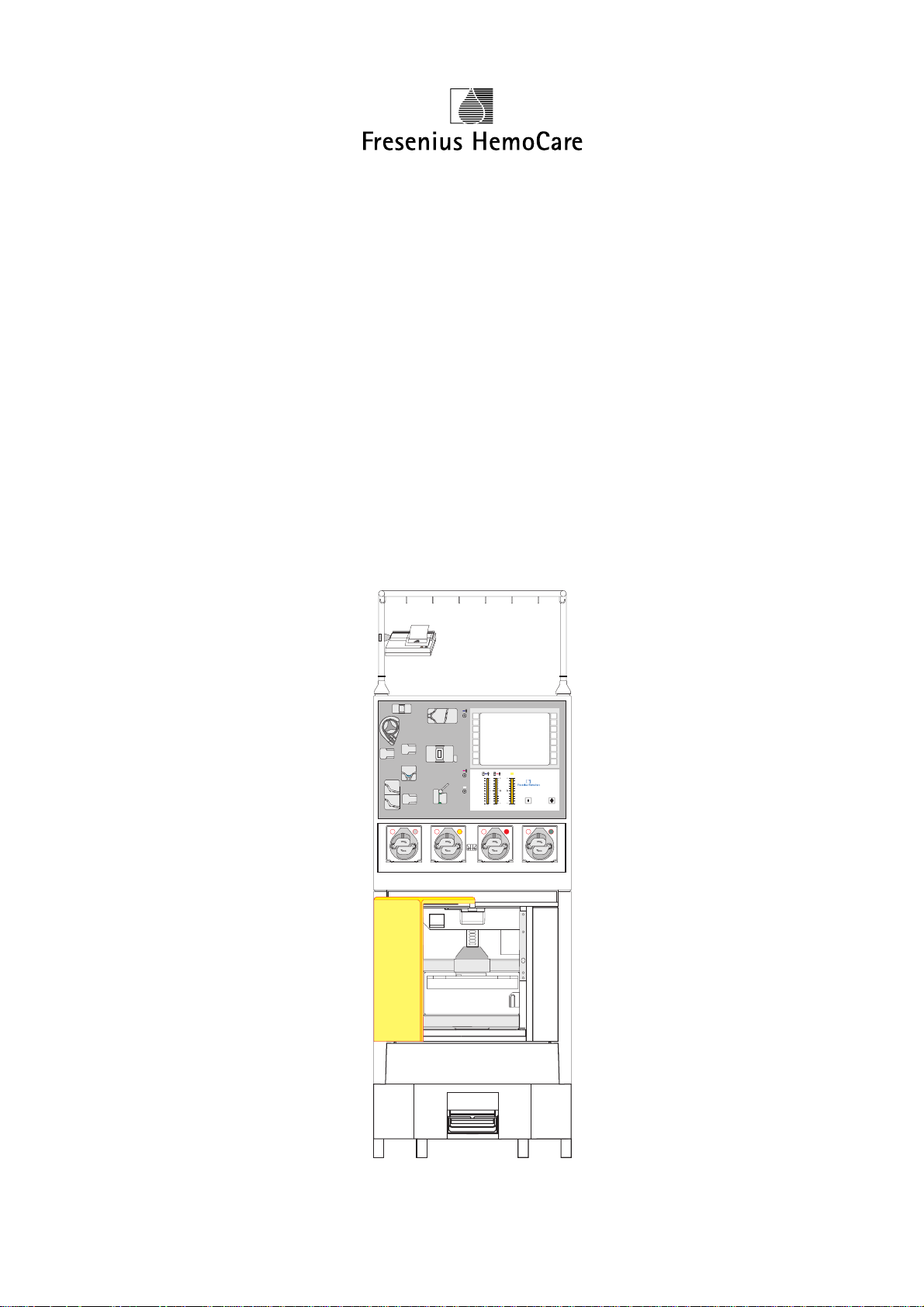
Fresenius
N
O
F
F
O
PP
P3
P3
COM.TEC
Part No. 679 469 1
Fresenius HemoCare COM.TEC 1/04.01 (TM) 0-1
Page 2

Any inquiries should be addressed to:
Manufacturer:
Fresenius HemoCare Deutschland GmbH
Produktionsbereich Geräte
Hafenstrasse 9
D-97424 Schweinfurt
Tel.: ++49 9721/678-0
Fax: ++49 9721/678-200
National Service:
Fresenius Transfusions GmbH
Landsteinerstrasse 5
D-63303 Dreieich
Tel.: ++49 6103/801-0
Fax: ++49 6103/801-672
0-2 Fresenius HemoCare COM.TEC 1/04.01 (TM)
Page 3

How to Use the Technical Manual
Search and Find What? Where?
Table of contents Page 0-5 and at the beginning of each chapter
Intended Use This manual is intended for:
– first studies (to acquire a basic knowledge)
– reference purposes (for start-up, maintenance and repair)
Organization The manual is divided into 6 chapters:
0 General Information
1 Config.Sys, Service.Sys, CCS Program
2 Repair / Adjustment / Maintenance
3 Circuit Descriptions and Circuit Diagrams
4 Spare Parts Catalog
5 Start-up and TSC
Page Identification Page identification 1-3 is to be interpreted as: Chapter 1, page 3.
Qualification This manual is intended to assist service technicians and assumes the following:
– that the user is familiar with the current operating instructions
– that he has the necessary background experience in mechanics, electrical
engineering and medical engineering;
– that he has been authorized by the manufacturer to perform maintenance and
repair work;
– that he has access to the necessary auxiliary and measuring equipment.
Limitations This manual is not intended to provide an alternative to instruction courses
offered by the manufacturer.
Manual changes Manual changes will be released as new editions, supplements or product
information.
Note:
Any modifications to circuit and component layout diagrams (SP/BP) do not
always affect footers (edition).
The current state of these diagrams is indicated in the index field of each
respective SP/BP.
The user/technician can use the respective marking on the printed circuit board
to verify whether the SP/BP comply with the actually existing printed circuit board
in the machine.
In general, this manual will be subject to modification.
Fresenius HemoCare COM.TEC 1/04.01 (TM) 0-3
Page 4

Specification Unless otherwise specified, potentials indicated in circuit diagrams and calibra-
tion instructions are related to the perinent ground.
For example, 24 means ground for the 24 V voltage.
Component Example:
identification in
circuit diagrams
This refers to a resistor with position number 75 and a resistance of 1.2 ohm.
The decimal point used to indicate the value is replaced by a unit symbol (to
reduce the possibility of errors).
Resistors Capacitors:
R1: 0.1 Ωµ 1: 0.1 µF
1R2: 1.2 Ω 1µ2: 1.2 µF
1K2: 1.2 kΩ 1000µ: 1000µF
Note When repairing blood cell separators and replacing spare parts, observe the
protective ESD measures to be taken to prevent electrostatic discharge (e.g.
EN 100015-1).
75
1R2
Technical Data The technical data of the COM.TEC Blood Cell Separator are listed in the
Operating Instructions.
0-4 Fresenius HemoCare COM.TEC 1/04.01 (TM)
Page 5

Table of Contents
Chapter Page
1 Config.Sys, Service.Sys, CCS Program ..................................................................... 1-
1.1 Config.sys ....................................................................................................................... 1-3
1.2 Service.sys...................................................................................................................... 1-9
1.3 PC E53............................................................................................................................ 1-11
1.4 SERVICE TOOL for COM.TEC....................................................................................... 1-13
2 Repair / Adjustment / Maintenance ............................................................................. 2-
2.1 Verification of the Interface Detection ............................................................................. 2-5
2.2 Adjustment of the Interface Detection............................................................................. 2-12
2.3 C5 Interface Sensitivity ................................................................................................... 2-22
2.4 Verification of the C5 Illuminance ................................................................................... 2-24
2.5 Inlet Pressure Monitor ..................................................................................................... 2-26
2.6 Outlet Pressure Monitor .................................................................................................. 2-31
2.7 P3 Monitor....................................................................................................................... 2-36
2.8 Operating Voltages / Battery Voltage ............................................................................. 2-41
2.9 Air Detector ..................................................................................................................... 2-42
2.10 Optical Detector in Air Detector ...................................................................................... 2-44
2.11 Hb/Hct Detector .............................................................................................................. 2-45
2.12 Spillover Detector ........................................................................................................... 2-47
2.13 Substituate-Empty Detector............................................................................................ 2-49
2.14 Gap Width of Outlet Clamp ............................................................................................. 2-51
2.15 Line Pumps ..................................................................................................................... 2-52
2.16 Clamps............................................................................................................................ 2-55
2.17 Centrifuge Door............................................................................................................... 2-57
2.18 Door Switch..................................................................................................................... 2-59
2.19 Centrifuge Motor Carbon Brushes .................................................................................. 2-61
2.20 Single Needle / Cuff Control ........................................................................................... 2-62
2.21 Removal and Installation of the Centrifuge Rotor .......................................................... 2-64
2.22 Tightening the Belts in the Rotor .................................................................................... 2-68
2.23 Brake............................................................................................................................... 2-69
2.24 Flutter Detector ............................................................................................................... 2-70
2.25 General Mechanical Checks ........................................................................................... 2-71
3 Circuit Descriptions and Circuit Diagrams ............................................................... 3-
3.1 Rear View of the COM.TEC Housing Top Part .............................................................. 3-3
3.2 Rear View of the COM.TEC Housing Bottom Part ........................................................ 3-4
3.3 COM.TEC Block Diagram ............................................................................................... 3-5
3.4 CAN Chain Block Diagram.............................................................................................. 3-7
3.5 Block Diagram of the Power Supply Separation
COM.TEC Control and Safety System ........................................................................... 3-9
3.6 Voltage Supply Block Diagram ....................................................................................... 3-11
3.7 P.C.B. LP-Z 175 Single Needle ...................................................................................... 3-13
3.8 P.C.B. LP-Z 241 Air Monitoring System.......................................................................... 3-17
3.9 P.C.B. LP 821 CAN/PC Card .......................................................................................... 3-23
3.10 P.C.B. LP 822 Keyboard Board ...................................................................................... 3-29
3.11 P.C.B. LP 823-1 Power Control Logic and Door Switch ................................................ 3-33
3.12 P.C.B. LP 826 Power Module Box .................................................................................. 3-43
3.13 P.C.B. LP 828 Dual Stroboscope.................................................................................... 3-49
3.14 P.C.B. LP 829 Flash Tube Board.................................................................................... 3-55
3.15 P.C.B. LP 830 CAN-I/O Card.......................................................................................... 3-59
3.16 P.C.B. LP 840 Alarm System.......................................................................................... 3-67
3.17 P.C.B. LP 841 Safety System ......................................................................................... 3-77
Fresenius HemoCare COM.TEC 1/04.01 (TM) 0-5
Page 6

Chapter Page
3.18 P.C.B. LP 852 Pump Control .......................................................................................... 3-83
3.19 P.C.B. LP 854 Logik Centrifuge Control Logic............................................................... 3-87
3.20 P.C.B. LP 855 Centrifuge Control................................................................................... 3-91
3.21 P.C.B. LP 857 Supply Voltage........................................................................................ 3-97
3.22 P.C.B. LP 860 Camera Logic.......................................................................................... 3-103
3.23 P.C.B. LP 861 Camera Sensor ....................................................................................... 3-107
3.24 P.C.B. LP 863 Interface Detection.................................................................................. 3-111
3.25 P.C.B. LP 864 Computer Bus Board............................................................................... 3-115
3.26 P.C.B. LP 865 Electronics Bus Board............................................................................. 3-119
3.27 P.C.B. LP 866 COM.TEC-I/O Card................................................................................. 3-123
3.28 P.C.B. LP 867 ACD Pump Unit....................................................................................... 3-133
3.29 P.C.B. LP 868 Camera Lighting...................................................................................... 3-145
3.30 P.C.B. LP 869 Clamp Control ......................................................................................... 3-149
3.31 P.C.B. LP 870 Pressure Monitor..................................................................................... 3-159
3.32 P.C.B. LP 945 Printer Adapter (Seiko) ........................................................................... 3-169
4 Spare Parts Catalog...................................................................................................... 4-
5 Start-Up and TSC .......................................................................................................... 5-
5.1 Instructions for Initial Start-Up ........................................................................................ 5-3
5.2 Technical Safety Checks ................................................................................................ 5-7
0-6 Fresenius HemoCare COM.TEC 1/04.01 (TM)
Page 7

Table of Contents
1 Config.Sys, Service.Sys, CCS Program
Chapter Page
1.1 Config.sys...................................................................................................................... 1-3
1.1.1 Configuration Donation ................................................................................................... 1-4
1.1.2 Configuration Therapy .................................................................................................... 1-7
1.1.3 Configuration General..................................................................................................... 1-8
1.2 Service.sys .................................................................................................................... 1-9
1.2.1 Display ............................................................................................................................ 1-10
1.2.2 IF set ............................................................................................................................... 1-10
1.2.3 max. RPM ....................................................................................................................... 1-10
1.2.4 Machine No..................................................................................................................... 1-10
1.2.5 Max. temp ....................................................................................................................... 1-10
1.2.6 Expertmode..................................................................................................................... 1-10
1.2.7 DCS ................................................................................................................................ 1-10
1.3 PC E53............................................................................................................................ 1-11
1.3.1 Flash Disc ....................................................................................................................... 1-11
1.3.2 PCMCIA Card ................................................................................................................. 1-11
1.3.3 Signals ............................................................................................................................ 1-12
1.3.4 BIOS Setup ..................................................................................................................... 1-12
1.4 SERVICE TOOL for COM.TEC ...................................................................................... 1-13
1.4.1 How to access the SERVICE TOOL for COM.TEC ....................................................... 1-13
1.4.2 Working with the CCS Program ...................................................................................... 1-14
1.4.3 Power Supply.................................................................................................................. 1-15
1.4.4 Pumps ............................................................................................................................. 1-16
1.4.5 Clamps............................................................................................................................ 1-17
1.4.6 ASTEC IO1 ..................................................................................................................... 1-18
1.4.7 ASTEC IO2 ..................................................................................................................... 1-20
1.4.8 HBHK / spillover.............................................................................................................. 1-21
1.4.9 CCD Camera .................................................................................................................. 1-22
Fresenius HemoCare COM.TEC 1/04.01 (TM) 1-1
Page 8

1-2 Fresenius HemoCare COM.TEC 1/04.01 (TM)
Page 9
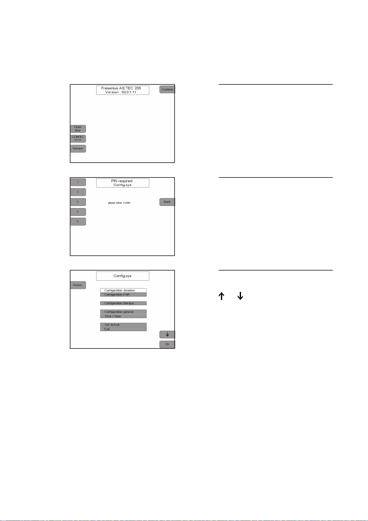
1.1 Config. Sys
The basic configuration of the COM.TEC can be changed in the Config.sys.
Display
Press the CONFIG.SYS key.
Display
Enter the code 1 3 5 2 4
with the numeric keys.
The Config.Sys codes can be entered as
often as desired.
The Config.Sys screen displays.
Select the desired configuration with the
and keys.
Press the OK key.
The selected menu option displays.
Fresenius HemoCare COM.TEC 1/04.01 (TM) 1-3
Page 10

1.1.1 Configuration Donation
Display
Select the values to be altered by press-
ing the and keys.
Alter the values by pressing the + and –
keys.
Press the OK key to save all changes.
To exit the configuration menu and to re-
turn to the previous screen, press the
Back key.
– Menu
Donor menu and donor data display can be activated and deactivated.
– PLT pre
Presetting of the donor’s mean platelet pre-value.
– HCT pre
Presetting of the donor’s mean HCT pre-value.
– Max. ACD-rate
Setting of the ACD rate per liter of whole blood volume tolerated by the donor.
– ACD:RBC
The ACD:RBC ratio influences the ACD: WB ratio based on the hematocrit. The pH value is
optimized in the storage bag.
– Coeff. DN
Operand for adapting the yield to the predicted value.
– Coeff. SN
Operand for adapting the yield to the predicted value.
– F(return)SN
Adjustment of the return flow rate to the donor.
1-4 Fresenius HemoCare COM.TEC 1/04.01 (TM)
Page 11

– F(return)PLS
Adjustment of the blood pump flow during the SN return phase with active plasma collection.
– PLS-Coll.DN
Preselection of automatic plasma collection and selection of the volume to be separated (Off
= 0). Dual needle.
– PLS-Coll.SN
Preselection of automatic plasma collection and selection of the volume to be separated (Off
= 0). Single needle.
– Get sample
Selection and deselection of help texts for sample collection. Single needle.
– F(cell) return SN
Factor for the cell flow in the return phase. Single needle.
– max. PC-Vol
Determination of the maximum collection volume for the platelet concentrate.
– default PC-Vol
Selection of the standard PC volume.
– Yield
Preadjustment of the platelet yield.
– min. PLT post
Threshold for the donor’s PLT-post value which causes a warning when reached.
– F PC deaerate
Selection of the plasma pump flow during deaeration of the platelate concentrate
(Off = 0)
Fresenius HemoCare COM.TEC 1/04.01 (TM) 1-5
Page 12

● Increments and limits for donation parameter configuration
Default Increment Max. Min.
Menus On – On Off
PLTpre 265 x E9/L 1 x E9/L 400 x E9/L 100 x E9/L
HCT pre 40% 1% 60% 20%
max. ACD-rate 1.1ml/min/L 0.1 ml/min/L 2.2 ml/min/L 0.1 ml/min/L
ACD:RBC 1:3.2 0.1 1:5.0 1:2.0
Coeff. DN 49% 1% 70% 30%
Coeff. SN 59% 1% 70% 30%
F(return) SN 75 ml/min 1 ml/min 200 ml/min 50 ml/min
F(return) PLS 35 ml/min 1 ml/min 70 ml/min 35 ml/min
PLS-Coll. DN Off 10 ml 500 ml Off, 50 ml
PLS-Coll. SN Off 10 ml 500 ml Off, 50 ml
Get sample On – On Off
F(cell) return SN 0.7*F(c) coll 0.1*F(c)coll 2.0*F(c)coll 0.1*F(c)coll
max. PC-Vol 600 ml 10 ml 1500 ml 600 ml
default PC-Vol 250 ml 10 ml 600 ml 100 ml
Yield 300 x E9 10 x E9 1500 x E9 50 x E9
min. PLT post 80 E9/L 1 E9/L 150 E9/L 50 E9/L
F PC deaerate 50 ml/min 1 ml/min 120 ml/min Off, 10 ml
1-6 Fresenius HemoCare COM.TEC 1/04.01 (TM)
Page 13

1.1.2 Configuration Therapy
– Menus
Selection and deselection of the TPE and RBC menus.
– HCT pre
Preadjustment of the patient’s hematocrit value for calculation of the menus.
– HCT RBC
Preadjustment of the hematocrit value, which is adjusted by the Hct controller (see controller
options) in the RBC line. During the RBC procedure, this value is computed and changed
correspondingly by the menu.
Display
Fresenius HemoCare COM.TEC 1/04.01 (TM) 1-7
Page 14
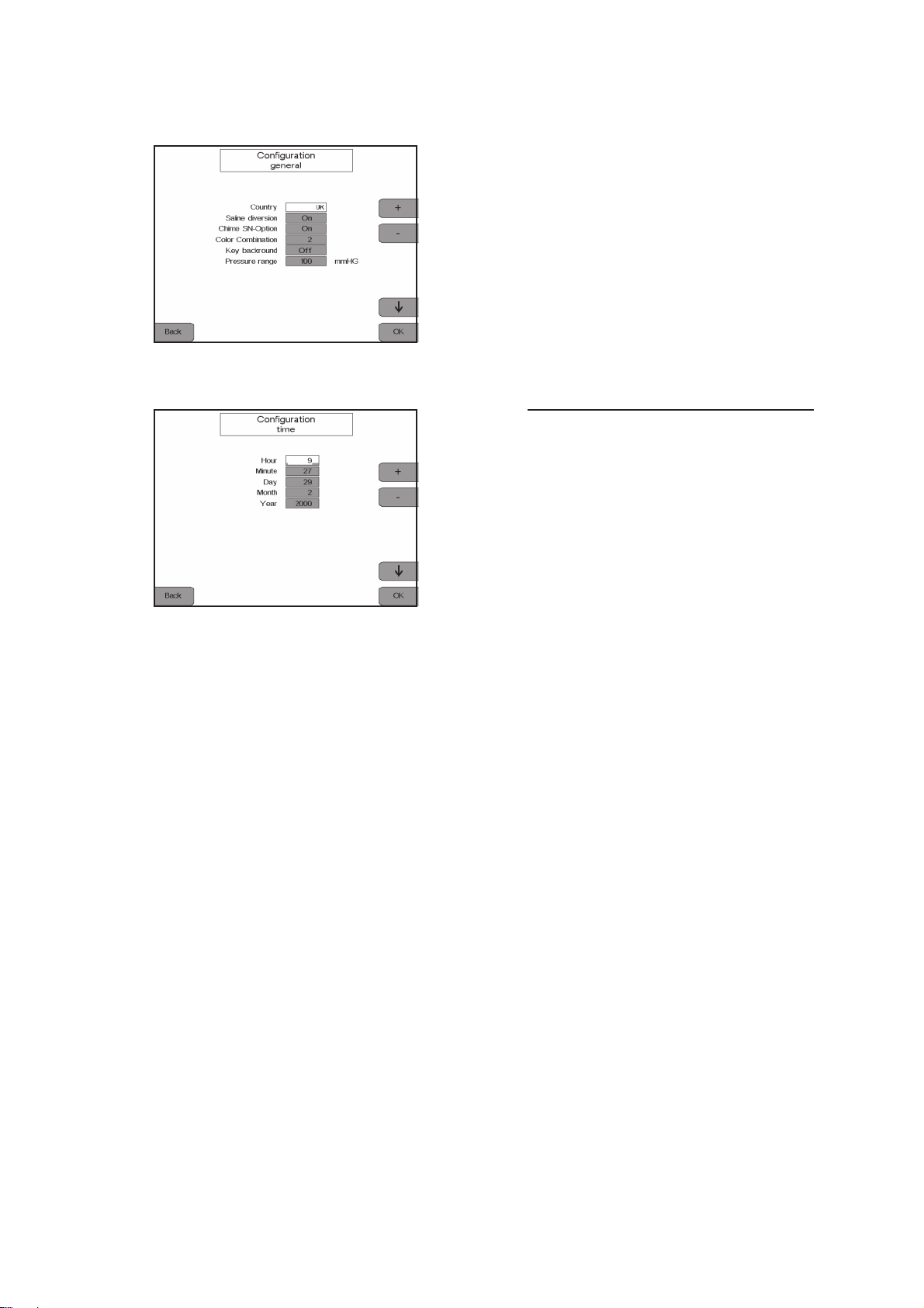
1.1.3 Configuration General
– Configuration time
Setting of year, day, hour, minute.
– Country
The country version changes language, units and clock to national conventions.
– Saline diversion
Activates and deactivates saline diversion.
– Chime SN-Option
Activates the chime if no automatic cuff is used.
– Colour combination
Setting the colour combination of the display.
– Key background
Switching the key background on and off.
– Pressure range
Selects the pressure range for the inlet pressure monitor which initiates a pre-alarm if the inlet
pressure drops.
Default: 100 mmHg
1-8 Fresenius HemoCare COM.TEC 1/04.01 (TM)
Page 15
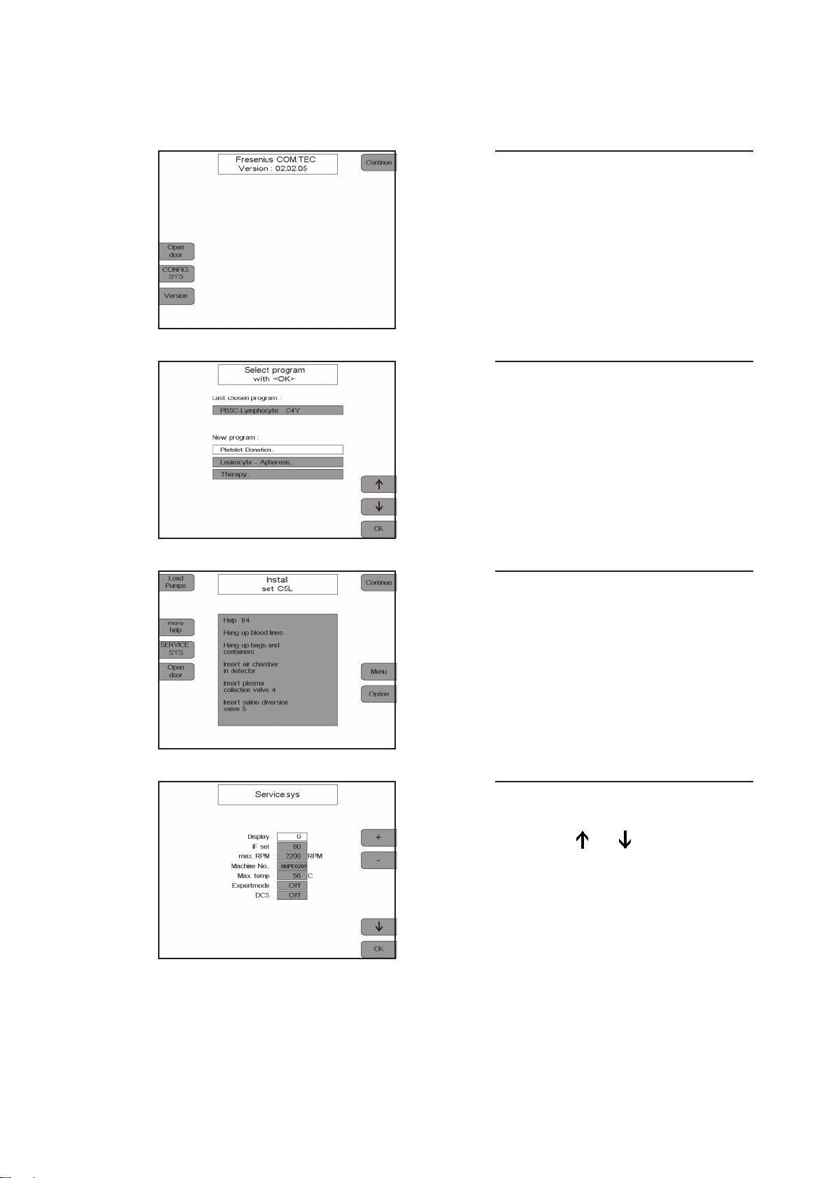
1.2 Service.sys
Display.
Press the Continue key.
Display.
Press the 2nd, the 4th and the 1st key to
the left of the display one after the other.
Press the OK key.
Display.
Press the SERVICE.SYS key.
The Service.Sys screen is displayed.
Select the desired program item by
pressing the and keys.
Fresenius HemoCare COM.TEC 1/04.01 (TM) 1-9
Page 16

1.2.1 Display
Selection of the program phase window
1.2.2 IF set
Adjustment of the interface sensitivity
1.2.3 max. RPM
Maximum centrifuge speed set to 2200 rpm
1.2.4 Machine No.
Possibility to enter the machine no. shown on the type label
1.2.5 Max. temp
Indication of the maximum temperature that prevailed inside the centrifuge
1.2.6 Expertmode
Possibility to create RAM programs
1.2.7 DCS
Activation/deactivation of the optional radio communication interface
1-10 Fresenius HemoCare COM.TEC 1/04.01 (TM)
Page 17
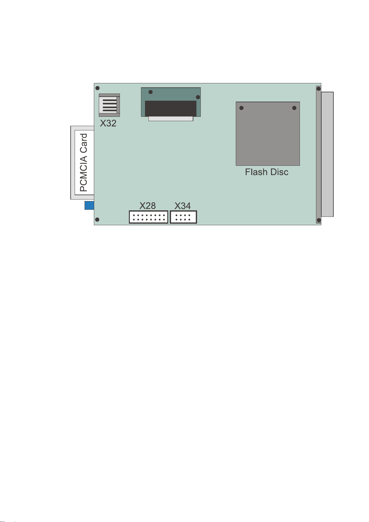
1.3 PC E53
Fig.: PC E53
1.3.1 Flash Disc
The Flash Disc is incorporated as system drive C:\ and contains the DOS system, the program
control and display software.
1.3.2 PCMCIA Card
The PCMCIA Card is incorporated in the system as drive C:\. In this case, the Flash Disc
automatically becomes drive D:\.
The PCMCIA Card contains the current program control and display software (in case of a
software update) and the diagnosis/service program.
Fresenius HemoCare COM.TEC 1/04.01 (TM) 1-11
Page 18

1.3.3 Signals
LCD/X33
PIN Signal
1VS
2HS
3 VCKL
4nc
5nc
6 _Blank
7nc
8 VID
9nc
– nc
1.3.4 BIOS Setup
The BIOS setup is accessed by pressing the Ctrl + Alt + F6 keys, when turning power on to the
COM.TEC.
X32
PIN Signal
1 GND
2 DATA
3 VCC
4 CLK
E 5 3 S E T U P P R O G R A M
DISK DRIVE 0 TYP 0: NOT INSTALLED
DISK DRIVE 1 TYP 0: NOT INSTALLED
PCMCIA - ATA / IDE BOOT DRIVE SELECT
BOOT FROM 1: ATA-CARD ATA-BIOS EXT : YES
SHOW BOOT MESSAGES: NO KEYBOARD TEST: NO
SELECT DISPLAY TYPE: AUTO
POST WAIT TIME IN SECONDS: 00
BOOT FROM: HARD DISC
CTL ALT DEL RESET: ACTIVATE HW
COM3 / COM4 IRQ: 4 / 3
ALL INPUTS ARE CORRECT? (1)
KEYS: <↑> CHANGE VALUE, <RET> NEXT ITEM
1-12 Fresenius HemoCare COM.TEC 1/04.01 (TM)
Page 19

1.4 SERVICE TOOL for COM.TEC
1.4.1 How to access the SERVICE TOOL for COM.TEC
– Turn the COM.TEC power off.
– Insert the PCMCIA card in the PC.
– Connect the external keyboard to X32 / PC.
– Turn the COM.TEC power on.
– Press the key.
– The Service Tool for COM.TEC screen displays.
– The following options are available:
Menu key Menu key Menu key
Service Tool S
Update U Software Update to A Select BIOS Version
BIOS E53 00.01.06 A
BIOS E53 00.01.07 B
System Config C Install DCS Driver I
Deinstall DCS Driver D
Exit Update E
EXIT UPDATE E
– The desired option is selected by pressing the associated key.
Fresenius HemoCare COM.TEC 1/04.01 (TM) 1-13
Page 20
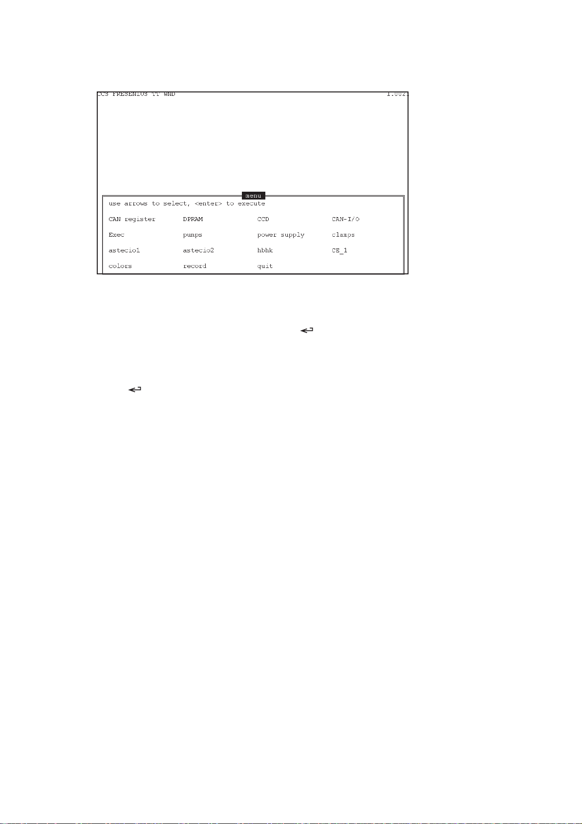
1.4.2 Working with the CCS program
– Use the cursor to select the desired menu.
– Display the menu selected by pressing the key.
– Press the Esc key to exit the respective menu.
– To exit the CCS program, select quit using the cursor and confirm this selection by pressing
the key.
– Within the CCS program, menu-specific help is available, which can be displayed by pressing
the F1 key.
1-14 Fresenius HemoCare COM.TEC 1/04.01 (TM)
Page 21
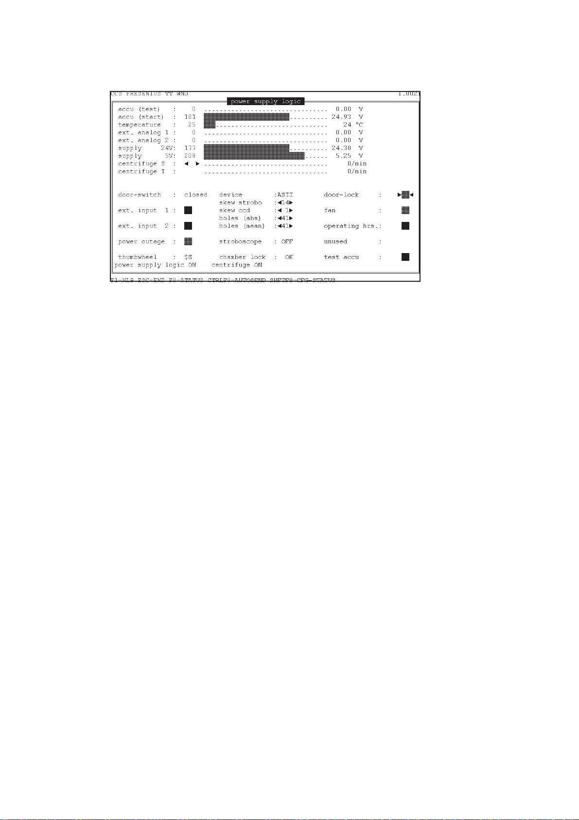
1.4.3 Power Supply
accu (test): battery voltage during the battery test
accu (start): battery voltage
temperature: temperature of power supply unit
supply 24 V: current value of the 24-V supply voltage
supply 5 V: current value of the 5-V supply voltage
centrifuge S: target centrifuge speed; see help menu for adjustment
centrifuge I: actual centrifuge speed
door-switch: door switch display: close - alarm - open
device: must be set to AS II
door-lock: door opener
fan: activation/deactivation of the fan
operating hrs.: activation/deactivation of the time meter
test accu: activation of the battery test
Fresenius HemoCare COM.TEC 1/04.01 (TM) 1-15
Page 22
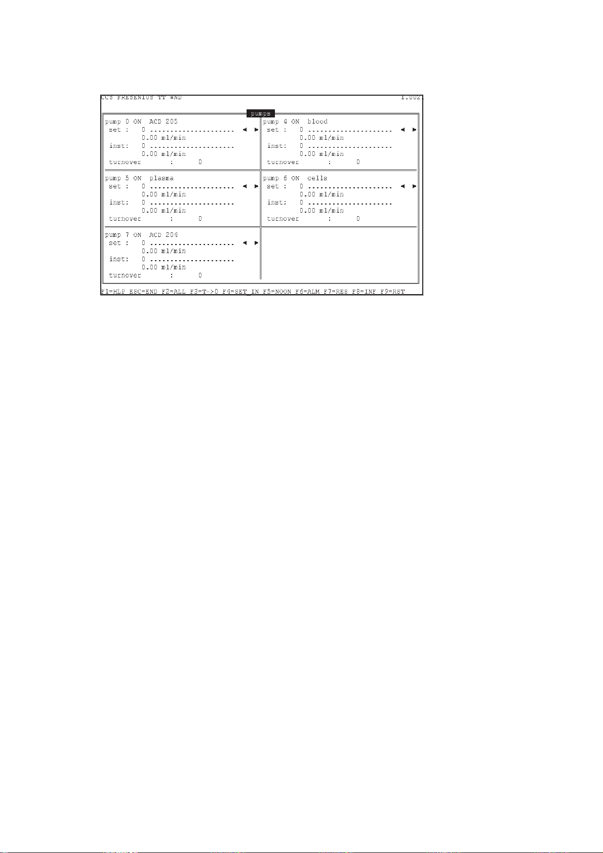
1.4.4 Pumps
Pins 9 and 10 of relay RL 300 / P.C.B. LP 823-1 must be bridged to activate the pumps.
set: target speed in digits; see help menu for adjustment
inst: actual speed in digits
turnover: number of rotor revolutions
cover closed: pump cover display: close - alarm
1-16 Fresenius HemoCare COM.TEC 1/04.01 (TM)
Page 23
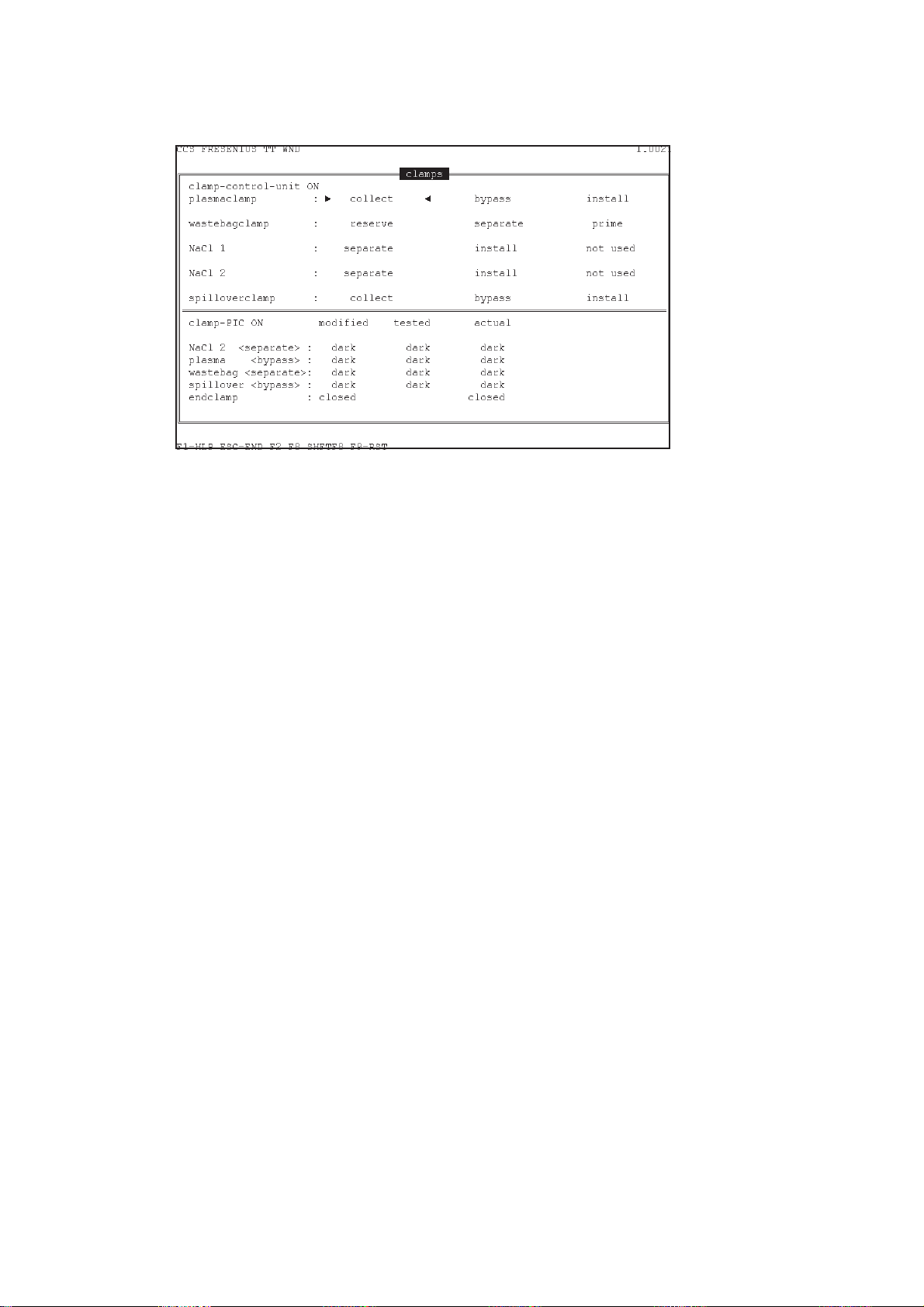
1.4.5 Clamps
clamp-control-unit: clamp-control-unit display: on - off
plasmaclamp: position of the plasma collection clamp
wastebagclamp: position of the saline diversion clamp
NaCl 1: position of the saline clamp in the inlet line
NaCl 2: position of the saline clamp in the return line
spilloverclamp: position of the collection / return clamp
Fresenius HemoCare COM.TEC 1/04.01 (TM) 1-17
Page 24
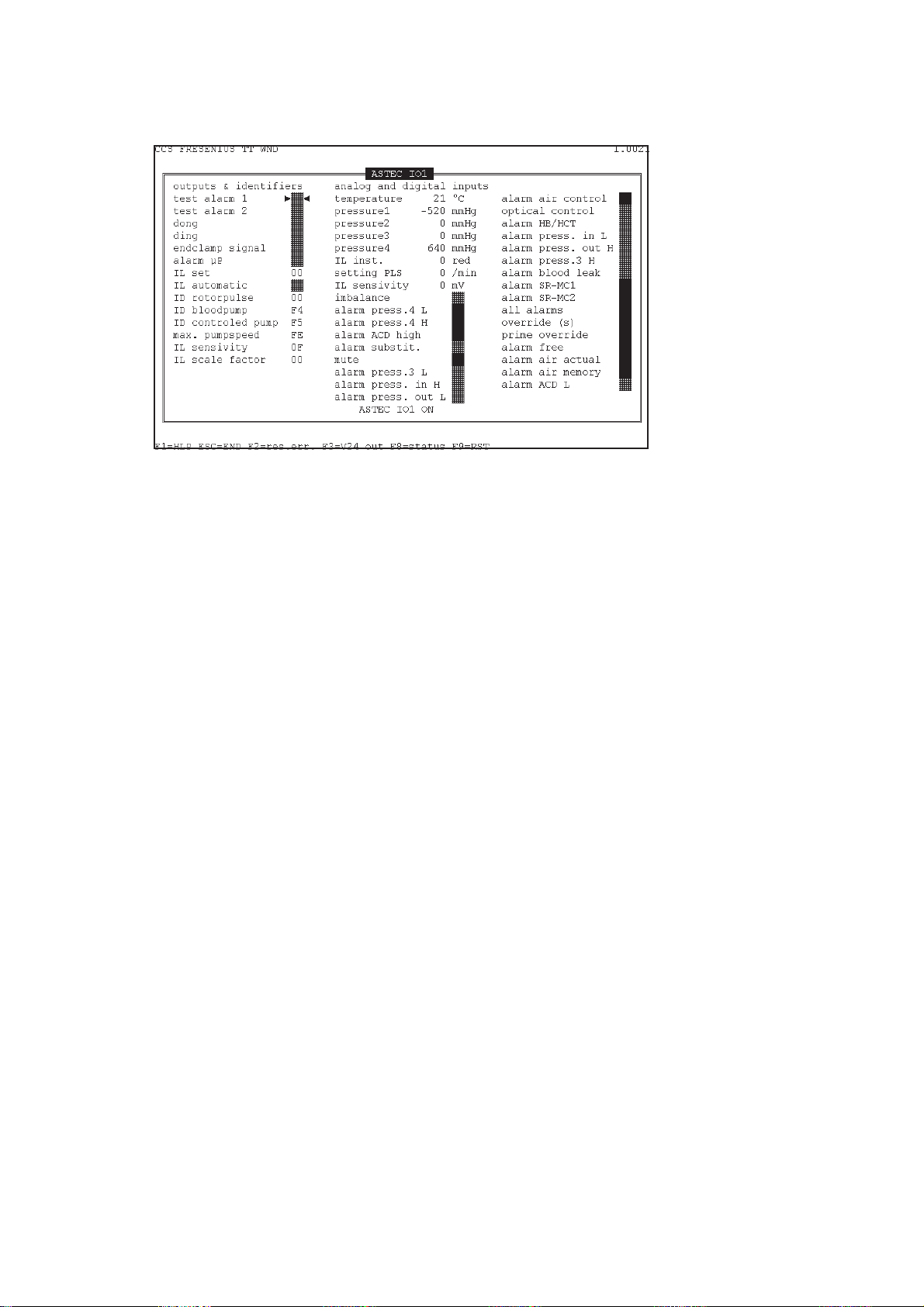
1.4.6 ASTEC IO1
Digital outputs and identifier:
test alarm 1: initiates the alarm test
test alarm 2: cancels stored alarms
dong: deep signal tone
ding: high signal tone
endclamp signal: opens the return clamp of the air detector if no alarm is pending and if
alarm µP: alarm-free if the output is set
IL set: target value of the interface position
IL automatic: interface controller
ID rotorpulse: CAN identifier; do not change
ID bloodpump: CAN identifier; do not change
ID controlled pump: CAN identifier; do not change
max pumpspeed: max. speed of the pump; do not change
IL sensitivity: sensitivity of the interface
IL scale factor: activation of the interface control by the PLS pump
alarm µP is set
Analog inputs:
temperature: temperature inside the centrifuge
pressure 1: P3 pressure value
pressure 2: inlet pressure value
pressure 3: return pressure value
pressure 4: reserve pressure channel value
IL inst.: number of red holes of the interface detection
setting PLS: target value of the PLS pump
IL sensitivity: value of the control voltage
1-18 Fresenius HemoCare COM.TEC 1/04.01 (TM)
Page 25

Digital inputs:
imbalance: imbalance alarm
alarm press. 4 L: alarm pressure 4 too low
alarm press 4 H: alarm pressure 4 too high
alarm ACD high: alarm ACD ratio too high
alarm substit.: alarm no replacement fluid
mute: mute alarm tone generator
alarm press. 3 L: alarm pressure P3 too low
alarm press in H: alarm inlet pressure too high
alarm press. out L: alarm return pressure too low
air control: alarm air detector
optical control: optical detector of the return clamp of the air detector
alarm HB/HK: alarm hemolysis
alarm press. in L: alarm inlet pressure too low
alarm press. out H: alarm return pressure too high
alarm press. 3 H: alarm pressure P3 too high
alarm blood leak: alarm blood leak
alarm SR-MC 1: alarm safety system, channel 1
alarm SR-MC 2: alarm safety system, channel 2
all alarms: all alarms are active (scanned during the alarm test)
override(s): brief overriding of alarms (to fill the drip chamber)
prime override: overriding of alarms during priming
alarm alarm free: no alarm is pending
alarm air actual: current air detector alarm
alarm air memory: stored air detector alarm
alarm ACD L: alarm - ACD ratio too low
Fresenius HemoCare COM.TEC 1/04.01 (TM) 1-19
Page 26

1.4.7 ASTEC IO2
cuff pump: activates the single-needle pump
cuff valve: activates the single-needle valve (the end clamp must also be activated)
endclamp signal: end clamp signal for single-needle control
pressure: indicates whether the pressure has been achieved
cuff present: single-needle assembly P.C.B. LP-Z 175 present
1-20 Fresenius HemoCare COM.TEC 1/04.01 (TM)
Page 27

1.4.8 HBHK / spillover
ACD drops: number of ACD drops
EEPROM: indicates position of switch S1 / LP 867
substituade: status of substituate-empty detector
HBHK: Hb/Hk detector
spillover: spillover detector
dimming: dimness of detector in digits
coloring: coloring of detector in digits
alarm: Alarm Hb/Hk or Spillover
is adj.: lights after adjustment of the reference value
adj.: lights during adjustment of the reference value
is calib.: lights after calibration
calib: lights during calibration
Fresenius HemoCare COM.TEC 1/04.01 (TM) 1-21
Page 28

1.4.9 CCD camera
loop control: –
chamberlight: chamber light on - off
mirrorlight: mirror light on - off
initsearch: initialisation phase on - off
automatic: automatic position test on - locked
holeskew: hole skew, camera trigger
startpixel: start pixel, interface window
resetcounter: number of camera resets
edgepixelval.: –
ADC ref. low: reference voltage low
ADC ref. high: reference voltage high
lighttime ml.: mirror light exposure time
lighttime cl.: chamber light exposure time
errorbyte: internal display error counter
set. line: target interface value
interfaceline: actual interface value
pmp max.: –
set. pmp: –
1-22 Fresenius HemoCare COM.TEC 1/04.01 (TM)
Page 29

Table of Contents
2 Repair / Adjustment / Maintenance
Chapter Page
2.1 Verification of the Interface Detection ........................................................................ 2-5
2.1.1 Verification of the Optical Sensor ................................................................................... 2-6
2.1.2 Verification of the 8 Hole Pulses ..................................................................................... 2-7
2.1.3 Verification of the Interface Sensitivity of the 8 Hole Pulses ......................................... 2-9
2.1.4 Verification of the C5 Interface Detection ....................................................................... 2-10
2.2 Adjustment of the Interface Detection ........................................................................ 2-12
2.2.1 Adjustment of the Optical Sensor ................................................................................... 2-13
2.2.2 Basic Adjustment of the Camera and the Lighting Unit ................................................. 2-14
2.2.3 Precision Adjustment of the Camera and the Lighting Unit ........................................... 2-15
2.2.4 Adjustment of the 8 Hole Pulses (Basic Adjustment C5 Detection) .............................. 2-17
2.2.5 Adjustment of the Interface Sensitivity of the 8 Hole Pulses ......................................... 2-18
2.2.6 Adjustment of the C5 Interface Detection ....................................................................... 2-19
2.3 C5 Interface Sensitivity ................................................................................................ 2-22
2.3.1 Verification of the C5 Interface Sensitivity ...................................................................... 2-22
2.3.2 Adjustment of the C5 Interface Sensitivity ...................................................................... 2-23
2.4 Verification of the C5 Illuminance ............................................................................... 2-24
2.5 Inlet Pressure Monitor .................................................................................................. 2-26
2.5.1 Verification of the Gain ................................................................................................... 2-26
2.5.2 Verification of the Alarm Limits ....................................................................................... 2-26
2.5.3 Adjustment of the Gain ................................................................................................... 2-27
2.5.4 Adjustment of the Alarm Limits ....................................................................................... 2-29
2.6 Outlet Pressure Monitor ............................................................................................... 2-31
2.6.1 Verification of the Gain ................................................................................................... 2-31
2.6.2 Verification of the Alarm Limits ....................................................................................... 2-31
2.6.3 Adjustment of the Gain ................................................................................................... 2-32
2.6.4 Adjustment of the Alarm Limits ....................................................................................... 2-34
2.7 P3 Monitor ..................................................................................................................... 2-36
2.7.1 Verification of the Gain ................................................................................................... 2-36
2.7.2 Verification of the Alarm Limits ....................................................................................... 2-36
2.7.3 Adjustment of the Gain ................................................................................................... 2-37
2.7.4 Adjustment of the Alarm Limits ....................................................................................... 2-39
2.8 Operating Voltages / Battery Voltage ......................................................................... 2-41
2.8.1 Verification ...................................................................................................................... 2-41
2.9 Air Detector ................................................................................................................... 2-42
2.9.1 Verification ...................................................................................................................... 2-42
2.9.2 Adjustment ...................................................................................................................... 2-43
2.10 Optical Detector in Air Detector .................................................................................. 2-44
2.10.1 Verification ...................................................................................................................... 2-44
2.10.2 Calibration of the Optical Detector.................................................................................. 2-44
Fresenius HemoCare COM.TEC 1/04.01 (TM) 2-1
Page 30

Chapter Page
2.11 Hb/Hct Detector............................................................................................................. 2-45
2.11.1 Verification ...................................................................................................................... 2-45
2.11.2 Adjustment...................................................................................................................... 2-46
2.12 Spillover Detector ......................................................................................................... 2-47
2.12.1 Verification ...................................................................................................................... 2-47
2.12.2 Adjustment...................................................................................................................... 2-48
2.13 Substituate-Empty Detector ........................................................................................ 2-49
2.18.1 Verification ...................................................................................................................... 2-49
2.13.2 Adjustment...................................................................................................................... 2-50
2.14 Gap Width of Outlet Clamp .......................................................................................... 2-51
2.14.1 Verification of Gap Width ................................................................................................ 2-51
2.14.2 Verification of Line Occlusion ......................................................................................... 2-51
2.14.3 Adjustment...................................................................................................................... 2-51
2.15 Line Pumps.................................................................................................................... 2-52
2.15.1 Verification ...................................................................................................................... 2-52
2.15.2 Verification of the 5 Line Pumps..................................................................................... 2-53
2.15.3 Cleaning of the Pump Rotors and the Pump Beds........................................................ 2-53
2.15.4 Adjustment of the Pump Rotors Nr. 4, 5, 6, 7................................................................. 2-54
2.15.5 Final Check..................................................................................................................... 2-54
2.16 Clamps ........................................................................................................................... 2-55
2.16.1 Verification of the Occlusion Pressure of the Clamps ................................................... 2-56
2.17 Centrifuge Door............................................................................................................. 2-57
2.17.1 Removing the Door......................................................................................................... 2-57
2.17.2 Removing the Door Frame (Chassis) and the Pivot Bearing......................................... 2-57
2.17.3 Adjustment...................................................................................................................... 2-58
2.18 Door Switch ................................................................................................................... 2-59
2.18.1 Verification ...................................................................................................................... 2-59
2.18.2 Removal / Installation ..................................................................................................... 2-60
2.18.3 Adjustment...................................................................................................................... 2-60
2.19 Centrifuge Motor Carbon Brushes.............................................................................. 2-61
2.19.1 Verification ...................................................................................................................... 2-61
2.20 Single Needle / Cuff Control ........................................................................................ 2-62
2.20.1 Verifications .................................................................................................................... 2-62
2.20.2 Adjustment...................................................................................................................... 2-63
2.21 Removal and Installation of the Centrifuge Rotor .................................................... 2-64
2.21.1 Removal of the Centrifuge Rotor .................................................................................... 2-65
2.21.2 Installation of the Centrifuge Rotor ................................................................................. 2-66
2.22 Tightening the Belts in the Rotor ................................................................................ 2-68
2.21.1 Verification ...................................................................................................................... 2-68
2.22.2 Adjustment...................................................................................................................... 2-68
2.23 Brake .............................................................................................................................. 2-69
2.23.1 Removal / Installation ..................................................................................................... 2-69
2.23.2 Adjustment...................................................................................................................... 2-69
2-2 Fresenius HemoCare COM.TEC 1/04.01 (TM)
Page 31

Chapter Page
2.24 Flutter Detector ............................................................................................................. 2-70
2.24.1 Verification ...................................................................................................................... 2-70
2.25 General Mechanical Checks ........................................................................................ 2-71
2.25.1 Housing........................................................................................................................... 2-71
2.25.2 Rubber Pads ................................................................................................................... 2-71
2.25.3 Mounting Screws ............................................................................................................ 2-71
2.25.4 Optical Sensors............................................................................................................... 2-71
2.25.5 Fan.................................................................................................................................. 2-71
Fresenius HemoCare COM.TEC 1/04.01 (TM) 2-3
Page 32

2-4 Fresenius HemoCare COM.TEC 1/04.01 (TM)
Page 33

2.1 Verification of the Interface Detection
Measuring equipment: 2-channel storage oscilloscope,
CCD test adapter – camera (part no. 678 617 1),
BNC test cable (part no. 678 482 1),
Reference chamber (part no. M60 383 1),
Test cable (part no. 679 763 1)
Mode of operation: CCS program
Caution
Clean the optical axis prior to the verification of the interface detection.
– Access the CCS program.
– Select the power supply menu.
– The following screen displays:
Fresenius HemoCare COM.TEC 1/04.01 (TM) 2-5
Page 34

2.1.1 Verification of the Optical Sensor
Fig.: P.C.B. LP 823-1
– Stop the centrifuge (pos. 1), open the door (door lock).
– Connect the oscilloscope to P400 /LP 823-1 and GND / LP 823-1.
– Set the centrifuge speed to 1000 rpm.
P400
Gnd
Oscilloscope setting:
P400 / LP 823-1: 1 V/Div.
Time base: 0.5 ms/Div
– Check the optical sensor signal at 300 rpm and 2000 rpm.
Optical sensor signal:
Amplitude: >4.7 V
Pulse duty factor: 50 % ± 10 %
– Signal not flickering
– If the optical sensor signal deviates from the target values the interface detection must be
completely adjusted. (➜ Chapter 2.2).
2-6 Fresenius HemoCare COM.TEC 1/04.01 (TM)
Page 35

2.1.2 Verification of the 8 Hole Pulses
MP1
MP0
– Install the reference chamber with segment 1.
– Connect the test cable to connector X3 / LP 863.
– Connect the oscilloscope to the test adapter X3.2 / LP 863 (ground) and to X3.1 / LP 863 (hole
pulses).
– Connect the oscilloscope to MP 0 / LP 866 (ground) and to MP 1 / LP 866 (current of the
transmitting diode).
– Close the centrifuge door and set the centrifuge speed to 1000 rpm in the power supply
menu.
– Activate automatic sending of the target values (AUTOSEND) by pressing the Ctrl and the F8
key. Press the key.
– Exit the power supply menu and select the CAN-I/O menu.
– Activate the trigger unit output 2 / no. 0.
Note
☞
The current of the transmitting diode depends on the temperature. Before the
verification the centrifuge must therefore have been in operation for at least 10
minutes, with the trigger unit output 2 / no. 0 activated, and the current of the
transmitting diode must be 300 mA.
Fresenius HemoCare COM.TEC 1/04.01 (TM) 2-7
Page 36

Oscilloscope setting:
X3.1 / LP 863 2 V / Div
(hole pulses):
MP 1 / LP 866 0.1 V / Div
(current of the
transmitting diode):
Time base: 0.5 ms / Div
Triggering: current of the
transmitting diode,
ascending edge
– The 8 hole pulses must appear within the signal of the current of the transmitting diode (see
figure).
– Reduce the centrifuge speed to 300 rpm and then increase the speed to 2200 rpm. While
altering the speed, the 8 hole pulses must always be within the signal of the current of the
transmitting diode (see figure).
– If the 8 hole pulses are not within the signal of the current of the transmitting diode or if they
leave this signal when the speed is altered, the interface detection must be completely
adjusted (➜ Chapter 2.2).
2-8 Fresenius HemoCare COM.TEC 1/04.01 (TM)
Page 37

2.1.3 Verification of the Interface Sensitivity of the 8 Hole Pulses
– Stop the centrifuge (pos. 1), open the door (door lock ).
– Insert the reference chamber with the C4 hole area covered with adhesive foil (segment 2).
– Connect the oscilloscope to the test adapter X3.2 / LP 863 (ground) and to X3.4 / LP 863
(digital hole pulses).
– Connect the oscilloscope to MP 0 / LP 866 (ground) and MP 1 / LP 866 (current of the
transmitting diode).
– Close the door, set the centrifuge speed to 1000 rpm.
Oscilloscope setting:
MP 1 / LP 866 0.1 V / Div
(current of the
transmitting diode):
X3.4 / LP 863 2 V / Div
(digital
hole pulses):
Time base: 0.5 ms / Div
Triggering: current of the
transmitting diode,
ascending edge
Note
☞
– All of the 8 hole pulses (digital) must just be visible and may not flicker (see figure).
– If the 8 hole pulses (digital) are not visible or flicker, the interface detection must be completely
adjusted (➜ Chapter 2.2).
The current of the transmitting diode depends on the temperature. Before the
verification the centrifuge must therefore have been in operation for at least 10
minutes, with the trigger unit output 2 / no. 0 activated. The current of the
transmitting diode must be 300 mA.
Fresenius HemoCare COM.TEC 1/04.01 (TM) 2-9
Page 38

2.1.4 Verification of the C5 Interface Detection
– Stop the centrifuge (pos. 1), open the door (door lock).
– Insert the reference chamber segment 5.
– Connect the CCD test adapter to the plug connector that exits the camera housing.
– Connect the oscilloscope with the two BNC test cables to the CCD test adapter.
– Close the door, set the centrifuge speed to 2200 rpm.
– Exit the power supply menu and select the CCD menu.
– Press the F9 and the key to reset the camera and wait until the initialization phase of the
camera is completed (initsearch: OFF) and segment 5 of the reference chamber has been
detected (C5 detected: ON).
– Use the F3 key to set chamberlight: ON (lighting).
– Use the F6 key to set automatic: locked.
Caution
If the camera does not receive a new CAN command within one minute
(holeskew, lighttime cl, startpixel), it automatically exits the locked mode and
the display changes from automatic: locked to automatic: ON.
– Use the and keys to select holeskew and use the and key to set the value to 8
(reference signal).
– The C5 reference signal must appear within the gate pulse (see figure).
Oscilloscope setting:
Video signal: 0.5 V / Div
Gate pulse: 2 V / Div
Time base: 5 ms / Div
Triggering: gate pulse, ascending
edge
– If the C5 reference signal is not within the gate pulse, the interface detection must be
completely adjusted (➜ Chapter 2.2).
2-10 Fresenius HemoCare COM.TEC 1/04.01 (TM)
Page 39

– Use the and keys to select holeskew and use the and keay to set the value to 11
(C5 interface signal).
– The C5 interface signal must appear within the gate pulse (see figure).
Oscilloscope setting:
Video signal: 0.5 V / Div
Gate pulse: 2 V / Div
Time base: 5 ms / Div
Triggering: gate pulse, ascending
edge
– If the C5 interface signal is not within the gate pulse, the interface detection must be
completely adjusted (➜ Chapter 2.2).
– If the C5 interface signal is flickering, the interface detection need not be adjusted.
Fresenius HemoCare COM.TEC 1/04.01 (TM) 2-11
Page 40

2.2 Adjustment of the Interface Detection
Measuring equipment: 2-channel storage oscilloscope,
CCD test adapter – camera (part no. 678 617 1),
BNC test cable (part no. 678 482 1),
Reference chamber (part no. M60 383 1),
Test cable (part no. 679 763 1)
Mode of operation: CCS program
Caution
Before adjusting the interface detection:
– Check the belt tension and adjust, if necessary.
– Clean the optical axis.
– Access the CCS program.
– Select the power supply menu.
– The following screen displays:
2-12 Fresenius HemoCare COM.TEC 1/04.01 (TM)
Page 41

2.2.1 Adjustment of the Optical Sensor
Fig.: P.C.B. LP 823-1
– Stop the centrifuge (pos. 1), open the door (door lock ).
– Unscrew the 2 Allen screws that secure the optical sensor bracket.
– Connect the oscilloscope to P 400 / LP 823-1 and to GND / LP 823-1.
– Set the centrifuge speed to 1000 rpm.
P400
Gnd
Oscilloscope setting:
P400 / LP 823-1: 1 V/Div.
Time base: 0.5 ms/Div
– Radially adjust the optical sensor bracket until the pulse duty factor is 50 % ± 10 % (see
figure).
Caution
Do not adjust the optical sensor bracket unless the centrifuge is completely
stopped (0 rpm).
– Tighten the fixing screw of the optical sensor bracket.
– Check the optical sensor signal at 300 rpm and 2000 rpm:
Amplitude: > 4.7 V
Pulse-duty factor: 50 % ± 10 %
Signal not flickering
Fresenius HemoCare COM.TEC 1/04.01 (TM) 2-13
Page 42

2.2.2 Basic Adjustement of the Camera and the Lighting Unit
– Stop the centrifuge (pos. 1), open the door (door lock).
– Loosen the four size 3 Allen screws of the camera and the size 2.5 Allen screw of the support
bracket to permit positioning of the camera.
– Position the camera with 3 mm distance to the front stop and parallel to the telescopic rail of
the power supply unit.
– Lightly loosen the size 4 Allen screw of the lighting unit to permit positioning of the lighting unit.
– Position the lighting unit centrally to the drilled hole and perpendicular to the front panel.
2-14 Fresenius HemoCare COM.TEC 1/04.01 (TM)
Page 43

2.2.3 Precision Adjustment of the Camera and the Lighting Unit
MP5
MP1
P2
MP3
MP4
MP0
– Insert the reference chamber with segment 1.
– Place the interface window into the optical axis. The missing hole on the perforated disc
should now be located within the optical sensor.
Adjustment:
Loosen the size 2.5 Allen screw of the perforated disc carrier and position the missing hole to
be within the optical sensor while maintaining the position of the reference chamber. Re-
tighten the size 2.5 Allen screw when the adjustment is completed.
– Connect the test cable to connector X3 / LP 863 (ground).
– Connect the oscilloscope to the test adapter X3.2 / LP 863 (ground) and to X3.1 / LP 863 (hole
pulses).
– Connect the oscilloscope to MP 0 / LP 866 (ground) and to MP 1 / LP 866 (current of the
transmitting diode).
– Close the centrifuge door and set the centrifuge speed to 1000 rpm in the power supply
menu.
– Activate automatic sending of target values ( AUTOSEND) by pressing the Ctrl and the F8
keys. Press the key.
– Exit the power supply menu and select the CAN-I/O menu.
– Activate the trigger unit output 2 / no. 0.
– Use P2 / LP 866 to set the current of the transmitting diode to 300 mA (equals a 300 mV
amplitude on the oscilloscope).
Note
☞
The current of the transmitting diode depends on the temperature. Before the
verification the centrifuge must therefore have been in operation for at least 10
minutes, with the trigger unit output 2 / no. 0 activated, and the current of the
transmitting diode must be 300 mA.
Fresenius HemoCare COM.TEC 1/04.01 (TM) 2-15
Page 44

Oscilloscope setting:
X3.1 / LP 863 2 V / Div
(hole pulses):
MP 1 / LP 866 0.1 V / Div
(current of the
transmitting diode):
Time base: 0.5 ms / Div
Triggering: Current of the
transmitting diode,
ascending edge
– Move the camera and the lighting unit to set the optimum amplitude height. The difference
between the maximum and the minimum amplitude may not exceed 50 %. Use P1 / LP 863 to
adjust the amplitude height so that clipping of one amplitude occurs.
– On completion of the adjustment the camera should be positioned parallel to the telescopic rail
of the power supply unit and the lighting unit should be parallel to the front panel.
– Stop the centrifuge (pos. 1), open the door (door lock).
– Tighten the four size 3 Allen screws of the camera.
– Tighten the size 4 Allen screw of the lighting unit.
– Verify the adjustment and repeat, if necessary.
2-16 Fresenius HemoCare COM.TEC 1/04.01 (TM)
Page 45

2.2.4 Adjustment of the 8 Hole Pulses (Basic Adjustment C5 Detection)
Oscilloscope setting:
X3.1 / LP 863 2 V / Div
(hole pulses):
MP 1 / LP 866 0.1 V / Div
(current of the
transmitting diode):
Time base: 0.5 ms / Div
Triggering: current of the
– The descending edge of the 1st hole pulse should appear 1 – 1.4 ms after the ascending edge
of the current of the transmitting diode (see figure).
– Ascertain whether the 8 hole pulses are to the left or the right of the desired position.
transmitting diode,
ascending edge
– Exit the CAN I/O menu and select the power supply menu.
– Stop the centrifuge (pos. 1), open the door (door lock ).
– Loosen the size 2.5 Allen screw of the perforated disc carrier.
– Rotate the perforated disc while holding the rotor shaft.
If the 8 holes are to the right of the desired position, the perforated disc must be turned anti-
clockwise (rotor viewed from below).
If the 8 holes are to the left of the desired position, the perforated disc must be turned slightly
clockwise (rotor viewed from below).
– Tighten the size 2.5 Allen screw of the perforated disc carrier.
– Verify the adjustment and repeat, if necessary.
Fresenius HemoCare COM.TEC 1/04.01 (TM) 2-17
Page 46

2.2.5 Adjustment of the Interface Sensitivity of the 8 Hole Pulses
– Stop the centrifuge (pos. 1), open the door (door lock).
– Insert the reference chamber with the C4 hole area (segment 2) covered with foil.
– Connect the oscilloscope to the test adapter X3.2 / LP 863 (ground) and to X3.4 / LP 863
(digital hole pulses).
– Connect the oscilloscope to MP 0 / LP 866 (ground) and to MP 1 / LP 866 (current of the
transmitting diode).
– Close the door, set the centrifuge speed to 1000 rpm.
Oscilloscope setting:
MP 1 / LP 866 0.1 V / Div
(current of the
transmitting diode):
X3.4 / LP 863 2 V / Div
(digital
hole pulses):
Time base: 0.5 ms / Div
Triggering: current of the
transmitting diode,
ascending edge
Note
☞
– Use P1 / LP 863 to adjust the 8 hole pulses (digital) so that they are all just visible and do not
flicker (see figure).
The current of the transmitting diode depends on the temperature. Before the
verification the centrifuge must therefore have been in operation for at least 10
minutes, with the trigger unit output 2 / no. 0 activated. The current of the
transmitting diode must be 300 mA.
2-18 Fresenius HemoCare COM.TEC 1/04.01 (TM)
Page 47

2.2.6 Adjustment of the C5 Interface Detection
– Stop the centrifuge (pos. 1), open the door (door lock ).
– Insert the reference chamber, segment 5.
– Connect the CCD test adapter to the plug connection that exits the camera housing.
– Connect the oscilloscope with the two BNC test cables to the CCD test adapter.
– Close the door, set the centrifuge speed to 2200 rpm.
– Exit the power supply menu and select the CCD menu.
– Reset the camera with the F9 key and the key and wait until the intialisation phase of the
camera is completed (initsearch: OFF) and segment 5 of the reference chamber has been
detected (C5 detected: ON).
– Use the F3 key to set chamberlight: ON (lighting).
– Use the F6 key to set automatic: locked.
Caution
If the camera does not receive a new CAN command (holeskew, lighttime cl,
startpixel) within one minute, it automatically exits the locked mode and the
display changes from automatic: locked to automatic: ON.
– Use the and keys to select holeskew and set the value to 8 (reference signal) by pressing
the and keys.
– The C5 reference signal must now be within the gate pulse (see figure).
Oscilloscope setting:
Video signal: 0.5 V / Div
Gate pulse: 2 V / Div
Time base: 5 ms / Div
Triggering: gate pulse,
ascending edge
Fresenius HemoCare COM.TEC 1/04.01 (TM) 2-19
Page 48

– Use the and keys to select holeskew and use the and keys to set the value to 11
(C5 interface signal).
Oscilloscope setting:
Video signal: 0.5 V / Div
Gate pulse: 2 V / Div
Time base: 5 ms / Div
Triggering: gate pulse,
ascending edge
– If no C5 interface signal appears, use the and keys to select lighttime cl (exposure time)
and use the key to increment the value to 15 while observing the oscilloscope for the C5
interface signal to appear.
– Exit the CCD menu and select the power supply menu.
– Stop the centrifuge (pos. 1), open the door (door lock).
– Loosen the size 2.5 Allen screw of the perforated disc carrier.
– Rotate the perforated disc in the following direction while holding the rotor shaft.
– C5 interface signal visible when increasing the exposure time:
Turn the perforated disc slightly anticlockwise (rotor viewed from below).
– C5 interface signal not visible when increasing the exposure time:
Turn the perforated disc slightly clockwise (rotor viewed from below).
– Tighten the size 2.5 Allen screw of the perforated disc carrier.
– Close the door, set the centrifuge speed to 2200 rpm.
– Exit the power supply menu and select the CCD menu.
Caution
If the camera does not receive a new CAN command within one minute
(holeskew, lighttime cl, startpixel), it automatically exits the locked mode and
the display changes from automatic: locked to automatic: ON.
– Use the and keys to select holeskew and use the and keys to set the value to 11.
2-20 Fresenius HemoCare COM.TEC 1/04.01 (TM)
Page 49

– Use the and keys to select lighttime cl (exposure time) and then use the and keys
to set the value to 0.
– The C5 interface signal should now appear within the gate pulse.
If the C5 interface signal fails to appear within the gate pulse, the adjustment must be
repeated.
– Exit the CCD menu and select the power supply menu.
– Stop the centrifuge (pos. 1), open the door (door lock ).
– Tighten the size 2.5 Allen screw of the fixing bracket of the camera.
– Set the centrifuge speed to 2200 rpm.
– Exit the power supply menu and select CCD menu.
– Use the F6 key to set automatic: locked.
Caution
If the camera does not receive a new CAN command within one minute
(holeskew, lighttime cl, startpixel), it automatically exits the locked mode and
the display changes from automatic: locked to automatic: ON.
– Use the and keys to select holeskew and use the and key to set the value to 11.
– Use the and keys to select lighttime cl (exposure time) and then use the and keys
to set the value to 0.
– The C5 interface signal should now appear within the gate pulse.
Oscilloscope setting:
Video signal: 0.5 V / Div
Gate pulse: 2 V / Div
Time base: 5 ms / Div
Triggering: gate pulse,
ascending edge
– On completion of the adjustment the 8 hole pulses in the gate pulse must be verified using the
C4 reference chamber, segment 1. At 1000 rpm and 2200 rpm the 8 hole pulses must appear
within the gate pulse.
Fresenius HemoCare COM.TEC 1/04.01 (TM) 2-21
Page 50

2.3 C5 Interface Sensitivity
Measuring equipment: Reference chamber (part no. M60 383 1)
Mode of operation: PLT-5d program
2.3.1 Verification of the Interface Sensitivity
– Turn the COM.TEC power on.
– Enter the Service.sys code (Chapter 1.2).
– Access the PLT-5d program.
– Insert the reference chamber with segment 6.
– Access the Service.sys (Chapter 1.2).
Use the and keys to select Expert
Mode.
Use the + and – keys to set Expert
Mode to On.
Press the OK key.
– Start the PLT-5d separation program.
– Read the actual interface value IF
displayed.
act
– Stop the separation program.
– Determine the difference between the actual interface value displayed IF
value IF
printed on the chamber. The value determined for IF
chamber
difference
+5 and –5.
IF
act
– IF
chamber
= IF
(tolerance: ±5).
difference
and the interface
act
must range between
2-22 Fresenius HemoCare COM.TEC 1/04.01 (TM)
Page 51

2.3.2 Adjustment of the Interface Sensitivity
– Access the Service.sys (Chapter 1.2).
– Start the PLT-5d separation program.
Use the and keys to select IF set.
Use the + and – keys to change IF set
by the value determined for IF
IF set ± IF
difference
= IF set
new
difference
:
Press the OK key.
– On completion of the adjustment the actual interface value displayed, IF
the value IF
printed on the chamber.
chamber
, must correspond to
act
Fresenius HemoCare COM.TEC 1/04.01 (TM) 2-23
Page 52

2.4 Verification of the C5 Illuminance
Measuring equipment: Reference chamber (part no. M60 383 1)
Mode of operation: CCS program
– Access the CCS program.
– Select the power supply menu.
– The following screen displays:
– Stop the centrifuge (pos. 1), open the door (door lock).
– Insert the reference chamber with segment 6.
– Set the centrifuge speed to 2000 rpm.
– Activate automatic sending of the target values (AUTOSEND) by pressing the Ctrl and the F8
key. Press the key.
– Exit the power supply menu and select the CCD menu.
– Reset the camera with the F9 key and the key and wait until the intialisation phase of the
camera is completed (initsearch: OFF) and segment 5 of the reference chamber has been
detected (C5 detected: ON).
– Use the F3 key to set chamberlight: ON (lighting).
2-24 Fresenius HemoCare COM.TEC 1/04.01 (TM)
Page 53

– Use the F6 key to set automatic: locked.
Caution
If the camera does not receive a new CAN command (holeskew, lighttime cl,
startpixel) within one minute, it automatically exits the locked mode and the
display changes from automatic: locked to automatic: ON.
– Use the and keys to select holeskew and set the value to 11 (reference signal) by
pressing the and keys.
– Use the and keys to select lighttime cl (exposure time) and then use the and keys
to set the value to 8.
– Press the F7 key to access the CCD camera display module.
– Use the F8 (right) key and the shift F8 (left) key to move the red column to determine the
illuminance.
– Shift the column until the right edge intersects the center of the descending edge of the signal,
note down the pixels (pixel1).
Typical pixel value: 40 – 65
– Shift the column until the right edge intersects the center of the ascending edge of the signal,
note down the pixels (pixel2).
Typical pixel value: 60 – 85
– Determine the difference between pixel2 and pixel
The value determined for the illuminance
1.
should range between 18 and 45 pixels.
Illuminance = pixel2 – pixel1 (typcal values: 18 – 45 pixels).
Fresenius HemoCare COM.TEC 1/04.01 (TM) 2-25
Page 54

2.5 Inlet Pressure Monitor
Measuring equipment: Pressure gauge in mmHg
Measurement point: Pressure port – inlet pressure
Measuring signal: Pressure display, LED D201, LED D202
Mode of operation: CCS program
– Access the CCS program.
– Select the astecio1 menu.
– The following screen displays:
2.5.1 Verification of the Gain
– Zero:
With the pressure port open, verify that the inlet pressure display pressure2 indicates
0 mmHg.
– Gain:
Apply a pressure of 240 mmHg to the inlet pressure port; verify that the pressure2 display
indicates 240 mmHg.
If one of the values displayed deviates from the target value, adjust the pressure.
2.5.2 Verification of the Alarm Limits
– Lower alarm limit: –310 mmHg ±10mmHg
– Upper alarm limit: +310 mmHg ±10mmHg
2-26 Fresenius HemoCare COM.TEC 1/04.01 (TM)
Page 55

2.5.3 Adjustment of the Gain
Fig.: P.C.B LP 870
● Reset of the Pressure Monitor
Note
☞
After a reset of the inlet pressure monitor, zero, gain and alarm limits of the inlet
pressure monitor must be readjusted.
D202 D201S200S1
– Set the mode switch S200 to position C.
– Press the S1 button twice.
All values of the inlet pressure monitor that were stored will be erased.
● Calibration of the Zero
– Set the mode switch S200 to position D, the LED D201/P.C.B. LP 870 lights.
– With the inlet pressure port open (0 mmHg/0 Pa), press the S1 button.
After successful calibration, the LED D201/P.C.B. LP 870 will stop lighting and the LED D202/
P.C.B. LP 870 will start lighting.
– Press the S1 button again, the LED D202/P.C.B. LP 870 stops lighting.
Note
☞
If the LED D201/P.C.B. LP 870 is flashing after the S1 button has been pressed
for the first time, this may be due to one of the following errors:
1. The pressure being applied to the inlet pressure port exceeds +16.6 mmHg
or is lower than –20.8 mmHg.
2. The IC 201/P.C.B. LP 870 or its external wiring is defective.
Fresenius HemoCare COM.TEC 1/04.01 (TM) 2-27
Page 56

● Calibration of the Gain
– Set the mode switch S200 to position E, the LED D202/P.C.B. LP 870 lights.
– Apply +500 mmHg (66661 Pa) to the inlet pressure port and press the S1 button.
After successful calibration, the LED D202/P.C.B. LP 870 will stop lighting and the LED D201/
P.C.B. LP 870 will start lighting.
– Press the S1 button again, the LED D201/P.C.B. LP 870 stops lighting.
Note
☞
– Set the mode switch S200 to position 0.
● Final Check
– Check the pressure transducer for tightness at 500 mmHg.
If the LED D202/P.C.B. LP 870 is flashing after the S1 button has been pressed
for the first time, the pressure being applied to the inlet pressure port is lower
than +16.6 mmHg (2213 Pa).
☞
Note
Verify after completion of the adjustment and readjust, if necessary.
2-28 Fresenius HemoCare COM.TEC 1/04.01 (TM)
Page 57

2.5.4 Adjustment of the Alarm Limits
Fig.: P.C.B. LP 870
● Reset of the Pressure Monitor
Note
☞
After a reset of the inlet pressure monitor, zero, gain and alarm limits of the inlet
pressure monitor must be readjusted.
D202 D201S200S1
– Set the mode switch S200 to position C.
– Press the S1 button twice.
All values of the inlet pressure monitor that were stored will be erased.
● Adjustment
– Set the mode switch S200 to position F, the LEDs D201/P.C.B. 870 and D202/P.C.B. 870
light.
– Apply +310 mmHg (upper alarm limit) to the inlet pressure port and press the S1 button.
– After successful calibration, the LED D202/P.C.B. LP 870 stops lighting and the LED
D201/P.C.B. LP 870 will start lighting.
Note
☞
If the LEDs D201/P.C.B. 870 and D202/P.C.B. 870 are flashing after the S1
button has been pressed for the first time, the pressure being applied to the inlet
pressure port is lower than +16.6 mmHg (2213 Pa).
Fresenius HemoCare COM.TEC 1/04.01 (TM) 2-29
Page 58

– Apply –310 mmHg (lower alarm limit) to the inlet pressure port and press the S1 button.
– After successful calibration, the LED D201/P.C.B. LP 870 stops lighting.
Note
☞
– Set the mode switch S200 to position 0.
● Final Check
– Start the test alarm 1 test. The actual value on the bargraph display must be one LED above
the upper limit and one LED below the lower limit.
– Start the test alarm 2 test. All alarms are reset.
If the LEDs D201/P.C.B. LP 870 and D202/P.C.B. LP 870 are flashing after the
S1 button has been pressed for the first time, the pressure being applied to the
inlet pressure port exceeds –20 mmHg (2666 Pa). A recalibration of the upper
and lower alarm limits must be performed.
2-30 Fresenius HemoCare COM.TEC 1/04.01 (TM)
Page 59

2.6 Outlet Pressure Monitor
Measuring equipment: Pressure gauge in mmHg
Measurement point: Pressure port – outlet pressure
Measuring signal: Pressure display, LED D301, LED D302
Mode of operation: CCS program
– Access the CCS program.
– Select the astecio1 menu.
– The following screen displays:
2.6.1 Verification of the Gain
– Zero:
With the pressure port open, verify that the outlet pressure display pressuer3 indicates
0 mmHg.
– Gain:
Apply 240 mmHg to the outlet pressure port and verify that the pressure3 display indicates
240 mmHg.
If one of the values displayed deviates from the target value, adjust the pressure.
2.6.2 Verification of the Alarm Limits
– Lower alarm limit: –110 mmHg ± 10 mmHg
– Upper alarm limit: +310 mmHg ± 10 mmHg
Fresenius HemoCare COM.TEC 1/04.01 (TM) 2-31
Page 60

2.6.3 Adjustment of the Gain
Fig.: P.C.B. LP 870
● Reset of the Outlet Pressure Monitor
Note
☞
After a reset of the outlet pressure monitor, zero, gain and alarm limits of the
outlet pressure monitor must be readjusted.
D302 D301S300S1
– Set the mode switch S300 to position C.
– Press the S1 button twice.
All values of the outlet pressure monitor that were stored will be erased.
● Calibration of the Zero
– Set the mode switch S300 to position D, the LED D301/P.C.B. LP 870 lights.
– With the outlet pressure port open (0 mmHg/0 Pa), press the S1 button.
After successful calibration, the LED D301/P.C.B. LP 870 will stop lighting and the LED
D302/P.C.B. LP 870 will start lighting.
– Press the S1 button again, the LED D302/P.C.B. LP 870 stops lighting.
Note
☞
If the LED D301/P.C.B. LP 870 is flashing after the S1 button has been pressed
for the first time, this may be due to one of the following errors:
1. The pressure being applied to the outlet pressure port exceeds +16.6 mmHg
or is lower than –20.8 mmHg.
2. The IC 301/P.C.B. LP 870 or the external wiring of IC 301/P.C.B. LP 870 is
defective.
2-32 Fresenius HemoCare COM.TEC 1/04.01 (TM)
Page 61

● Calibration of the Gain
– Set the mode switch S300 to position E, the LED D302/P.C.B. LP 870 lights.
– Apply +500 mmHg (66661 Pa) to the outlet pressure port and press the S1 button.
After successful calibration, the LED D302/P.C.B. LP 870 will stop lighting and the LED
D301/P.C.B. LP 870 will start lighting.
– Press the S1 button again, the LED D301/P.C.B. LP 870 stops lighting.
Note
☞
– Set the mode switch S300 to position 0.
● Final Check
– Check the pressure transducer for tightness at 500 mmHg.
If the LED D302/P.C.B. LP 870 is flashing after the S1 button has been pressed
for the first time, the pressure being applied to the outlet pressure port is lower
than +16.6 mmHg (2213 Pa).
☞
Note
Verify after completion of the adjustment and readjust, if necessary.
Fresenius HemoCare COM.TEC 1/04.01 (TM) 2-33
Page 62

2.6.4 Adjustment of the Alarm Limits
Fig.: P.C.B. LP 870
● Reset of the Outlet Pressure Monitor
Note
☞
After a reset of the outlet pressure monitor, zero, gain and alarm limits of the
outlet pressure monitor must be readjusted.
D302 D301S300S1
– Set the mode switch S300 to position C.
– Press the S1 button twice.
All values of the outlet pressure monitor that were stored will be erased.
● Adjustment
– Set the mode switch S300 to position F, the LEDs D301/P.C.B. 870 and D302/P.C.B. 870
light.
– Apply +310 mmHg (upper alarm limit) to the outlet pressure port and press the S1 button.
– After successful calibration, the LED D302/P.C.B. LP 870 will stop lighting and the LED
D301/P.C.B. LP 870 will start lighting.
Note
☞
If the LEDs D301/P.C.B. LP 870 and D302/P.C.B. LP 870 are flashing after the
S1 button has been pressed for the first time, the pressure applied to the outlet
pressure port is lower than +16.6 mmHg (2213 Pa).
2-34 Fresenius HemoCare COM.TEC 1/04.01 (TM)
Page 63

– Apply –110 mmHg (lower alarm limit) to the outlet pressure port and press the S1 button.
– After successful calibration, the LED D301/P.C.B. LP 870 will stop lighting.
Note
☞
– Set the mode switch S300 to position 0.
● Final Check
– Start the test alarm 1 test. The actual value on the bargraph display must be one LED above
the upper limit and one LED below the lower limit.
– Start the test alarm 2 test. All alarms are reset.
If the LEDs D301/P.C.B. LP 870 and D302/P.C.B. LP 870 are flashing after the
S1 button has been pressed for the first time, the pressure applied to the outlet
pressure port exceeds –20 mmHg (2666 Pa). The upper and lower alarm limits
must be readjusted.
Fresenius HemoCare COM.TEC 1/04.01 (TM) 2-35
Page 64

2.7 P3-Monitor
Measuring equipment: Pressure gauge in mmHg
Measurement point: Pressure port – P3-pressure
Measuring signal: Pressure display, LED D101, LED D102
Mode of operation: CCS program
– Access the CCS program.
– Select the astecio1 menu.
– The following screen displays:
2.7.1 Verification of the Gain
– Zero:
With the pressure port open, verify that the P3 pressure display pressure 1 indicates 0 mmHg.
– Gain:
Apply 240 mmHg to the P3 pressure port and verify that the pressure1 display indicates
240 mmHg.
If one of the values displayed deviates from the target value, adjust the pressure.
2.7.2 Verification of the Alarm Limits
– lower alarm limit: –310 mmHg ± 10mmHg
– upper alarm limit: +310 mmHg ± 10 mmHg
2-36 Fresenius HemoCare COM.TEC 1/04.01 (TM)
Page 65

2.7.3 Adjustment of the Gain
Fig.: P.C.B. LP 870
D102 D101S100 S1
● Reset of the P3 Pressure Monitor
Note
☞
After a reset of the P3 pressure monitor, zero, gain and alarm limits of the P3
pressure monitor must be readjusted.
– Set the mode switch S100 to position C.
– Press the S1 button twice.
All values of the P3 pressure monitor that were stored will be erased.
● Calibration of the Zero
– Set the mode switch S100 to position D, the LED D101/P.C.B. LP 870 lights.
– With the P3 pressure port open (0 mmHg/0 Pa), press the S1 button.
After successful calibration, the LED D101/P.C.B. LP 870 will stop lighting and the LED
D102/P.C.B. LP 870 will start lighting.
– Press the S1 button again, the LED D102/P.C.B. LP 870 stops lighting.
Note
☞
If the LED D101/P.C.B. LP 870 is flashing after the S1 button has been pressed
for the first time, may be due to one of the following errors:
1. The pressure being applied to the P3 pressure port exceeds +16.6 mmHg or
is lower than –20.8 mmHg.
2. The IC 101/P.C.B. 870 or the external wiring of IC 101/P.C.B. 870 is
defective.
Fresenius HemoCare COM.TEC 1/04.01 (TM) 2-37
Page 66

● Calibration of the Gain
– Set the mode switch S100 to position E, the LED D102/P.C.B. LP 870 lights.
– Apply +500 mmHg (66661 Pa) to the P3 pressure port and press the S1 button.
After successful calibration, the LED D102/P.C.B. LP 870 will stop lighting and the LED
D301/P.C.B. LP 870 will start lighting.
– Press the S1 button again, the LED D101/P.C.B. LP 870 stops lighting.
Note
☞
– Set the mode switch S100 to position 0.
● Final Check
Check the pressure transducer for tightness at 500 mmHg.
If the LED D102/P.C.B. LP 870 is flashing after the S1 button has been pressed
for the first time, the pressure being applied to the P3 pressure port is lower than
+16.6 mmHg (2213 Pa).
☞
Note
Verify after completion of the adjustment and readjust, if necessary.
2-38 Fresenius HemoCare COM.TEC 1/04.01 (TM)
Page 67

2.7.4 Adjustment of the Alarm Limits
Fig.: P.C.B. LP 870
D102 D101S100 S1
● Reset of the P3 Pressure Monitor
Note
☞
After a reset of the P3 pressure monitor, zero, gain and alarm limits of the P3
pressure monitor must be readjusted.
– Set the mode switch S100 to position C.
– Press the S1 button twice.
All values of the P3 pressure monitor that were stored will be erased.
● Adjustment
– Set the mode switch S100 to position F, the LEDs D101/P.C.B. 870 and D102/P.C.B. LP 870
light.
– Apply +310 mmHg (upper alarm limit) to the P3 pressure port and press the S1 button.
– After successful calibration, the LED D102/P.C.B. LP 870 will stop lighting and the LED
D101/P.C.B. LP 870 will start lighting.
Note
☞
If the LEDs D101/P.C.B. LP 870 and D102/P.C.B. LP 870 are flashing after the
S1 button has been pressed for the first time, the pressure applied to the P3
pressure port is lower than +16.6 mmHg (2213 Pa).
Fresenius HemoCare COM.TEC 1/04.01 (TM) 2-39
Page 68

– Apply –310 mmHg (lower alarm limit) to the P3 pressure port and press the S1 button.
– After successful calibration the LED D101/P.C.B. LP 870 will stop lighting.
Note
☞
– Set the mode switch S100 to position 0.
● Final Check
– Start the test alarm 1 test. The actual value on the bargraph display must be one LED above
the upper limit and one LED below the lower limit.
– Start the test alarm 2 test. All alarms are reset.
If the LEDs D101/P.C.B. LP 870 and D102/P.C.B. LP 870 are flashing after the
S1 button has been pressed for the first time, the pressure being applied to the
P3 pressure port exceeds –20 mmHg (2666 Pa). The upper and lower alarm
limits must be recalibrated.
2-40 Fresenius HemoCare COM.TEC 1/04.01 (TM)
Page 69

2.8 Operating Voltages / Battery Voltage
Measuring equipment: CCS program
Mode of operation: Power On
2.8.1 Verification
– Access the CCS program.
– Select the power supply menu.
– The following screen displays:
– To display the accu-test voltage, use the keyboard to select test accu.
Target value Actual value
24 V supply 24 V ± 1 V
(supply 24 V)
5 V supply 5.1 V ± 0.1 V
(supply 5 V)
Battery off-load voltage 24 V – 26 V
(accu start)
Battery loaded >23 V
(accu test)
Fresenius HemoCare COM.TEC 1/04.01 (TM) 2-41
Page 70

2.9 Air Detector
Measuring equipment: Drip chamber filled with water, setting standard (part no. 645 670 1),
Measurement point: Air detector test adapter between X23 / P.C.B. LP 865 and air detector
Measuring signal: LED D39 and D40 / LP 840 (5th and 6th LED from top)
Mode of operation: Installed drip chamber filled with water, CCS program
2.9.1 Verification
– Turn the machine Off.
– Connect the air detector test adapter between X23 / LP 845 (air control) and the air detector
connecting cable with adapter switch in position “Off”.
– Turn the machine On.
– Access the PC2 program.
air detector test adapter (part no. 678 497 1)
connecting cable
– Select the astecio1 menu.
– The following screen displays:
2-42 Fresenius HemoCare COM.TEC 1/04.01 (TM)
Page 71

– Install the drip chamber filled with water.
– Reset the alarms with test alarm 2.
Alarm air control = bright
Alarm air actual = bright
Alarm air memory = bright
– The two LED’s D39 and D40 / LP 840 are lit.
– Operate the switch on the test adapter, the two LED’s D39 and D40 must stop lighting.
– Display in CCS program:
Alarm air control = dimmed
Alarm air actual = dimmed
Alarm air memory = dimmed
– If the above conditions are not attained, calibrate the air detector.
– Turn the machine Off.
– Remove the test adapter.
2.9.2 Adjustment
– Turn the machine On.
– Place the setting standard, to which grease has been applied, into the drip chamber holder.
– Set jumper J164 / LP-Z 241 to the “calibration“ position.
– Rotate potentiometer P144 / LP-Z 241 clockwise until LED D34 / LP-Z 241 stops lighting. Then
rotate potentiometer P144 / LP-Z 241 anticlockwise until D34 / LP-Z 241 just starts lighting.
– Rotate potentiometer P145 / LP-Z 241 clockwise until LED D39 / LP-Z 241 stops lighting. Then
rotate potentiometer P145 / LP-Z 241 anticlockwise until LED D39 / LP-Z 241 just starts
lighting.
– Set jumper J164 / LP-Z 241 to the „Operation“ position.
– Verify the setting.
Fresenius HemoCare COM.TEC 1/04.01 (TM) 2-43
Page 72

2.10 Optical Detector in Air Detector
Measuring equipment: Neutral wedge (13-shade) (part no. 679 514 1),
neutral filter (part no. 640 560 1), 2 layers – 1.2 ND
Measurement point: LED D24 / P.C.B. LP 840 (yellow, 3rd LED from bottom)
Mode of operation: Machine power on
2.10.1 Verification
– Place the neutral wedge into the optical detector, close the cover.
– Dim the light beam by moving the neutral wedge slowly from grey-scale value 1 through the
optical detector.
– At a grey scale value of 5 or earlier, the optical detector must sense dark, diode D24 (yellow)
on P.C.B. LP 840 stops lighting.
– If not, calibrate the optical detector.
2.10.2 Calibration of the Optical Detector
– Install the neutral filter with 2 layers.
– Close the cover.
– Rotate potentiometer P148 / LP-Z 241 clockwise, until LED D24 / LP 840 lights.
– Rotate potentiometer P148 / LP-Z 241 anticlockwise until LED D24 / LP 840 just stops lighting
(rotate slowly, time constant = 1 second).
– Rotate potentiometer P148 / LP-Z 241 another 1.5 turns anticlockwise.
– Verify the setting.
2-44 Fresenius HemoCare COM.TEC 1/04.01 (TM)
Page 73

2.11 Hb/Hct Detector
Measuring equipment: Neutral wedge (13-step) (part no. 679 514 1), red filter (part no. 646 920 1),
Measuring signal: see calibration
Mode of operation: CCS program
2.11.1 Verification
– Access the CCS program.
– Select the astecio1 menu.
– The following screen displays:
line filled with water, drip chamber filled with water
– Reset the alarms with test alarm 2.
– Insert the neutral wedge into the Hb/Hct detector.
– Dim the light beam by moving the neutral wegde in the Hb/Hct detector slowly from grey-scale
value 1 through the Hb/Hct detector. At a grey-scale value of 3 or earlier, the alarm HB/HCT
display must light.
– Reset the alarms with test alarm 2.
– Insert the red filter into the Hb/Hct detector. The alarm HB/HCT display must be lit.
– Reset the alarms with test alarm 2.
Fresenius HemoCare COM.TEC 1/04.01 (TM) 2-45
Page 74

2.11.2 Adjustment
D401 (operation)
– Insert a length of original tubing (3.1 x 0.6) filled with water into the Hb/Hct detector.
– Select the hbhk menu.
S1 Calibration
S1 Operation
– Set S1/P.C.B. LP 867 to the Calibration position; the display changes from EEPROM write
protected to EEPROM write enabled.
– Press the F4 key and the submenu calibrate hbhk will display.
– Press any key and wait until the HB/HK is calib. display lights again.
– Set S1/P.C.B. LP 867 to the Operation position; the display in the hbhk menu changes from
EEPROM write enabled to EEPROM write protected.
– Verify the setting.
2-46 Fresenius HemoCare COM.TEC 1/04.01 (TM)
Page 75

2.12 Spillover Detector
Measuring equipment: Neutral wedge (13-shade) (part no. 679 514 1), red filter (part no. 646 920
Measuring signal: see calibration
Mode of operation: CCS program
2.12.1 Verification
– Access the CCS program.
– Select the hbhk menu.
– The following screen displays:
1),
line filled with water, drip chamber filled with water
– Insert the neutral wedge into the Spillover detector.
– Dim the light beam by moving the neutral wegde in the Spillover detector slowly from grey-
scale value 1 through the Spillover detector. At a grey scale value of 3 or earlier, the alarm
spillover display must light.
– Insert the red filter into the Spillover detector. The alarm spillover display must be lit.
Fresenius HemoCare COM.TEC 1/04.01 (TM) 2-47
Page 76

2.12.2 Adjustment
D402 (operation)
– Insert a length of original tubing (3.1 x 0.6) filled with water into the Spillover detector.
– Select the hbhk menu.
S1 Calibration
S2 Operation
– Set S1/P.C.B. LP 867 to the Calibration position; the display changes from EEPROM write
protected to EEPROM write enabled.
– Press the F6 key and the submenu calibrate hbhk will display.
– Press any key and wait until the spillover is calib. display lights again.
– Set S1/P.C.B. LP 867 to the Operation position; the display in the hbhk menu changes from
EEPROM write enabled to EEPROM write protected.
– Verify the setting.
2-48 Fresenius HemoCare COM.TEC 1/04.01 (TM)
Page 77

2.13 Substituate-Empty Detector
Measuring equipment: Line filled with water (3.1 mm x 0.6 mm)
Measurement point: LED D402 / P.C.B. LP 867
Measuring signal: LED D402 / P.C.B. LP 867 (ON/OFF)
Mode of operation: CCS program
2.18.1 Verification
– Access the CCS program.
– Select the hbhk menu.
– The following screen displays:
– Insert the line filled with water into the substituate detector: substituate ok is displayed.
– Drain the water from the line: substituate end is displayed.
– Detector without line: substituate ok is displayed.
– If the above conditions are not fulfilled, readjust the substituate detector.
Fresenius HemoCare COM.TEC 1/04.01 (TM) 2-49
Page 78

2.13.2 Adjustment
D402
– Place an empty line in the substituate detector.
– Slowly rotate potentiometer P100 / P.C.B. LP 867 until LED D402 / P.C.B. LP 867 stops
lighting.
– Fill the line installed with water (avoid air bubbles). The LED D402 lights.
– Slowly rotate potentiometer P100 / P.C.B. LP 867 anticlockwise until LED D402 stops lighting
again. Remember the number of rotations and then rotate half this number of rotations
clockwise.
– Verify the setting.
P100
2-50 Fresenius HemoCare COM.TEC 1/04.01 (TM)
Page 79

2.14 Gap Width of Outlet Clamp
Measuring equipment: Feeler gauge (0.1 – 2.0 mm), pressure gauge in mmHg
Measurement point: Outlet clamp
Desired value: 0.7 – 1.0 mm
2.14.1 Verification of Gap Width
– Use the feeler gauge to verify the gap width of the outlet clamp. It should be possible to slightly
move the feeler gauge.
2.14.2 Verification of Line Occlusion
– Install the original line (4.5 x 10 mm).
– Place the outlet side in a container with water.
– Use a syringe to apply a pressure of 750 mmHg (1 bar) to the closed outlet clamp (verify the
pressure with the gauge fitted to the Y-connector).
– The outlet clamp must fully occlude.
2.14.3 Adjustment
– Remove the rear panel from the COM.TEC.
– Pull the front panel toward the front to remove.
– Use a size 2.5 Allen ball wrench to remove the two fixing screws that secure the clamping pad
on the rear of the clamping pad.
– Change the position of the clamping pad on the front panel until the gap has the appropriate
width.
– Tighten the fixing screws.
– Verify gap width and occlusion.
Fresenius HemoCare COM.TEC 1/04.01 (TM) 2-51
Page 80

2.15 Line Pumps
Mode of operation: CCS program
2.15.1 Verification
– Turn the machine Off.
– Short contacts 9 and 10 RL300 / LP 823-1 by using a link wire.
– Turn the machine On.
– Access the CCS program.
– Select the pumps menu.
– The following screen displays:
2-52 Fresenius HemoCare COM.TEC 1/04.01 (TM)
Page 81

2.15.2 Verification of the 5 Line Pumps
No. 0
No. 6 No. 5 No. 4 No. 7
– Insert dummy pump no. 0.
– Verify the target (set) and actual speed (inst) of the pumps at various delivery rates.
The maximum speed of pump no. 0 (ACD pump) is limited to 47 digits.
– Verification of the rotor pulses: For each complete revolution the turnover display must
increase by one digit.
– Open the pump doors while the pumps (no. 4, 5, 6, 7) are running; the screen for each
respective pump should display cover open and alarm!!.
– While the pump no. 0 is running, remove the dummy; the screen of pump no. 0 (ACD pump)
should display cover open and alarm!.
– If the display fails to appear it may be necessary to replace the respective pump.
2.15.3 Cleaning of the Pump Rotors and the Pump Beds
– Cleaning of the pump beds no. 4, 5, 6, 7
Pull off the rotors from the drive shaft. If this is not possible manually, it is necessary to readjust the spring loaded ball pin which fixes the rotor to the drive shaft.
– Cleaning of the pump bed no. 0 (ACD pump)
Loosen the size 2 Allen screws and pull the rotor off the drive shaft.
– Cleaning of the pump rotors
To clean, turn and rinse the rotor rollers and pump rotors under running warm water.
Fresenius HemoCare COM.TEC 1/04.01 (TM) 2-53
Page 82

2.15.4 Adjustment of the Pump Rotors No. 4, 5, 6, 7
– Turn the pump rotor until the threading pin points straight down and the adjusting hole points
straight up.
– Use a screw driver to adjust the pin. Remove and reinstall the rotor several times to find the
correct setting point. The rotor must engage and may be neither too tight nor too loose.
2.15.5 Final Check
– Turn the machine Off.
– Remove the link wire used to short contacts 9 and 10.
2-54 Fresenius HemoCare COM.TEC 1/04.01 (TM)
Page 83

2.16 Clamps
Measuring equipment: Pressure gauge, syringe
Mode of operation: CCS program
4 5
6
2
1
3
1 Clamp 1 (outlet clamp)
2 Clamp 2 (red)
3 Clamp 3 (blue)
4 Clamp 4 (plasma collection clamp)
5 Clamp 5 (diversion clamp)
6 Clamp 6 (spillover clamp)
– Access the CCS program.
– Select the clamps menu.
– The following screen displays:
PP
P3
P3
COM.TEC
Fresenius HemoCare COM.TEC 1/04.01 (TM) 2-55
Page 84

2.16.1 Verification of the Occlusion Pressure of the Clamps
Line size Position Target value
Clamp 4 3.1 x 0.6 collect > 2.0
(plasmaclamp) bypass > 2.0
Clamp 5 3.1 x 0.6 separate > 2.0
(wastebagclamp)
Clamp 3 (blue) 3.1 x 0.6 separate > 2.0
(NaCl 1)
Clamp 2 (red) 3.1 x 0.6 separate > 2.0
(NaCl 2)
Clamp 6 3.1 x 0.6 collect > 2.0
(spilloverclamp) bypass > 2.0
– If the occlusion pressure is not attained, replace the clamp or the clamping pad.
in bar
2-56 Fresenius HemoCare COM.TEC 1/04.01 (TM)
Page 85

2.17 Centrifuge Door
The centrifuge door can be removed to facilitate mounting of components or for cleaning of the
machine.
4
2.17.1 Removing the Door
– Turn the COM.TEC on and press the Open door key to unlock the door.
– Lift the rubber mat (1) on the plane surface and remove the brass screw (2) underneath.
6
5
3
2
1
– Lift the door shell to remove it.
2.17.2 Removing the Door Frame (Chassis) and the Pivot Bearing
– Unscrew the size 5 Allen screw (3) and remove the door frame.
– Unscrew both size 4 Allen screws (4) and remove the upper flange.
– Unscrew the four Philipps screws (6) inside the centrifuge compartment and remove the metal
plate.
– Then remove the pivot bearing (5) consisting of the metal flange and a plastic ring.
– For installation, perform the above steps in reverse order.
Fresenius HemoCare COM.TEC 1/04.01 (TM) 2-57
Page 86

2.17.3 Adjustment
– The door shell and the door frame must be removed for the adjustment.
– The bearing (5) is adjusted with the spring washers between the upper and the lower metal
flange. Slightly tighten the two size 4 Allen screws (4) until the bearing (5) can be moved easily
and without play.
– Check the setting with the door frame reassembled. If it does not move easily, readjust with
the door frame installed.
– After completetion of the adjustment, seal the two size 4 Allen screws (4) with lacquer.
2-58 Fresenius HemoCare COM.TEC 1/04.01 (TM)
Page 87

2.18 Door Switch
If the COM.TEC indicates the alarm alarm door switch, the door switch needs to be replaced or
adjusted.
2.22.1 Verification
– Access the CCS program.
– Select the power supply menu.
– The following screen displays:
– Open the centrifuge door, the display reads: door switch: open
– Close the centrifuge door, the display reads: door switch: closed
– If the display reads: door switch: alarm, verify the setting of the latch bolt or replace the door
switch.
Fresenius HemoCare COM.TEC 1/04.01 (TM) 2-59
Page 88

2.18.2 Removal / Installation
– Turn the COM.TEC On and press the Open door key.
– If the door cannot be opened over the keyboard, unscrew and remove the service cover and
pull on the cord provided for emergency unlocking.
– Unscrew the two Philipps screws (M 4) that secure the door lock and remove the door lock.
– Unscrew the two Philipps screws with nuts (M 3) to remove the metal cover
– Then uninstall the door lock (2 Phillips screws) and the door switch (2 nuts SW 7)
– For installation perform the above steps in reverse order.
2.18.3 Adjustment
– The door lock is adjusted with the latch bolt on the centrifuge door.
– Unscrew the size 10 nut and change the position (length) of the latch bolt.
– Lock the size 10 nut and close the door.
– This procedure must be repeated until the bolt is in the correct position.
2-60 Fresenius HemoCare COM.TEC 1/04.01 (TM)
Page 89

2.19 Centrifuge Motor Carbon Brushes
Wear of the carbon brushes should be checked at each maintenance interval. Carbon brushes
having reached a length of 5mm must be replaced.
The motor has four carbon brushes that are secured with screw caps.
2.19.1 Verification
– Unscrew the service cover.
– All four carbon brushes are now accessible from the left and right side of the housing.
– Disconnect the two cable connectors.
– Unscrew the plastic screw cap.
– Remove the carbon brush and check the length.
– For installation or replacement perform the above steps in reverse order.
Fresenius HemoCare COM.TEC 1/04.01 (TM) 2-61
Page 90

2.20 Single Needle / Cuff Control
Measuring equipment: Pressure gauge, pressure cuff with inflating bulb, link wire.
Mode of operation: CCS program
2.20.1 Verifications
– Access the CCS program.
– Select the astecio2 menu.
– The following screen displays:
● Verification of leakage in the line system
– Check the line system and the pressure cuff incl. the connecting line for tightness.
– Fold the pressure cuff and generate a pressure of approx. 100 mmHg.
– Verify that the pressure reading on the pressure gauge of the cuff does not fall by more than
10 % below the initial value within one minute.
– In the event of leakage, replace the defective section.
● Verification of the upper switching point of the pressure switch
– Use the inflating bulb to slowly increase the pressure and verify the upper switching point.
– The upper switching point has been reached when the pressure field changes from bright to
dimmed.
– Target value: 55 mmHg ±5mmHg (7.3 kPa ±0.6 kPa)
2-62 Fresenius HemoCare COM.TEC 1/04.01 (TM)
Page 91

● Verification of the lower switching point of the pressure switch
– Perform this check immediately after the verification of the upper switching point.
– Slowly release the pressure via the pressure release valve on the inflating bulb.
– The lower switching point has been reached when the pressure field changes from dimmed to
bright.
– Target value: 20 – 30 mmHg (2.6 – 4.0 kPa)
● Verification of the pump’s maximum over-pressure
– Short the SN pressure switch on LP-Z 175 by using a link wire.
– Turn cuff pump on.
– Verify that the maximum pressure in the pressure cuff does not exceed 120 mmHg (16 kPa).
– Remove the link wire from the pressure switch.
● Verification of the inflation time
– Apply the pressure cuff to the arm.
– Turn cuff pump on.
– The cut-off pressure must have been reached after a maximum of 20 seconds.
2.20.2 Adjustment
– The adjustment is restricted to the upper switching point of the pressure switch.
– Connect the reference gauge to the luer lock connector (rear panel).
– Clamp the line on the outlet side of the air valve.
– Use a syringe to apply just as much pressure for the contact of the switch to change.
– The switching point can be adjusted with the stud screw (Allen screw 1.27 mm or. 1/20 inch)
on top of the pressure switch. Adjust the pressure switch to 55 mmHg ±3 mmHg (7.3 kPa ±0.4
kPa).
– Seal the stud screw with lacquer.
Fresenius HemoCare COM.TEC 1/04.01 (TM) 2-63
Page 92

2.21 Removal and Installation of the Centrifuge Rotor
Fig.: Operational principle of rotor and chamber drive
8
6
3
9
7
5
2
4
1
2-64 Fresenius HemoCare COM.TEC 1/04.01 (TM)
Page 93

2.21.1 Removal of the Centrifuge Rotor
– Remove the rear panel and the service cover.
– Unscrew the three Phillips screws (1) to remove the perforated disc from the disc carrier.
– After loosening the clamping screw (2), pull the carrier off the rotor.
– Use the rotor installation aid to protect the rotor against inadvertant turning.
– Remove both size 13 lock nuts (3) from the drive shaft.
– Loosen the belt tensioners (4), release the tension on the toothed belts.
– Remove the belts.
– Remove the small lower belt pulley ( 5).
– Remove the distance bush and the locating pin (6).
– Check the rotor for bearing clearance and noise.
– Bend open the tab of the securing washer for the shaft nut.
– Use the hook spanner SW 52/55 to loosen the shaft nut (7).
– Remove the large belt pulley (8) and the key.
– Lift the rotor from the bearings (9) (do not tilt). If necessary use a puller.
– Check the bearings for lubrication.
Fresenius HemoCare COM.TEC 1/04.01 (TM) 2-65
Page 94

2.21.2 Installation of the Centrifuge Rotor
– After checking the two angular contact ball bearings (9), install the rotor.
– Insert the large key in the key slot.
– Put the large belt pulley (8) with the stepped side up onto the shaft.
– Use the rotor installation aid to protect the rotor against inadvertant turning.
– Screw on the shaft nut (7) and use a torque wrench (with adapter for the hook spanner) to
tighten to a torque of 25 Nm.
Note
☞
– Push the closest tab of the securing washer into one of the grooves in the shaft nut.
– If none of the tabs fits, tighten the shaft nut to a maximum torque of 35 Nm and then push in the
tab.
When positioning the torque wrench (using the adapter, part no. 660 355 1)
ensure that the hook spanner and torque wrench are perpendicular (90°).
– Slide the bush (6) onto the shaft.
– Place the key (6) into the key slot.
– Attach the small belt pulley (5) with the stepped side down, screw on and slightly tighten the
size 13 nut.
– Remove the rotor installation aid.
– Insert the reference chamber with segment 1 and orientate the rotor to be parallel with the
housing front.
– Turn the reference disc, until the chamber guide rail is vertical to the rotor (Check: open the
chamber lock).
2-66 Fresenius HemoCare COM.TEC 1/04.01 (TM)
Page 95

Fig.: Checking the belt tension on the rotor drive
Tensioning gauge
part no. 654 190 1
Detail X
– Install both toothed belts.
Caution
Do not change the position of the rotor to the reference chamber during
installation and adjustment.
Detail X
Measuring edge
Notch 2
Notch 1
– Use the tensioning gauge (part no. 643 190 1) to adjust the belt tension of the upper toothed
belt on the belt tensioner (4) until the belt tension is between the second and the third notch
(see figure) of the gauge.
– Use the two size 4 Allen screws to secure the belt tensioner (4).
– Use the eccentric pulley (4) to adjust the belt tension of the lower belt until the belt tension is
between the second and the third notch (see figure) of the gauge.
– Tighten the size 10 nut.
– Use a size 13 wrench to tighten nut M 8 of the drive shaft (3). Back up with the reference
chamber to prevent the shaft from turning with the nut.
Caution
If the tightening torque is too high, the belts will skip over.
– Screw on and tighten the lock nut (3).
– Place the perforated disc carrier (2) onto the small belt pulley and mount the perforated disc
(1) with the drill-marked hole on top.
– Adjust the interface detection (➜ Chap. 2.2)
Fresenius HemoCare COM.TEC 1/04.01 (TM) 2-67
Page 96

2.22 Tightening the Belts in the Rotor
2.21.1 Verification
– Open the centrifuge door.
– Unscrew the four Philips screws on the lateral rotor blanking plate. Remove the blanking plate
including the plastic plate (spacer) from the rotor.
Fig.: Checking the belt tension in the rotor
Detail X
Detail X
Measuring edge
Notch 2
Notch 1
– Use the tensioning gauge on the upper belt first. The plastic pads on the gauge must face
down.
– When correctly adjusted, the first notch of the gauge must be visible.
– Verify the tension of the lower belt, apply the tensioning gauge.
– When correctly adjusted, the first notch of the gauge must be visible.
– Install the plastic plate, ensuring that it is parallel. Verify that it is installed such that when
securing the blanking plate with the screws, there is a uniform pressure on the intermediate
shaft.
– Tighten the four Philips screws that secure the lateral blanking plate.
– Close the centrifuge door
– Perform a test run.
2.22.2 Adjustment
– Evenly turn the two upper slotted screws in the intermediate shaft until the belt tension is
inside the first notch of the tensioning gauge.
– Evenly turn the two lower slotted screws in the intermediate shaft until the belt tension is inside
the first notch of the tensioning gauge.
– Reinstall the plastic plate.
– Use the 4 size 4 Allen screws to align the plastic plate for the surface of this plate to be flush
with the surface of the metal plate (no play).
2-68 Fresenius HemoCare COM.TEC 1/04.01 (TM)
Page 97

2.23 Brake
The COM.TEC must be brought in a position, where the bottom side including the brake unit is
easily accessible. The rear castors must have free movement.
6
2.23.1 Removal / Installation
– Loosen the clamping screw (1) on the lead plate.
– Remove the brake rope (2).
– Pass the new brake rope through the adjustment screw (size 4 Allen screw) ( 3).
5
4
2
1
5
3
2.23.2 Adjustment
– Screw the size 4 adjustment screw (3) into the pedal.
– Remove the spring from the bolt on the bottom plate.
– Shift the lead plate and the lever bolts (5) until both lever bolts are just in touch with the
castors.
– Secure the brake rope with the size 8 clamping screw.
– Install the tension spring (6) to the bolt on the bottom plate.
– Adjust the brake by using the adjustment screw (size 4 Allen screw) (3). The lever bolts (5)
must be just in touch with the castors, when the brake is open.
Fresenius HemoCare COM.TEC 1/04.01 (TM) 2-69
Page 98

2.24 Flutter Detector
Measuring equipment: Voltmeter
Measuring point: MP 4 / P.C.B. LP 866
Measuring signal: DC voltage
Mode of operation: CCS program
– Access the CCS program.
– Select the power supply menu.
– The following screen displays:
2.24.1 Verification
– Connect the voltmeter between MP 4 / P.C.B. LP 866 and MP 0 / P.C.B. LP 866 (ground).
– The voltage measured at MP 4 / P.C.B. LP 866 may never exceed 200 mV. Higher values with
rotating centrifuge are indicative of increased bearing clearance or an imbalance of the rotor.
– Measure the DC voltage with the centrifuge off.
– Set the speed to 1000 rpm and measure the DC voltage.
– Set the speed to 2000 rpm and measure the DC voltage.
2-70 Fresenius HemoCare COM.TEC 1/04.01 (TM)
Page 99

2.25 General Mechanical Checks
2.25.1 Housing
Visually inspect the housing for cracks and flaking, paying special attention to those areas where
components are mounted with screws.
2.25.2 Rubber Pads
Visually inspect the rubber pads that carry the rotor base plate for cracks. Check the metal pieces
of the pads that may have come loose and check the tight fit of the pads.
2.25.3 Mounting Screws
Check all accessible screws of the drive unit and the rotor for tight fit.
Size Torque in Nm
M3 0.9
M4 2.2
M5 4.2
M6 7.3
M8 17.7
2.25.4 Optical Sensors
Check all optical sensors for contamination and clean, if necessary.
2.25.5 Fan
Check all fans for dust and clean, if necessary.
Fresenius HemoCare COM.TEC 1/04.01 (TM) 2-71
Page 100

2-72 Fresenius HemoCare COM.TEC 1/04.01 (TM)
 Loading...