

Page 1

bibag® V2.0
Technician’s Manual
Part Number 490188 Rev D
Page 2

Bibag® V2.0 Technician’s Manual
© Copyright 2012 – 2014 Fresenius Medical Care, Inc.—All Rights Reserved
This document contains proprietary and confidential information of Fresenius USA, Inc. d/b/a Fresenius
Medical Care North America and its affiliates (“Fresenius Medical Care”). The contents of this document
may not be disclosed to third parties, copied, or duplicated in any form, in whole or in part, without the prior
written permission of Fresenius Medical Care.
Fresenius Medical Care, the triangle logo, 2008, and bibag are trademarks of Fresenius Medical Care
Holdings, Inc., and/or its affiliated companies. All other trademarks are the property of their respective
owners.
Any questions, contact Technical Support at 800-227-2572
Page 3

bibag V2.0 Technician’s Manual
TABLE OF CONTENTS
bibag Details ....................................................................................................................... 2
General Warnings ............................................................................................................... 3
Hydraulic Flow Diagram .................................................................................................... 4
Hydraulic Component Descriptions .................................................................................... 5
Hydraulic Operation............................................................................................................ 8
Electronic Description ...................................................................................................... 10
Electronic Block Diagram................................................................................................. 11
Calibrations ....................................................................................................................... 12
Annual Maintenance ......................................................................................................... 13
Debug Screens .................................................................................................................. 14
Troubleshooting ................................................................................................................ 27
Spare Parts ........................................................................................................................ 28
bibag V2.0 Technician’s Manual
P/N 490188 Rev. D
Page 1
Page 4
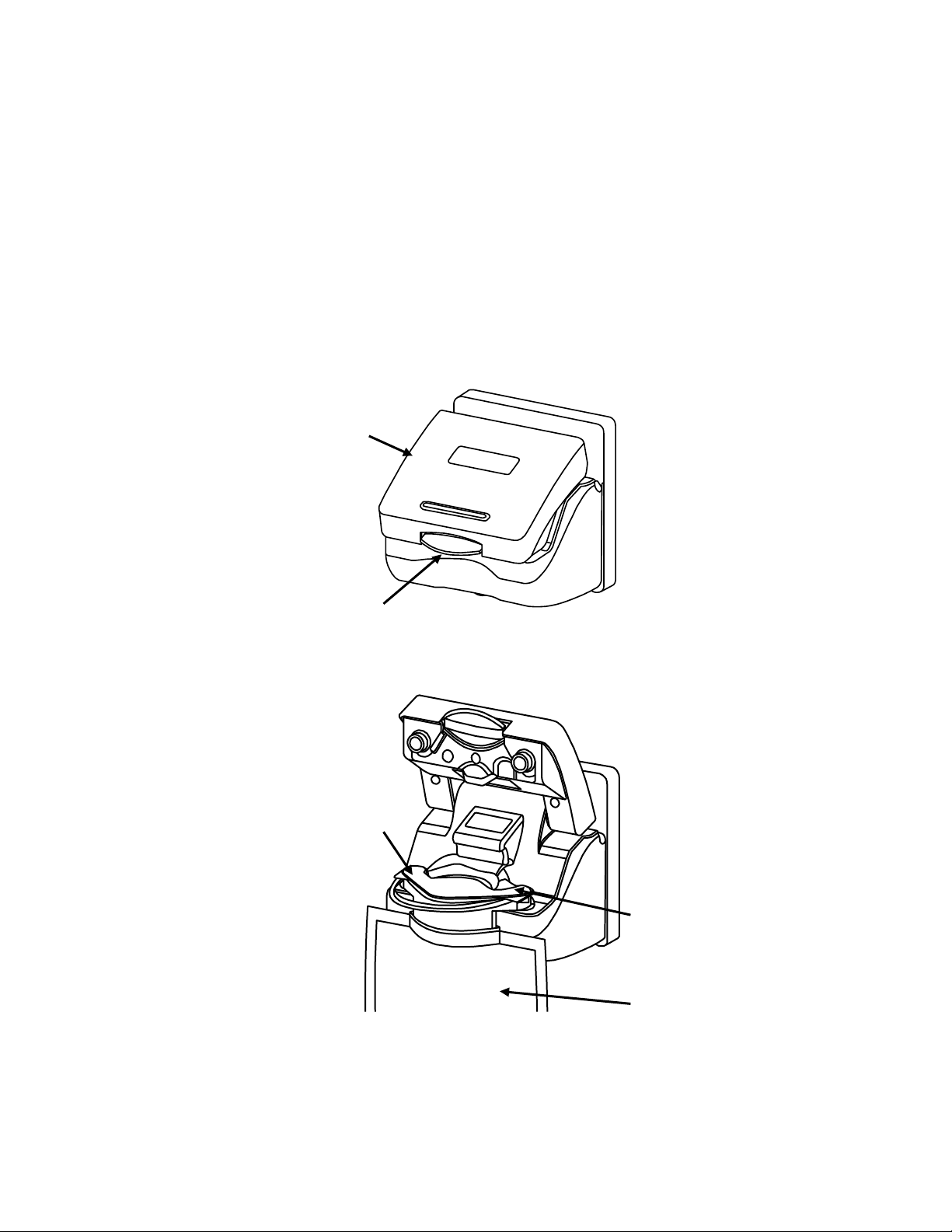
bibag door
Door handle
bibag
Bicarbonate
outlet nozzle
Water inlet
bibag Details
The bibag connector is a hardware option that allows the usage of a dry
bicarbonate powder to generate dialysate solution for the 2008®T and the
2008K@HOME™ hemodialysis machines. The bibag is a bag filled with dry
bicarbonate powder with special inlet and outlet ports. Underneath the bibag
door, the bibag hangs on two nozzles, which allow for the entry of purified
water and the exit of bicarbonate concentrate solution. A door handle locks
the bibag door in place over the bibag.
Figure 1 – bibag connector: door closed and bibag inserted with door open
Page 2
bibag V2.0 Technician’s Manual
P/N 490188 Rev. D
Page 5
Warning: The concentrate displayed on the screen must match the labels on the
acid container. Make certain there is enough concentrate in the containers to
complete the treatment.
Warning: The specific concentrate, sodium, and bicarbonate settings must be
prescribed by a physician.
Warning: Acid and basic bicarbonate hemodialysis concentrate must be diluted
(mixed with purified water as specified in the AAMI standards for water for
dialysis) immediately prior to application only.
Warning: Use aseptic technique.
Warning: Always verify the conductivity and approximate pH of the dialysate
solution through independent means before initiating dialysis. Verify that the pH
is normal and that the conductivity is reasonably close to the theoretical value. If it
is not, do not initiate dialysis.
Warning: Replace a leaking bibag immediately. Spills can cause damage to
carpeting and other surfaces. To contain such spills, the machine should be on a
spill-tolerant surface. Spills can cause slips and falls; clean up spills immediately.
Caution: Only the bags manufactured by Fresenius Medical Care may be used in
the bibag connector.
Note: When the bibag connector is installed, the online pressure holding test
becomes mandatory. For more information, see the Online Pressure Holding Test
section of the 2008®T Hemodialysis Machine Operator’s Manual P/N 490122 or
the 2008K@HOME™ Hemodialysis Machine Operator’s Manual P/N 490180.
General Warnings
bibag V2.0 Technician’s Manual
P/N 490188 Rev. D
Page 3
Page 6
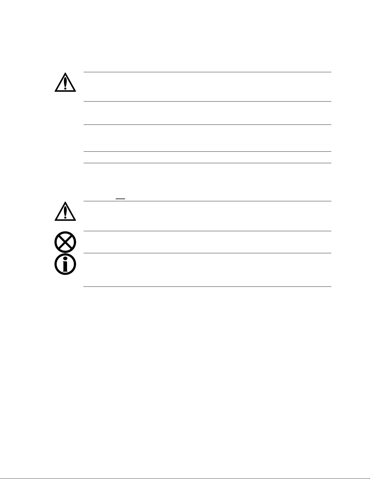
Hydraulic Flow Diagram
Page 4
Figure 2
bibag V2.0 Technician’s Manual
P/N 490188 Rev. D
Page 7

Hydraulic Component Descriptions
100 – bibag Fill Valve
The bibag fill valve opens as needed to add water to the bibag during dialysis. When the
bibag is not used for bicarbonate during dialysis, this valve will remain closed. In rinse
and cleaning modes, this valve will alternate with valve 103.
101 – bibag Vent Valve
The bibag vent valve opens momentarily during bibag dialysis when air is detected in the
bibag air separation chamber. When the bibag is not used for bicarbonate during dialysis
(jug mode), this valve will open momentarily when air is detected in the bibag air
separation chamber.
103 – Hydrochamber Outlet Valve
The hydrochamber outlet valve opens in dialysis when valve 100 is closed. In rinse and
cleaning modes, this valve will alternate with valve 100.
104 – Bicarbonate Port Valve
Closed for bibag dialysis. Opens to empty the bibag and during bibag startup. Opens
when sodium bicarbonate concentrate is supplied. When sodium bicarbonate is supplied
by a pressurized supply, this valve will open and close based on pressure at pressure
transducer 110.
105 – Acid Port Valve
Used to regulate the pressure to the acid pump. Will open and closed based upon
pressure at pressure transducer 106.
106 – Acid Port Pressure Transducer
Senses pressure of the acid concentrate supply. Pressure detected from this sensor is used
in conjunction with valve 105 to regulate the pressure to the acid concentrate pump.
108 – Rinse Port Valve
This valve is electrically in parallel with valve 104. It opens and closes at the same time
as valve 104.
110 - bibag Pressure Transducer
The bibag pressure transducer is used to measure the pressure inside the bibag. Also used to
measure the pressure of the sodium bicarbonate concentrate source when bibag is not used.
bibag V2.0 Technician’s Manual
P/N 490188 Rev. D
Page 5
Page 8

Hydraulic Component Descriptions (cont.)
111 – bibag Air Separation Chamber
The bibag air separation chamber separates air from the sodium bicarbonate concentrate
upon leaving the bibag. It also is used to separate air from the sodium bicarbonate
concentrate supplied by external sources (pre-mixed concentrates).
112 – bibag Air Separation Chamber Air Sensor
The bibag air separation chamber air sensor detects air in the air separation chamber.
113 – bibag Conductivity Cell
The bibag conductivity cell is used to measure the conductivity of the sodium bicarbonate
concentrate leaving the bibag and the conductivity of the pre-mixed concentrates.
114 – bibag Temperature Thermistor
The bibag temperature thermistor is used to measure the temperature of the bicarbonate
concentrate leaving the bibag and the pre-mixed concentrate.
115 – bibag Present Switch
The bibag present switch is built into the bibag connector. The switch is positioned so
that when a bibag is attached to the bibag connector the switch is pressed indicating the
presence of a bibag bag.
116 – Bicarbonate Temperature Thermister
Used with conductivity cell 117 to measure conductivity.
117 – Bicarbonate Conductivity Cell
Measures conductivity of the bicarbonate concentrate from the bibag after it is mixed
with R.O. water.
118 – bibag Filter
Removes any particles that may enter through the bibag.
Page 6
bibag V2.0 Technician’s Manual
P/N 490188 Rev. D
Page 9
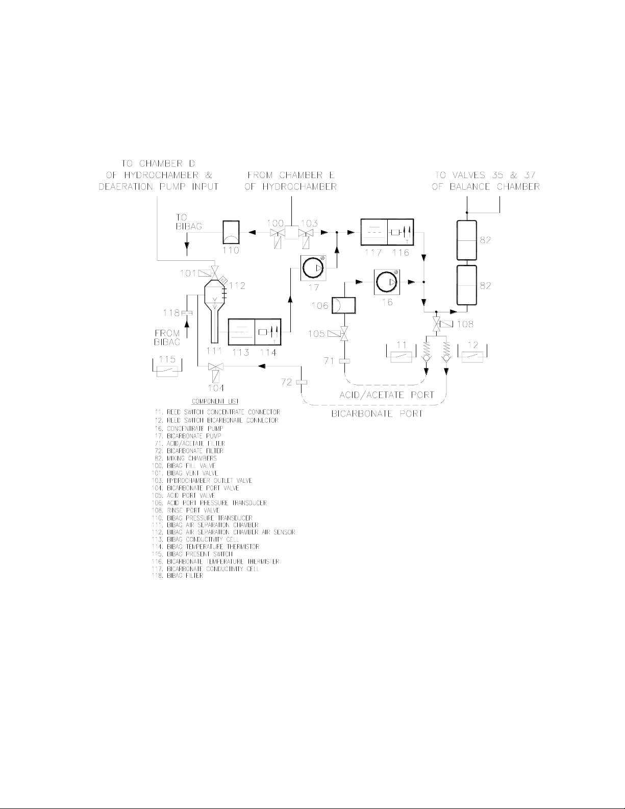
bibag Connector
3
2 4 5
bibag
1
Door
The bibag connector holds the bag with dry bicarbonate during dialysis. The bibag
connector incorporates a three position door (see Figure 3). The door may be placed in
the position open, operating, or bypass. In the open position (1) and (4), a bibag may be
installed or removed from the connector. The operating position (5) is used when a bibag
is installed for dialysis. The bypass position (3) is the completely closed position (not
possible if a bag is hanging from the connector). The door must be in the closed position
(3) for rinse, cleaning, and jug dialysis mode. Position (2) should not be used.
Figure 3
Page 7
bibag V2.0 Technician’s Manual
P/N 490188 Rev. D
Page 10

Hydraulic Operation
Dialysis with bibag
Heated water from chamber E of the hydrochamber flows to the junction of valves 100 and
103. Valve 100 opens and the bibag will start filling when the dialysate temperature at
temperature sensor 3 reaches 30 degrees C. Valve 100 will close when the pressure
reaches 150mmHg as monitored by the pressure transducer 110. After this initial fill,
valves 104 and 108 open, valve 103 closes, the balancing chamber valves open and any
excess gas generated in the bag is flushed through the hydraulics down the drain. The flow
pump runs and the machine is kept in bypass during this initial flush. Afterwards,
additional water will be added to the bag to maintain pressure in the bag of about 90mmHg.
The conductivity cell (113) and temperature sensor (114) measure the conductivity and
temperature of the sodium bicarbonate concentrate as it leaves the bag. The temperature
compensated conductivity determines the concentration of the sodium bicarbonate
concentrate and the delivery rate of the bicarbonate pump (17).
If air is sensed by the probes (112) in the air separation chamber, valve 101 is
momentarily opened to vent the air.
If the bibag pressure does not change while the bicarbonate pump is pumping, an airlock
condition is detected. To remove the airlocked condition in the bicarbonate pump, valve
100 opens to pressurize the bag to 150mmHg. Next, the flow is stopped, the balance
chamber valves are opened up, the flow pump runs, and the machine is kept in bypass.
Conductivity cell 117 checks the amount of sodium bicarbonate added to the dialysate
and an error will be displayed if the solution is not within ±5% of expected.
Dialysis with Sodium Bicarbonate Concentrates
Jug bicarbonate dialysis is also supported with the bibag hydraulics. To run in this mode,
the bibag connector door must be completely closed and the bicarbonate connector pulled
out. Valves 104 and 108 will open and close based on pressure transducer 110 to allow
bicarbonate concentrate to reach the bicarbonate pump. Conductivity and temperature of
the solution is monitored.
Rinse & Mandatory Rinse
Mandatory rinse is run after a chemical disinfect. Both rinse and mandatory rinse are the
same valve sequence for the valves in the bibag hydraulics. Valves 104 and 108 alternate
opening every 3 seconds. Valves 100 and 103 alternate opening every 3 seconds. Valve
101 is also opened periodically when conductivity is low. Valve 105 is open.
Page 8
bibag V2.0 Technician’s Manual
P/N 490188 Rev. D
Page 11

Hydraulic Operation (cont.)
Chemical Disinfection/Rinse
The same bibag valve sequence as in rinse.
Chemical Disinfection/Dwell
The same bibag valve sequence as in rinse
Acid Clean
The bibag valve sequence is the same as chemical rinse. Both concentrate and
bicarbonate connectors are plugged into acid.
Heat disinfect
The bibag valve sequence is the same as rinse.
Flow off
Valves 100 and 101 closed. Valve 103 open
bibag Empty
The bibag empty procedure removes the liquid solution from the bag to make disposal of
the used bag easier and cleaner. To empty the bag, valves 100, 103 and 105 are closed
while the balancing chamber and valves 104 and 108 are opened up. The flow pump runs
to suck solution from the bag and send it out the drain. During the emptying process, the
hydraulics are kept in bypass. When the empty is complete, the operator is notified,
normal balance chamber switching resumes, but the hydraulics remain in bypass until a
new bag is installed and correct conductivity of the dialysate returns.
bibag V2.0 Technician’s Manual
P/N 490188 Rev. D
Page 9
Page 12

Electronic Description
bibag Interface Board
The bibag interface board ‘piggybacks’ onto the actuator - test board and communicates
with it. The bibag hydraulic assembly and the bibag distribution box 2 connect
electrically to the bibag interface board with ribbon cables.
The bibag interface board contains all of the electronics required to activate the 5
additional valves, read conductivity from the bibag and bicarbonate conductivity cells,
read temperature from the bibag and bicarbonate temperature thermistor, read the status
of the bibag air sensor, and read the status of the bibag door’s internal switches. A
microcontroller on the board controls all of these processes and communicates serially
with the actuator - test board. The presence of the communications between the bibag
interface board and the actuator - test board indicates to the system the presence of the
bibag hydraulic components.
The bibag pressure transducer is automatically calibrated when the door is open, and the
value is saved into memory on the bibag interface board.
bibag Hydraulic Assembly – Distribution Board
The bibag hydraulic assembly - distribution board is a passive board that connects to the
bibag interface board through a 26 pin cable. All of the individual bibag components on
the bibag hydraulic assembly connect electrically to this distribution board.
bibag Distribution Box 2 – Distribution Board
The bibag distribution box 2 - distribution board is a passive board that connects to the
bibag interface board through a 20 pin cable. All of the individual bibag components on
the distribution box 2 connect electrically to this distribution board.
Page 10
bibag V2.0 Technician’s Manual
P/N 490188 Rev. D
Page 13

Electronic Block Diagram
bibag Connector
P/N 190598
bibag
Holder
Door
Switch
bibag
Present
Switch
(111)
bibag Conductivity
Cell
(113)
bibag Temp
Sensor
(114)
bibag Pressure
Transducer
(110)
Air Sensing
Probes
(112)
Hydrochamber
Outlet Valve
(103)
bibag Vent Valve
(101)
bibag Fill Valve
(100)
bibag Hydraulics
Distribution Board
bibag
Interface
Board (V2.0)
P/N 190861-01
Actuator-Test
Board
bibag Hydraulic Assembly
P/N 190591
bibag Distribution Box 2
Assembly P/N 190869
Acid Port
Valve (105)
Rinse Port
Valve (108)
Acid Port
Pressure Transducer
(106)
Bicarbonate
Temperature
Thermister (116)
Bicarbonate
Conductivity
Cell (117)
bibag Distribution Box 2
Distribution Board
bibag Connector
Distribution Board
Bicarbonate Port
Valve (104)
Figure 4
bibag V2.0 Technician’s Manual
P/N 490188 Rev. D
Page 11
Page 14

Mesa 90XL
Dialysate Meter
With Conductivity/Temperature Module
Mesa Serial Cable
(P/N 368402-10)
Null Modem
(P/N 190323)
Calibrations
Pressure Transducers
Power the machine on and enter Service Mode.
From the Calibrate Sensors screen, select the Pressure Transducers screen button.
On the Pressure Transducers screen, select the Regulator Pressure screen button.
1. Pull the Acid and Bicarbonate connectors and insert them halfway back into their
ports.
2. Press the [Confirm] key to set the 0 (zero) pressure calibration. The screen will
change.
When prompted, press the [Confirm] key to save the calibration. The screen will
change.
Press the [Confirm] key again to finish the calibration process.
Bicarbonate Conductivity Cell
Required Tools:
Required Supplies:
Liquid bicarbonate
Machine must be connected to an R.O. water source for this calibration.
Power the machine on and enter Service Mode.
From the Calibrate Sensors screen, select the Cond Cells screen button.
On the Cond Cells screen, select Bicarb Cell screen button.
1. Using the Null Modem, connect the Mesa Serial Cable between the 90XL
Dialysate Meter and the RS232 port on the rear of the card cage.
2. Connect the Dialysate Lines to the 90XL Conductivity/Temperature Module.
3. Select Conductivity on the 90XL.
4. Connect the acid connector to a container of R.O. water and the bicarbonate
connector to a container of sodium bicarbonate concentrate.
5. Press the [Confirm] key to start the calibration.
The screen will change and the screen will display Calibration In Progress…
During the calibration process, the 90XL will communicate with the machine
through the RS232 port.
When the calibration process is complete, the screen will display Bicarb Cond
Cell calibration is complete.
Page 12
bibag V2.0 Technician’s Manual
P/N 490188 Rev. D
Page 15

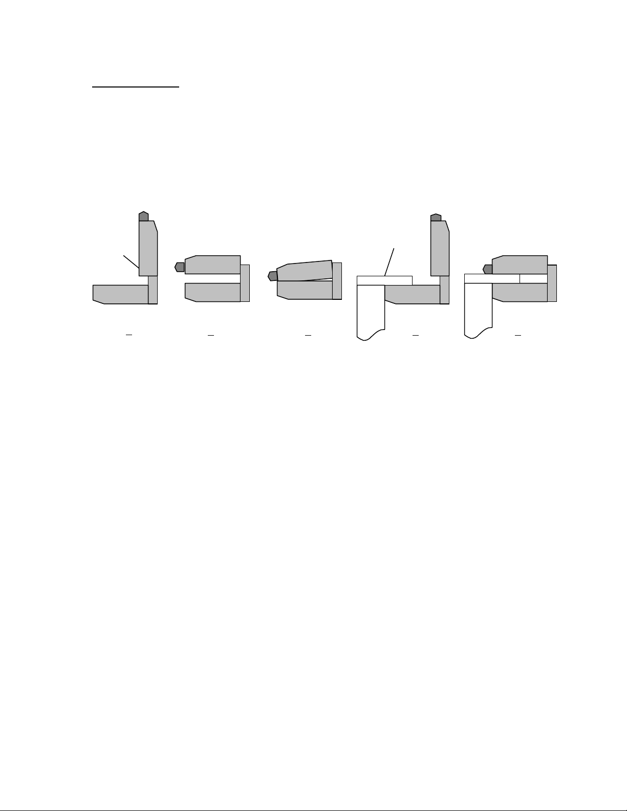
Annual Maintenance
From bibag
connector
To bibag air
separator
Note the direction of the flow
arrow on the filter housing
Annual bibag maintenance consists of the following:
Perform bibag Inlet Filter Replacement.
Perform bibag Connector Maintenance.
Perform the bibag Pressure Transducers calibration. (see page 12)
bibag Inlet Filter Replacement
Annually replace the filter (P/N M30225) in tubing assembly labeled 1 connected
between the bibag connector and the bibag air separator.
Figure 5 – bibag Inlet Filter (M30225)
bibag Connector Maintenance
Annually replace the two (2) o-rings (P/N 640919) on the bibag connector door.
Figure 6– bibag Connector Door O-Rings (640919)
Page 13
bibag V2.0 Technician’s Manual
P/N 490188 Rev. D
Page 16

Debug Screens
Debug Screen 0 – HYDRAULIC FLOW - bibag portion
D
The bibag connector is in the correct state for dialysis (i.e., it is in the Operating state).
O
The bibag connector is open (i.e., it is in the Open No bibag, Closed No bibag, or Open
with bibag present).
C
The bibag connector is closed (i.e., it is in the Bypass state).
Page 14
bibag V2.0 Technician’s Manual
P/N 490188 Rev. D
Page 17

Debug Screens (cont.)
Debug Screen 0 – HYDRAULIC FLOW - bibag portion (cont.)
100
This displays the status of the bibag fill valve. The valve opens as needed to add water to
the bibag during dialysis. When the bibag is not used for bicarbonate during dialysis, this
valve will remain closed. In rinse and cleaning modes, this valve will alternate with
valve 103. The indicator turns blue when the valve is open.
101
This displays the status of the bibag vent valve. The valve opens during bibag dialysis
when air is detected in the bibag air separation chamber. When the bibag is not used for
bicarbonate during dialysis (jug mode), this valve will open when air is detected in the
bibag air separation chamber. The indicator turns blue when the valve is open.
103
This displays the status of the hydrochamber outlet valve. The valve opens in dialysis
when valve 100 is closed. In rinse and cleaning modes, this valve will alternate with
valve 100. The indicator turns blue when the valve is open.
104
This displays the status of the bicarbonate port valve. Closed for bibag dialysis. Opens
to empty the bibag and during bibag startup. Opens when sodium bicarbonate
concentrate is supplied. When sodium bicarbonate is supplied by a pressurized supply,
this valve will open and close based on pressure at pressure transducer 110.
105
This displays the status of the acid port valve. Used to regulate the pressure to the acid
pump. Will open and closed based upon pressure at pressure transducer 106
bibag V2.0 Technician’s Manual
P/N 490188 Rev. D
Page 15
Page 18

Debug Screens (cont.)
Debug Screen 14 – bibag
Note: Debug Screen 15 on 2008K@HOME™
Open None
No bag on bibag connector, bibag door fully open.
1 =Yes / 0 = No
Operating
Bag on bibag connector, bibag door in bibag dialysis position.
1 =Yes / 0 = No
Bypass
No bag on bibag connector, bibag door fully closed.
1 =Yes / 0 = No
Cls None
No bag on bibag connector, bibag door partially closed.
1 =Yes / 0 = No
Page 16
bibag V2.0 Technician’s Manual
P/N 490188 Rev. D
Page 19

Debug Screens (cont.)
Debug Screen 14 (15) – bibag (cont.)
Opn Bag
Bag on connector, bibag door fully open.
1 =Yes / 0 = No
Bag On
Bag on bibag connector.
1 =Yes / 0 = No
D bd Ver
bibag interface board (daughter board) software version.
Init State
System is in the bibag Initial state.
1 =Yes / 0 = No
Tx State
System is in the bibag Treatment state.
1 =Yes / 0 = No
End State
System is in the bibag End state.
1 =Yes / 0 = No
Vent
System is running the bibag vent process.
1 =Yes / 0 = No
DeAirLock
System is running the bibag deairlock (air lock removal) process.
1 =Yes / 0 = No
Tm Bypass
System is running the bibag timed bypass process.
1 =Yes / 0 = No
Post Flush
System is running the bibag post empty flush process.
1 =Yes / 0 = No
bibag V2.0 Technician’s Manual
P/N 490188 Rev. D
Page 17
Page 20

Debug Screens (cont.)
Debug Screen 14 (15) – bibag (cont.)
Fill
System is running the bibag fill process (Initial state).
1 =Yes / 0 = No
Bic Pump
System requests the bicarbonate pump to be on for a bibag process.
1 =Yes / 0 = No
Bypass Ctl
System requests bypass of the dialyzer for a bibag process.
1 =Yes / 0 = No
V43 Ctl
System is suppressing the “Valve 43 Failure” error for a bibag process.
1 =Yes / 0 = No
TMP Ctl
System requests TMP control, which isolates the dialyzer and freezes dialysate pressure
for a bibag process.
1 =Yes / 0 = No
Vent En
System indicates that it is enabled to do the bibag vent process.
1 =Yes / 0 = No
Air
Air is detected by the bibag air separation chamber air sensor.
1 =Yes / 0 = No
Empty
System is running the bibag empty process.
1 =Yes / 0 = No
Emptied
System indicates that the bag is emptied.
1 =Yes / 0 = No
Page 18
bibag V2.0 Technician’s Manual
P/N 490188 Rev. D
Page 21

Debug Screens (cont.)
Debug Screen 14 (15) – bibag (cont.)
No Comm
Indicates a bibag No Communication error.
1 =Yes / 0 = No
12V Err
Indicates a bibag +12 V error.
1 =Yes / 0 = No
5V Err
Indicates a bibag +5 V error.
1 =Yes / 0 = No
-5V Err
Indicates a bibag -5 V error.
1 =Yes / 0 = No
I2C Err
Indicates a bibag I2C error.
1 =Yes / 0 = No
Door Err
Indicates a bibag Door error.
1 =Yes / 0 = No
Cond Cal
Indicates a bibag Conductivity Calibration error.
1 =Yes / 0 = No
Temp Cal
Indicates a bibag Temperature Calibration error.
1 =Yes / 0 = No
bibag V2.0 Technician’s Manual
P/N 490188 Rev. D
Page 19
Page 22

Debug Screens (cont.)
Debug Screen 14 (15) – bibag (cont.)
Pres Cal
Indicates a bibag Pressure Calibration error.
1 =Yes / 0 = No
Empty Long
Indicates a bibag Emptying Too Long error.
1 =Yes / 0 = No
Vent Long
Indicates a bibag Venting Too Long error.
1 =Yes / 0 = No
Bag Leak
Indicates a bibag Bag Leak error.
1 =Yes / 0 = No
Pres Snr
Indicates a bibag Pressure Sensor error.
1 =Yes / 0 = No
Pres Hi
Indicates a bibag Pressure Too High error.
1 =Yes / 0 = No
Pres Low
Indicates a bibag Pressure Too Low error.
1 =Yes / 0 = No
Val Comm
Indicates a bibag Valve Communication error.
1 =Yes / 0 = No
Val1 Err
Indicates a bibag Valve 1 error.
1 =Yes / 0 = No
Page 20
bibag V2.0 Technician’s Manual
P/N 490188 Rev. D
Page 23

Debug Screens (cont.)
Debug Screen 14 (15) – bibag (cont.)
Val2 Err
Indicates a bibag Valve 2 error.
1 =Yes / 0 = No
Cond High
Indicates a bibag Conductivity High error.
1 =Yes / 0 = No
Cond Low
Indicates a bibag Conductivity Low error.
1 =Yes / 0 = No
Cond Senr
Indicates a bibag Conductivity Sensor error. This bit is only set in the Rinse program.
1 =Yes / 0 = No
Temp Senr
Indicates a bibag Temperature Sensor error. This bit is only set in the Rinse program.
1 =Yes / 0 = No
Bic Lock
Indicates a bibag Bicarbonate Pump Air Locked error.
1 =Yes / 0 = No
Temperature
Displays the temperature in °C of the sodium bicarbonate concentrate from either the
bibag or a jug.
Conductivity
Displays the conductivity in mS/cm of the sodium bicarbonate concentrate from either
the bibag or a jug. This value is temperature compensated.
Pressure
Displays the bibag pressure in mmHg.
Concentration
Displays the bibag concentration in g/L during bibag dialysis.
bibag V2.0 Technician’s Manual
P/N 490188 Rev. D
Page 21
Page 24

Debug Screens (cont.)
Debug Screen 14 (15) – bibag (cont.)
JCon Low
Indicates a bicarbonate (jug) conductivity low error.
1 =Yes / 0 = No
JCon Hi
Indicates a bicarbonate (jug) conductivity high error.
1 =Yes / 0 = No
JConLowLmt
Displays the bicarbonate (jug) conductivity lower limit in mS/cm.
JConHiLmt
Displays the bicarbonate (jug) conductivity higher limit in mS/cm.
Page 22
bibag V2.0 Technician’s Manual
P/N 490188 Rev. D
Page 25

Debug Screens (cont.)
Debug Screen 15 – Bic Mon & Act. Reg
Note: Debug Screen 16 on 2008K@HOME™
Bic Low
This bit is normally set to 0, and is set to 1 when the bicarbonate conductivity (Bic Mon
Cond) has been less than “Bic Lo Th” for 40 balance chamber switches.
Bic Hi
This bit is normally set to 0, and is set to 1 when the bicarbonate conductivity (Bic Mon
Cond) has been greater than “Bic Hi Th” for 40 balance chamber switches.
Bic Cell Cond
The raw uncompensated bicarbonate conductivity being seen at the Bicarbonate
Conductivity Cell 117.
Bic Mon temp
The temperature being seen at the Bicarbonate Temperature Thermistor 116.
bibag V2.0 Technician’s Manual
P/N 490188 Rev. D
Page 23
Page 26

Debug Screens (cont.)
Debug Screen 15 (16) – Bic Mon & Act. Reg (cont.)
RO Cond
The RO water conductivity value measured at the end of rinse used to compensate “Bic
Cell Cond”.
TCB
Theoretical Conductivity of Bicarbonate based on the machines Base Na+ and
Bicarbonate settings.
Bic Lo Th
The lower threshold for compensated bicarbonate conductivity (Bic Mon Cond), 5%
below TCB.
Bic Mon Cond
The compensated bicarbonate conductivity based on Bic Cell Cond, Bic Mon temp, Bic
Slope, Bic Offset, and RO Cond.
Bic Hi Th
The upper threshold for compensated bicarbonate conductivity (Bic Mon Cond), 5%
above TCB.
Bic Slope
The slope value of the bicarbonate conductivity calculated from the bicarbonate
conductivity cell calibration.
Bic Offset
The offset value of the bicarbonate conductivity calculated from the bicarbonate
conductivity cell calibration.
Acid Press
The compensated pressure seen at the Acid Port Pressure Transducer 106.
Bic Press
The compensated pressure seen by the bibag Pressure Transducer 110 (bibag machine) or
the bicarbonate Pressure Transducer 107 (non-bibag machine).
Inlet W temp – (Not used)
Page 24
bibag V2.0 Technician’s Manual
P/N 490188 Rev. D
Page 27

Debug Screens (cont.)
Debug Screen 15 (16) – Bic Mon & Act. Reg (cont.)
PHT Err
Indicates a bibag Pressure Holding Test failure.
1 =Yes / 0 = No
AcidPr Cal Er
Indicates an Acid Pressure Calibration Error.
1 =Yes / 0 = No
InletT Cal Er – (Not Used)
BicT Cal Er
Indicates a Bicarb Temperature Calibration Error.
1 =Yes / 0 = No
V105 Er
Indicates a Valve 105 Error.
1 =Yes / 0 = No
V104 Er
Indicates a Valve 104 or Valve 108 Error.
1 =Yes / 0 = No
Reg O/S Rx
Indicates the bibag interface board has received the Regulator Pressure service mode
calibration data.
1 = Data Received / 0 = Data not Received.
V105 Er O
Indicates Valve 105 is Stuck Open.
1 =Yes / 0 = No
V105 Er C
Indicates Valve 105 is Stuck Closed.
1 =Yes / 0 = No
bibag V2.0 Technician’s Manual
P/N 490188 Rev. D
Page 25
Page 28

Debug Screens (cont.)
Debug Screen 15 (16) – Bic Mon & Act. Reg (cont.)
V104 Er O
Indicates Valve 104 or Valve 108 is Stuck Open.
1 =Yes / 0 = No
V104 Er C
Indicates Valve 104 or Valve 108 is Stuck Closed.
1 =Yes / 0 = No
Acid PresOff
The compensation value for Acid Port Pressure Transducer 106 based on the Regulator
Pressure service mode calibration.
Bic PresOff
The compensation value for bibag Pressure Transducer 110 (bibag machine) based on the
Regulator Pressure service mode calibration.
Page 26
bibag V2.0 Technician’s Manual
P/N 490188 Rev. D
Page 29

Troubleshooting
Error messages
All status messages are displayed on the control panel screen. These messages
are generated due to conditions and events that occur in the machine during
operation. These messages will reset when the condition causing the message is
corrected. In some cases, the operator must reset them.
A list of bibag -related messages can be found in the
2008®T Hemodialysis Machine bibag
Operator’s Manual P/N 508213.
2008K@HOME™ Hemodialysis Machine bibag
Operator’s Manual P/N 508340.
The list includes:
The bibag related Message
Meaning of the Message
Action Required
A full list of machine messages may be found in the
2008®T Hemodialysis Machine Operator’s Manual P/N 490122
2008K@HOME™ Hemodialysis Machine Operator’s Manual P/N 490180
bibag V2.0 Technician’s Manual
P/N 490188 Rev. D
Page 27
Page 30

2 3 5
4
1
Spare Parts
Item # Description Part Number
1. bibag connector complete 190598
2. bibag connector o-ring 640919
3. bibag connector circuit board 190547
4. Rubber tubing label “1” M42437
5. Rubber tubing label “2” M42438
Page 28
bibag V2.0 Technician’s Manual
P/N 490188 Rev. D
Page 31

10
11 7 8 4 5 3 1 6 9
2
Spare Parts (cont.)
Item # Description Part Number
bibag Hydraulic assembly 190591
Includes all shown components including items 1 through 12.
1. bibag Fill Valve (V100) 642951
2. bibag Vent Valve (V101) 674349
3. Hydrochamber Outlet Valve (V103) 642951
4. bibag Pressure Transducer (110) 190140
5. bibag Air Separation Chamber (111) 190673
with V101 and Air Sensor Probes; item 6 not included
6. bibag Air Separation Chamber Air Sensor Probe Cable 668033
7. bibag Conductivity Cell (113) M39797
8. bibag Temperature Thermistor (114) 676502
9. bibag Distribution board (inside box) 190526
10. Cable - bibag distribution board to bibag connector 190525
11. Cable - bibag distribution board to bibag interface board 190670
12. Assembly, bibag distribution 190669
Includes items 9 and 11
Page 29
bibag V2.0 Technician’s Manual
P/N 490188 Rev. D
Page 32

2 1 3 4 8
7 6 5
Spare Parts (cont.)
Item # Description Part Number
Distribution Box 2 assembly 190869
Includes all shown components including items 1 through 10.
1. Acid Port Valve (V105) 643418
2. Bicarbonate Port Valve (V104) 643418
3. Acid Port Pressure Transducer (106) 190140
4. bibag Conductivity Cell (117) M39797
5. bibag Temperature Thermistor (116) 676502
6. Cable - bibag Distribution Box 2 to bibag interface board 190865
7. Retaining Pin 330801-03
8. Distribution Box 2 only 290684
9. Distribution Box 2 cover 290685
Item not shown – cover inside item 8 and is used to retain item 10.
10. Distribution Box 2 circuit board 190860
Item not shown – board inside item 8
Page 30
bibag V2.0 Technician’s Manual
P/N 490188 Rev. D
Page 33

1 2 3
Spare Parts (cont.)
Item # Description Part Number
Valve 108 Assembly 190959
Includes all shown components including items 1 through 3.
1. Valve 108 643418
2. Bracket, Valve Single Mount 290767
3. bibag Valve 108 Cable Assembly 190958
Page 31
bibag V2.0 Technician’s Manual
P/N 490188 Rev. D
Page 34

1
2
3
4
7* 5 7*
6
Spare Parts (cont.)
Item # Description Part Number
1. Tubing 21.5” Assembly labeled 1 190877
2. Tubing 19” labeled 2 190602
3. Rubber tubing label “1” M42437
4. Rubber tubing label “2” M42438
5. Tee Connector, 3/16 674648
6. Reducer Fitting M38033
7. bibag Inlet Filter* M30225
*Note: When replacing item 7 (bibag Inlet Filter), reference the arrow on the housing for proper directional flow.
Correct flow is from the bibag connector to the bibag air separator.
Page 32
bibag V2.0 Technician’s Manual
P/N 490188 Rev. D
Page 35

Spare Parts (cont.)
bibag hydraulics
ribbon cable plugs
in here.
bibag distribution
box 2 plugs in here.
Item # Description Part Number
1. bibag Interface Board with software 190861-01
The following items are not illustrated
2 bibag V2.0 Technician’s Manual 490188
3 2008T bibag Operator’s Instructions 508213
4 2008T bibag Installation Kit 190872
5 2008T bibag V2.0 Upgrade Kit 190873
6 2008K@HOME bibag Operator’s Instructions 508340
7 2008K@HOME bibag Installation Kit 190883
8 2008K@HOME bibag V2.0 Upgrade Kit 190884
Page 33
bibag V2.0 Technician’s Manual
P/N 490188 Rev. D
Page 36

NOTES:
________________________________________________________________________
________________________________________________________________________
________________________________________________________________________
________________________________________________________________________
________________________________________________________________________
________________________________________________________________________
________________________________________________________________________
________________________________________________________________________
________________________________________________________________________
________________________________________________________________________
________________________________________________________________________
________________________________________________________________________
________________________________________________________________________
________________________________________________________________________
________________________________________________________________________
________________________________________________________________________
________________________________________________________________________
________________________________________________________________________
________________________________________________________________________
________________________________________________________________________
________________________________________________________________________
________________________________________________________________________
________________________________________________________________________
Page 34
bibag V2.0 Technician’s Manual
P/N 490188 Rev. D
Page 37

NOTES:
________________________________________________________________________
________________________________________________________________________
________________________________________________________________________
________________________________________________________________________
________________________________________________________________________
________________________________________________________________________
________________________________________________________________________
________________________________________________________________________
________________________________________________________________________
________________________________________________________________________
________________________________________________________________________
________________________________________________________________________
________________________________________________________________________
________________________________________________________________________
________________________________________________________________________
________________________________________________________________________
________________________________________________________________________
________________________________________________________________________
________________________________________________________________________
________________________________________________________________________
________________________________________________________________________
________________________________________________________________________
________________________________________________________________________
Page 35
bibag V2.0 Technician’s Manual
P/N 490188 Rev. D
Page 38

NOTES:
________________________________________________________________________
________________________________________________________________________
________________________________________________________________________
________________________________________________________________________
________________________________________________________________________
________________________________________________________________________
________________________________________________________________________
________________________________________________________________________
________________________________________________________________________
________________________________________________________________________
________________________________________________________________________
________________________________________________________________________
________________________________________________________________________
________________________________________________________________________
________________________________________________________________________
________________________________________________________________________
________________________________________________________________________
________________________________________________________________________
________________________________________________________________________
________________________________________________________________________
________________________________________________________________________
________________________________________________________________________
________________________________________________________________________
Page 36
bibag V2.0 Technician’s Manual
P/N 490188 Rev. D
Page 39

NOTES
______________________________________________________________________________
______________________________________________________________________________
______________________________________________________________________________
______________________________________________________________________________
______________________________________________________________________________
______________________________________________________________________________
______________________________________________________________________________
______________________________________________________________________________
______________________________________________________________________________
______________________________________________________________________________
______________________________________________________________________________
______________________________________________________________________________
______________________________________________________________________________
______________________________________________________________________________
______________________________________________________________________________
______________________________________________________________________________
______________________________________________________________________________
______________________________________________________________________________
______________________________________________________________________________
______________________________________________________________________________
______________________________________________________________________________
______________________________________________________________________________
______________________________________________________________________________
______________________________________________________________________________
______________________________________________________________________________
Page 40

Fresenius Medical Care North America
Manufactured by:
Fresenius USA, Inc.
4040 Nelson Avenue
Concord, CA 94520
800 227-2572
http://www.fmcna.com
 Loading...