

Page 1
TECHNICAL
APPLIX SMART
GUIDE
TECHNICAL GUIDE
NT 1021 rev A0 "simplifié"
Page 2

Page 3

NT 1021 rev A0
1 Overview ........................................................................................................... 5
1.1 General....................................................................................................5
1.2 Operation diagram .................................................................................5
1.3 Precaution for use..................................................................................6
1.4 Safety features........................................................................................ 6
1.5 Technical data ........................................................................................6
1.5.1 Electrical..................................................................................................................... 6
1.5.2 Mechanical .................................................................................................................6
1.5.3 Conformity, standards ................................................................................................ 6
2 Description and operation............................................................................... 7
2.1 Physical description of the Pump.........................................................7
2.1.1 The pump ...................................................................................................................7
2.1.2 The holder ................................................................................................................ 11
2.2 Functional description.........................................................................13
2.2.1 Subassembly of holding and control of giving set .................................................... 13
2.2.2 Pumping subassembly ............................................................................................. 13
2.2.3 Holder subassembly with external connections ....................................................... 13
3 Calibration menu ............................................................................................ 15
4 Preventive maintenance ................................................................................ 17
4.1 Recommendations ............................................................................... 17
4.2 Maintenance.......................................................................................... 17
4.3 Checks...................................................................................................19
4.3.1 Access to calibration menu ...................................................................................... 19
4.3.2 Battery temperature ................................................................................................. 20
4.3.3 Battery voltage ......................................................................................................... 21
4.3.4 Mains presence or not.............................................................................................. 21
4.3.5 Buzzer test ............................................................................................................... 22
4.3.6 Door position ............................................................................................................ 22
4.3.7 Optical clamp detection............................................................................................ 22
4.3.8 Optical background signal ........................................................................................ 23
4.3.9 Keypad .....................................................................................................................23
4.3.10 LCD .......................................................................................................................... 24
4.3.11 Nurse call relay ........................................................................................................ 24
4.3.12 Air detection .............................................................................................................24
4.3.13 Motor command test ................................................................................................ 25
4.3.14 Door alarm test......................................................................................................... 25
4.3.15 Optical detection alarm test...................................................................................... 25
4.3.16 Occlusion alarm test................................................................................................. 26
4.3.17 Air detection alarm test ............................................................................................ 26
4.3.18 Periodic control procedure ....................................................................................... 27
Applix_Smart_Gb_SimplifiéTDM.fm 3
Page 4

NT 1021 rev A0
4.4 Flow rate control.................................................................................. 29
4.4.1 Measurement with scales......................................................................................... 29
4.4.2 Measurement using a test tube................................................................................ 31
4.5 Cleaning and desinfection .................................................................. 33
4.6 Storage.................................................................................................. 33
5 Diagnosis.........................................................................................................35
5.1 Troubleshooting................................................................................... 35
5.2 Error messages.................................................................................... 37
6 Intervention procedure...................................................................................41
N°1, Procedure: Housing ........................................................................... 43
N°2, Procedure: Rechargeable batteries .................................................. 47
44 Applix_Smart_Gb_SimplifiéTDM.fm
Page 5
NT 1021 rev A0
1 Overview
1.1 General
The APPLIX Smart is intended exclusively for enteral feeding.
It can be used with both home patients and hospital patients and is a very simple pump to
operate.
The pump has a continous feeding administration programme and several functions for
patient safety.
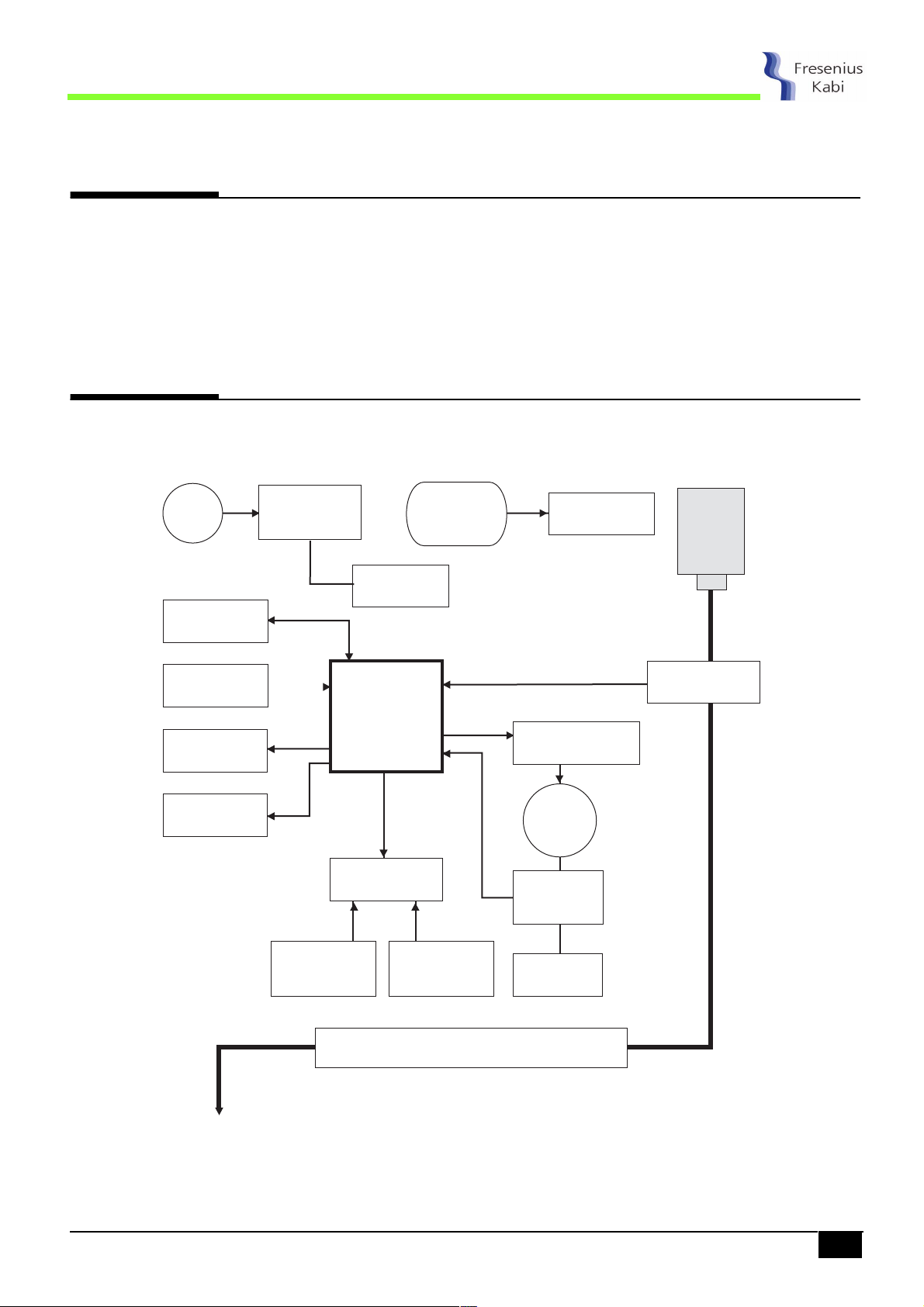
1.2 Operation diagram
230 V
Communication
Keyboard
Buzzer
Display
AC Power
suppy
Nurse call
UC
memory
watch dog
Sensor interface
Battery
and load
management
Power
regulation
Motor driving
system
Motor
gear box
Rotary or
movement
detection
Bag
Giving
set
Clamp
detection
Air in line
and
pressure sensor
Door
detection
Pumping segment
Pumping
system
applix01_01a_Gb.fm 5
Overview
Page 6

NT 1021 rev A0
1.3 Precaution for use
The manufacturer may in no case be held responsible for any medical or any other problem,
resulting from a mis-use of the equipment.
Consult the technical guide for further information.
1.4 Safety features
The device has a continuous function inspection system as soon as it is switched ON. Any
internal failure or any problem in the operating procedure is detected immediately.
Nevertheless, abnormal operation of the equipment with no obvious cause must always be
reported to the qualified person in your plant or our After Sales Service.
The Applix Pump is equipped with an internal battery which will supply power for normal
operation to the equipment if there is an electrical disturbance in the mains network.
1.5 Technical data
1.5.1 Electrical
n Mains supply: 110-230 V + 10% - 50-60 Hz.
n Pump holder output: 7.75 V - 800 mA.
n Pump battery mode: 24 h at 125 ml/h.
1.5.2 Mechanical
n Pump:
o Dimensions H x L x P: 128 x 114 x 43 mm.
o Weight: 480 g.
n Holder:
o Dimensions H x L x P: 146 x 162 x 115 mm.
o Weight: 450 g.
1.5.3 Conformity, standards
n IEC 601-1 edition 88 + amendment 1 + amendment 2.
n IEC 601-1-2 EMC.
n IEC 601-1-4 risk analysis.
n Protection against electric shock: Protection class II, symbol; type BF, symbol.
n Protection against moisture:
o Pump: IP34 (splash-protected).
o Holder: IP 31 (drip-protected).
Overview
6 applix01_01a_Gb.fm
Page 7
NT 1021 rev A0
2 Description and operation
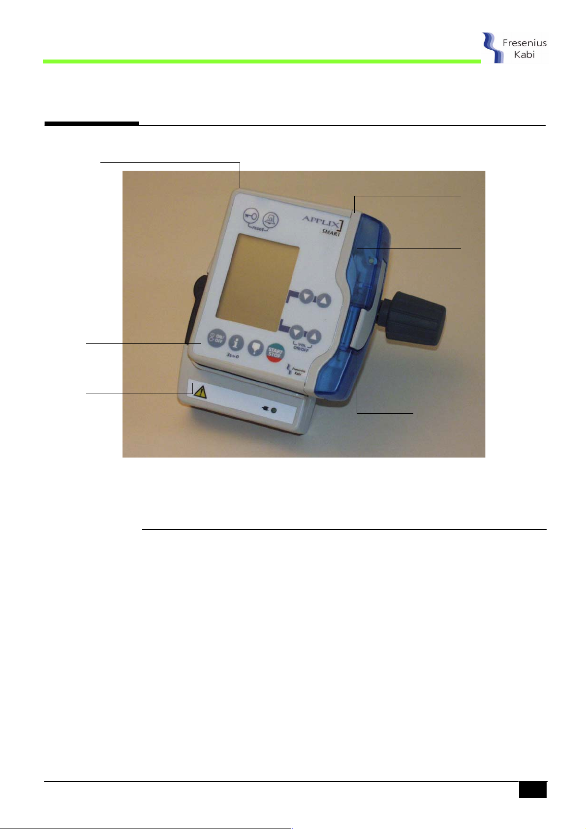
2.1 Physical description of the Pump
Housing
Keyboard
Top surface
Pump door
Holder
Door lever
The APPLIX is composed of a pump which can be mounted on a holder.
2.1.1 The pump
The Pump is composed of a top surface unit holding the mechanical and electronic assembly.
A housing fastened on the top surface unit performs mechanical protection and tightness of
equipment.
applix02_01a_Gb.fm 7
Description and operation
Page 8
NT 1021 rev A0
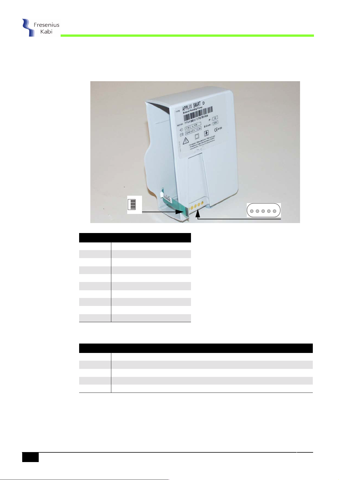
The housing is holding:
n A keyboard.
n Five contacts for connection of the pump to the holder.
The housing is connected to the different equipment by means of connectors and contacts.
Keyboard connector
to CPU board
10
1
Keyboard connector to CPU board
Pin Description
1ON/OFF
2 Column 5
3 Column 4
4 Column 3
5 Column 2
6 Column 1
7 Line 3
8 Line 2
9 Line 1
10 ON/OFF
Contacts holder/pump to CPU board
Pin Description
1 GND
2 Alarm command ouput (nurse call)
3 Output Txd
4 Input Rxd
5 Power supply
Contacts holder/pump
to CPU board
54321
Description and operation
8 applix02_01a_Gb.fm
Page 9

NT 1021 rev A0
The top surface unit is composed of:
n A CPU board.
n A pumping unit.
n A top surface.
The CPU board
The CPU board is holding the power and command electronics for the pump and the LCD
screen required for man/machine interface.
J16
J21
Optical
1 5
2 1
Motor
detection
J4
Keyboard
1 10
Air detection Holder
1 6
J17
CPU board
It is connected to the different equipment by means of connectors.
Connector J4, to keyboard
Pin Description
1ON/OFF
2 Column 5
3 Column 4
4 Column 3
5 Column 2
6 Column 1
7 Line 3
8 Line 2
9 Line 1
10 ON/OFF
Battery
J5
1 4
J6
1 5
applix02_01a_Gb.fm 9
Description and operation
Page 10

Connector J5, to battery
Pin Description
1 Battery (0 V)
2 CTN GND
3CTN (+)
4 + V Bat
Connector J6, to contacts holder
Pin Description
1GND
2 Alarm command ouput (nurse call)
3 Output Txd
4 Input Rxd
5 Power supply
Connector J16, to motor
NT 1021 rev A0
Pin Description
1 Motor 2 Motor +
Connector J17, to air detection
Pin Description
1 Transmitter (+) anode
2 Transmitter (-) cathode
3GND
4 GND
5 Receiver (+) anode
6 Receiver (-) cathode
Connector J21, to optical board clamp/points valve detection
Pin Description
1GND
2 OUT 1 (points valve)
3 OUT 2 (Clamp)
4 INPUT
5 Power supply (V_FCY)
The pumping unit
The pumping unit is fastened on the top surface. It is composed of a frame holding the
pumping mechanism, the motor driving system, the electronic board and the battery.
The top surface
The top surface is the interface between the internal and external parts of the pump.
It allows the giving set to be held in the right position and is also holding the door.
Description and operation
10 applix02_01a_Gb.fm
Page 11

NT 1021 rev A0
2.1.2 The holder
The holder is composed of a housing equipped with a clamp used to fasten it on a mast.
The holder includes a supply board which supplies 7,75 V AC mains to the APPLIX Pump. It
also performs the loading of the 1.2 Ah battery included in the pump.
It is also equipped with:
n An RJ45 (RS232) plug for connection of the nurse call relay output or the connection to a
PC.
n Five contacts for its connection to the pump :
Pin Description
1 GND
2 Alarm command ouput (nurse call)
3 Output Txd
4 Input Rxd
5 Power supply
12345
Front view of contacts
Connection of the nurse call alarm output
The nurse call alarm output can be connected by mean of a cable equipped with an RJ45
plug.
n Characteristics:
o Plug: 8-pin male RJ45.
o Length of cable: 2.5 m.
o Cable: ref. MJ8 P8C SUNS-PUlow vlt computer.
o External connection: 3 tinned wires.
n Connection:
Pin Description
1
2
3
4
5
Link with PC
678
18
6 Relay normally open
7 Common point
8 Relay normally closed
Plug male RJ45.
Note:
You can purchase this cable at:
Your Maintenance Department
(Address see enclosed)
Article number ref. 7751761.
applix02_01a_Gb.fm 11
Description and operation
Page 12

RS232 connection
n Characteristics:
o Plug: 8-pin male RJ45.
o Length of cable: 2.5 m.
o Cable: ref. MJ8 P8C SUNS-PUlow vlt computer.
o External connection: DB9 femal.
n Connection:
Pin RJ45 DB9 femal
13 TxD
2 7 RTS
34 DTR
4 2 RxD
55 GND
6
7
8
8
1
Plug male RJ45.
Note:
NT 1021 rev A0
You can purchase this cable at:
Your Maintenance Department
(Address see enclosed)
Article number ref. 200991.
Description and operation
12 applix02_01a_Gb.fm
Page 13

NT 1021 rev A0
2.2 Functional description
The APPLIX Pump is composed of three functional subassemblies:
n A subassembly of holding and control of giving set.
n A pumping subassembly.
n A holder subassembly with external connections.
2.2.1 Subassembly of holding and control of giving set
The giving set is installed on the top surface and maintained in position by the door.
The top surface is equipped with three detection systems:
n A sensor to control the closed door position (UC board).
n An optical sensor to detect the type of the installed giving set.
n An ultrasonic sensor to detect air bubbles presence in the giving set.
2.2.2 Pumping subassembly
The pumping subassembly includes the peristaltic mechanism of pumping.
This mechanism is composed of a camshaft performing the alternative travel of three
pushers. The travel of these pushers, managed by the CPU board, performs the liquid
displacement at the flow-rate.
A DC motor with a gear-box subassembly drives in rotation the camshaft by means of an
indexed belt.
An optical disc fastened at the camshaft end performs the rotation control.
The occlusion detection is carried out by the measurement of motor current.
2.2.3 Holder subassembly with external connections
The presence of the pump on the holder is detected by a sensor mounted on the holder and
associated to a magnet fastened inside the pump.
The holder is equipped with an RJ45 connector used for nurse call alarm or communication
with a PC.
applix02_01a_Gb.fm 13
Description and operation
Page 14

NT 1021 rev A0
Description and operation
14 applix02_01a_Gb.fm
Page 15

NT 1021 rev A0
3 Calibration menu
The calibration menu is used to perform tests and consult the different parameters recorded
in the pump.
The modification of these parameters can only be performed from a PC equipped with the
APPLIX control software. The software can be ordered by approved and qualified
technicians who have been trained.
For access to the different parameter readout, refer to "Control" chapter.
The calibration menu gives access to twenty-one sub-menus. Only thirteen are necessary for
the maintenance technician. Others are not detailed in this guide.
n 49
49, not detailed.
4949
n 50
50, battery temperature.
5050
n 51
51, battery voltage.
5151
n 52
52, not detailed.
5252
n 53
53, not detailed.
5353
n 54
54, not detailed.
5454
n 97
97, mains presence or not.
9797
n 98
98, buzzer.
9898
n 100
100, door position detection.
100100
n 101
101, optical clamp detection.
101101
n 102
102, not detailed.
102102
n 103
103, optical background signal.
103103
n 107
107, keypad.
107107
n 108
108, LCD.
108108
n 110
110, nurse call relay.
110110
n 112
112, not detailed.
112112
n 113
113, not detailed.
113113
n 114
114, air detection .
114114
n 119
119, motor command test.
119119
n 122
122, not detailed.
122122
applix03_01a_Gb.fm 15
Calibration menu
Page 16

NT 1021 rev A0
Calibration menu
16 applix03_01a_Gb.fm
Page 17

NT 1021 rev A0
4 Preventive maintenance
4.1 Recommendations
The APPLIX Pump can only be inspected, maintained or repaired by an approved and
qualified service. Any abnormal operation of the equipment must be signaled to the qualified
maintenance person in your plant or to our After Sales Service.
If a repair is necessary, send the pump (in its original packaging if possible) with a precise
description of the observed fault, to the official service department.
Please call our After Sales Service or our Sales Department for any information about the
repair and use of the equipment.
The manufacturer cannot be held responsible if the equipment is lost or damaged during
transport to our After Sales Service.
4.2 Maintenance
We recommand the following maintenance intervals
Periodicity Designation
12 months Carry out a periodical control.
2 years Replace the battery (refer to “battery” intervention procedure).
applix04.1&2_01a_Gb.fm 17
Preventive maintenance
Page 18

NT 1021 rev A0
Preventive maintenance
18 applix04.1&2_01a_Gb.fm
Page 19

NT 1021 rev A0
Preventive maintenance
4.3 Checks
In order to carry out a tracking of the equipment within the limits of a preventive maintenance,
a periodic control is recommended every 12 months (refer to "Periodic control procedure").
Before the control procedure, perform a preliminary loading of the battery (5 Hours).
4.3.1 Access to calibration menu
Keyboard description.
Key Function
ON/
OFF
ON/OFF, to switch on and off the equipment (to go out from the
calibration mode if pressing more than 3 seconds).
Info key, first step for accessing calibration mode.
Automatic priming, second step for accessing calibration mode.
START STOP, to start any test.
START
STOP
START
+
STOP
SET RATE, RATE for selection of calibration number.
VOL ON/OFF, for selection of any values.
VOL
ON/OFF
Activation of calibration menu.
n Press down "ON/OFF".
n Press down "INFO KEY" before the end of the down
counting and keep this position.
n When the version and checksum number appear, press
down simultaneously "AUTOMATIC PRIMING" and "START
STOP" keys, then release "INFO KEY".
CAL
CAL is displayed:
CALCAL
+
START
STOP
ON/
OFF
CAL
CAL
CALCAL
n The transition from one calibration to an other is carried out
by the "SET RATE" keys.
applix04.3_01a_Gb.fm 19
Preventive maintenance
Page 20

4.3.2 Battery temperature
NT 1021 rev A0
The battery
temperature is
displayed in
arbitary units.
n Calibration 50
o The value of the battery temperature is displayed in
arbitrary units.
o Check that this value complies with the range
0°C < T° < 60°C.
Correspondence table:
Value in arbitrary
units
3 934 0
3 773 4
3 611 8
3 450 12
3 289 16
3 127 20
2 966 24
2 804 28
2 643 32
2 482 36
2 320 40
2 159 44
1 997 48
1 836 52
1 675 56
1 513 60
50.
5050
Temperature (°C)
50
50
5050
CAL
CAL
CALCAL
2964
2964
29642964
Preventive maintenance
If the value is out of tolerances, change the battery or CPU board.
n Press "SET RATE" to carry out the next calibration.
20 applix04.3_01a_Gb.fm
Page 21

NT 1021 rev A0
4.3.3 Battery voltage
This display in
points the battery
voltage is
displayed in
arbitrary units.
n Calibration 51
o The value of the battery voltage is displayed in arbitrary
units.
o Check that this value complies with the range
0 V < U < 6 V.
Correspondence table:
Value in arbritrary
units
1 115 4,00
1 189 4,10
1 264 4,20
1 338 4,30
1 412 4,40
1 487 4,50
1 561 4,60
1 635 4,70
1 710 4,80
1 784 4,90
1 859 5,00
1 933 5,10
2 007 5,20
2 082 5,30
2 156 5,40
2 230 5,50
2 305 5,60
2 379 5,70
2 453 5,80
2 528 5,90
2600 6.00
51.
5151
Voltage (V)
51
51
5151
CAL
CAL
CALCAL
1992
1992
19921992
If the value is out of tolerance, change the battery or CPU board.
n Press "SET RATE" to carry out the next calibration.
4.3.4 Mains presence or not
This test display
the power source
mains or battery.
applix04.3_01a_Gb.fm 21
n Calibration 97
o 1111
1111, battery power supply.
11111111
o 8888
8888, mains power supply.
88888888
n Press "SET RATE" to carry out the next calibration.
97
9797
97
97
9797
CAL
CAL
CALCAL
1111
1111
11111111
Preventive maintenance
Page 22

4.3.5 Buzzer test
NT 1021 rev A0
This test enables
to test the three
sound levels of the
buzzer.
The sensor level
for the door
position is
displayed in
arbitrary units.
n Calibration 98
n Press down "START" to carry out from a level to another :
s 0
s 1
s 2
s 3
s 4
n Press "SET RATE" to carry out the next calibration.
98.
9898
0, no sound.
00
1, minimum level.
11
2, middle level.
22
3, maximum level.
33
4, maximum level.
44
4.3.6 Door position
n Calibration 100
o Close the door.
o Check that the displayed value complies with the range
2800 < U < 3800 .
o Open the door.
o Check that this value complies with the range
2000 < U < 3000 .
100.
100100
START
STOP
98
98
9898
CAL
CAL
CALCAL
100
100
100100
CAL
CAL
CALCAL
3364
3364
33643364
1111
The clamp
detection is
displayed in
arbitrary units.
If the value is out of tolerance, calibrate the sensor calibration (see 3 calibration menu).
n Press "SET RATE" to carry out the next calibration.
4.3.7 Optical clamp detection
n Calibration 101
o Without giving set.
o Check that this value complies with the range
0 < U
o Set the clamp in its housing.
o Check that this value U
U
0<U
240<U1<299 1800<U2<4000
300<U
350<U1<699 2500<U2<4000
U
101.
101101
< 700.
1
complies with the range:
2
1
<239 1500<U2<4000
1
<349 2250<U2<4000
1
>700 Error
1
U2 value
101
101
101101
CAL
CAL
CALCAL
3044
3044
30443044
If the value is out of tolerance, calibrate the optical sensor (see 3 calibration menu).
n Press "SET RATE" to carry out the next calibration.
Preventive maintenance
22 applix04.3_01a_Gb.fm
Page 23

NT 1021 rev A0
4.3.8 Optical background signal
The optical
background signal
which can disturb
the sensor
operation, is
displayed in
arbitrary units.
This test checks
the good operation
of keyboard.
n Calibration 103
o Open the door and keep empty the clamp/points valve
103.
103103
location.
o Check that this value complies with the range
0 < X < 500 .
If the value is out of tolerance, calibrate the sensor (see 3 calibration menu).
n Press "SET RATE" to carry out the next calibration.
4.3.9 Keypad
n Press down "START STOP" to start the test is display.
o Press down in sequence on the key corresponding to the
number displayed on the screen (refer to the table below).
o Pressing the "ON/OFF" key end keyboard test.
This test is incrementing one by one until the last one.
103
103
103103
CAL
CAL
CALCAL
172
172
172172
107
107
107107
CAL
CAL
CALCAL
1111
ON/
OFF
At the end of test, on "9" key, finish the test by pressing "0" key.
N° Key Description N° Key Description
1 Start/Stop 6 Up3
START
STOP
2 Lock 7 Down3
3 Loudness 8 Start/Stop
START
STOP
4 Up1 9 Fill
5 Down1 0 Info
If one key is not operating, change the housing.
n Press "SET RATE" to carry out the next calibration.
applix04.3_01a_Gb.fm 23
Preventive maintenance
Page 24

4.3.10 LCD
NT 1021 rev A0
This test enables
to control the good
operation of the
LCD.
This test enables
to control the good
operation of nurse
call relay.
n Calibration 108
o Press "START STOP" to start the test.
o Check if the LCD is functioning correctly.
o Press down "START STOP" to leave the test and carry on
the following.
If LCD is damaged, change the CPU board.
n Press "SET RATE" to carry out the next calibration.
108.
108108
4.3.11 Nurse call relay
Put the pump on the holder, with main supply.
n Calibration 110
o The relay status is displayed.
o Press down "START STOP" to drive the output:
s 0
s 1
110.
110110
0, deactivate relay.
00
1, activate relay.
11
(see connection § 2.1.2)
START
STOP
START
STOP
110
110
110110
CAL
CAL
CALCAL
0000
The signal level of
the air bubble
sensor is displayed
in arbitrary units.
nPress "SET RATE" to carry out the next calibration.
4.3.12 Air detection
n Calibration 114
o Insert the giving set full of water without bubble (door
closed):
s The measured value is displayed in arbitrary units.
s Check that this value complies with the range
o Install the giving set full of air (door closed):
s The measured value is displayed in arbitrary units.
s Check that this value complies with the range
o Remove the giving set (background):
s The measured value is displayed in arbitrary units.
s Check that this value complies with the range
s
If the value is out of tolerancces, calibrate the air bubble sensor (see 3 calibration menu)
n Press "SET RATE" to carry out the next calibration.
114.
114114
2000 < X < 4000.
0 < X < 1000.
0 < X < 1100.
114
114
114114
CAL
CAL
CALCAL
740
740
740740
Preventive maintenance
24 applix04.3_01a_Gb.fm
Page 25

NT 1021 rev A0
4.3.13 Motor command test
This test enables
to control the
motor command.
n Calibration 119
o Insert a giving set (door closed).
o Close the door.
o Press down "START STOP" to start the test.
119.
119119
Motor command
Time measurement (ms)
o Press down the "VOL" keys to select the value of the
motor command (from 0 to 100).
s The measured value is displayed in point.
s Check that this value complies with the range
300 ms.
+
Correspondence table:
Value (PWM) Time per revolution (ms)
50 1200
70 900
90 700
If the value is out of tolerances, calibrate the motor (see 3 calibration menu).
START
CAL
CAL
CALCAL
845
845
845845
VOL
ON/OFF
STOP
80
80
8080
n Press "SET RATE" to carry out the next calibration.
4.3.14 Door alarm test
To perform this test, exit test mode.
n Insert a giving set with a clamp.
n Without closing the door, press "START STOP".
o Check the presence of the door alarm.
n Close the door, press down "START STOP".
n Open the door during pumping.
o Check the presence of the door alarm.
4.3.15 Optical detection alarm test
To perform this test, exit test mode.
n Insert a giving set with a clamp.
n Close the door, press down "START STOP".
o Check the infusion start.
ON/
OFF
START
STOP
START
STOP
ON/
OFF
START
STOP
n Insert giving set alone.
n Close the door, press down "START STOP".
o Check the presence of the giving set alarm.
START
STOP
applix04.3_01a_Gb.fm 25
Preventive maintenance
Page 26

4.3.16 Occlusion alarm test
NT 1021 rev A0
To perform this test, exit test mode.
n Insert a giving set with a clamp.
n Connect a manometer to the giving set outlet.
n Close the door.
o Set the flow rate at 300 ml/h.
o Press "START STOP" to start the infusion.
o Check the presence of occlusion alarm when the pressure
is 0.7 bar < p <1.3 bar.
n Release the occlusion.
o Set a flow rate at 125 ml/h.
o Press "START STOP" to start the infusion.
o Check the presence of occlusion alarm when the pressure
is 0.7 bar < p <1.3 bar.
4.3.17 Air detection alarm test
To perform this test, exit test mode.
n Place a giving set with a clamp in the cavity of the pump.
n Close the door, set the flow rate at 300 ml/h and press
"START STOP".
n Create a small air bubble (3 cm).
o Check the absence of alarm.
n Create a big air bubble (12 cm).
o Check the presence of alarm.
ON/
OFF
START
STOP
START
STOP
ON/
OFF
START
STOP
To start again the test, select a 25 ml/h flow rate.
Preventive maintenance
26 applix04.3_01a_Gb.fm
Page 27

Preventive maintetance
NT 1021 rev A0
4.3.18 Periodic control procedure
Use this table to note the results of the different tests.
Equipment type: Code: Serial number of equipment:
N° Procedure Obtained value
1
2
3
4
5
6
7
8
9
n Check the general aspect of the pump and of the labels.
n Display the battery temperature, CAL50
o Check that 0 < T°< 60: ***************************************** ..........................
n Display the battery voltage, CAL51
n Check that 0 < U < 6: ********************************************** ..........................
n Display the supply type, CAL97
o 1111
1111, battery supply: *************************************** ..........................
11111111
o 8888
8888, mains supply: **************************************** ..........................
88888888
n Buzzer test, CAL98
n Door test, CAL100
o Open door, 2000 < U < 3000: ********************************* ..........................
o Closed door, 2800 < U < 3800: ******************************* ..........................
n Optical clamp test, CAL101
o Noise, 0 < U
o clamp in position:
. if 0 < U
. if 240 < U
. if 300 < U
. if 350 < U
. if U
n Optical background test, CAL103
o Clamp in position, 0 < U < 500: ******************************* ..........................
n Keypad test, CAL107
CAL98.
CAL98CAL98
CAL100:
CAL100CAL100
1
< 239, 1500 < U2 < 4000: **************************** ..........................
1
< 299, 1800 < U2 < 4000: ************************* ..........................
1
< 349, 2250 < U2 < 4000: ************************* ..........................
1
< 699, 2500 < U2 < 4000: ************************* ..........................
1
> 700, error: ********************************************** ..........................
1
CAL107.
CAL107CAL107
CAL97:
CAL97CAL97
CAL101:
CAL101CAL101
<700: ******************************************* ..........................
CAL103:
CAL103CAL103
CAL50:
CAL50CAL50
CAL51:
CAL51CAL51
Conformity
Yes No
10
11
12
fiche_smart.fm 27
n LCD test, CAL108
n Nurse call relay test, CAL110
o 0
0, deactivated relay: ******************************************* ..........................
00
o 1
1, activated relay: ********************************************** ..........................
11
n Air detection test, CAL114
o Without air, 2000 < U < 4000: ********************************* ..........................
o With air, 0 < U < 1000: ***************************************** ..........................
o Without giving set, 0 < U < 1100: ***************************** ..........................
CAL108.
CAL108CAL108
CAL110:
CAL110CAL110
CAL114:
CAL114CAL114
Preventive maintetance
Page 28

NT 1021 rev A0
N° Procedure Obtained value
13
14
15
16 n Occlusion alarm test:
17
18
19
20
n Motor command test, CAL119
o + 300 ms: ******************************************************* ..........................
PWM Time revolution (ms)
50 1200
70 900
90 700
n Door alarm test:
o Presence of alarm with open door when start pumping: ***** ..........................
o Presence of alarm at the opening of the door during pumping: .......................
n Optical detection alarm test:
o Infusion start if clamp: ***************************************** ..........................
o Presence alarm if only giving set: ***************************** ..........................
o Flow rate at 300 ml/h: Presence alarm if occlusion 0.7 bar < p < 1.3 bar: ......
o Flow rate at 125 ml/h: Presence alarm if occlusion 0.7 bar < p < 1.3 bar: ......
n Air bubble alarm test:
o Absence of alarm if small bubble < 3 cm: ********************* ..........................
o Presence of alarm if large bubble > 12 cm: ******************* ..........................
n Rate/battery test:
o Recharge the battery.
o Operate the pump for 10 h at a flow rate of 600 ml/h: ******** ..........................
n Flow rate test:
o +10%, 600 ml/hr: *********************************************** ..........................
n Pump + holder checking on mains:
o Connect the pump to the holder and check the mains indicator is on. .............
o Disconnect the pump and check the battery indicator is on. *..........................
CAL119:
CAL119CAL119
Conformity
Yes No
Actions:
Observations:
Name: Date: Signature:
Preventive maintetance
28 fiche_smart.fm
Page 29

NT 1021 rev A0
Preventive maintetance
4.4 Flow rate control
4.4.1 Measurement with scales
Equipment required
n Stop clock.
n Scales.
Flow rate value Scales sensitivity
5 ml/hr 1/10000th
x <
5 ml/hr < x < 30ml/hr 1/1000th
x > 30 ml/hr 1/100th
n Test tube or beaker with 1 ml graduating.
n Liquid: distilled water and oil.
n Canula:
Flow rate value Canula type
x < 30ml/hr G26
x > 30 ml/hr G18 or G21
n Giving Set: APPLIX Smart/Vision Bag Article no: 7751 711.
Installation
n According to the installation drawings shown below.
1 cm
Anti vibration measurement table
Make sure the horizontal installation plane is respected.
n Fill the container with 600 ml or more of distilled water.
n Connect a giving set with the container.
n Connect the canula with the distal end of the giving set.
n Fit the giving set on to the pump.
n Fill the giving set with water. Take care that no air is in the
tube before the measurement is started.
n Fill the test tube or the beaker with some water ensuring the
canula is dipped in the water (> 1 cm).
n Add several drops of oil to create a greasy film on the
surface of the water. This way the user will avoid any
measurement error due to evaporation of the water.
n Place the test tube or the beaker in the centre of the scales
platform.
n Place the canula inside the test tube or the beaker ensuring
that it is dipped in the water.
applix04.4_01a_Gb.fm 29
Preventive maintetance
Page 30

The giving set must not rest on the scales/test tube assembly.
Operating mode
n Select a flow rate.
n Set the scales at 00.00
n Start the pumping (if necessary make a note of the stop
clock start value).
n Press the "STOP" key to stop the test after a time interval T.
n Note the value in grams of the “infused” liquid.
n Transform the measured weight into a volume:
1 gram = 1 ml.
n Calculate the feeding rate error as follows:
Feeding rate error [%] =
measured volume [% x 60
00.00 g.
00.0000.00
[
min
T
selected feeding rate
min
h
- selected feeding rate
ml
h
NT 1021 rev A0
ml
h
x 100
30 applix04.4_01a_Gb.fm
Page 31

NT 1021 rev A0
4.4.2 Measurement using a test tube
Equipment required
n Stop clock.
n Test tube or beaker with 1 ml graduating.
n Liquid: distilled water and oil.
n Canula:
Flow rate value Canula type
x < 30ml/hr G26
x > 30 ml/hr G18 or G21
n Giving Set: APPLIX Smart/Vision Bag, Article no: 7751711.
Installation
n According to the installation drawings shown below.
1 cm
Anti vibration measurement table
Make sure the horizontal installation plane is respected.
n Fill the container with 600 ml or more of distilled water.
n Connect a giving set with the container.
n Connect the canula with the distal end of the giving set.
n Fit the giving set on to the pump.
n Fill the giving set with water. Take care that no air is in the
tube before the measurement is started.
n Fill the test tube or the beaker with some water ensuring the
canula is dipped in the water (> 1 cm).
n Add several drops of oil to create a greasy film on the
surface of the water. This way the user will avoid any
measurement error due to evaporation of the water.
n Place the canula inside the test tube on the beaker ensuring
that it is dipped in the water.
applix04.4_01a_Gb.fm 31
Page 32

Operating mode
n Select a flow rate.
n Start pumping and start the stop clock at the same time.
n After a time interval T stop the pump.
n Measure the volume that is pumped into the test tube or
beaker within the time interval T.
n Calculate the feeding rate error as follows.
Feeding rate error [%] =
min
measured volume [% x 60
[
h
- selected feeding rate
min
T
selected feeding rate
ml
h
NT 1021 rev A0
ml
h
x 100
32 applix04.4_01a_Gb.fm
Page 33

NT 1021 rev A0
Preventive maintetance
4.5 Cleaning and desinfection
The pump forms a part of the patient’s immediate environment. It is advisable to clean and
desinfect the device’s external surface on a daily basis, in order to protect patient and staff.
n Disconnect the mains cable from the wall socket before starting cleaning.
n Do not place in an AUTOCLAVE, nor IMMERGE the device, and do not allow liquids to
enter either the device’s casing, or it’s main supply cover.
o For cleaning and desinfection we recommend a previously with water diluted alcoholic
solution (ethanol < 80%).
o Avoid abrasive scrubbing which could scratch the casing.
o Neither rinse, nor wipe surfaces.
n If the equipment is used in a department with severe contamination risks, after disinfecting
by wiping with a damp cloth, equipment should be left in the room during serial desinfection.
4.6 Storage
The storage of the equipment must be done in a dry and moderated location.
The recommended environment condition for a storage of the equipment is between -20°C
and +45°C.
Relative humidity : 85% maximum without condensation.
Fully recharge the battery before using the equipment to avoid any risk caused by micro
power cuts in the mains supply and to ensure maximum autonomy.
applix04.5_01a_Gb.fm 33
Preventive maintetance
Page 34

NT 1021 rev A0
34 applix04.5_01a_Gb.fm
Page 35

NT 1021 rev A0
5 Diagnosis
5.1 Troubleshooting
Problem Cause Action
n Unjustified door alarm. n Wrong calibration. n Re-calibrate the door position.
n Sensor out of order. n Replace the door and re-
calibrate the pump.
n Unjustified optical detection
alarm.
n Unjustified occlusion alarm. n Wrong calibration. n Re-calibrate the pump.
n Unjustified air bubble alarm. n Wrong calibration. n Re-calibrate the pump.
n Damaged clamp n Replace the clamp.
n Wrong calibration. n Re-calibrate the pump.
n Out of order sensor. n Replace the top surface and
re-calibrate the pump.
n Pressure limit out of range. n Replace the pump body.
n Out of order sensor. n Replace the top surface and
re-calibrate the pump.
applix05.1_01a_Gb.fm 35
Diagnosis
Page 36

NT 1021 rev A0
Diagnosis
36 applix05.1_01a_Gb.fm
Page 37

NT 1021 rev A0
Diagnosis
5.2 Error messages
Error
code
E0
E0
E0E0
E1
E1
E1E1
E2
E2
E2E2
E3
E3
E3E3
E4
E4
E4E4
E5
E5
E5E5
E6
E6
E6E6
Description Recommanded action
n Value of A/D-converter 0 out
of range.
n Value of A/D-converter 1 out
of range.
n Value of A/D-converter 2 out
of range.
n Value of A/D-converter 3 out
of range.
n Value of A/D-converter 4 out
of range.
n Value of A/D-converter 5 out
of range.
n Value of A/D-converter 6 out
of range.
n Check air detection (see §4 air detection
"
114
114").
114114
n Check the door position (see §4 door
position "
n Check the optical detection (see §4
optical clamp detection, optical background
detection "
n Replace the CPU board.
n Replace the CPU board or the battery.
n Check battery voltage (see §4 battery
voltage "
n Replace the CPU board or the battery.
n Check battery temperature (see §4
battery temperature "
n Replace the CPU board or the battery.
100
100").
100100
101
101/103
101101
51
51").
5151
103/").
103103
50
50").
5050
E7
E7
E7E7
E8
E8
E8E8
E9
E9
E9E9
E10
E10
E10E10
E11
E11
E11E11
E12
E12
E12E12
n Value of A/D-converter 7 out
of range.
n Rotor of pump mechanism
isn't moving.
n Image of pressure has risen
too far.
n KEY_ERROR:
o Key combination stable for
too long time.
o Unused key 16 has been
evaluated (keypad disturbed).
n Current of pump motor is too
high for valid stop state ( > 10
mA, for example if motor hasn't
stopped or is running while
pumping is not active).
n US detector for air detection
is defective.
o Too high signal level
without pulse.
o Signal is higher than alarm
threshold that has been
adjusted via RS232.
n Replace the CPU board (reference
voltage).
n Check the motor command (see §4
119
commande moteur "
n Re-calibrate the pump.
n Check the keypad (see §4 keypad
107
107").
"
107107
n Check the absence of short-circuit.
n Check the motor command (see §4
commande moteur "
n Replace the CPU board.
n Check air detection (see §4 air detection
114
114").
"
114114
n Replace the top surface.
119").
119119
119
119").
119119
applix05.2_01a_Gb.fm 37
Diagnosis
Page 38

NT 1021 rev A0
Error
code
E13
E13
E13E13
E14
E14
E14E14
E15
E15
E15E15
E16
E16
E16E16
E17
E17
E17E17
E18
E18
E18E18
E19
E19
E19E19
E20
E20
E20E20
E21
E21
E21E21
Description Recommanded action
n WATCH_DOG:
Internal watchdog of controller
has attacked.
n Battery charger defective. n Replace the CPU board.
n Pump motor can not be
synchronized by light barrier
wheel.
n Watchdog of motor control
failed test.
n EEPROM defect (failed read/
write test).
n Only APPLIX Vision. n None.
n Only APPLIX Vision. n None.
n Door sensor is defective
(signal out of range).
n Giving set detection is
defective (signal too high when
both light emmitters are off).
n Write down the error adresses then
press down"ON".
n Replace the CPU board.
n Check the optical disk.
n Replace the CPU board.
n Replace the CPU board.
n Replace the CPU board.
n Check the door (see §4 door position
100
100").
"
100100
n Check the optical detection (see §4
optical clamp detection, optical background
detection "
n Replace the top surface.
n Replace the CPU board.
101
101/103
101101
103/").
103103
E22
E22
E22E22
E23
E23
E23E23
E24
E24
E24E24
E25
E25
E25E25
E26
E26
E26E26
n Motor is too slow.
o Motor needed too much
time to complete revolution
(more than 30 % longer than
it should).
o Motor had not been swit-
ched off when it had to be
switched on again in pulsed
mode.
n Motor is too fast.
o Motor has been more than
30 % faster than it should
have been.
n CRC of EEPROM not OK. n Change the CPU board.
n CRC of calibration
parameters in RAM not OK.
n A pumping has been
launched with a pump that has
not been set to calibrated state.
n Check the motor command (see §4
119
commande moteur "
n Re-calibrate the pump.
n Replace the gear motor or the pumping
unit.
n Check the motor command (see §4
commande moteur "
n Re-calibrate the pump.
n Replace the gear motor or the pumping
unit.
n Change the CPU board.
n Calibrate the pump.
119").
119119
119
119").
119119
E27
E27
E27E27
Diagnosis
38 applix05.2_01a_Gb.fm
n Measured current too low to
calculate occlusion.
n Change the CPU board.
n Check mechanical system.
Page 39

NT 1021 rev A0
Error
code
E28
E28
E28E28
Description Recommanded action
n Measured current low to
calculate occlusion.
n Change the CPU board.
n Check mechanical system.
applix05.2_01a_Gb.fm 39
Diagnosis
Page 40

NT 1021 rev A0
Diagnosis
40 applix05.2_01a_Gb.fm
Page 41

NT 1021 rev A0
6 Intervention procedure
This chapter lists all of the procedures of disassembly and reassembly.
Service shall be done by approved and qualified technicians who have been trained.
applix06.0_0001a_Gb.fm 41
Intervention procedure
Page 42

NT 1021 rev A0
Intervention procedure
42 applix06.0_0001a_Gb.fm
Page 43

Intervention procedure
NT 1021 rev A0
N°1, Procedure: Housing
Safety:
For safety reasons, the technician should not carry out any maintenace when the equipment
is voltage supplied.
Disconnect the mains power supply cable.
Required tools
n 1 Z1 Posidriv screwdriver.
n 1 flat screwdriver (small).
n 1 antistatic band.
Maintenance level
Level #2, specialised technician (refer to documentation on biomedical technical training).
Procedure
Access
n Remove the APPLIX Pump from the holder.
n Remove the label (tag #1).
n Unscrew the 3 cross-pointed screws (tag #2) located at the left of the housing; they
connect the housing to the top surface.
2
2
2
1
Do not put hands on the electronic boards (especially the LCD).
applix06.0_0010a_Gb.fm 43
Intervention procedure
Page 44

NT 1021 rev A0
Disassembly
During interventions on electronic components, it is recommended to hold a groundconnected antistatic band and to work on an antistatic foam mat.
n Gently uncouple the front face/housing assembly, bending it to prevent LCD to scrape on
the housing windows. Do not entirely remove the housing.
(During this operation, it is normal to get a resistance when separating the two parts).
n Return it on the "keyboard" face (housing to the right).
n Finish uncoupling the assembly, until seeing the white connector (tag#3).
n Disconnect the connector (tag#3)
3
Intervention procedure
44 applix06.0_0010a_Gb.fm
Page 45

NT 1021 rev A0
n Maintain the APPLIX Pump in this position and return it on the "contact" face (housing to
the left).
n Remove the housing and take care of not tearing out the keyboard flat cable (tag#4)..
4
n With a small flat screwdriver, loosen the connector (tag#5).
n Remove the flat cable, the housing is free.
5
Re-assembly
Carry out the reverse operations of disassembly taking care of correctly positioning the flat
cables and the strands.
applix06.0_0010a_Gb.fm 45
Intervention procedure
Page 46

NT 1021 rev A0
Intervention procedure
46 applix06.0_0010a_Gb.fm
Page 47

Intervention procedure
NT 1021 rev A0
N°2, Procedure: Rechargeable batteries
Safety:
For safety reasons, the technician should not carry out any maintenance when the equipment
is voltage supplied.
Disconnect the mains power supply cable.
Required tools
n 1 Z1 Posidriv screwdriver.
n 1 flat screwdriver (small).
n 1 antistatic band.
Maintenance level
Level #2, specialised technician (refer to documentation on biomedical technical training).
Procedure
Access
n Open the housing (see n°1 procedure).
Disassembly
Do not put hands on the electronic boards.
n Turn the APPLIX Pump.
n Disconnect the connector (tag#1) and remove the rechargeable battery (tag #2).
2
1
applix06.0_0020a_Gb.fm 47
Intervention procedure
Page 48

NT 1021 rev A0
For environmental protection, do not throw the batteries in the housewaste.
Remove the battery from the device prior to destruction and as during normal
maintenance replacement, return it to a competent recycling organisation.
Re-assembly
Only replace with the same model of battery recommended by the manufacturer.
Carry out the reverse operations of disassembly taking care of the correct positioning of the
flat cables and the strands.
48 applix06.0_0020a_Gb.fm
Page 49

Page 50

Useful addresses
SALES DEPARTMENT
Fresenius Kabi Nederland B.V.
Goudsboemvallei 62
5237 MK ’s-Hertogenbosch
Fresenius Kabi France
5, place du Marivel
92310 Sèvres
CUSTOMER SERVICE Tel.: 02 32 09 39 50
Tel.: 073-684 88 00
Fax: 073-648 88 48
Tel.: 01 41 14 26 00
Fax: 01 41 14 26 01
Fax: 02 32 09 39 57
Fresenius Kabi N.V.
Molenberglei 7
2627 Schelle
CUSTOMER SERVICE Tel.: 03/880.73.08
Fresenius Kabi Norge AS
Gjerdrums vei 12
0486 Olso
Fresenius Kabi AB
751 74 Uppsala
Fresenius Kabi AB
Rajatorpandie 41C
01640 Vantaa
Fresenius Kabi
Bredgade 71
1260 København K.
Fresenius Kabi Ltd.
Hampton Court, Manor Park
Rancorn, Cheshire
WA7 1UF
Fresenius Kabi Italia SpA
Via Camagre, 41
37063 Isola della Scala (VR)
Tel.: 03/880.73.02
Fax: 03/880.73.03
Fax: 03/880.73.09
Tel.: 22 58 80 00
Fax: 22 58 80 01
Tel.: 018-64 40 00
Fax: 018-64 49 20
Tel.: 09 85 20 21 05
Tel.: 33 18 16 00
Fax: 33 18 16 14
Tel.: 01928 594200
Fax: 01928 571065
Tel.: +39 045 6649 321
Fax: +39 045 6649 444
TRAINING DEPARTMENT
AFTER SALES SERVICE
Fresenius Kabi France
Le Grand Chemin, F-38590 Brézins
Fresenius Kabi N.V.
Molenberglei 7
2627 Schelle
Fresenius Kabi Ltd.
Hampton Court, Manor Park
Rancorn, Cheshire
WA7 1UF
After Sales Service Division GRENOBLE
Fresenius Vial Le Grand Chemin, 38590 Brézins
After Sales Service for UK
Pump Maintenance Departement
Fresenius Kabi Ltd.
Melbury Park, Clayton Road
Birchwood, Chesire
WA3 6FF
Tel. +33 (0)4 76 67 10 76
Fax: +33 (0)4 76 67 11 22
Tel.: 03/880.73.02
Fax: 03/880.73.03
Tel.: 01928 594200
Fax: 01928 571065
Tel.: 04 76 67 10 04
Fax: 04 76 67 11 22
Tel.: 01925 898168
This document may not be reproduced in part or in whole without the written permission of
Fresenius Kabi.
Technical Manual APPLIX Smart : NT 1021 rev A0
 Loading...