

Page 1

4008 HDF
Technical Manual
CareFresenius Medical
Page 2

4008 HDF
Technical Manual
Page 3

4008 HDF Technical Manual
The Technical Manual contains all information necessary for performing maintenance and repair work.
The 4008 HDF option reflects the latest state of technology and complies with the requirements of
EN 60601-1
Assembly, extension, adjustment, modification or repair may only be carried out by the manufacturer or
persons authorized by him.
Any inquiries should be addressed to:
Head office:
Fresenius Medical Care
Deutschland GmbH
Borkenberg 14
D-61440 Oberursel/Ts., Germany
Tel.: 06171-60-0
Telex: 410805 fres d
Fax: 06171-251-58
Local Service:
Manufacturer:
Fresenius Medical Care
Deutschland GmbH
Plant Schweinfurt
Hafenstraße 9
D-97424 Schweinfurt, Germany
Tel.: 09721-678-0
Fax: 09721-678-200
Fresenius Medical Care 4008 HDF 3/11.97 (TM) 0-1Part No. 674 398 1
Page 4

0-2 Fresenius Medical Care 4008 HDF 3/11.97 (TM)
Page 5

How to use the Technical Manual
Search and find What? Where?
Tables Contents Pages 0-5 and at the beginning of each chapter
Purpose This manual is intended for:
– first studies (to acquire basic knowledge)
– reference purposes (for start-up, maintenance and repair)
Organization The manual is divided into 6 chapters:
0 General Notes
1 Description of machine functions
2 Technical safety checks
3 Calibration instructions
4 Circuit descriptions and circuit diagrams
5 Spare parts
Numbering system Page number 1-3 is to be interpreted as: Chapter 1, Page 3
Qualification This manual is intended for service technicians
– who are familiar with the current Operating Instructions (Operating Instruc-
tionseratining to this Technical Manual are available under part no. 674 406 1)
– who have the necessary background experience in mechanics, electrical and
medical engineering
– who have been authorized by the manufacturer to perform maintenance and
repair work
– who have access to the necessary auxiliary and measuring equipment
Restrictions The study of this manual does not represent an alternative to the training courses
offered by the manufacturer.
Manual changes Manual changes will be released as new editions, supplement sheets or product
information.
Note:
Modifications relating to circuit diagrams and component layouts (SP/BP) do not
necessarily involve a change of the footer (edition).
Refer to the index field of the respective circuit diagram or component layout for
the respective state of these diagrams. The identification on the P.C.B. permits
the user/technician to verify if the circuit diagram / component layout matches the
P.C.B. actually installed.
In general, this manual is subject to modification.
Fresenius Medical Care 4008 HDF 3/11.97 (TM) 0-3
Page 6

Representation New circuit symbols are used in the circuit diagrams. Potential data given in the
circuit diagrams and setting instructions refer to the respective earth.
For example: 24 means ground for 24 V voltage.
Component marking Example:
in circuit diagrams
This refers to a resistor with a position number 75 with a resistance of 1.5 Ohm.
The decimal point is replaced by a unit symbol (to reduce the possibility of errors).
Resistors: Capacitors:
R1: 0.1 Ωµ 1: 0.1 µF
1R5: 1.5 Ω 1µ5: 1.5 µF
1K5: 1.5 kΩ 1000µ: 1000 µF
Note: When repairing or exchanging replacement parts make sure to take the applica-
ble ESD precautions (e.g. EN 100 015-1).
During repair/troubleshooting in the hydraulic unit, protect the components from
dialysate.
Technical data: The technical data for the 4008 HDF option is to be found in Chapter 1 of the
Operating Instructions.
75
1R5
0-4 Fresenius Medical Care 4008 HDF 3/11.97 (TM)
Page 7

Table of contents
Section Page
1 Description of machine functions............................................................................... 1-
1.1 Description ...................................................................................................................... 1-3
1.2 Description of extended T1 test ...................................................................................... 1-8
1.3 Error messages............................................................................................................... 1-10
2 Technical safety checks............................................................................................... 2-
3 Calibration instructions ............................................................................................... 3-
3.0 General information on the calibration instructions ....................................................... 3-3
3.1 Calibrating the UF2 pump ............................................................................................... 3-5
3.2 VDE inspections.............................................................................................................. 3-7
3.3 Calibrating the 4008 HDF scale ...................................................................................... 3-8
3.4 Calibrating the substituate sensor .................................................................................. 3-13
3.5 Calibrating the HDF blood pump .................................................................................... 3-15
3.6 Repair instructions .......................................................................................................... 3-17
4 Circuit descriptions and circuit diagrams.................................................................. 4-
4.1 LP 625 display board ...................................................................................................... 4-3
4.2 LP 754 control board HDF .............................................................................................. 4-9
4.3 LP 760 HDF motor control .............................................................................................. 4-19
4.4 LP 761 HDF drive keyboard ........................................................................................... 4-27
4.5 LP 762 scale comm ........................................................................................................ 4-33
4.6 LP 763 SSE serial interface extender............................................................................. 4-39
5 Spare parts .................................................................................................................... 5-
5.0 How to use the spare parts catalog ................................................................................ 5-3
5.1 P.C.B.s............................................................................................................................ 5-4
5.2 Scales ............................................................................................................................. 5-6
5.3 Substituate lift ................................................................................................................. 5-8
5.4 UF2 pump / blood pump (HDF) / valve V 126................................................................. 5-10
Fresenius Medical Care 4008 HDF 3/11.97 (TM) 0-5
Page 8

0-6 Fresenius Medical Care 4008 HDF 3/11.97 (TM)
Page 9

Table of contents
1 Description of machine functions
Section Page
1.1 Description .................................................................................................................... 1-3
1.1.1 Components.................................................................................................................... 1-3
1.1.2 Description ...................................................................................................................... 1-3
1.1.3 Component tests............................................................................................................. 1-3
Fig.: Block diagram ......................................................................................................... 1-4
Fig.: Flow diagram .......................................................................................................... 1-5
Fig.: Flow diagram .......................................................................................................... 1-6
1.2 Description of extended T1 test / error messages in T1 test................................... 1-8
1.2.1 Test UF-Function ............................................................................................................ 1-8
1.3 Error messages during treatment and the HDF test ................................................ 1-10
1.4 Error messages, substituate pump............................................................................. 1-13
Fresenius Medical Care 4008 HDF 3/11.97 (TM) 1-1
Page 10

1-2 Fresenius Medical Care 4008 HDF 3/11.97 (TM)
Page 11

1.1 Description
1.1.1 Components
The components of the 4008 HDF option are permanently connected to the hemodialysis
machine. The 4008 HDF option comprises the following components:
– Substituate lift
– Scales (weighing range < 20 kg) with data interface and taring facility
– Substituate pump with bidirectional data interface
– UF2 pump
1.1.2 Description
The scales determine the actual weight of the substituate reserve and signals this to the
hemodialysis machine. This calculates the substituate rate depending on the set treatment time.
A substituate sensor mounted on the substituate lift recognises whether:
– Line set is fitted without substituate or
– Line set is fitted with substituate.
The substituate pump delivers the substituate solution to the venous bubble catcher. The filtrate
from the dialysis fluid circuit is removed by the UF2 pump.
1.1.3 Component tests
The scales are checked by the operator by means of a plausibility test before treatment. The
substituate sensor is tested while the 4008 HDF is filling.
The 4008 HDF test tests:
– The substituate pump
– The UF2 pump (electrically and hydraulically)
(If the 4008 HDF test is not carried out then the connections are to be tested but once).
The UF2 pump is tested cyclically during treatment.
The electric control system of the UF2 pump is checked continuously.
Fresenius Medical Care 4008 HDF 3/11.97 (TM) 1-3
Page 12
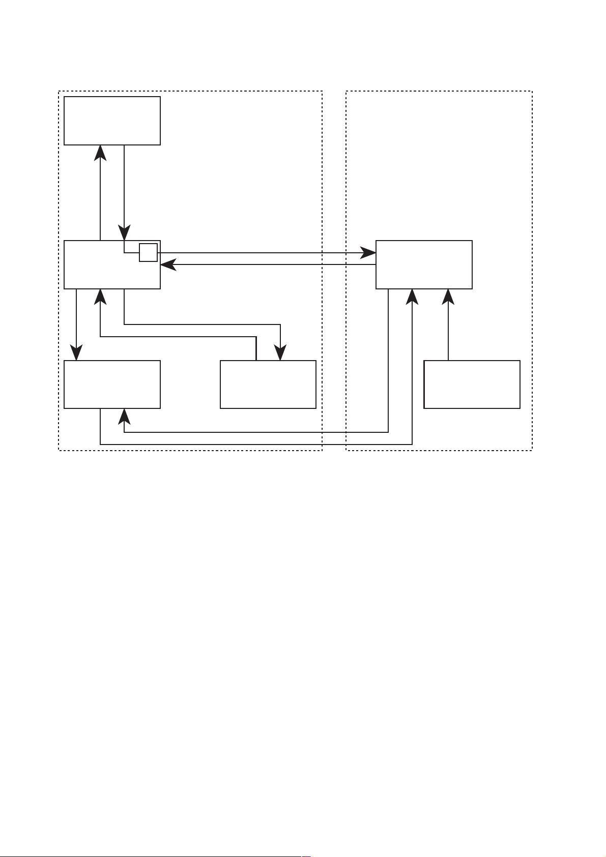
Fig.: Block diagram
Scales
Serial communication
Operating system Safety system
CPU 1
UF2 pump
W
Serial communication
Serial communication
Substituate
pump
CPU 2
TMP
1-4 Fresenius Medical Care 4008 HDF 3/11.97 (TM)
Page 13
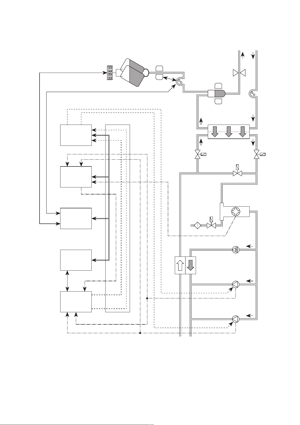
UF2
pump
UF
pump
Flow
pump
Dialysate
pressure
transducer
V126
V26
V24
V24b
Dialyzer
Air detector
Venous bubble catcher
Arterial
blood pump
Venous line
clamp
Substituate
pump
Substituate
sensor
Scales
Substituate
bag
Patient
Balancing chamber
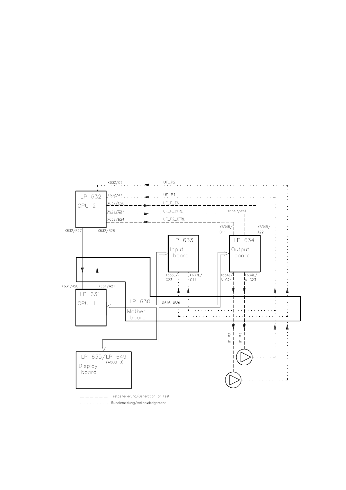
LP 632
CPU 2
LP 631
CPU 1
LP 763
SSE
Serial
interface
extender
LP 633
Input
board
LP 634
Output
board
serial
interface
X632/
B24
X632/
C27
X634 R/
C11
X634 R/
A24
serial interface
serial interface and taring line
X632/
A7
X632/
C7
X632/
A29
X634 L/
A–C24
X634 L/
A–C23
X633 L/
C14
X633 L/
C23
X633 L/
B6
Control, UF2 pump
Control, UF pump
Acknowledgement, dialysate pressure
Control, UF pump
Control, UF2 pump
Acknowledgement, UF pump
Acknowledgement, UF2 pump
Acknowledgem., dialy. pressure
XHDF 2–4
X348v/4–5
X633 R/
C28–30
Fig.: Flow diagram
Fresenius Medical Care 4008 HDF 3/11.97 (TM) 1-5
Page 14
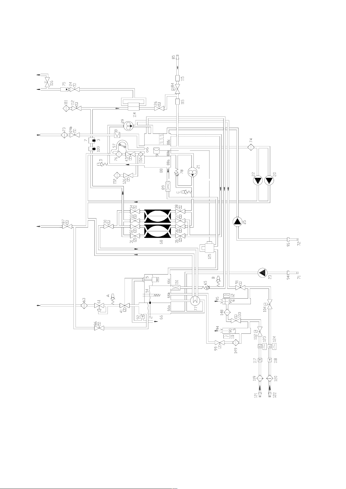
Fig.: Flow diagram
1-6 Fresenius Medical Care 4008 HDF 3/11.97 (TM)
Page 15

Legend
2 Temperature sensor
3 Temperature sensor
5 Float switch
6 Level sensor
7 Conductivity measuring cell
8 Blood leak detector
9 Pressure transducer
10 Reed contact for concentrate
12 Reed contact for bicarbonate
20 UF2 pump
21 Flow pump
22 UF pump
23 Concentrate pump
24 Dialyzer valve 1
24b Dialyzer valve 2
25 Bicarbonate pump
26 Bypass valve
29 Degassing pump
30 Drain valve
31 Balancing chamber valve 1
32 Balancing chamber valve 2
33 Balancing chamber valve 3
34 Balancing chamber valve 4
35 Balancing chamber valve 5
36 Balancing chamber valve 6
37 Balancing chamber valve 7
38 Balancing chamber valve 8
41 Water inlet valve
43 Fill valve
54 Heater rod
61 Pressure reducing valve
63 Filter/water inlet
65 Loading pressure valve
66 Heater block
66a Water inflow chamber
66b Heater rod chamber
66c Float chamber
68 Balancing chamber
71 Filter/concentrate
72 Filter/bicarbonate
73 Filter/external dialysate
74 Filter/UF
75 External flow indicator
76 Filter/fill valve
77 Heat exchanger
78 Relief valve
84 Disinfection valve
85 Disinfectant conncector
86 Recirculation valve
87 Discharge valve
88 Multifunction block
88a Degassing chamber
88b Secondary air separator
88c Primary air separator
89 Degassing orifice
90a Rinse chamber concentrate
90b Rinse chamber bicarbonate
91 Rinse valve
92 Vent valve
94 Concentrate suction tube
95 Bicarbonate suction tube
97 Ventilation pump
99 Rinse valve
100 Rinse valve
102 Concentrate valve in central delivery system
104 Bicarbonate valve in central delivery system
109 Temperature sensor
111 Hydrophobic filter
112 Vent valve
114 Dialysate filter
115 Disinfection valve sensor
116 Sampleing valve
117 Check valve (concentrate)
118 Check valve (bicarbonate)
119 Filter (concentrate)
120 Filter (bicarbonate)
121 Concentrate connector in central delivery system
122 Bicarbonate connector in central delivery system
123 Pressure switch for V 102
124 Pressure switch for V 104
125 Adapter plate
126 4008 HDF vent valve
148 Filter/rinse valve
149 Filter/rinse valve
150 Filter
151 Orifice
152 4008 HDF hydrophobic filter
Hydraulic measurement points
A Reduced water inlet pressure
B Balancing chamber loading pressure
C Flow pump pressure
D Degassing pump pressure
Fresenius Medical Care 4008 HDF 3/11.97 (TM) 1-7
Page 16
1.2 Description of extended T1 test / error messages in the T1 test
Possible error messages displayed in the T1 test are listed in the Technical Manual for the
hemodialysis machine. If the HDF option is installed and activated the following error codes can
also appear:
1.2.1 Test UF-Function
Test description:
CPU 1 starts up the UF2 pump at a defined rate.
CPU 2 controls the hydraulic and electrical function of the UF2 pump.
CPU 2 blocks the control line of the UF2 pump and checks for standstill.
UF2 counter check.
Figure:
1-8 Fresenius Medical Care 4008 HDF 3/11.97 (TM)
Page 17

Error description:
Error message Description
F11 UF-Function The interval between the strokes of the UF2 pump was less than
220 ms. Correct delivery of the required volume is not safeguarded because the stroke return travel is too short.
– A pump rate which was too high was signalled by the CPU 1.
F12 UF-Function The pulse time for the UF2 pump is less than 180 ms. Correct
delivery of the required volume is not safeguarded because the
discharge time is too short.
– Monoflop on LP 634 defect (IC 42/R65/C45).
F 13 UF-Function The pulse for the UF2 pump is longer than 500 ms. A maximum
rate of 5000 ml/h is not possible.
– Monoflop on LP 634 defect (IC 42/R65/C45).
F14 UF-Function UF2 pump not active during the test (4 s).
– Acknowledgement (UF_P2, X637/B26) → X632/C7 no LOW
pulse
– Control line (UF_P2, X634L/A–C24) → X637/B26 no LOW
pulse
F15 UF-Function The UF2 pump cannot be stopped by the CPU2.
– Control line (UF_P_EN, X632/C28) → X634R/A22 no 5 V.
– Reset input to IC 42/pin 13 on LP 634 defect.
F16 UF-Function The UF pump acknowledgement from CPU1 is faulty.
– Acknowledgement (UF_P2, X637/B26) → X633/C23 no LOW
pulse
F17 UF-Function The change in pressure after a UF2 pump stroke less than
20 mmHg.
– UF2 pump mechanically defect.
– Control line (UF_P2_CRTL, X632/B24) → X634R/C11 no
HIGH pulse.
F20 UF-Function Difference in pressure between UF pump stroke and UF2 pump
stroke more than 20 %.
– Stroke rate for UF pump or UF2 pump not set correctly.
Fresenius Medical Care 4008 HDF 3/11.97 (TM) 1-9
Page 18

1.3 Error messages during treatment and the HDF test
Message on the
display
F321 HDF-failure
F322 HDF-failure
F323 HDF-failure
Cause
The UF pump or UF2 pump
test will not be started as long
as the level sensor (6) detects
air. The level sensor (6) will
detect air one minute after the
4008 HDF test has been selected
The UF pump or UF2 pump
has carried out more than 50
strokes and still no air has
been detected.
The substituate pump runs at a
rate of 10 ml/min. to raise the
fluid level by a defined amount
in the secondary air separator
(the fluid will just be detected).
Air will still be detected after 2
minutes.
Possible error elimination
Check level sensor (6) (defect).
Check V126 (does not open,
venous bubble catcher collapses), check V43 (whether
leaking or open).
Check UF pump or UF2 pump,
respectively (mech. defect).
Check substituate tubing
(clamped off, not connected to
the venous bubble catcher).
F324 HDF-failure
F325 HDF-failure
Since fluid has been recognized in the secondary air separator the substituate pump
starts at a rate of 10 ml/min.
until a change in weight follows
on the scales (i.e. a jump in
grammes). There was no difference in weight established
after one minute.
If the expected change in
weight (i.e. a jump in
grammes) is higher or lower
than –1 g, the respective UF
pump test will be repeated.
The UF pump test was repeated more than 5 times.
Check substituate tubing
(clamped off).
Check bag (fluctuations in air
draft)
Check scales (for drifting).
1-10 Fresenius Medical Care 4008 HDF 3/11.97 (TM)
Page 19

Message on the
display
Cause
Possible error elimination
F326 UF-failure
UF1 volume-Error
or
UF2 volume-Error
F327 UF-failure
The fluid level in the secondary air separator is raised
again by the substituate pump
after 100 strokes of the UF
pump or UF2 pump, respectively, until fluid is detected.
Plus run-on time at a rate of 10
ml/min. for the gramme jump.
Air will still be detected after a
specific period of time (depending on the delivery rate of
the substituate pump).
One UF pump did not pass the
test. The filling volume for the
secondary air separator is not
within the given tolerance of
100 ml; ± 5 ml. Should the test
give a reading of over 105 ml
the cause could also be air
taken in the flow from a badly
vented dialysator.
Interval between two strokes
of the UF pump less than
220 ms.
Check substituate hose
(clamped off, not connected
with the venous bubble
catcher).
Check UF pump or UF2 pump,
respectively (not calibrated,
mechanical defect).
Check CPU 1 (defect).
F328 UF-failure
F329 UF-failure
F330 UF-failure
F331 UF-failure
F332 UF-failure
F333 UF-failure
Pulse time of a stroke of UF
pump less than 180 ml.
Pulse time of a stroke of UF
pump more than 500 ms.
Starting time for the UF pump
more than 10 seconds.
Difference between desired or
actual delivery rate of the UF
pump greater than + 10%.
UF pump stops longer than the
maximum period time.
Despite switched off ultrafiltration the change in delivery rate
of the UF pump is greater than
10 ml.
Check LP 634 (regulating
monoflop defect).
Check LP 634 (regulating
monoflop defect).
Check LP 634 (regulating end
stage defect).
Check CPU 1 / CPU 2
(communication problems).
Check LP 634 (regulating end
stage defect).
Check UF pump
(interruption, control).
Check CPU 1 / CPU 2
(communication problems)
Check CPU 1 / CPU 2
(communication problems)
F334 UF-failure
Interval between two strokes
of the UF2 pump less than
220ms.
Fresenius Medical Care 4008 HDF 3/11.97 (TM) 1-11
Check CPU 1 (defect).
Page 20

display
Cause
Possible error eliminationMessage on the
F335 UF-failure
F336 UF-failure
F337 UF-failure
F338 UF-failure
F339 UF-failure
F340 UF-failure
F341 UF-failure
Pulse time of a stroke of the
UF2 pump less than 180 ms.
Pulse time of a stroke of the
UF2 pump more than 500 ms.
Reaction time of the UF2
pump more than 10 seconds.
Difference in desired or actual
delivery rate of UF2 pump
greater than ± 10 %.
UF2 pump stops longer than
the maximum period time.
Despite switched off 4008HDF
change in delivery rate of the
UF2 pump greater than 10 ml.
Failure of UF pump.
Check LP 634 (regulating
monoflop defect).
Check LP 634 (regulating
monoflop defect).
Check LP 634 (regulating end
stage defect).
Check CPU 1 / CPU 2
(communication problems).
Check LP 634 (regulating end
stage defect).
Check UF pump (interruption,
control).
Check CPU 1 / CPU 2
(communication problems).
Check CPU 1 / CPU 2
(communication problems).
Check UF pump
(spring, screen)
F342 UF-failure
F343 UF-failure
F344 HDF-failure
F345 HDF-failure
F346 HDF-failure
F348 HDF-failure
F349 HDF-failure
Failure of UF2 pump.
Volume difference between UF
pump and UF2 pump.
Balance failure recognized by
CPU2 greater than ± 500 ml.
Bolus exceeded by more than
+ 20 ml, detected by CPU2.
CPU2 failed to perform the cyclic UF pump test within 5 minutes.
Weight change on the scales
during the weighing test greater than 2g.
The delivery rate correction
factor could still not be determined after 20 minutes treatment time.
Check UF2 pump
(spring, screen)
Check UF pump and UF2
pump (delivery volume)
Check monitor / scales
(communication problems).
Check monitor / scales
(communication problems).
Check V24B and V43 feedback lines.
Check sense of rotation of aspiration pump.
Check hydraulics unit for
leaks.
Check scales
Check substituate bag
Check substituate bag
(weight fluctuations)
Check HDF control system
(greater fluctuations)
1-12 Fresenius Medical Care 4008 HDF 3/11.97 (TM)
Page 21

1.4 Error messages, substituate pump
Code Description of failure
E.01 Line diameter outside the permitted range
E.02 Non-defined hexaswitch position
E.03 Venous pressure transducer not balanced
E.04 Failure, running time monitoring system, SN operation
E.05 SN stroke volume outside the permitted range
E.06 The SN pressure thresholds outside the value range of the AD converter
E.07 Not defined
E.08 Failure in the AD conversion
E.09 Not defined
E.10 Not defined
E.11 Not defined
E.12 Failure, speed monitoring (hall sensor)
E.13 Failure, monitoring system, current sensing resistors
E.14 Failure, monitoring system, current sensing resistors
E.15 Failure, speed monitoring system
Fresenius Medical Care 4008 HDF 3/11.97 (TM) 1-13
Page 22

1-14 Fresenius Medical Care 4008 HDF 3/11.97 (TM)
Page 23

2 T echnical safety checks
General Notes
This chapter includes all necessary technical safety checks (TSC).
These inspections must be carried out every 12 months.
The technical safety inspections stipulated for the hemodialysis machine must be carried out in addition to
these technical saftey checks.
The technical safety checks are to be recorded in the equipment log.
A technical safety checks report is to be found at the page 2-3.
Fresenius Medical Care 4008 HDF 3/11.97 (TM) 2-1
Page 24

2-2 Fresenius Medical Care 4008 HDF 3/11.97 (TM)
Page 25
Technical safety checks report Seite 1/1
Manufacturer: ............................. Date: .............................
Machine: ............................. Technician: .............................
Operating hours: .............................
Extent of checks and time limits for technical safety checks.
TIME LIMIT: every 12 months
The following checks and inspections have to be carried out on the machine at least every 12
months by persons who are capable of carrying out such technical safety checks efficiently as
a result of their training, knowledge and experience gained in practice and are not subject to
instructions as to their checking activity.
(See also BMA Bulletin dated 02.04.1987)
TSC WA No. OKDescription Desired value/function
1 UF2 pump
TSC 1.1 ❑Delivery volume (1 ml/stroke) 60 strokes = 60 ml ± 1%
2 VDE inspections (values according to EN 60601-1)
TSC 2.1 ❑Protective ground resistance max. 0.3 Ω
TSC 2.2 ❑Summarized leakage current Must fulfill both conditions:
1. No more than 1.5 times the “summari-
zed value first measured”
(“Summarized value first measured”:
Refer to the machine card enclosed with
the machine.)
2. No more than 1 mA
The technical safety checks are to be recorded in the equipment log and the results of the
checks documented.
If the machines are not safe in function and/or operation they are to be repaired or the operator
is to be informed as to the dangers involved when using the machine in its given state.
The correct completion of the listed work and the correctness of statements made are hereby
certified.
Signature, technician: Signature, customer:
..........................., date ............................. ................................ , date .............................
.................................................................... .........................................................................
Fresenius Medical Care 4008 HDF 3/11.97 (TM) 2-3
Page 26

2-4 Fresenius Medical Care 4008 HDF 3/11.97 (TM)
Page 27

Table of contents
3 Calibration instructions
Section Page
3.0 General information on the calibration instructions ................................................ 3-3
3.1 Calibrating the UF2 pump ............................................................................................ 3-5
3.2 VDE inspections............................................................................................................ 3-7
3.3 Calibrating the 4008 HDF scales ................................................................................. 3-8
3.4 Calibrating the substituate sensor.............................................................................. 3-13
3.5 Calibrating the HDF blood pump................................................................................. 3-15
3.5.1 Pressure transducer ....................................................................................................... 3-15
3.5.2 Checking SN switchover points ...................................................................................... 3-16
3.6 Repair instructions ....................................................................................................... 3-17
Fresenius Medical Care 4008 HDF 3/11.97 (TM) 3-1
Page 28

3-2 Fresenius Medical Care 4008 HDF 3/11.97 (TM)
Page 29
3.0 General information on the calibration instructions
Measuring instruments:
The same measuring instruments as used for the hemodialysis machines are to be employed.
Required in addition is a calibration weight PT6 – 5000 g.
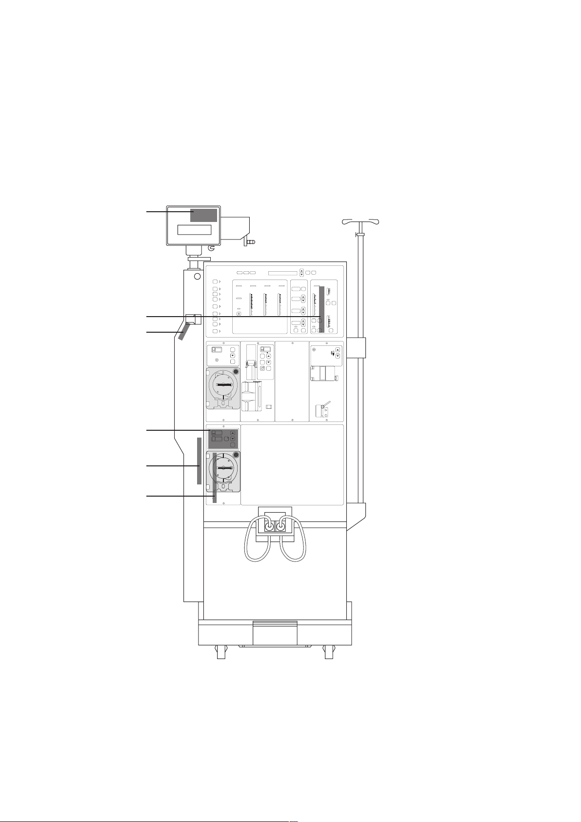
Fig.: P.C.B. overview 4008 HDF
LP 762
LP 763
LP 761
LP 625
LP 760
Fresenius Medical Care
Fresenius Medical Care
I/O
Spülen
Heißreinigen
Desinfektion
Single
Needle
Test
Vorbereiten
Dialyse Start
Alarm
Ton Aus
Rate: ml/min
(Ø: mm)
Rate: ml/min
(Ø: mm)
HDFReset
Vol : l
4008
Arterieller
Venöser
Druck
mmHgkPa mmHgkPa mmHgkPa
280
200
100
0
–100
–200
–300
Bolus
Rate
Druck
500
60
60
400
50
50
40
40
300
30
30
200
20
20
100
10
10
0
0
0
Rate: ml/h
(Bolus: ml)
( :h.min)
Start
Stop
TMP Leitfähigkeit
Luftdetektor
30
Blutleck
20
10
0
–10
–20
Überbrücken
–30
–40
Start
Stop
Start
Stop
500
400
300
200
100
0
Ultrafiltration
UF Menge
ml
Reset
UF Rate ml/h
UF Ziel ml
UF Restzeith:min
UF Variation
Prog.I/O Prog.I/O
Auswahl
Best.
Fluß
ml/min
900
700
mS/cm
(25°C)
500
300
15.5
15
14.5
SetI/O
14
13.5
Temperatur
13
°C
39
Bic.Konz.
37
35
Set
P
ven.
LP 754
Fresenius Medical Care 4008 HDF 3/11.97 (TM) 3-3
Page 30

Fig.: DIP switch 4008 HDF
ON
1 2 3 4 5 6 7 8
OFF
LP 632 CPU 2
SW1
SW 1, DIP switch 8:
ON: 4008 HDF test selectable (required/not required)
OFF: 4008 HDF test carried out automatically
3-4 Fresenius Medical Care 4008 HDF 3/11.97 (TM)
Page 31
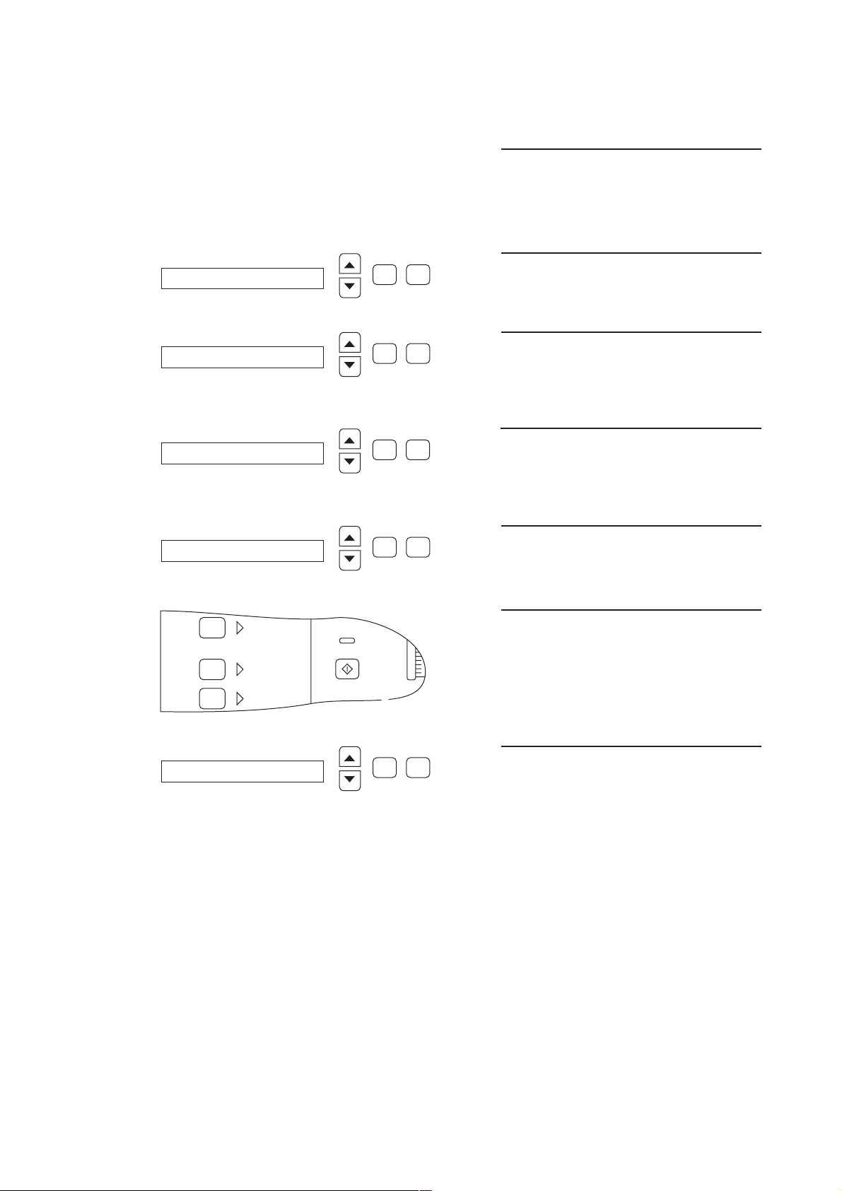
3.1 Calibrating the UF2 pump
–40
0
–10
–20
–30
Single
Needle
Test
Prime
Override
Switch off hemodialysis machine.
Set service switch to ON (top).
Switch on hemodialysis machine.
CALIBRATION
ADJ. UF-PUMP VOLUME
UF-Pump 2
pulse-amount = 60
Confirm
Confirm
Confirm
Confirm
Select
☛
Select
☛
Select
☛
Select
☛
Press the Confirm key.
Select ADJ. UF-PUMP VOLUME by
pressing the ▲ and ▼ keys.
Press the Confirm key.
Select UF-PUMP 2 by pressing the
▲ and ▼ keys.
Press the Confirm key.
Enter the number of strokes by pressing
the ▲ and ▼ keys.
Press the Override key.
ACKNOWLEDGED
☛
Select
Confirm
Fresenius Medical Care 4008 HDF 3/11.97 (TM) 3-5
Text display for approx 3 sec.
Page 32

press uf key
35
37
39
UF Variation
Prog.I/O Prog.I/O
BicConc
Set
Time Left h:min
☛
Confirm
Select
Text display
Draw off UF 2 pump line, close T-piece,
hang line in a measuring cylinder.
Press the key UF I/O.
The UF LED emits light.
The UF2 pump delivers.
uf pulses left = 59
Ultrafiltration
UF Volume ml
Reset
Volume
UF Rate ml/h
UF Goal ml
0060
Time Left h:min
UF
Prog.I/O
Confirm
Select
The remaining UF Pulses are shown in
the display.
The number of preselected pulses is
shown in the UF Goal display.
3-6 Fresenius Medical Care 4008 HDF 3/11.97 (TM)
UF-Pump 2
Confirm
Select
Text display after completion.
Check delivered quantity.
If necessary adjust UF 2 pump and repeat process.
Delivery rate: 1 ml/stroke
(60 strokes = 60 ml)
Tolerance: ± 1 %.
Page 33

3.2 VDE inspections
(Values in accordance with EN 60601-1)
.1 Protective ground resistance:
– max. 0.3 Ω.
Measuring point
Protective
ground
resistance test
.2 Summarized leakage current
Must fulfill both conditions:
1. No more than 1.5 times the “summarized value first measured”
(“Summarized value first measured”: Refer to the machine card supplied with the machine.)
2. No more than 1 mA
The measurements must be taken in the dialysis mode of operation in the “ON phase” of the
heating control system.
The scales must be travelled out to such an extent that neither of the two end switches are
actuated (middle position).
The two leakage currents are to be measured each time with different mains connection poling.
The two leakage currents are added together and give the summarized leakage current.
Fresenius Medical Care 4008 HDF 3/11.97 (TM) 3-7
Page 34

3.3 Calibrating the 4008 HDF scales
–40
0
–10
–20
–30
Single
Needle
Test
Prime
Override
☞
Note:
The prompts shown in the text display have to be run through correctly
by the technician since no direct return signal is given by the scales.
Switch off hemodialysis machine.
Set service switch to ON (top).
Switch on hemodialysis machine.
CALIBRATION
CALIB. HDF-SCALE
CHECKING HDF-SCALE!
calib. Switch ON?
Fresenius Medical Care
Confirm
Confirm
Confirm
Confirm
Select
Select
Select
Select
☛
☛
☛
Press the Confirm key.
Select CALIB. HDF-SCALE by pressing
the ▲ and ▼ keys.
Press the Confirm key.
Brief text display.
Display on scales is not illuminated.
Text display.
➀ Open housing of scales at the back.
➁ Set calibration switch for the scales in
ON position.
➁
☛
3-8 Fresenius Medical Care 4008 HDF 3/11.97 (TM)
Press the Override key.
Page 35

HDF-DISPL shows C?
–40
0
–10
–20
–30
Single
Needle
Test
Prime
Override
–40
0
–10
–20
–30
Single
Needle
Test
Prime
Override
Confirm
Select
Text display.
Fresenius Medical Care
50
0 100
C
g
HDF-SCALE unloaded ?
Confirm
☛
Select
The display on the scales is active.
A “C” appears at the top right.
Press the Override key.
Text display.
No weight is to be on the scales.
Press the Override key.
HDF-DISPL shows 0 ?
Fresenius Medical Care
50
0 100
C
g
Confirm
☛
Select
Text display.
Scales display.
Fresenius Medical Care 4008 HDF 3/11.97 (TM) 3-9
Page 36

–40
0
–10
–20
–30
Single
Needle
Test
Prime
Override
☛
–40
0
–10
–20
–30
Single
Needle
Test
Prime
Override
Press the Override key.
load 5 kg CAL. WEIGHT
Fresenius Medical Care
50
0 100
+
C
DISPL shows UNIT “g”?
Confirm
Confirm
Select
☛
Select
Text display.
Scales display: 5000 g
Hang calibration weight PT6 – 5000 g on
scales.
Press the Override key.
Text display.
Fresenius Medical Care
50
0 100
+
3-10 Fresenius Medical Care 4008 HDF 3/11.97 (TM)
g
Scales display: 5000 g.
Page 37

–40
0
–10
–20
–30
Single
Needle
Test
Prime
Override
☛
–40
0
–10
–20
–30
Single
Needle
Test
Prime
Override
–40
0
–10
–20
–30
Single
Needle
Test
Prime
Override
Press the Override key.
calib. Switch OFF ?
Fresenius Medical Care
50
0 100
+
g
HDF-SCALE unloaded ?
Confirm
➀
Confirm
Select
☛
Select
Text display.
➀ Set calibration switch for the scales to
OFF position.
➁ Close housing.
Press the Override key.
Text display.
Remove calibration weight.
SCALE CALIBRAT. done
CALIB. HDF-SCALE
Press the Override key.
☛
Select
Confirm
Select
Confirm
Fresenius Medical Care 4008 HDF 3/11.97 (TM) 3-11
Brief text display.
Text display.
Page 38

Switch off hemodialysis machine.
Set service switch to OFF (bottom).
Switch on hemodialysis machine.
Hang calibration weight PT6 – 5000 g on
scales.
Fresenius Medical Care
0 100
+
Scales display: 5000 g
50
g
Remove calibration weight.
Calibration of 4008 HDF scales
completed.
3-12 Fresenius Medical Care 4008 HDF 3/11.97 (TM)
Page 39

3.4 Calibrating the substituate sensor
I/O
Spülen
Heißreinigen
Desinfektion
Single
Needle
Test
Vorbereiten
Dialyse Start
Alarm
Ton Aus
Bes
Luftdetektor
Arterieller
Druck
Venöser
Druck
TMP
Blutleck
Überbrücken
Ultrafiltration
Reset
UF Menge
UF
Prog.I/O
mmHgkPa mmHgkPa mmHgkPa
ml
UF Rate ml/h
UF Ziel ml
UF Restzeith:min
4008
Rate: ml/min
(Ø: mm)
Rate: ml/h
(Bolus: ml)
Bolus
( :h.min)
–40
0
–100
–200
–300
100
200
280
0
10
20
30
–10
–20
–30
0
100
200
0
10
20
30
300
400
500
40
50
60
0
100
200
0
10
20
30
300
400
500
40
50
60
Fresenius Medical Care
XHDF
XWAAGE
X348V_SN
P1
IC14
X348V
IC17
IC2
D26
IC8
TP
I/O
Spülen
Heißreinigen
Desinfektion
Single
Needle
Test
Vorbereiten
Dialyse Start
Alarm
Ton Aus
Bes
Luftdetektor
Arterieller
Druck
Venöser
Druck
TMP
Blutleck
Überbrücken
Ultrafiltration
Reset
UF Menge
UF
Prog.I/O
mmHgkPa mmHgkPa mmHgkPa
ml
UF Rate ml/h
UF Ziel ml
UF Restzeith:min
4008
Rate: ml/min
(Ø: mm)
Rate: ml/h
(Bolus: ml)
Bolus
( :h.min)
–40
0
–100
–200
–300
100
200
280
0
10
20
30
–10
–20
–30
0
100
200
0
10
20
30
300
400
500
40
50
60
0
100
200
0
10
20
30
300
400
500
40
50
60
Fresenius Medical Care
0
1
F
2
E
3
D
4
C
5
B
6
A
7
9
8
Place filled substituate line in substituate sensor.
Set potentiometer P1 on the LP 754 so
that the LED D26 just illuminates.
Place empty substituate line in substituate sensor.
Fresenius Medical Care 4008 HDF 3/11.97 (TM) 3-13
Page 40

Adjust potentiometer P1 on LP 754 until
XHDF
XWAAGE
X348V_SN
P1
IC14
X348V
IC17
IC2
D26
IC8
TP
XHDF
XWAAGE
X348V_SN
P1
IC14
X348V
IC17
IC2
D26
IC8
TP
LED D26 just turns off.
Count the number of revolutions the
potentiometer is turned. Keep this
0
1
F
2
E
3
D
4
C
5
B
6
A
7
9
8
number in your mind.
Turn back the potentiometer P1 on the
LP 754 by half this number.
The LED D26 will illuminate again.
0
1
F
2
E
3
D
4
C
5
B
6
A
7
9
8
3-14 Fresenius Medical Care 4008 HDF 3/11.97 (TM)
Page 41

3.5 Calibrating the HDF blood pump
Start
Stop
Rate: ml/min
(Ø: mm)
HDFReset
Vol : l
Start
Stop
Rate: ml/min
(Ø: mm)
HDFReset
Vol : l
3.5.1 Pressure transducer
E
D
C
B
X348V_SN XHDF
0
1
F
2
3
4
5
6
A
7
9
8
Switch the hemodialysis machine off.
Set HEX switch on the LP 754 to
position “F”.
Switch the hemodialysis machine on.
XWAAGE
Display 000
Open SN pressure transducer to atmos-
phere.
Press the Start/Stop key.
☛
Display 250
Apply a pressure of 250 mmHg to the SN
pressure transducer.
Press the Start/Stop key.
☛
Fresenius Medical Care 4008 HDF 3/11.97 (TM) 3-15
Page 42
Start
Stop
Rate: ml/min
(Ø: mm)
HDFReset
Vol : l
Display – – –
0
1
F
2
E
3
D
4
C
5
B
6
A
7
9
8
Switch off hemodialysis machine.
Set HEX switch on the LP 754 to
position 1.
Balancing out has been completed.
XWAAGE
X348V_SN
XHDF
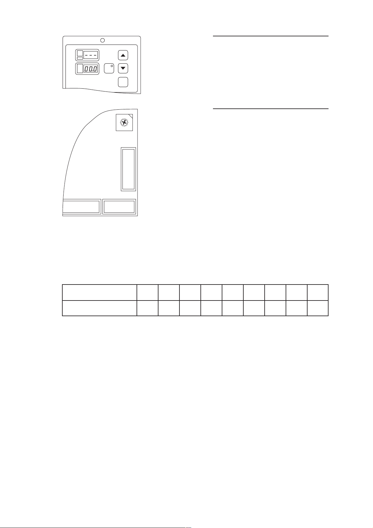
3.5.2 Checking SN switchover points
Bottom switchover point: fixed at 75 mmHg (± 6 mmHg)
Top switchover points (± 6 mmHg):
Stroke volumes (ml) 10 15 20 25 30 35 40 45 50
Top switchover point 110 130 150 172 195 219 244 270 299
3-16 Fresenius Medical Care 4008 HDF 3/11.97 (TM)
Page 43

3.6 Repair instructions
Important:
If the substituate lift has to be dismounted for repair the seal is to be
checked and if necessary renewed
before fitting the lift again.
Drip water protection!
Fresenius Medical Care 4008 HDF 3/11.97 (TM) 3-17
Page 44

3-18 Fresenius Medical Care 4008 HDF 3/11.97 (TM)
Page 45

Table of contents
4 Circuit descriptions and circuit diagrams
Section Page
Fig.: Connection diagram 4008 HDF .............................................................................. 4-3
Fig.: Wiring diagram 4008 HDF ...................................................................................... 4-5
Fig.: Block circuit diagram, mains voltage 4008 HDF.................................................... 4-7
Fig.: Block circuit diagram, low voltage 4008 HDF ........................................................ 4-7
4.1 LP 625 display board .................................................................................................... 4-9
4.1.1 Description ...................................................................................................................... 4-9
4.1.2 Circuit and component layout diagram ........................................................................... 4-11
4.2 LP 754 control board HDF............................................................................................ 4-15
4.2.1 Description ...................................................................................................................... 4-15
4.2.2 Circuit and component layout diagram ........................................................................... 4-17
4.3 LP 760 HDF motor control............................................................................................ 4-23
4.3.1 Description ...................................................................................................................... 4-23
4.3.2 Circuit and component layout diagram ........................................................................... 4-25
4.4 LP 761 HDF drive keyboard ......................................................................................... 4-29
4.4.1 Description ...................................................................................................................... 4-29
4.4.2 Circuit and component layout diagram ........................................................................... 4-31
4.5 LP 762 scales comm..................................................................................................... 4-35
4.5.1 Description ...................................................................................................................... 4-35
4.5.2 Circuit and component layout diagram ........................................................................... 4-37
4.6 LP 763 serial interface extender .................................................................................. 4-41
4.6.1 Description ...................................................................................................................... 4-41
4.6.2 Circuit and component layout diagram ........................................................................... 4-43
Fresenius Medical Care 4008 HDF 3/11.97 (TM) 4-1
Page 46

4-2 Fresenius Medical Care 4008 HDF 3/11.97 (TM)
Page 47

Fig.: Connection diagram 4008 HDF
LP 639
power logic
(4008 / 4008 E)
LP 744
power control 1
(4008 B)
X639B
(X744A
X744C)
LP 754
control board
HDF
Rate: ml/min
(Ø: mm)
HDFReset
Vol : l
Start
Stop
SN
Substituate
pump
XWAAGE
X348v
XHDF
X348v
Motor
Substituate lift
Auxiliary socket
LP 762
scales
comm
X4
M
LP 761
HDF drive
keyboard
X5X4
X2X1
Switch
Substituate lift
X3
Module
Scales
Module
Scales
X1
Substituate
sensor
X2
LP 760
X2
HDF motor
control
X1
X3
XHDF
X637B
X637C
LP 763
SEE serial interface
extender
X63Z
X637B
X637C
XA1P
XA4V0
UF2 pump
LP 747 distribution board
V126
LP 630
motherboard
Fresenius Medical Care 4008 HDF 3/11.97 (TM) 4-3
Page 48

4-4 Fresenius Medical Care 4008 HDF 3/11.97 (TM)
Page 49

Fig.: Wiring diagram 4008 HDF
LP 639
power logic
(4008 / 4008 E)
LP 744
power control 1
(4008 B)
LP 754
control board HDF
X348v XHDF
123456789
1011121314151617181920
X744A/1
X744C/3
123456789
M
N1
L1
2
3
X639B
4
N23
PE4
LP 760
control
X1
N3
LC4
PE1
PE2
X5
+12V1
UP2
STOP3
DOWN4
SE15
9
SE26
SE37
SE48
no assignment
no assignment10
X2
8
L11
L12
1
2
3
4
5
6
7
8
9
X4
HDF motor
X3
1234567
24V1
SE12
AGND (SE2)3
SE34
SE45
WRXD6
WTXD7
TARA8
no assignment9
XWAAGE
no assignment10
no assignment11
no assignment12
MOTOR_CTRL13
10
10
11
12
13
14
PWR_GND14
Substituate sensor
SUB_A1
SUB_K2
1
2
3
4
LP 761
5
6
X2
7
8
9
10
drive
keyboard
SUB_C3
X1
HDF
PWR_GND4
no assignment5
no assignment6
SN2
TXD4
RXD5
BSST1
BPST3
SNST11
ADKS7
BPR_VEN10
BPSB_VEN6
BPUS_VEN8
no assignment9
no assignment12
no assignment13
X348v XHDF
motherboard
X63Z
A1
C1
A28
A29
A31
A32
C28
C29
C31
C32
C20
C21
+5VA32
+5VC32
+24VA29
+24VC29
+12VA31
PWR_GNDA28
PWR_GNDC28
X63Z
interface extender
+12VC31
RXD_EXT_1C20
LP 763
SEE serial
TXD_EXT_1C21
DGNDA1
DGNDC1
VEN_BPR_SET14
+12V16
AGND15
LP 630
24V19
24V20
WTXD2
WRXD3
PWR_GND17
HDF_ON1
PWR_GND18
X637B X637C
UF_P226–28 26–28
X637B X637C
distribution
XA1P XA4V0
UF_P2 10
UF2 pump V 126
TARA4
BL_AL5
LP 747
board
+12V9
AGND10
HDF_LOG26
HDF_LOG17
no assignment8
V12614 14
V126 9
+12V1
X2
1
+12V
AGND2
2
END_SW
Switch substituate lift
RXD4
TARA3
X1
LP 762
scales
comm
–8
TXD5
+12V7
END_SW6
no assignment1
no assignment2
no assignment3
no assignment5
no assignment8
X3
no assignment12
no assignment13
no assignment14
X4
no assignment6
1
2
3
GND4
4
5
TXD6
6
7
GND7
8
9
GND9
10
PRINT10
11
TARA11
12
13
14
W1IW21
1
F22
2
F13
3
4
CF4
5
ON/OFF5
6
Module
scales
Fresenius Medical Care 4008 HDF 3/11.97 (TM) 4-5
Page 50

4-6 Fresenius Medical Care 4008 HDF 3/11.97 (TM)
Page 51

Fig.: Block circuit diagram, mains voltage 4008 HDF
Main
trans-
former
T 2,5 A T 2,5 A
Mains
relay
T 2,5 A
Mains
plug
Mains
filter
Mains
switch
(on back
of machine)
511 K 1 µF T 2,5 A
Fig.: Block circuit diagram, low voltage 4008 HDF
Standby-
trans-
former
Auxiliary
socket
Motor relay
Direction of turn
switchover
M
Main
transformer
24 V
switch controller
I
≈ 15 A
max
(short circuit
cut-out)
12 V
switch controller
I
≈ 4 A
max
(current
limitation)
LP 633
input board
LP 630
motherboard
LP 634
output board
LP 754
control board
HDF
LP 761
HDF drive
keyboard
+12 V
LP 760
HDF motor control
Linear controller
+24 V +12 V
current restricted
internally to
approx. 1 A
Scales
+12 V
Fresenius Medical Care 4008 HDF 3/11.97 (TM) 4-7
Page 52

4-8 Fresenius Medical Care 4008 HDF 3/11.97 (TM)
Page 53

4.1 LP 625 display board
4.1.1 Description
● General
The displays and the keyboard are on this P.C.B..
Plug connections to LP 625:
– X189, connection to LP 760
● Display
All necessary information is given to the user through 6 multiplex 7-segment displays and 2 LEDs
which are mounted on the socket.
● Keyboard
The keyboard comprises 3 single non-illuminated keys and 1 key with integrated LED (HDF). The
keys are soldered directly to the P.C.B..
The user receives a acknowledgement through a spring contact when the keys are pressed.
Fresenius Medical Care 4008 HDF 3/11.97 (TM) 4-9
Page 54

4-10 Fresenius Medical Care 4008 HDF 3/11.97 (TM)
Page 55

4.1.2 Circuit and component layout diagram
A
B
C
D
E
F F
E
D
C
B
AENDERUNG NAME
NAME
AUS
TAG ERSATZ
ERSATZ FORMAT
BE
GE
NO
TAG
12345678
1234
5
BLATT
0
1
2
3
4
5
6
7
8
9
10
11
12
13
14
15
16
17
18
19
20
MEDIZIN-
TECHN.
SYSTEME
SP
DISPLAY BOARD
1(1)
673872
1992
ST
LP625
30.06.
24.11. D.KOE
a
neue Zeichnung
19.02.93
Asch.
Asch.b
R86(R13)best. 12.03.93
c
SH5,IC1 neu 12.07.94
AN
AN
a
g
b
e
c
d
f
DP
AN
AN
a
g
b
e
c
d
f
DP
AN
AN
a
g
b
e
c
d
f
DP
AN
AN
a
g
b
e
c
d
f
DP
AN
AN
a
g
b
e
c
d
f
DP
AN
AN
a
g
b
e
c
d
f
DP
A8
A7
A6
A5
A4
A3
A2
A1 Y1
Y2
Y3
Y4
Y5
Y6
Y7
Y8
G2
G1
&
EN
GND
+5V
+24V
X
+24V
+24V
+5V
+5V
+5V
+5V
+5V+5V+5V+5V +5V
1
2
3
4
5
6
10
9
8
7
DP1
HDSP7801
1
2
3
4
5
6
10
9
8
7
DP2
HDSP7801
1
2
3
4
5
6
10
9
8
7
DP3
HDSP7801
1
2
3
4
5
6
10
9
8
7
DP4
HDSP7801
1
2
3
4
5
6
10
9
8
7
DP5
HDSP7801
1
2
3
4
5
6
10
9
8
7
DP6
HDSP7801
1
19
2
3
4
5
6
7
8
9
18
17
16
15
14
13
12
11
IC1
74HCT541
8
7
6
5
4
3
2
1
LD1
HLMP2655
12
LD2
HLMP2400
34
LD2
HLMP2400
R3
4K99
R1
4K99
R6
7K50
R5
7K50
R4
7K50
R9
7K50
R8
7K50
R7
7K50
R2
4K99
R10
4K99
R11
121R
1
2
3
4
5
6
7
8
16
15
14
13
12
11
10
9
RN1
8X220R
R12
150R
R13
4K99
12
SH1
RF15
12
SH2
RF15
12
SH3
RF15
21
SH4
MTG
SH5
RF15
T8
BS170
T3
BC327-40
T1
BC327-40
T6
BC327-40
T4
BC327-40
T2
BC327-40
T7
BC547B
T5
BC327-40
1
X189
10
X189
11
X189
12
X189
13
X189
14
X189
15
X189
16
X189
17
X189
18
X189
19
X189
2
X189
20
X189
21
X189
22
X189
23
X189
24
X189
25
X189
26
X189
3
X189
4
X189
5
X189
6
X189
7
X189
8
X189
9
X189
LP 625 display board
LP 625
Circuit diagram
Fresenius Medical Care 4008 HDF 3/11.97 (TM) 4-11
Page 56

4-12 Fresenius Medical Care 4008 HDF 3/11.97 (TM)
Page 57

LP 625
Component layout diagram
Fresenius Medical Care 4008 HDF 3/11.97 (TM) 4-13
Page 58

4-14 Fresenius Medical Care 4008 HDF 3/11.97 (TM)
Page 59

4.2 LP 754 control board HDF
4.2.1 Description
● General
The control, section and power pack are on the this P.C.B..
Plug connections to LP 754:
– X186, connection to position sensor
– X188, connection to stepper motor
– X189, connection to LP 748
– X190, connection to cover switch
– X192, connection to pressure transducer
– X348, connection to dialysis monitor
Hexswitches on the LP 754:
0 No function
1 Single needle blood pump / 4008 HDF / ON LINE HDF
2 – A No function
B Blood pump stop alarm (15, 30 secs.)
C No function
D Call-up operating time meter (display x 100 = number of hours)
E Test operation (only manufacturer)
F Pressure transducer calibration
● Voltage generation
The +24 V and +12 V voltage supply is made available to the blood pump by the monitor. The +5
V supply voltage is generated on the module by the switch controller IC 20 from the +24 V voltage
to minimize loss of power.
● Stepper motor control
The stepper motor is run in microstep operation to reduce noise. The resolution is 60 microsteps
per step. The RISC processor transmits a 8-bit dataword alternately on the pins 3 and 5 of the DA
converter from IC 7. Two sine form voltages are available on the output of the converter, phase
offset by 90°. They are conducted to the stepper motor controller IC 2 together with the current
direction signals. Together with the two SM drivers IC 1/IC 22 and the current sensor resistors
R58/R59 as feedback these form a closed control circuit which determine two sine-shaped
currents, phase offset by 90°, in the two coils.
Fresenius Medical Care 4008 HDF 3/11.97 (TM) 4-15
Page 60

● Microprocessor
The cycle frequency of the microprocessor is determined by the quartz Q2 between the processor
connections 39 and 40. Quartz oscillation is made possible by the capacitors C5 and C6.
The keyboard signals and the signals BSST, BPST are read-in through the port P4.
The IC 9 serves as intermediate memory for the addresses AO/A7.
The ALE signal on pin 50 of the microprocessor is the control line of the data address latch.
The signal from the revolution and direction of turn sensor (position sensor) in the pump bed is
read-in through port T1.
The operation data of the pump is saved in the NOVRAM IC 21 through ports 5.1 to 5.3 when the
dialysis machine is switched off or there is a voltage failure. Undervoltage detection (power down)
is through the comparitor IC 23.
With the WR line the data takeover for the display is controlled in the external data latch IC 14.
● PLL intermediate circuit
PLL component IC 4 together with the counter IC 19 causes the frequency coming from the
processor to control the stepper motor to be multiplied otherwise the processor would be too slow
to generate this frequency.
● RISC processor
The RISC processor IC 5 is supplied with a cycle signal from the processor. With each cycle an
8-bit data word is read from a look up table by the processor alternately for each phase of the
stepper motor, respectively. Included in this data word is both the current direction as well as the
current desired value.
A watchdog for the CPU is also incorporated in the RISC processor. When a cycle is missing on
pin 8/IC 5 the RISC processor triggers a reset by the CPU through pin 7.
● Display control
The data word for controlling the display is stored in IC 14. The multiplex operation of the
individual digits is made possible through the decoder IC 18.
● Speed and flow
The speed is transmitted by the processor through port P 1.1 and the flow through port P 1.2 to
the dialysis monitor.
● Pressure measurement
The differential measurement amplifier for the pressure transducer is formed by the IC 6 (1/2/3)
and IC 6 (5/6/7). The measuring signal is read-in by the processor through the AD converter input
AN 7 and calibrated for zero and steepness by the software. Afterwards the measuring signal is
modulated to pulse width through port P1.3 and transmitted through a subsequent DA converter
IC 11 (5/6/7) to the monitor.
4-16 Fresenius Medical Care 4008 HDF 3/11.97 (TM)
Page 61

4.2.2 Circuit and component layout diagram
LP 754 control board HDF
LP 754
Circuit diagram 1/2
Fresenius Medical Care 4008 HDF 3/11.97 (TM) 4-17
Page 62

4-18 Fresenius Medical Care 4008 HDF 3/11.97 (TM)
Page 63

LP 754
Circuit diagram 2/2
Fresenius Medical Care 4008 HDF 3/11.97 (TM) 4-19
Page 64

4-20 Fresenius Medical Care 4008 HDF 3/11.97 (TM)
Page 65

LP 754
Component layout diagram
Fresenius Medical Care 4008 HDF 3/11.97 (TM) 4-21
Page 66

4-22 Fresenius Medical Care 4008 HDF 3/11.97 (TM)
Page 67

4.3 LP 760 HDF motor control
4.3.1 Description
● General
The LP 760 serves to control the lift drive.
Lift operation presupposes that the scales are swung away. This is recognized by a limit switch.
The scales can be moved upwards or downwards by pressing the ▲ or ▼ keys. The drive is
switched off automatically, likewise by limit switches, when reaching the uppermost or bottommost position. When the scales are being travelled upwards or downwards they can be stopped
at any time with the Stop key.
The motor for the lift drive is safeguarded against overloading by means of an integrated
thermoswitch. If this protection facility responds the lift will come to a standstill. The lift can be
used again after the motor has cooled down.
● Circuit structure
Supply voltage
The control circuit is supplied with +12 V. This voltage is generated from the +24 V voltage of the
hemodialysis machine by the linear controller T1 in conjunction with the capacitors C4, C5 and
C6.
Motor control
Two types of circuit are implemented to control the motor:
a) continuous operation (R21 with components, R22 without components
b) inching operation for downwards movement (R21 without components, R22 with
components).
To Point a):
One D flip-flop is available for each direction of movement (IC 3). The flip-flops are set by a high
level on X2/2 (key ▲) or X2/4 (key ▼). The flip-flop for the respective other direction of movement
is reset at the same time by pressing the appropriate key. The two flip-flops are reset through high
level on X2/3 (Stop key). This also takes place should the head of the scales be swung over the
machine (high level on X1/6).
To Point b):
There is only one flip-flop available for the upwards movement (IC 3/pin 1/2). The flip-flop for the
downward movement is set through IC 5. The control logic for the downward operation is not
influenced by this (see Point a). However, the drive is only active as long as the key ▼ is pressed.
The IC 5 works as an 8 to 1 multiplexer. The address (0 to 7) of the input to be interconnected is
provided through the pins 11 to 13. Only the address 3 leads to a low level on output IC 5/14 and,
as a result, to the motor starting. R 20 serves as a pull-up resistor. A defined output level is
obtained with the IC 5/14 in high ohmic state, caused by pressing the Stop key (high level on IC
5/15).
Fresenius Medical Care 4008 HDF 3/11.97 (TM) 4-23
Page 68

● Other circuit sections
The motor feed lines are circuited through the relay RL 1 and RL 2. The position of RL 1
determines the travel direction of the lift. The motor is switched on and off through RL 2. Both
relays are controlled by the transistors T 2 (RL 1) and T 3 (RL 2). T 2 is controlled directly from the
non-inverted output IC 3/1. The output signals of both flip-flops, IC 3/2 and IC 3/12 (inverted) are
used to control T 3 and are linked with each other through IC 1/1 and IC 1/2. In the case of low
level on one of the two flip-flop outputs IC 3/2 or IC 3/13 (i.e. the respective flip-flop has been set)
the IC 1/pin 3 links up high level and T 3 switches RL 2.
● Motor current recognition
The motor current is monitored while the lift is operating. The internal thermal-protective switch
responds in the case of the motor becoming overheated. Both flip-flops (IC 3) are reset by motor
current recognition so that the motor does not start up again automatically after the drive has
cooled down. The voltage drop is evaluated through the high load resistor R 18 for motor current
recognition. The generated alternate voltage caused by the current flow through R 18 is
connected to the capacitor C 14 and C 13 through the diodes D 4 and D 5. The resulting direct
voltage through R 13 is approx. double so high as the peak value of a half wave of the alternate
voltage on R 18 less the on state voltages of D 4 and D 5. The direct voltage controls the
optocoupler IC 4 through R 14. R 13 serves to completely discharge C 13 and C 14 when the
motor is switched off.
IC 4 ensures protective isolation of the control circuit from the mains voltage conducting
components of the current recognition system.
The output of the optocoupler is circuited with the pull-up resistor R 19 against 12 V. High level on
the collector of IC 4 resets both flip-flops through IC 1/pin 12 and 13 and IC 1/8. This would lead
to continuous blocking of the control circuit unless further measures were taken. This is why the
output of IC 4 is connected up parallel to a further transistor T 4. In switched off state the capacitor
C 12 is charged through high level on IC 1/4 through D 3 and R 10. This makes the transistor T 4
conductive. After setting one of the flip-flops (IC 3) the IC 1/4 goes to low. C 12 discharges itself
through R 11, R 12 and the B-E path from T 4. T 4 blocks after approx. 500 ms. The output
transistor must be linked by IC 4 before this time has elapsed otherwise both flip-flops will be reset
again.
4-24 Fresenius Medical Care 4008 HDF 3/11.97 (TM)
Page 69

4.3.2 Circuit and component layout diagram
A
B
C
D
E
F
G
12345678910
B
C
D
E
F
G
H
12345
H
BLATT
NAMTAGAUS
BE
GE
NO
AENDERUNG
TAG NAME
ERSATZ ERSATZ FORMAT
0
1
2
3
4
5
6
7
8
9
10
11
12
13
14
15
16
17
18
19
20
MEDIZIN-
TECHN.
SYSTEME
A3
1994
1(1)
SP
673 720 LP760
21.09. OTT
C1-C3 STUETZKONDENSATOREN
HDF-MOTOR-STEUERUNG
HDF-MOTOR-CONTROL
(1)
(2)
(3)
T100mA
*
*
R22 NICHT BESTUECKT / NOT FITTED
M
a
X1.1war +24V
>1_
>1_
I
AD
O
1D
S
R
C1
1D
S
R
C1
X7
X6
X5
X4
X3
X2
X1
X0
C
B
A
Z
INH
EN
+24V
AGNDAGND AGND
+12V
AGND
UP
STOP
AGND
DOWN
AGND
+12V
AGND
AGND
+12V
AGND
END_SW
AGND
AGND
SE1
SE2
SE3
SE4
+12V
+12V
SE1
SE2
SE3
SE4
+24V
RXD
+24V
AGND
AGND
+24V
AGND AGND
+24V
L1
L1
N2
PE
PE
N
LC
TXD
TARA
MOTOR_CTRL
AGND
AGND
TARA
RXD
TXD
+12V
+12V
AGND
+12V +12V
AGND
+12V
+12V
AGND AGND
AGNDAGND
PE
+12V
AGND
R5
73K2
2
3
4
5
1
IC2
4072
9
10
11
12
13
IC2
4072
1
2
3
T1
7812
C5
100N
C4
10U
C6
1U0
6
5
3
4
1
2
IC3
4013
8
9
11
10
13
12
IC3
4013
R2
10K0
R3
10K0
R4
10K0
2
X2
3
X2
4
X2
C7
10U
C8
1N0
C10
1N0
R1
10K0
6
X1
5
X2
6
X2
7
X2
8
X2
1
X2
2
X3
3
X3
4
X3
5
X3
1
X3
6
X3
4
5
31
2
RL1
VSB24
D1
1N4448
R7
0R0
R6
0R0
C9
100N
C11
100N
R8
10K0
R9
10K0
D2
1N4448
ab
RL2
VSB24
12
RL2
VSB24
1
X4
2
X4
3
X4
1
X5
2
X5
3
X5
4
X5
7
X3
8
X3
13
X3
14
X3
2
X1
3
X1
4
X1
5
X1
7
X1
1
X1
C1
100N
C2
100N
C3
100N
D6
ZPD15
D7
ZPD15
3
T5
Q6025
&9
8
10
IC1
4011
&5
6
4
IC1
4011
&1
2
3
IC1
4011
&12
13
11
IC1
4011
R19
20K5
T4
BC337-40
1
2
4
3
IC4
SFH617G-3
D3
1N4448
R10
20K5
R11
20K5
R12
40K2
R14
499R
R13
10K0
R16
10R0
R15
10R0
D5
1N4007
D4
1N4007
R17
1K00
R18
2R4
4
X4
F1
C12
10U
C14
47U
C13
47U
T2
BSS91
T3
BSS91
15
10
14
11
12
13
1
2
3
4
5
6
7
9
IC5
4512
R20
10K0
R21
0R0
R22
0R0
LP 760 HDF motor control
LP 760
Circuit diagram
Fresenius Medical Care 4008 HDF 3/11.97 (TM) 4-25
Page 70

4-26 Fresenius Medical Care 4008 HDF 3/11.97 (TM)
Page 71

LP 760
Component layout diagram
Fresenius Medical Care 4008 HDF 3/11.97 (TM) 4-27
Page 72

4-28 Fresenius Medical Care 4008 HDF 3/11.97 (TM)
Page 73

4.4 LP 761 HDF drive keyboard
4.4.1 Description
● General
The keys for controlling the substituate lift are found on this P.C.B..
Fresenius Medical Care 4008 HDF 3/11.97 (TM) 4-29
Page 74

4-30 Fresenius Medical Care 4008 HDF 3/11.97 (TM)
Page 75

4.4.2 Circuit and component layout diagram
LP 761 HDF drive keyboard
1234
LP 761
Circuit diagram
F
F
+12V
E
+12V
X2
1
E
S1
X2
X2
X2
X2
2
3
4
5
UP
STOP
D
DOWN
SE1
RF15
12
UP
S2
RF15
12
STOP
S3
RF15
12
DOWN
D
X1
2
SUB_K
20
19
18
17
16
15
14
13
12
11
10
X2
X2
X2
6
7
8
SE2
C
SE3
SE4
B
9
8
7
6
5
4
3
2
1
a
0
X1 geandert
AENDERUNGAUS
TAG
NAM
1994
BE
GE
NO
TAG
04.08.
05.08.
X1
4
X1
1
X1
3
X1
5
X1
6
NAME
OTT
ASCH
MEDIZINTECHN.
SYSTEME
PWR_GND
SUB_A
SUB_C
HDF-ANTRIEB-TASTATUR
HDF-MOTOR-KEYBOARD
LP761 673 766
ERSATZERSATZ FORMAT
BLATT
1(1)
SP
C
B
A4
Fresenius Medical Care 4008 HDF 3/11.97 (TM) 4-31
Page 76

4-32 Fresenius Medical Care 4008 HDF 3/11.97 (TM)
Page 77

LP 761
Component layout diagram
Fresenius Medical Care 4008 HDF 3/11.97 (TM) 4-33
Page 78

4-34 Fresenius Medical Care 4008 HDF 3/11.97 (TM)
Page 79

4.5 LP 762 scales comm
4.5.1 Description
The LP 762 serves as interface between the dialysis machine and the scales.
The serial transmission from the dialysis machine arrives on the plug X1 pin 4 (RXD) and is
converted at the interface IC 1 (max. 232) to 5 V level. IC 2 makes a serial parallel conversion and
passes the signal on to the scales. The scales are switched on or off, respectively, by the
transistor T1.
The serial carry forward (weight) comes from the scales to the plug X3 pin 6 (TXD) and is
converted by IC 1 from 5 V to RS 232 level. The signal arrives at the dialysis machine through
plug X1 pin 5 (TXD).
SP1 (ML78L05) converts the 12 V into 5 V which serves as the supply voltage for LP 762.
Fresenius Medical Care 4008 HDF 3/11.97 (TM) 4-35
Page 80

4-36 Fresenius Medical Care 4008 HDF 3/11.97 (TM)
Page 81

4.5.2 Circuit and component layout diagram
LP 762 scales comm
LP 762
Circuit diagram
Fresenius Medical Care 4008 HDF 3/11.97 (TM) 4-37
Page 82

4-38 Fresenius Medical Care 4008 HDF 3/11.97 (TM)
Page 83

LP 762
Component layout diagram
Fresenius Medical Care 4008 HDF 3/11.97 (TM) 4-39
Page 84

4-40 Fresenius Medical Care 4008 HDF 3/11.97 (TM)
Page 85

4.6 LP 763 SSE serial interface extender
4.6.1 Description
● General
The LP 763 is necessary for serial communication of the monitor with the scales and the HDF
pump module.
● Circuit structure
The circuit of the LP 763 comprises two circuit units independent of each other.
Serial interfaces
Heart of the LP 763 P.C.B. is an 8-fold UART (universal asynchronous receiver/transmitter), i.e.
an interface IC (IC 1) with eight independent serial channels. Also to be found on the P.C.B. are
two TTL/RS232 level converters (IC 2 and IC 3) and an interrupt logic IC (IC 4), as well as diverse
resistors, capacitors and an oscillation quartz Q1 for generating the working cycle for IC 1.
COMMCO connection
The slot 63Z used by the LP 763 P.C.B. is also provided for the installation of P.C.B. LP 752. The
LP 752 takes over the connection of the 4008 monitor signals to the COMMCO P.C.B. LP 729. In
order to be able to also continue the linking to COMMCO/FINESSE in 4008 HDF machines the
circuit section of the LP 752 P.C.B. is taken over in the LP 763 P.C.B..
● Function
After switching on the machine the UART is initialled with the transmission parameters.
Transmission parameter channel A:
1200 Baud, 8 databits, 1 stopbit, no paritibit
Transmission parameter channel B:
9600 Baud, 8 databits, 1 stopbit, no paritibit
Channel A is responsible for communication with the scales, channel B for communication with
the HDF pump module.
After going through the watchdog test the scales are switched on through the transmission line
from channel A and the weight requirements of the 4008 monitor are communicated to the scales.
The weight value of the scales is read by the 4008 monitor on the reception line.
Commands and data from the 4008 monitor are sent through the transmission line from channel
B to the HDF pump modules. Data which comes from the HDF pump module is received by the
4008 monitor through the receiving line.
The remaining six communication channels are not used in 4008 operation.
If UART data is ready for collecting or if the transmission buffer is ready to accept new digits
during a transmission the component causes an interrupt at CPU 1. CPU 1 processes this
interrupt demand (in so far as nothing more important is to be done) and reads a digit from the
reception buffer or writes a digit on the transmission buffer.
Fresenius Medical Care 4008 HDF 3/11.97 (TM) 4-41
Page 86

4-42 Fresenius Medical Care 4008 HDF 3/11.97 (TM)
Page 87

4.6.2 Circuit and component layout diagram
LP 763 SSE serial interface extender
LP 763
Circuit diagram 1/2
Fresenius Medical Care 4008 HDF 3/11.97 (TM) 4-43
Page 88

4-44 Fresenius Medical Care 4008 HDF 3/11.97 (TM)
Page 89

LP 763
Circuit diagram 2/2
Fresenius Medical Care 4008 HDF 3/11.97 (TM) 4-45
Page 90

4-46 Fresenius Medical Care 4008 HDF 3/11.97 (TM)
Page 91

LP 763
Component layout diagram
Fresenius Medical Care 4008 HDF 3/11.97 (TM) 4-47
Page 92

4-48 Fresenius Medical Care 4008 HDF 3/11.97 (TM)
Page 93

Table of contents
5 Spare parts
Section Page
5.0 How to use the spare parts catalog ............................................................................ 5-3
5.1 P.C.B.s ........................................................................................................................... 5-4
5.2 Scales............................................................................................................................. 5-6
5.3 Substituate lift ............................................................................................................... 5-8
5.4 UF2 pump / blood pump (HDF) / valve V126 ............................................................. 5-10
Fresenius Medical Care 4008 HDF 3/11.97 (TM) 5-1
Page 94

5-2 Fresenius Medical Care 4008 HDF 3/11.97 (TM)
Page 95

5.0 How to use the spare parts catalog
Objective:
Spare parts can be defined and ordered.
Organization:
This spare parts catalogue contains 4 assemblies.
5.1 P.C.B.
5.2 Scales
5.3 Substituate Lift
5.4 UF2 pump / blood pump (HDF) / valve V126
Each assembly has its assembly number. 5.X.0 refers to the basic version.
Major changes (modifications) within an assembly can be identified by an increasing decimal
(e.g. 5.X.1, 5.X.2, …)
In the spare part lists it is refered to:
Built-in
From Equipment Code
To Equipment Code
Update service:
Updates to this spare parts catalog will be released as:
– Replacement pages
– Supplementary pages
– Technical information
Generally we reserve the right to make changes.
Requirements for correct spare part orders:
The equipment code must be entered in the machine record.
All modifications must be entered in the machine record. Update the equipment code, if
necessary, to ensure that the correct spare parts will be ordered.
Fresenius Medical Care 4008 HDF 3/11.97 (TM) 5-3
Page 96

5.1 P.C.B.s
1
Fresenius Medical Care
Fresenius Medical Care
2
3
4
4008
I/O
Spülen
Heißreinigen
Desinfektion
Single
Needle
Test
Vorbereiten
Dialyse Start
Alarm
Ton Aus
Rate: ml/min
(Ø: mm)
Rate: ml/min
(Ø: mm)
HDFReset
Vol : l
Arterieller
Druck
mmHgkPa mmHgkPa mmHgkPa
280
30
200
20
100
10
0
0
–10
–100
–20
–200
–30
–40
–300
Venöser
Druck
500
60
400
50
40
300
30
200
20
100
10
0
0
Rate: ml/h
(Bolus: ml)
( :h.min)
Bolus
Rate
Start
Stop
TMP Leitfähigkeit
UF Menge
500
UF Rate ml/h
60
400
50
40
300
30
200
20
UF Ziel ml
100
10
0
0
UF Restzeit h:min
Luftdetektor
Blutleck
Überbrücken
Start
Stop
Start
Stop
Best.
Ultrafiltration
ml
Reset
UF Variation
Prog.I/O Prog.I/O
Auswahl
Fluß
ml/min
900
700
mS/cm
(25°C)
500
300
15.5
15
14.5
SetI/O
14
13.5
Temperatur
13
°C
39
Bic.Konz.
37
35
Set
P
ven.
5
6
5-4 Fresenius Medical Care 4008 HDF 3/11.97 (TM)
Page 97

Built-in
From/until Equipment Code 000 – 000
Item Part number Description
1 673 790 1 P.C.B. LP 762 scales comm
2 674 182 1 P.C.B. LP 763 SEE serial interface extender
3 673 766 1 P.C.B. LP 761 HDF drive keyboard
4 673 872 1 P.C.B. LP625 display board
5 673 720 1 P.C.B. LP 760 HDF motor control
6 673 041 1 P.C.B. LP 754 control board HDF
Fresenius Medical Care 4008 HDF 3/11.97 (TM) 5-5
Page 98

5.2 Scales
1 2 3 4 5 6 7 8
11
19 161718 15 14 13 12 10 9
20 21 2322 24
26
30 29 28 27 25
5-6 Fresenius Medical Care 4008 HDF 3/11.97 (TM)
Page 99

Built-in
From/until Equipment Code 000 – 000
Item Part number Description
11 673 983 1 Sliding bush
12 552 244 1 Screw
13 646 352 1 Screw
14 674 409 1 Microswitch
15 552 312 1 Screw
16 553 330 1 Screw
17 673 635 1 System unit, scales
18 643 161 1 Screw
19 673 988 1 Hook
10 673 987 1 Latch
11 642 861 1 Screw
12 553 621 1 Nut
13 673 986 1 Adapter
14 563 151 1 Retaining washer
15 674 106 1 Line holder
16 552 275 1 Screw
17 673 971 1 Fastening plate
18 642 693 1 Screw
19 673 985 1 Bearing
20 672 530 1 Cover
21 552 276 1 Screw
22 674 551 1 Caution label: Stability limit
23 673 977 1 Display plate
24 673 922 1 Back shell
25 673 921 1 Front shell
26 553 620 1 Nut
27 559 690 1 Washer
28 642 648 1 Spacer sleeve
29 640 143 1 Spacer
30 673 923 1 Front foil display
674 068 1 Scales, complete
Fresenius Medical Care 4008 HDF 3/11.97 (TM) 5-7
Page 100

5.3 Substituate lift
1
2
3
18
19
4
5
6
7
8
9
10
11
20
21
22
24
35
6
23
9
34
25
36
37
14
38
12
39
40
41
16
17
26
27
6
28
5-8 Fresenius Medical Care 4008 HDF 3/11.97 (TM)
33
32
313029
 Loading...