

Page 1

4008 E / 4008 B / 4008 H / 4008 S
!!
!
Caution!
These Operating Instructions in pdfformat are for information only.
They are not a replacement for the
Operating Instructions supplied with
the machine/device and options.
Hemodialysis system
Technical Manual
Edition: 5/03.09
Part no.: M40 618 1
Software 4.5/5.3 and higher
CareFreseniusMedical
Page 2

Page 3
Important information on the Technical Manual
How to use the Technical Manual
Identification The document can be identified by the following information on the title page and
on the labels, if any:
– Edition of the technical document
– Part number of the technical document
Page identification The page identification 1-3, for example, refers to: chapter 1, page 3.
Editorial information The editorial information 1/01.05, for example, refers to the 1
2005.
Changes Changes to the Technical Manual will be released as new editions or supple-
ments. In general: This manual is subject to change without notice.
Significance of the Explanation of the Caution and Note symbols used:
safety precautions
Caution
Advises the operator against certain procedures or actions that could cause
damage to the equipment or may have adverse effects on operators and
patients.
Note
☞
Informs the operator that if the steps are not followed as described, a specific
function will be executed incorrectly or will not be executed at all, or will not
produce the desired effect.
st
edition, January
Fresenius Medical Care 4008 5/03.09 (TM) 0-1
Page 4

Important information on the system
Technician’s qualification
Purpose This Technical Manual is intended for service technicians and is to be used for
first studies (to acquire a basic knowledge) and for reference purposes (for TSC,
Maintenance and repair). The Technical Manual, however, does not replace the
training courses offered by the manufacturer.
Requirements Knowledge of the current Operating Instructions for the respective system.
Background experience in mechanics, electrical and medical engineering.
Precautions for working on the system
Authorized persons Assembly, extensions, adjustments, modifications or repairs may only be carried
out by the manufacturer or persons authorized by him.
Test equipment and The activities described in this technical document require the availability of the
accessories necessary technical test equipment and accessories.
Specifications For the specifications of the respective system, refer to the current Operating
Instructions. Observe the information on the specifications.
Precautions Before turning power on, repair any visible damage.
Prior to opening the system and when working on the open system, the following
precautions have to be observed:
– Protect the components against ingress of fluids.
– Do not touch live parts (e.g. connectors of the power cable or heater).
– Disconnect and connect all jacks, connectors and components only when the
system is turned off.
ESD precautions When repairing the system and replacing spare parts, observe the applicable
ESD precautions.
Hygienic measures The system and the consumables are generally considered to be contaminated
and must therefore be sufficiently disinfected by the responsible organization as
specified by the manufacturer.
0-2 Fresenius Medical Care 4008 5/03.09 (TM)
Page 5

Addresses
Please address any inquiries to:
Manufacturer Fresenius Medical Care AG & Co. KGaA
D-61346 Bad Homburg
+49 (0)6172-609-0
www.fmc-ag.com
Service Fresenius Medical Care
Central Europe Deutschland GmbH
Geschäftsbereich Zentraleuropa
Kundendienst / Servicecenter
Steinmühlstraße 24
61352 Bad Homburg
Germany
Phone: +49 (0)6172-609-7100
Fax: +49 (0)6172-609-7102
E-mail: ServicecenterD@fmc-ag.com
International Fresenius Medical Care
service Deutschland GmbH
Service Support International
Hafenstraße 9
D-97424 Schweinfurt
Germany
Phone: +49 (0)9721-678-333 (hotline)
Fax: +49 (0)9721-678-130
Local service
Fresenius Medical Care 4008 5/03.09 (TM) 0-3
Page 6

0-4 Fresenius Medical Care 4008 5/03.09 (TM)
Page 7

Table of contents
Section Page
1 Description of system functions and malfunctions ................................................. 1-
1.1 Description of the T1 test ............................................................................................... 1-3
1.2 Functional description of the modules ............................................................................ 1-78
1.3 Functional description of the hydraulic unit .................................................................... 1-83
2 Technical Safety Checks / Maintenance .................................................................... 2-
2.1 Technical Safety Checks and Maintenance
for 4008 hemodialysis systems and options .................................................................. 2-3
2.2 TSC report ...................................................................................................................... 2-25
3 Adjustment instructions .............................................................................................. 3-
3.1 Overview of the DIP switches in the 4008 ...................................................................... 3-9
3.2 Calibration mode ............................................................................................................ 3-13
3.3 Hydraulics ....................................................................................................................... 3-15
3.4 Air detector ..................................................................................................................... 3-31
4 Calibration program ..................................................................................................... 4-
5 Diagnostics program.................................................................................................... 5-
5.1 General notes ................................................................................................................. 5-3
5.2 Menu structure ................................................................................................................ 5-5
5.3 Reading the analog inputs of CPU I ............................................................................... 5-7
5.4 Reading the analog inputs of CPU II .............................................................................. 5-9
5.5 Reading the digital inputs of CPU I ................................................................................ 5-10
5.6 Reading the digital inputs of CPU II ............................................................................... 5-15
5.7 Writing the analog outputs of CPU I ............................................................................... 5-19
5.8 Writing the analog outputs of CPU II .............................................................................. 5-20
5.9 Writing the digital outputs of CPU I ................................................................................ 5-21
5.10 Writing the digital outputs of CPU II ............................................................................... 5-27
5.11 Writing/Reading the digital outputs of CPU I.................................................................. 5-30
5.12 ONLINE
5.13 HPU ................................................................................................................................ 5-32
6 Setup menu ................................................................................................................... 6-
6.1 Overview Setup menu settings ....................................................................................... 6-3
6.2 Overview ......................................................................................................................... 6-7
6.3 Main menu 4008 E/B ...................................................................................................... 6-9
6.4 Main menu 4008 H/S ...................................................................................................... 6-37
7 Miscellaneous ............................................................................................................... 7-
plus
™ module ..................................................................................................... 5-31
Fresenius Medical Care 4008 5/03.09 (TM) 0-5
Page 8

Section Page
8 Circuit diagrams and circuit descriptions ................................................................. 8-
8.1 Block diagram 4008 ........................................................................................................ 8-3
8.2 Block diagram of voltage supply .................................................................................... 8-4
8.3 Block diagram of screen 4008 H/S ................................................................................. 8-5
8.4 Connection layout diagram ............................................................................................. 8-6
8.5 P.C.B. LP 450-2 Level detector control (LD) .................................................................. 8-9
8.6 P.C.B. LP 493 Blood leak detector ................................................................................. 8-11
8.7 P.C.B. LP 624 Control board (BP).................................................................................. 8-12
8.8 P.C.B. LP 630 Motherboard ........................................................................................... 8-13
8.9 P.C.B. LP 631 CPU 1 ..................................................................................................... 8-14
8.10 P.C.B. LP 632 CPU 2 ..................................................................................................... 8-16
8.11 P.C.B. LP 633 Input board ............................................................................................. 8-18
8.12 P.C.B. LP 634 Output board........................................................................................... 8-20
8.13 P.C.B. LP 635 Display board.......................................................................................... 8-22
8.14 P.C.B. LP 636 External connectors................................................................................ 8-24
8.15 P.C.B. LP 950 Control board (HEP) ............................................................................... 8-25
8.16 P.C.B. LP 644-4 Display board (HEP)............................................................................ 8-26
8.17 P.C.B. LP 645 Position sensor membrane pump........................................................... 8-27
8.18 P.C.B. LP 649-2 Display board (4008 B/S) .................................................................... 8-28
8.19 P.C.B. LP 742 Interference filter..................................................................................... 8-30
8.20 P.C.B. LP 748 Display board (BP) ................................................................................. 8-31
8.21 P.C.B. LP 763 Multi interface board (COMMCO III) ...................................................... 8-32
8.22 P.C.B. LP 922 Display board (4008 S)........................................................................... 8-33
8.23 P.C.B. LP 923 Traffic light (4008 H/S) ........................................................................... 8-34
8.24 P.C.B. LP 924 Display board (4008 H) .......................................................................... 8-35
8.25 P.C.B. LP 941 Hydraulics processor .............................................................................. 8-36
8.26 Heater board (power supply unit 4008) .......................................................................... 8-37
8.27 Power board (power supply unit 4008) .......................................................................... 8-38
0-6 Fresenius Medical Care 4008 5/03.09 (TM)
Page 9

Table of contents
1 Description of system functions and malfunctions
Section Page
1.1 Description of the T1 test ............................................................................................ 1-3
1.1.1 T1 test flow diagram, serial program steps .................................................................... 1-3
1.1.2 T1 test flow diagram, parallel program steps ................................................................. 1-5
1.1.3 Description of the T1 test incl. error messages .............................................................. 1-7
1.1.4 Description of system errors during the cleaning programs .......................................... 1-53
1.1.5 Error messages after turning power on .......................................................................... 1-70
1.1.6 Error messages during dialysis ...................................................................................... 1-71
1.2 Functional description of the modules ...................................................................... 1-78
1.2.1 Blood pump (arterial) ...................................................................................................... 1-78
1.2.2 Blood pump (Single-Needle), optional ........................................................................... 1-79
1.2.3 Heparin pump ................................................................................................................. 1-80
1.2.4 Air detector ..................................................................................................................... 1-82
1.3 Functional description of the hydraulic unit ............................................................. 1-83
Fig.: Flow diagram
1.3.1 Description of the hydraulic unit ..................................................................................... 1-85
1.3.2 Theory of operation of the balancing chamber .............................................................. 1-87
1.3.3 Central delivery system option ....................................................................................... 1-91
1.3.4 Program sequences during the cleaning programs ....................................................... 1-92
Fig.: Flow chart of cleaning programs – overview
.......................................................................................................... 1-83
.......................................................... 1-92
Fresenius Medical Care 4008 5/03.09 (TM) 1-1
Page 10

1-2 Fresenius Medical Care 4008 5/03.09 (TM)
Page 11
1.1 Description of the T1 test
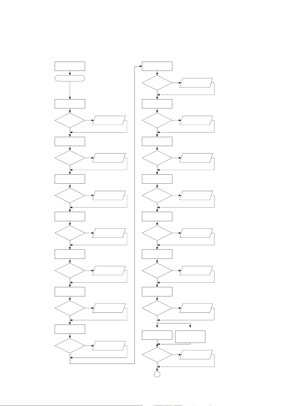
1.1.1 T1 test flow diagram, serial program steps
MODULE
T1
START T1 TEST
TEST
BYPASS
TEST OK?no
yes
TEST
OPT. DETECTOR
TEST OK?no
yes
TEST
BLOOD SYSTEM
TEST OK?no
yes
STORAGE
ERROR NUMBER
STORAGE
ERROR NUMBER
STORAGE
ERROR NUMBER
TEST
ACCUMULATOR
TEST OK?no
yes
TEST
BLOOD LEAK DETECTOR
TEST OK?no
yes
TEST
TEMPERATURE
TEST OK?no
yes
NEG. PRESSURE
HOLDING TEST
TEST OK?no
yes
STORAGE
ERROR NUMBER
STORAGE
ERROR NUMBER
STORAGE
ERROR NUMBER
STORAGE
ERROR NUMBER
TEST
VENOUS PRESSURE
TEST OK?no
yes
TEST
AIR DETECTOR
TEST OK?no
yes
TEST
DISPLAY
TEST OK?no
yes
TEST
ARTERIAL PRESSURE
TEST OK?no
yes
STORAGE
ERROR NUMBER
STORAGE
ERROR NUMBER
STORAGE
ERROR NUMBER
STORAGE
ERROR NUMBER
POS. PRESSURE
HOLDING TEST
TEST OK?no
yes
TEST
UF-FUNCTION
TEST OK?no
yes
TEST
CONDUCTIVITY
TEST OK?no
yes
Basic hydraulics Advanced hydraulics
TEST
DIASAFE/HDF FILTER
TEST OK?no
yes
STORAGE
ERROR NUMBER
STORAGE
ERROR NUMBER
STORAGE
ERROR NUMBER
TEST DIASAFE PLUS /
ONLINE PLUS /
HPU TEST
STORAGE
ERROR NUMBER
1
Fresenius Medical Care 4008 5/03.09 (TM) 1-3
Page 12
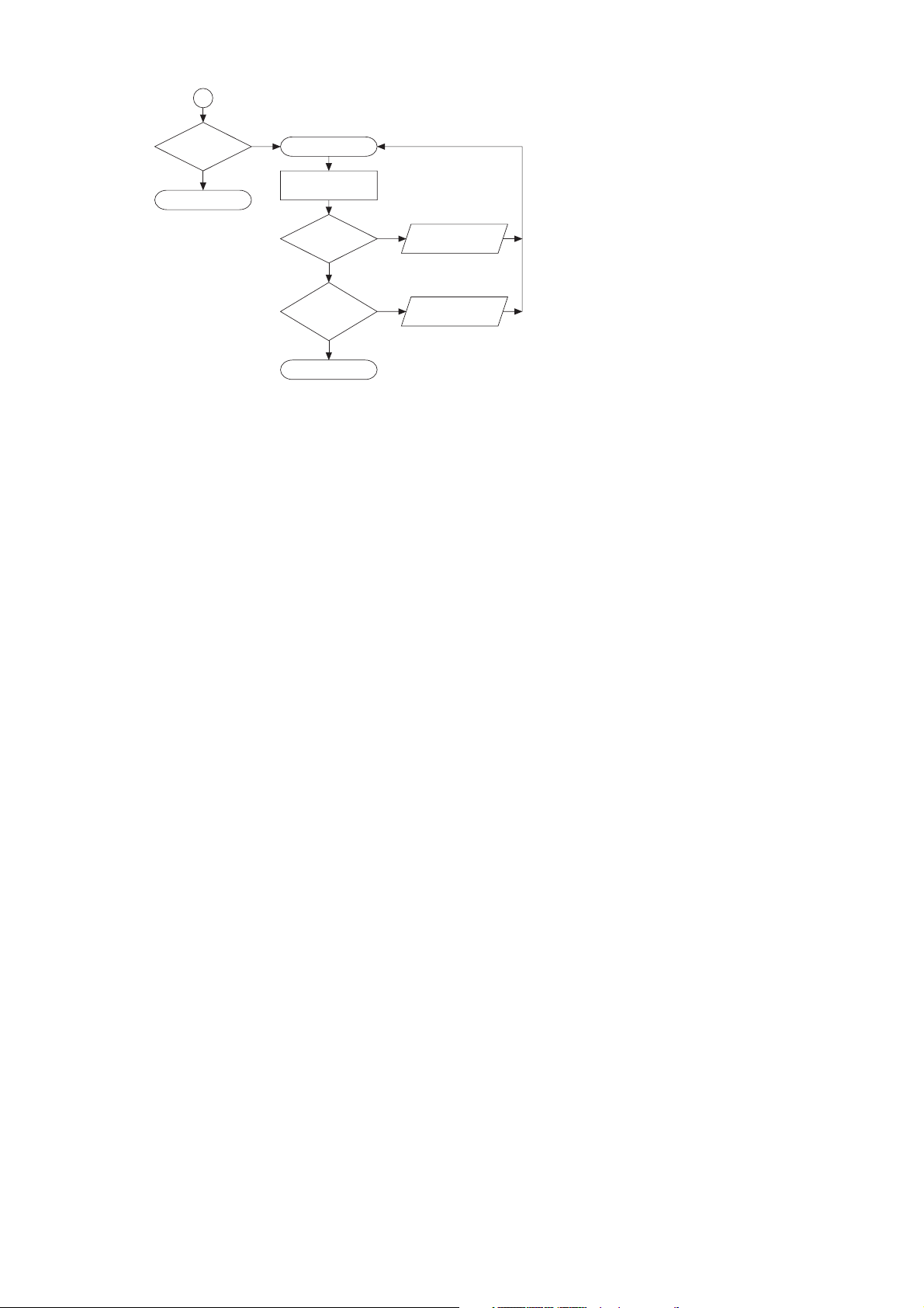
1
T1 TEST
UNSUCCESSFUL
no
RETURN
yes
DIALYSIS START KEY
INCORRECT
TEST STEP
TEST OK?no
yes
FURTHER
INCORRECT
TEST STEPS
no
RETURN
yes
ERROR
DISPLAY
NEXT INCORRECT
TEST STEP
1-4 Fresenius Medical Care 4008 5/03.09 (TM)
Page 13
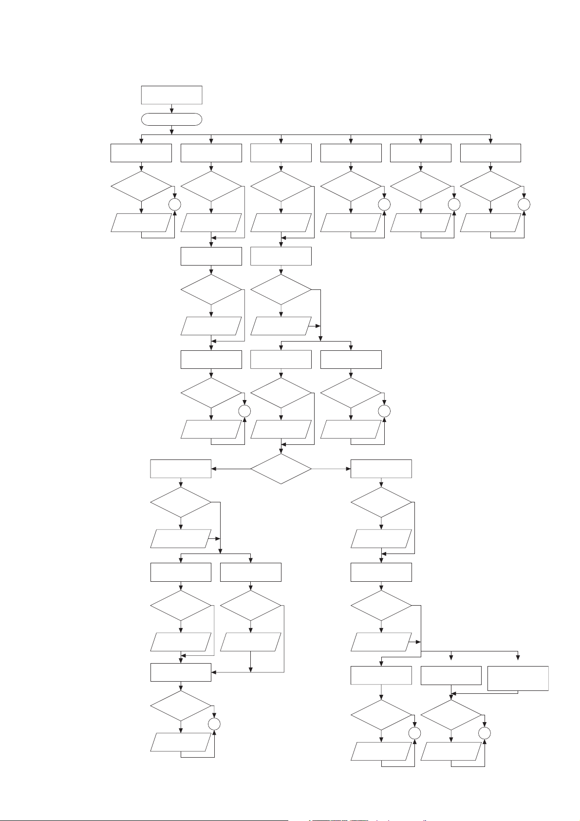
1.1.2 T1 test flow diagram, parallel program steps
/
MODULE
T1
START T1 TEST
TEST
OPT. DETECTOR
TEST OK
?
no
STORAGE
ERROR NUMBER
TEST
BLOOD SYSTEM
yes
TEST OK
?
1 1 1 1
STORAGE
ERROR NUMBER
TEST
VENOUS PRESSURE
TEST OK
?
STORAGE
ERROR NUMBER
TEST
AIR DETECTOR
TEST OK
?
STORAGE
ERROR NUMBER
yes
no
yes
no
yes
no
1 1
TEST
BYPASS
TEST OK
?
no
STORAGE
ERROR NUMBER
TEST
TEMPERATURE
TEST OK
?
no
STORAGE
ERROR NUMBER
NEG. PRESSURE
HOLDING TEST
TEST OK
?
no
STORAGE
ERROR NUMBER
TEST
DISPLAY
yes
TEST OK
?
STORAGE
ERROR NUMBER
yes
TEST
BLOOD LEAK DETECTOR
yes
TEST OK
?
STORAGE
ERROR NUMBER
TEST
ACCUMULATOR
yes
TEST OK
?
no
STORAGE
ERROR NUMBER
yes
no
yes
no
TEST
ARTERIAL PRESSURE
TEST OK
?
no
STORAGE
ERROR NUMBER
yes
POS. PRESSURE
HOLDING TEST
TEST OK
?
no
STORAGE
ERROR NUMBER
TEST
CONDUCTIVITY
TEST OK
?
no
STORAGE
ERROR NUMBER
TEST
DIASAFE/HDF FILTER
TEST OK
?
no
STORAGE
ERROR NUMBER
yes
yes
ERROR NUMBER
yes
1
TEST
UF-FUNCTION
TEST OK
?
no
STORAGE
Conductivity?
yes
yesno
TEST
CONDUCTIVITY
TEST OK
?
no
STORAGE
ERROR NUMBER
POS. PRESSURE
HOLDING TEST
TEST OK
?
no
STORAGE
ERROR NUMBER
TEST
UF-FUNCTION
TEST OK
?
no
STORAGE
ERROR NUMBER
yes
yes
Basic hydraulics Advanced hydraulics
TEST
TEST
DIASAFE/HDF FILTER
DIASAFE/HDF FILTER
yes yes
TEST OK
?
1 1
no
STORAGE
ERROR NUMBER
TEST DIASAFE PLUS
ONLINE PLUS /
HPU-TEST
Fresenius Medical Care 4008 5/03.09 (TM) 1-5
Page 14

1
T1 TEST
UNSUCCESSFUL
no
RETURN
yes
DIALYSIS START KEY
INCORRECT
TEST STEP
TEST OK?no
yes
FURTHER
INCORRECT
TEST STEPS
yes
RETURN
no
ERROR
DISPLAY
NEXT INCORRECT
TEST STEP
1-6 Fresenius Medical Care 4008 5/03.09 (TM)
Page 15

1.1.3 Description of the T1 test incl. error messages
● Prerequisites for starting and running the test
Error message Description
Power failure Power failure while the test is in progress
Dialines not conn The dialysate lines are not in the interlock shunt.
Shunt Cover open The interlock shunt is open.
Connect Conc.Line
Wrong conc. supply The concentrate connector is in the rinse chamber, or concen-
trate is not connected at all. The error message depends on the
central delivery system preselected in the setup menu.
Blood Sensed by OD The optical detector senses blood in the system.
Flow alarm Line to or from the dialyzer kinked, malfunctions in the hydraul-
ics.
Water alarm Water supply interrupted.
XXX not calibrated A valid calibration value is missing in the NOVRAM.
● Overview of the individual test steps
Bypass test ..................................................................................................................... 1-8
Optical detector test ....................................................................................................... 1-10
Blood system test ........................................................................................................... 1-12
Venous pressure system test ......................................................................................... 1-16
Air detector test .............................................................................................................. 1-18
Display test ..................................................................................................................... 1-22
Arterial pressure system test .......................................................................................... 1-24
Battery test ..................................................................................................................... 1-26
Blood leak test ................................................................................................................ 1-28
Temperature test ............................................................................................................ 1-30
Negative pressure holding test ....................................................................................... 1-32
Positive pressure holding test ........................................................................................ 1-34
UF function test .............................................................................................................. 1-39
Conductivity test ............................................................................................................. 1-42
Diasafe/HDF filter test .................................................................................................... 1-44
Online plus / Diasafe plus filter / HPU test ..................................................................... 1-48
Fresenius Medical Care 4008 5/03.09 (TM) 1-7
Page 16
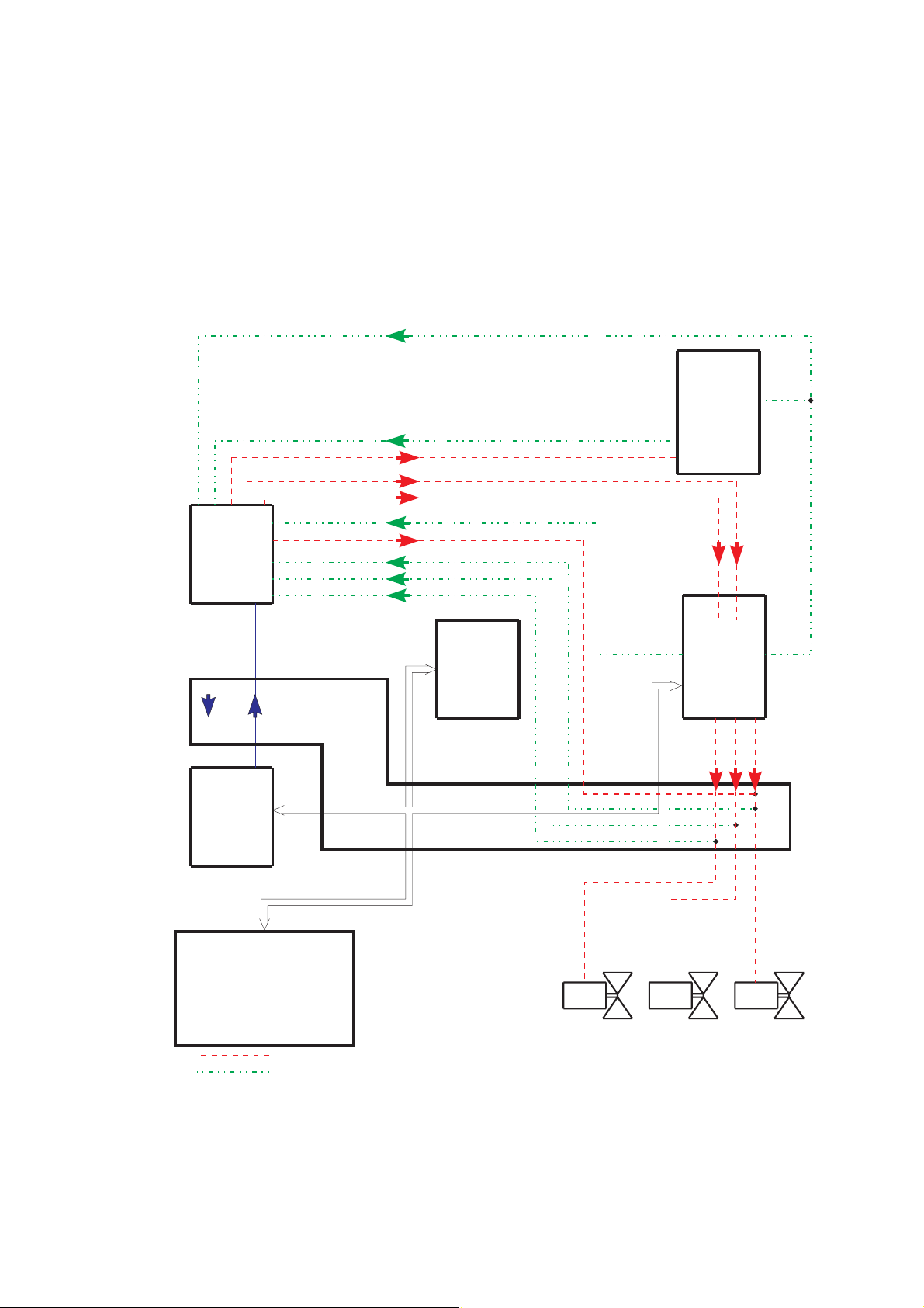
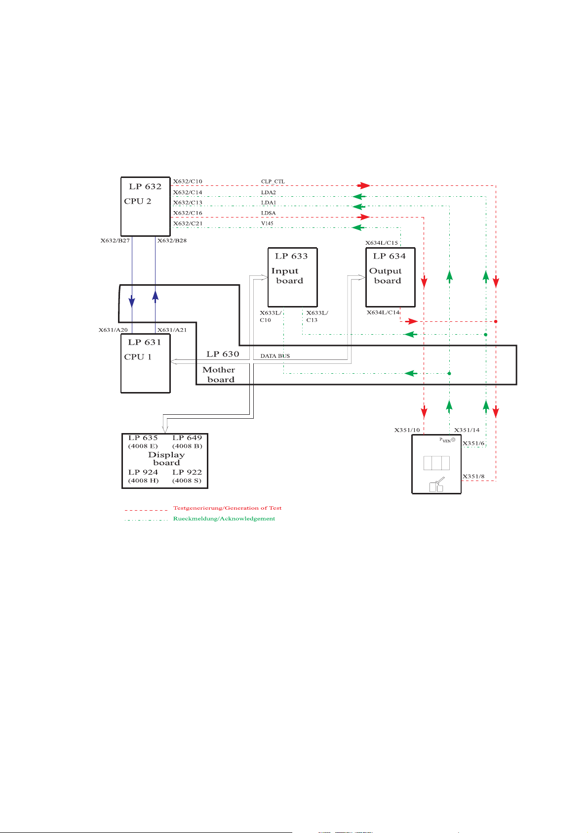
● Bypass test
H_REL_W
EM_H_OFF
V24_EN
V24B_EN
CI
V26
V24B
V24
V24
V24B
V26
X631/A20
X631/A21
X632/B27
X632/B28
X632/A4
X632/A5
X632/A6
X632/B22
X632/C26
X632/C25
X632/A6
X632/A9
X632/A10
X639/A12
X639/A17
C22
A18
X634R/
X634R/
V26
X634R/
X634R/
A23
V24
V24B
V26
X634L/C25
X634L/C12
X634L/A25
HOT_RINSE
C24
X639/
A20
X632/A26
Test description:
Check of the following functions:
– Heater relay
– Bypass (electric)
– Check of the temperature range changeover
Illustration:
LP 632
CPU 2
LP 639
(4008E/H)
Power
Logic
LP 647
(4008S/B)
LP 631
CPU 1
LP 635
(4008 E)
Display
LP 924
(4008 H)
LP 630
Mother
board
LP 649
(4008 B)
board
LP 922
(4008 S)
Testgenerierung/Generation of Test
Rueckmeldung/Acknowledgement
LP 633
Input
board
DATA BUS
LP 634
Output
board
1-8 Fresenius Medical Care 4008 5/03.09 (TM)
Page 17

Error description:
Error message Description
F 01 Bypass The heater relay is switched off.
– Acknowledgement (H_REL_W, X639/A12) → X632/A10, 0 V are
missing.
F 02 Bypass The heater relay cannot be switched off by CPU2.
– Acknowledgement (H_REL_W, X639/Y12) → X632/A10, 12 V are
missing.
– Control line (EM_H_OFF, X632/A9) → X639/A17, 12 V are missing.
F 03 Bypass The temperature measurement range is set to hot rinse.
– Control line (HOTRINSE, X634R/C24) → X639/A20, 0 V are miss-
ing.
– Acknowledgement (HOTRINSE, X634R/C24) → X632/A26, 0 V are
missing.
F 04 Bypass The extended bypass cannot be correctly switched by CPU2 (V24 = off,
V26 = on, V24B = off).
– Acknowledgement (V24, X637/C1) → X632/A4, 24 V are missing.
– Acknowledgement (V26, X637/C2) → X632/A6, 0 V are missing.
– Acknowledgement (V24B, X637/C23) → X632/A5, 24 V are miss-
ing.
F 05 Bypass The extended bypass cannot be correctly switched off by CPU2 (V24 =
on, V26 = off, V24B = on).
– Acknowledgement (V24, X637/C1) → X632/A4, 0 V are missing.
– Acknowledgement (V26, X637/C2) → X632/A6, 24 V are missing.
– Acknowledgement (V24B, X637/C23) → X632/A5, 0 V are missing.
F06 Bypass CPU1 fails to set the temperature control to hot rinse.
– Control line (HOTRINSE, X634R/C24) → X639/A20, 12 V are miss-
ing.
– Acknowledgement (HOTRINSE, X634R/C24) → X632/A26, 12 V
are missing.
F 07 Bypass The extended bypass cannot be correctly switched by CPU1 (V24 = off,
V26 = on, V24B = off).
– Acknowledgement (V24, X637/C1) → X632/A4, 24 V are missing.
– Acknowledgement (V26, X637/C2) → X632/A6, 0 V are missing.
– Acknowledgement (V24B, X637/C23) → X632/A5, 24 V are miss-
ing.
F08 Bypass CPU1 fails to reset the temperature control to dialysis.
– Control line (HOTRINSE, X634R/C24) → X639/A20, 0 V are miss-
ing.
– Acknowledgement (HOTRINSE, X634R/C24) → X632/A26, 0 V are
missing.
F09 Bypass The extended bypass cannot be correctly switched off by CPU1 (V24 =
on, V26 = off, V24B = on).
– Acknowledgement (V24, X637/C1) → X632/A4, 0 V are missing.
– Acknowledgement (V26, X637/C2) → X632/A6, 24 V are missing.
– Acknowledgement (V24B, X637/C23) → X632/A5, 0 V are missing.
F95 Bypass System error
Fresenius Medical Care 4008 5/03.09 (TM) 1-9
Page 18
● Optical detector test
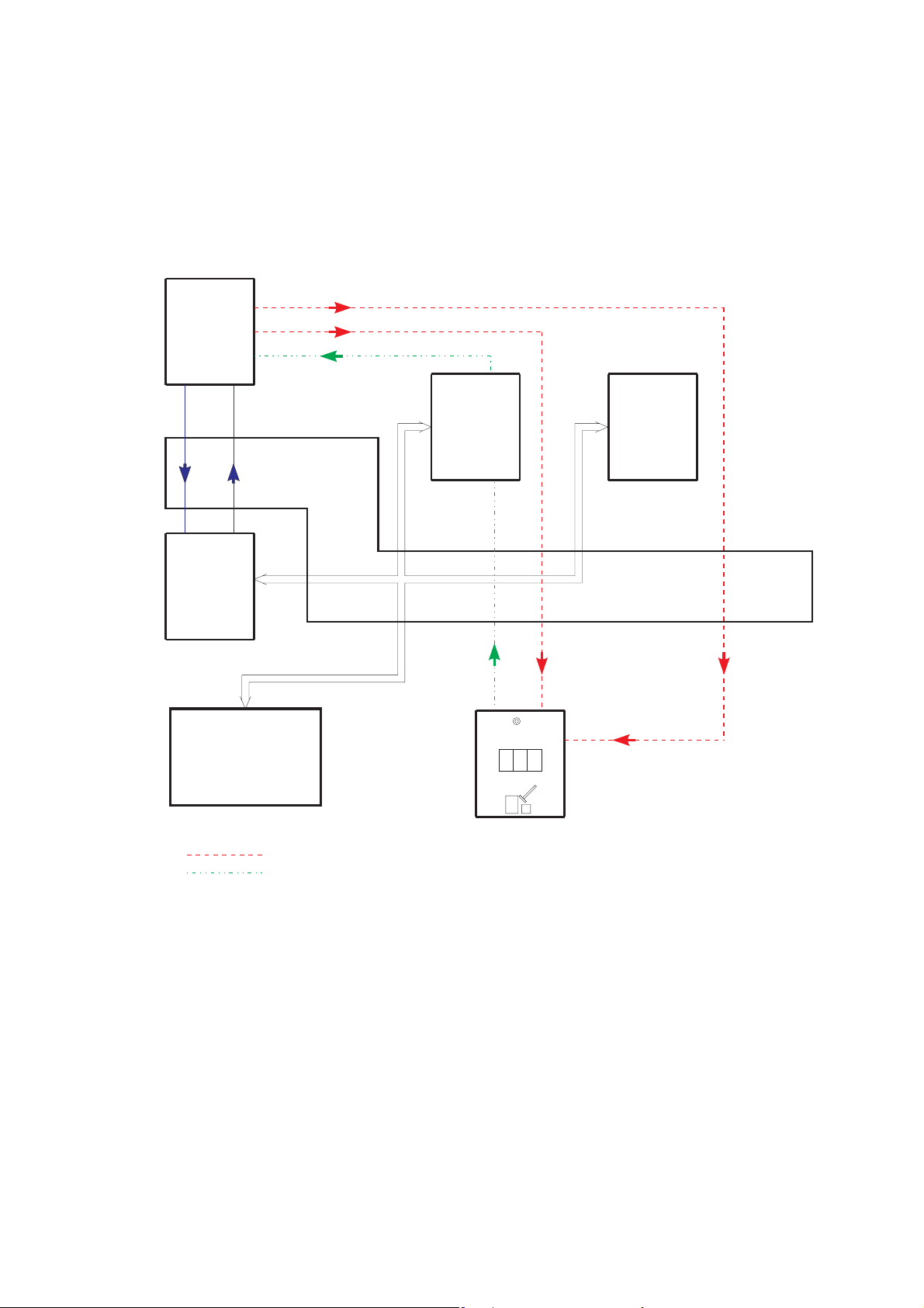
Test description:
Attenuation of the optical detector.
Check of the acknowledgement of the optical detector.
Illustration:
LP 632
CPU 2
B27
A20
LP 631
CPU 1
LP 635
(4008 E)
LP 924
(4008 H)
X632/B28
X631/A21
Display
board
X632/C16
X632/C15
X632/A30
LP 649
(4008 B)
LP 922
(4008 S)
LP 630
Mother
board
LDSA
ODSA
OD_OUT
X633L/C7
LP 633
Input
board board
X633L/C8
OD_IN
DATA BUS
X351/5
Pven
X351/7
X351/10
LP 634
Output
Testgenerierung/Generation of Test
Rueckmeldung/Acknowledgement
1-10 Fresenius Medical Care 4008 5/03.09 (TM)
Page 19

Error description:
Error message Description
F01 opt. Detector CPU1 interprets the optical detector in a different way than does CPU2.
– Acknowledgement (OD_OUT, X633L/C7) → X632/A30 and the
digital input of P.C.B. LP 633 measure different levels.
F02 opt. Detector CPU2 fails to recognize blood in the system.
– Acknowledgement (OD_OUT, X633L/C7) → X632/A30, 0 V are
missing.
– Detuning (ODSA, X632/C15) → X351/7 not 12V.
F03 opt. Detector CPU1 fails to recognize blood in the system.
– Acknowledgement (OD_OUT, X633L/C7) → digital input on P.C.B.
LP 633.
– Detuning (ODSA, X632/C15) → X351/7 not 12V.
F04 opt. Detector CPU2 recognizes that the optical detector senses opaque fluid (re-
quired because of the test in the cleaning program).
– Acknowledgement X632/A30 not 12V.
– AD28 defective.
F96 opt. Detector System error.
Fresenius Medical Care 4008 5/03.09 (TM) 1-11
Page 20
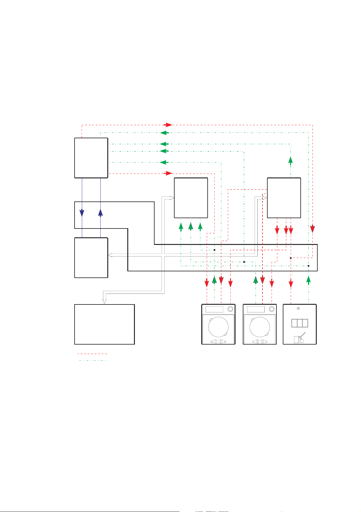
● Blood system test
Test description:
Check of the following functions:
– Blood alarm acknowledgement
– Blood pump switch-off
Illustration:
X632/B27
X631/A20
LP 632
CPU 2
LP 631
CPU 1
X632/C10
X632/C14
X632/C21
X632/B11
X632/A11
X632/A15
X632/B28
X631/A21
LP 630
Mother
board
CLP_CTL
LDA2
BL_AL
BPSB_VEN
BPSB_ART
SN_ART
X633L/
C13
DATA BUS
LP 633
Input
board
A13
X633L/
X634L/
C15
X634L/
A14
A15
LP 634
(4008E/H)
Output
board
LP 647
(4008S/B)
BPST_ART
BPSST_A
X634L/
B14
B15
BPSST_V
X634L/
C14
LP 635
(4008 E)
Display
LP 924
(4008 H)
LP 649
(4008 B)
board
LP 922
(4008 S)
Testgenerierung/Generation of Test
Rückmeldung/Acknowledgement
X348a/2
X348a/6
X348a/3
X348a/1
X348/V6
X348/V3
X348/V1
Pven
X351/8
X351/6
1-12 Fresenius Medical Care 4008 5/03.09 (TM)
Page 21

Error description:
Error message Description
F09 Bloodsystem Acknowledgement that CPU2 recognizes that the arterial blood pump
is inactive (BP not running).
– Acknowledgement (BPSB_ART, X348a/6) → X632/A11, 12 V miss-
ing.
– Control line (BPSST_ART, X634L/B14) → X348a/1, 12 V missing or
(BPST_ART, X634L/A14) → X348a/3, 12 V are missing.
F10 Bloodsystem Acknowledgement that CPU1 recognizes that the arterial blood pump
is inactive (BP not running).
– Acknowledgement (BPSB_ART, X348a/6) → X633L/A11, 12 V are
missing.
– Control line (BPSTT_ART, X634L/B14) → X348a/1, 12 V missing or
(BPST_ART, X634L/A14) → X348a/3, 12 V missing.
– Level is raised during the T1 test.
F11 Bloodsystem The arterial blood pump cannot be stopped by CPU1.
CPU2 recognizes that the arterial blood pump remains active.
– Control line (BPSST_ART, X634L/B14) → X348a/1, 0 V missing,
as well as (BPST_ART, X634L/A14) → X348a/3, 0 V missing.
– Acknowledgement (BPSB_ART, X348a/6) → X632/A11, 0 V are
missing.
– The level is raised during the T1 test, or the up/down key on the air
detector is blocked and the level is constantly raised.
F12 Bloodsystem The arterial blood pump cannot be stopped by CPU1.
CPU1 recognizes that the arterial blood pump remains active.
– Control line (BPSST_A, X634L/B14) → X348a/1, 0 V missing,
as well as (BPST_ART, X634L/A14) → X348a/3, 0 V missing.
– Acknowledgement (BPSB_ART, X348a/6) → X633L/A11, 0 V are
missing.
F13 Bloodsystem
Applicable for SW 4.91/2.91 and higher if SN, ONLINE-HDF or
4008 HDF pump is connected (= ADKS active)
Acknowledgement that CPU2 detects that the pump is inactive (pump
is not running).
– Acknowledgement (BPSB_VEN, X348V/6) → X632/ B11, 12V
missing
– Control line (BPSST_VEN, X634L/B15) → X348V/1, 12V missing or
(BPST_VEN, X634L/A15) → X348V/3, 12V missing
– Transistor T9 on P.C.B. LP 754 defective
– IC5 on P.C.B. LP 632 defective
– In 4008 HDF an HDF treatment was performed, followed by a
cleaning program with the substituate pump running, then the T1
test has been re-started.
The substituate pump must be switched off because otherwise the
test step will fail to be passed (problem was corrected with SW 3.20
in 4008 H/S systems: the substituate pump will be switched off
automatically on starting a cleaning program).
Fresenius Medical Care 4008 5/03.09 (TM) 1-13
Page 22

F14 Bloodsystem
Applicable for SW 4.91/2.91 and higher if SN, ONLINE-HDF or
4008 HDF pump is connected (= ADKS active)
Acknowledgement that CPU1 detects that the pump is inactive (pump
is not running).
– Acknowledgement (BPSB_VEN,X348V/6) → X633L/A13, 12V
missing
– Control line (BPSST_VEN, X634L/B15) → X348V/1 not 12V or
(BPST_VEN, X634L/A15) → X348V/3 not 12V
– IC16 on P.C.B. LP 633 defective
– P.C.B. LP 633 recognizes Single-Needle pump although it is not
connected.
F15 Bloodsystem
F16 Bloodsystem
Applicable for SW 4.91/2.91 and higher if SN, ONLINE-HDF or
4008 HDF pump is connected (= ADKS active)
CPU1 fails to stop the corresponding blood pump.
CPU2 detects that the pump remains active.
– Control line (BPSST_VEN, X634L/B15) → X348V/1, 0V missing as
well as (BPST_VEN, X634L/A15) → X348V/3 not 0V
– Acknowledgement (BPSB_VEN, X348V/6) → X632/B11, 0V miss-
ing
– Transistor T9 on P.C.B. LP 754 defective
– IC5 on P.C.B. LP 632 defective
– During the test the lines are inserted on the corresponding pump
using the Start/Stop key.
– P.C.B. LP 633 recognizes Single-Needle pump although it is not
connected.
Applicable for SW 4.91/2.91 and higher if SN, ONLINE-HDF or
4008 HDF pump is connected (= ADKS active)
CPU1 fails to stop the corresponding blood pump.
CPU1 detects that the pump remains active.
– Control line (BPSST_VEN, X634L/B15) → X348V/1 not 0V as well
as (BPST_VEN, X634L/A15) → X348V/3 not 0V
– Acknowledgement (BPSB_VEN, X348V/6) → X633L/A13 not 0V
– IC16 on P.C.B. LP 633 defective
– P.C.B. LP 633 recognizes Single-Needle pump although it is not
connected.
F17 Bloodsystem
Applicable for SW 4.91/2.91 and higher if SN, ONLINE-HDF or
4008 HDF pump is connected (= ADKS active)
Although the recognition of the venous blood pump (ADKS) is not
acknowledged, the 24-V supply voltage of the pump can be switched
off.
– Acknowledgement line (ADKS, X348V/7) → X633L/A10 not 12V
– Acknowledgement (BPSB_VEN, X348V/6) → X633L/A13 not 12V
– Acknowledgement (BPSB_VEN, X348V/6) → X632/B11 not 12V
– Online-HDF has already been switched on during the T1 test.
– IC16 on P.C.B. LP 633 defective.
1-14 Fresenius Medical Care 4008 5/03.09 (TM)
Page 23

F18 Bloodsystem
Applicable for SW 5.00/4.10 and higher, check of the BPUS signal
(CPU, P.C.B. LP 632)
At the beginning of the test step a maximum of 40s may pass until
rotation has stopped.If the blood pump is being activated, the rotation
stop alarm must have been cleared.
– Acknowledgement line (BPUS, X348A/8) → X632/A13 not 0V
– Acknowledgement line (BPUS, X348A/8) → X632/A13 not 12V
– Blood pump speed is set to “0”: preset speed during the T1 test.
F19 Bloodsystem
Applicable for SW 5.00/4.10 and higher, check of the BPUS signal
(CPU, P.C.B. LP 631 via LP633)
At the beginning of the test step a maximum of 40s may pass until
rotation has stopped. If the blood pump is being activated, the rotation
stop alarm must have been cleared.
1. Acknowledgement line (BPUS, X348A/8) → X633L/A12 not 0V
2. Acknowledgement line (BPUS, X348A/8) → X633L/A12 not 12V
F20 Bloodsystem Check of the actual arterial BP rate.
The actual rate of the arterial BP is not zero. The actual rate of the
arterial BP does not increase.
If SN is installed: The actual rate of the venous BP is not zero. The
actual rate of the venous BP does not increase.
– Acknowledgement line (BPR_ART, X348A/10) → X633L/B3 not 0V
or acknowledgement line (BPR_ART, X348A/10) → X632/A14 not
0V
– Acknowledgement line (BPR_ART, X348A/10) → X633L/B3 no
increase or acknowledgement line (BPR_ART, X348A/10) → X632/
A14 no increase
If SN is installed:
– Acknowledgement line (BPR_VHDF, X348V/10) → X633L/B4 not
0V
– Acknowledgement line (BPR_VHDF, X348V/10) → X633L/B4 no
increase
F95 Bloodsystem System error.
Fresenius Medical Care 4008 5/03.09 (TM) 1-15
Page 24
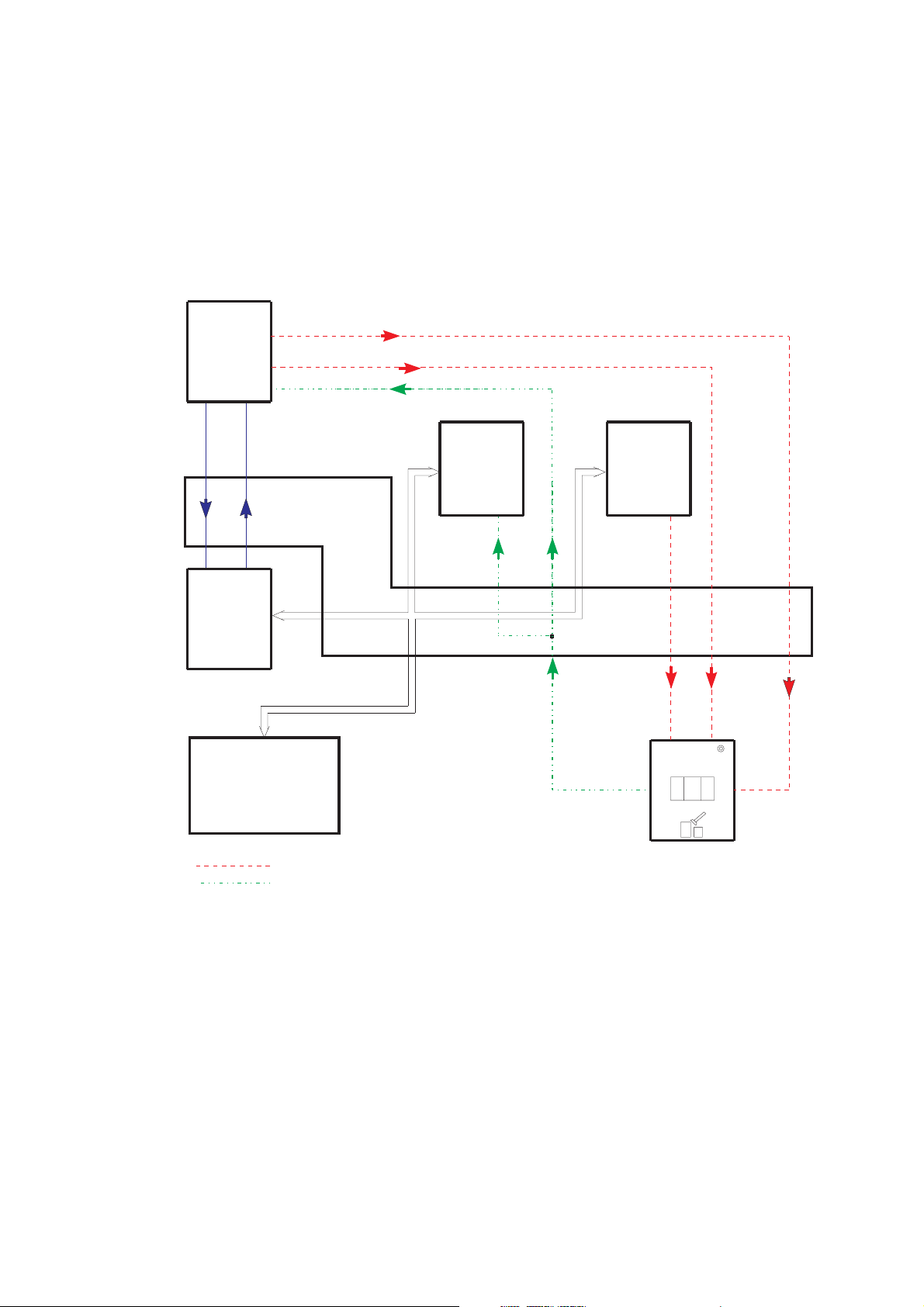
● Venous pressure system test
X
X
Test description:
Verification of the lower limit by checking the venous zero point.
The upper limit is tested by detuning the venous pressure unit in positive direction.
(The venous line clamp is closed during the test.)
Illustration:
LP 632
X632/C16
LDSA
CPU 2
PV_DET
P_VEN
Input
LP 633
LP 634
Output
632/B27
X632/C18
X632/C17
X632/B28
boardboard
X634R/C18
VENT_V
631/A20
LP 631
CPU 1
X631/A21
LP 630
X633L/B5
DATA BUS
Mother
board
LP 635
(4008 E)
LP 649
X351/1
(4008 B)
X351/2
P
VEN
Display
board
LP 924
(4008 H)
LP 922
(4008 S)
X351/4
X351/10
Testgenerierung/Generationof Test
Rueckmeldung/Acknowledgement
1-16 Fresenius Medical Care 4008 5/03.09 (TM)
Page 25

Error description
Error message Description
F01 Venous CPU1 (input board) shows a venous zero point deviation of more than
±12 mmHg (60 s).
– Control (VENT_VALVE, X634R/C18) → X351/1 of the vent valve in
the LD is defective.
– Acknowledgement (P_VEN, X351/4) → X633L/B5 that the voltage
value is outside the zero point tolerance.
– P-venous has not been calibrated.
F02 Venous CPU2 shows a venous zero point deviation of more than ±12 mmHg
(60 s).
– Control (VENT_VALVE, X634R/C18) → X351/1 of the vent valve in
the LD is defective.
– Acknowledgement (P_VEN, X351/4) → X632/C17, the voltage
value is outside the zero point tolerance.
– P-venous has not been calibrated.
F03 Venous With detuning in positive direction, the achieved change in the venous
display is less than 100 mmHg (7 s).
– The test detuning is defective (PV_DET, X632/C18) → X351/2.
– Acknowledgement (P_VEN, X351/4) → X633L/B5, the change in
voltage is too low.
– P-venous has not been calibrated.
F04 Venous The deviation in the measured value between CPU1 and CPU2 is
higher than ±12 mmHg (if Pven > 100 mmHg).
– Acknowledgement (P_VEN, X351/4) → X633L/B5 and X632/C17
measure different voltage values.
– P-venous has not been calibrated.
F95 Venous System error.
Fresenius Medical Care 4008 5/03.09 (TM) 1-17
Page 26
● Air detector test
Test description:
– Test of the air detector by checking the alarm state.
– Switch-off of the venous line clamp in the air detector module.
Illustration:
1-18 Fresenius Medical Care 4008 5/03.09 (TM)
Page 27

Error description:
Error message Description
F01 Airdetector CPU1 interprets the air detector signal in a different way than does
CPU2.
– Acknowledgements (LDA1, X351/14) → X632/C13 and X633L/C10
recognize different signal levels.
F02 Airdetector The air detector alarm is not recognized by CPU2.
– Acknowledgement (LDA1, X351/14) → X632/C13, 0 V are missing.
– Transmission weakening (LDSA, X632/C16) → X351/10, 12 V are
missing.
F03 Airdetector Air detector clamps acknowledgement (CPU2) activated (clamp
closed).
– Acknowledgement (LDA2, X351/6) → X632/C14, 24 V are missing.
– Clamp control (CLP_CTL, X634L/C14) → X351/8, 12 V are missing.
– Clamp control (CLP_CTL, X632/C10) → X351/8, 12 V are missing.
F04 Airdetector Air detector clamps acknowledgement (CPU1) activated (clamp
closed).
– Acknowledgement (LDA2, X351/6) → X633L/C13, 24 V are miss-
ing.
– Clamp control (CLP_CTL, X634L/C14) → X351/8, 12 V are missing.
– Clamp control (CLP_CTL, X632/C10) → X351/8, 12 V are missing.
F05 Airdetector The blood alarm signal has not been cleared (indicates an alarm).
– Acknowledgement (BL_AL, X634L/C15) → X632/C21, 12 V are
missing.
If the HDF option is used, this signal is not tested (special function).
F06 Airdetector Closing of the air detector clamp via the CPU2 control line was not
possible.
– Clamp control (CLP_CTL, X632/C10) → X351/8, 0 V are missing.
– Acknowledgement (LDA2, X351/6) → X632/C14, 0 V are missing.
F07 Airdetector Opening of the air detector clamp via the CPU2 control line was not
possible.
– Clamp control (CLP_CTL, X632/C10) → X351/8, 12 V are missing.
– Acknowledgement (LDA2, X351/6) → X632/C14, 24 V are missing.
F08 Airdetector Closing of the air detector clamp via the CPU1 control line was not
possible, or CPU2 acknowledgement is incorrect.
– Clamp control (CLP_CTL, X634L/C14) → X351/8, 0 V are missing.
– Acknowledgement (LDA2, X351/6) → X632/C14, 0 V are missing.
Fresenius Medical Care 4008 5/03.09 (TM) 1-19
Page 28

F09 Airdetector Closing of the air detector clamp via the CPU1 control line was not
possible, or CPU1 acknowledgement is incorrect.
– Clamp control (CLP_CTL, X634L/C14) → X351/8, 0 V are missing.
– Acknowledgement (LDA2, X351/6) → X633L/C13, 0 V are missing.
F10 Airdetector The blood alarm message is missing.
– Acknowledgement (BL_AL, X634R/C15) → X632/C21, 0 V are
missing.
If the HDF option is used, this signal is not tested (special function).
F11 Airdetector Air detector clamps acknowledgement (CPU2) activated (clamp
closed).
– Acknowledgement (LDA2, X351/6) → X632/C14, 24 V are missing.
– Clamp control (CLP_CTL, X634L/C14) → X351/8, 12 V are missing.
– Clamp control (CLP_CTL, X632/C10) → X351/8, 12 V are missing.
F12 Airdetector Air detector clamps acknowledgement (CPU1) activated (clamp
closed).
– Acknowledgement (LDA2, X351/6) → X633L/C13, 24 V are miss-
ing.
– Clamp control (CLP_CTL, X634L/C14) → X351/8, 12 V are missing.
– Clamp control (CLP_CTL, X632/C10) → X351/8, 12 V are missing.
F13 Airdetector The blood alarm signal has not been cleared (indicates alarm).
– Acknowledgement (BL_AL, X634L/C15) → X632/C21, 12 V are
missing.
If the HDF option is used, this signal is not tested (special function).
F14 Airdetector Raise level key on the air detector is constantly active.
– Acknowledgement (LEVEL_UP, X351/3) → X632/C11 not 0V.
F15 Airdetector Acknowledgement of the supply voltage for the ultrasonic output stage
not between 6.5 and 13.5 V after 3 seconds.
– Adapter board AD28 not connected
– Acknowledgement (X351/11 → X633L/25A jumper to X633L/B7)
not 12V.
– Relay on AD28 failed to drop.
F16 Airdetector Acknowledgement of the supply voltage for the ultrasound output stage
not >14.5V after 3 seconds.
– Adapter board AD28 not connected.
– Acknowledgement (X351/11 → X633L/25A jumper to X633L/B7)
not 16V/24V.
– Relay on AD28 is not controlled.
– No 10-Hz signal at ALARM_REST (X351/12)
1-20 Fresenius Medical Care 4008 5/03.09 (TM)
Page 29

F17 Airdetector Acknowledgement of the supply voltage for the ultrasound output stage
not between 6.5 and 13.5 V after 3 seconds.
– Adapter board AD28 not connected
– Acknowledgement (X351/11 → X633L/25A jumper to X633L/B7)
not 12V
– Relay on AD28 failed to drop
F95 Airdetector System error.
Fresenius Medical Care 4008 5/03.09 (TM) 1-21
Page 30
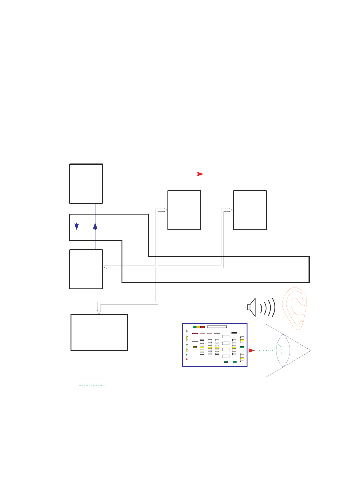
● Display test
Test description:
Check of all displays and indicators on the monitor front
– Display test
– Status LED
– Alarm LED
– Seven-segment display, all dark
– Seven-segment display, all 8888
– Bar graph
– CPU1/CPU2 alarm tone
This display test must be monitored by the user!
Illustration:
X632/ B27
X631/ A20
LP 632
CPU 2
LP 631
CPU 1
LP 635
(4008 E)
LP 924
(4008 H)
X632/ B28
X631/ A21
Display
board
X632/C29
LP 649
(4008 B)
LP 922
(4008 S)
LP 630
Mother
board
CPU2_AL
LP 633
Input
board board
DATA BUS
Test Display
8888
8888
8888
8888
X634R/A16
LP 634
Output
+LS X634L/A13
-LS X634L/B13
Testgenerierung/Generation of Test
Rueckmeldung/Acknowledgement
1-22 Fresenius Medical Care 4008 5/03.09 (TM)
Page 31

Error description:
Error message Description
F01 Display CPU1 failed to start the display test within 5 sec.
– The “test started” information transmitted via the serial interface is
missing.
F02 Display CPU1 failed to complete the display test within 120 sec.
– The “test completed” information transmitted via the serial interface
is missing.
F95 Display System error.
Fresenius Medical Care 4008 5/03.09 (TM) 1-23
Page 32

● Arterial pressure system test
Test description:
Test of the arterial pressure unit by electronic detuning in positive or negative direction.
Illustration:
1-24 Fresenius Medical Care 4008 5/03.09 (TM)
Page 33

Error description:
Error message Description
F01 Arterial With detuning in negative direction, the change achieved on the arterial
display is less than 100 mmHg (2 sec).
– Acknowledgement (P_ART, X348A/7) → X633L/B12, insufficient
voltage change.
– Test detuning defective (PA_DET, X632/A17) → X348A/9.
F02 Arterial With detuning in positive direction, the change achieved on the arterial
display is less than 100 mmHg (2 sec).
– Acknowledgement (P_ART, X348A/7) → X633L/B12, insufficient
voltage change.
– Test detuning defective (PA_DET, X632/A17) → X348A/9.
F95 Arterial System error.
Fresenius Medical Care 4008 5/03.09 (TM) 1-25
Page 34

● Battery test
)
Test description:
Check of the battery voltage under load.
Illustration:
X632/B27
X631/A20
LP 632
CPU 2
LP 631
CPU 1
LP 635
(4008 E)
LP 924
(4008 H)
X632/B28
X631/A21
Display
board
LP 649
(4008 B)
LP 922
(4008 S)
LP 630
Mother
board
LP 633
Input
board
X633L/B21
DATA BUS
X634R/C23
LP 634
Output
board
TESTBATT
U_ACCU
X639/A10
LP 639
(4008E/H)
Power
Logic
LP 647
(4008S/B)
X639/A2
X639/A3
X639/A4
Akku
(16 - 22V
Testgenerierung/Generationof Test
Rueckmeldung/Acknowledgement
1-26 Fresenius Medical Care 4008 5/03.09 (TM)
Page 35

Error description:
Error message Description
F01 Accumulator CPU1 failed to complete the battery test within 5 sec.
– The “test completed” information transmitted via the serial interface
is missing.
F02 Accumulator The battery charge is insufficient for 15 min emergency operation
(maybe no battery connected).
– The battery voltage (U_ACCU, ...) → X633L/B21 dropped below
17.6 V.
– Acknowledgement (U_ACCU, ...) → X633L/B21 of the battery volt-
age defective.
F03 Accumulator The test circuit on P.C.B. LP 639 defective.
– The test level is incorrect (TESTBATT, X634R/C23) → X639/A10,
the 12-V pulse is missing (100 ms).
– Power supply unit LP 639 SI5 or in 4008B/S systems fuse in the
base defective.
– R39 on P.C.B. LP 639 (4008E/H) or P.C.B. LP 647 (4008B/S) de-
fective, possibly caused by flickering power supply unit.
F95 Accumulator System error.
Fresenius Medical Care 4008 5/03.09 (TM) 1-27
Page 36

● Blood leak test
Test description:
Test of the blood leak detector by lowering the capacity of the transmitting diode.
Illustration:
1-28 Fresenius Medical Care 4008 5/03.09 (TM)
Page 37

Error description:
Error message Description
F01 Bloodleak Blood leak channel and dimness not in alarm-free condition during the
T1 test.
– Dimness channel contaminated (calcium precipitate, etc.)
– Acknowledgement (BLL, X637A/18) → X633L/B10 voltage value
within the alarm tolerances (< 3V).
– Acknowledgement (BLL_DIM, X637A/21) → X633L/B11 voltage
value within the alarm tolerances (<1.5V/ >8V).
– DAC_BLL or DAC_DIM not within the tolerances (check calibration)
F02 Bloodleak The blood leak alarm/dimness alarm is not recognized during test
detuning.
– Acknowledgement (BLL, X637A/18) → X633L/B10 voltage value
not within the alarm tolerances.
– Acknowledgement (BLL_DIM, X637A/21 → X633L/B11 voltage val-
ue not within the alarm tolerances (<1.5V)
– Test detuning (BLL_DET, X632/A25) → X633L/B27 not 5V
– Calibration of DAC_BLL or DAC_DIM is too high
– Detuning (DAC_DIM, X634R/A11) → X633L/C3 impossible
– Dimness calibration is set to potentiometer calibration (BR6 from
pos. 1/2 to 2/3).
F03 Bloodleak After test detuning, the blood leak channel and dimness fail to enter the
alarm-free state.
– Dimness channel contaminated (calcium precipitate, etc.)
– Acknowledgement (BLL, X637A/18) → X633L/B10 voltage value
within the alarm tolerances
– Test detuning (BLL_DET, X632/A25) → X633L/B27 not 0V.
– Acknowledgement (BLL_DIM, X637A/21) → X633L/B11 voltage
value within the alarm tolerances (<1.5V / >8V).
– DAC_BLL or DAC_DIM not within the tolerances (check calibration)
F95 Bloodleak System error.
Fresenius Medical Care 4008 5/03.09 (TM) 1-29
Page 38

● Temperature test
Test description:
Test of the upper alarm limit by electronically detuning the temperature display in positive
direction.
Illustration:
LP 639
(4008E/H)
Logic
LP 647
(4008S/B)
X634R/
A13
BIBAG_TE
LP 634
Output
board
X634R/C24
X632/B27
LP 632
CPU 2
X632/A26
X632/A24
X632/A23
X632/B28
HOTRINSE
T_DIAL1
T_DETADJ
X633R/C21
LP 633
Input
board
X633L/B16
X633R/
A20
X631/A20
LP 631
CPU 1
LP 635
(4008 E)
LP 924
(4008 H)
X631/A21
LP 630
Mother
board
LP 649
(4008 B)
Display
board
LP 922
(4008 S)
Testgenerierung/Generation of Test
Rueckmeldung/Acknowledgement
X633R/C25
DATA BUS
MON_NTC
X633R/C15
NTC_BIB
LP 639
(4008E/H)
Power
Logic
LP 647
(4008S/B)
X639/A20
1-30 Fresenius Medical Care 4008 5/03.09 (TM)
Page 39

Error description:
Error message Description
F01 Temperature The temperature measuring range is not set to hemodialysis.
– Control line (HOTRINSE, X634R/C24) → X639/A20, 0 V are miss-
ing.
– Acknowledgement (HOTRINSE, X634R/C24) → X632/A26, 0 V are
missing.
F02 Temperature The actual temperature is less than 35.0 °C (test running time > 15
minutes).
– Calibrate the temperature.
– The heater rod failed.
– Acknowledgement (T_DIAL1, X633L/B16) → X632/A24, voltage got
stuck.
F03 Temperature The actual temperature is higher than 39.0 °C (test running time > 15
minutes).
– Calibrate the temperature.
– The regulating sensor (NTC-2) is defective.
– Acknowledgement (T_DIAL1, X633L/B16) → X632/A24, voltage got
stuck.
F04 Temperature The temperature failed to stabilize within 15 minutes.
– Acknowledgement (T_DIAL1, X633L/B16) → X632/A24 is steadily
changing (change > 0.3 °C/15 sec).
F05 Temperature Detuning in positive direction not higher than 3 °C (10 sec).
– Acknowledgement (T_DIAL1, X633L/B16) → X632/A24, change in
voltage insufficient.
– Detuning (T_DETADJ, X632/A23) → X633R/C21 insufficient.
F06 Temperature The monitor sensor indicates a constant value.
– NTC-3 defective.
F07 Temperature The test release is missing (max. test running time is 10 minutes).
– Run-time problem (software).
F08 Temperature CPU1 failed to transmit a Bibag status message within 3 sec.
– Run-time problem (software).
F09 Temperature Bibag NTC_BIB detuning not higher than 1 °C.
– Acknowledgement (NTC_BIB, X633R/C15) → ADW on P.C.B.
LP 633, change in voltage insufficient.
– Detuning (BIBAG_TE, X634R/A13) → X633R/A20 insufficient.
F10 Temperature Bibag temperature display outside of measuring range (15 to 45 °C).
– Acknowledgement (NTC_BIB, X633R/C15) → ADW on P.C.B.
LP 633.
F95 Temperature System error.
Fresenius Medical Care 4008 5/03.09 (TM) 1-31
Page 40

● Negative pressure holding test
Test description:
Within a specific time period, the actual value of the dialysate pressure transducer should change
within certain limits only.
Illustration:
X632/B27
X631/A20
LP 632
CPU 2
LP 631
CPU 1
LP 635
(4008 E)
LP 924
(4008 H)
X632/B28
X631/A21
Display
board
X632/A19
X632/B22
X632/C27
X632/A29
LP 649
(4008 B)
LP 922
(4008 S)
LP 630
Mother
board
ACKN_ASP
CI
UF_P_CTL
P_DIAL
LP 633
Input
board
DATA BUS
X633L/B6
X633R/C28
+P_DIAL
X634R/A24
LP 634
Output
board
X634R/A24
UF_P_CTL
X634R/A23
X634L/B10
Testgenerierung/Generation of Test
Rueckmeldung/Acknowledgement
1-32 Fresenius Medical Care 4008 5/03.09 (TM)
Page 41

Error description:
Error message Description
F01 neg. Pressure During the start phase a negative pressure of more than 450 mmHg
has developed (max. test running time 120 sec),
– the hydraulic system is contaminated,
– the air separation pump started running.
F02 neg. Pressure Setting the dialysate pressure to the test pressure (–300 mmHg to
–450 mmHg) was not possible (max. test running time 120 sec).
Upon repetition of measurement, the range was extended from
–260 mmHg to 490 mmHg.
– Leakage in the hydraulic system.
– The UF pump is defective.
– If the HDF filter test was skipped: Clamp the HDF filter.
F03 neg. Pressure The working point (116 digits) of the differential amplifier cannot be set
correctly (max. test running time 120 sec).
– Pressure variations are too large.
– The D-A converter (IC11) on P.C.B. LP 632 is defective.
– The operational amplifier (IC1/IC3) on P.C.B. LP 632 is defective.
– The acknowledgement (P_DIAL, X633L/B6) → X632/A29 is defec-
tive.
– The CI signal is missing (LP 632 → X632/B22).
F04 neg. Pressure Completion of pressure measurement was not possible (max. test
running time 120 sec).
– The D-A converter (IC11) on P.C.B. LP 632 is defective.
– The operational amplifier (IC1/IC3) on P.C.B. LP 632 is defective.
– The acknowledgement (P_DIAL, X633L/B6) → X632/A29 is defet-
ive.
F05 neg. Pressure The air separation pump started running during the measurement
phase.
– Acknowledgement (ACKN_ASP, X634L/B10) → X632/A19, 0 V are
missing.
– ASP has been interrupted electrically.
F06 neg. Pressure The negative pressure holding test failed to be passed. The dialysate
pressure drop exceeds ±40 mmHg (related to ten balancing chamber
switching).
– Leakage in the hydraulic system.
F07 neg. Pressure Current increasing pulses were not recognized (min. 2x).
– 5-V balancing chamber pulses are missing (CI. X634R/A23) →
X632/B22.
F95 neg. Pressure System error.
In systems with HDF option, the negative pressure holding test is performed internally only; i.e.
V24, V24B are closed and V26 is open.
Fresenius Medical Care 4008 5/03.09 (TM) 1-33
Page 42

● Positive pressure holding test
Test description:
Valves V24, V24B and V26 are checked for proper function (mechanical).
Test of the TMP unit by detuning it electronically in positive direction.
With the dialysate flow turned off, positive pressure is applied to the balancing system. The actual
value of the dialysate pressure transducer is now monitored for a defined period of time.
Test of the pump segment of P97.
Illustration:
1-34 Fresenius Medical Care 4008 5/03.09 (TM)
Page 43

Error description:
Error message Description
F01 pos. Pressure The mandatory filling program of CPU1 has not been completed (10
sec).
– The solenoid valve V43 is not closed.
F24 pos. Pressure V24 valve error.
– Acknowledgement (V24, X637/C1) → X632/A4, 24 V are missing.
F25 pos. Pressure No pressure increase above 150 mmHg (change in pressure) after
valve switching.
– Control signals of V24 and V24B mistaken for each other.
– Leakage in the external system (shunt interlock, dialysate lines,
etc.).
– If the HDF filter test was skipped: Clamp the HDF filter.
F26 pos. Pressure No pressure compensation after opening of V43 (–125 mmHg to
55 mmHg).
– V24 got stuck (mechanically open).
– V43 not open.
– V26 leaking.
F27 pos. Pressure No pressure compensation after opening of V43 (–125 mmHg to
55 mmHg).
– V24 got stuck (mechanically open).
– V43 not open.
– V189 (retentate valve) leaking.
F02 pos. Pressure The loading pressure cannot be measured via the solenoid valve V26 in
the hydraulic system (P-Dial. < 600 mmHg, 15 sec).
– Solenoid valve V26 mechanically not open.
– Solenoid valve V43 mechanically not closed.
The balancing chamber is switched to passage during this test sequence. V24, V24B
and V43 are closed; V26 is open.
F03 pos. Pressure The hydraulic system cannot be deaerated via the solenoid valve V43;
the zero point of –125 to 55 mmHg has not been reached (15 sec).
– Solenoid valve V26 mechanically not closed.
– Solenoid valve V43 mechanically not open.
– Zero point outside the –125 to 55 mmHg range.
The balancing chamber is switched to passage during this test sequence. V24, V24B
and V26 are closed; V43 is open.
F04 pos. Pressure The first working point (220 digits) of the differential amplifier cannot be
set.
– Pressure variations are too large.
– The D-A converter (IC11) on P.C.B. LP 632 is defective.
– The operational amplifier (IC1/IC3) on P.C.B. LP 632 is defective.
– The acknowledgement (P_DIAL, X633L/B6) → X632/A29 is defec-
tive.
Fresenius Medical Care 4008 5/03.09 (TM) 1-35
Page 44

F05 pos. Pressure Test detuning results in a change in the measuring range of more than
95 mmHg (60 sec).
– The operational amplifier (IC2) on P.C.B. LP 632 is defective.
– Acknowledgement (P_DIAL, X633L/B6) → X632/A29, change in
voltage too large.
– Detuning defective (P_DETADJ, X632/C20) → X633R/C22.
– The balancing chamber valve V36 or V38 (waste water valve) is
leaky.
F06 pos. Pressure Test detuning results in a change in the measuring range of less than
85 mmHg (60 sec).
– The D-A converter (IC11) on P.C.B. LP 632 is defective.
– Acknowledgement (P_DIAL, X633L/B6) → X632/A29, change in
voltage insufficient.
– Detuning defective (P_DETADJ, X632/C20) → X633R/C22.
– V26 is leaky.
F07 pos. Pressure After detuning in the test there is a difference (P.diff > ±9 mmHg)
between the display and the differential amplifier.
– The voltage divider R23/R9 or the operational amplifier IC2 is
defective.
– The operational amplifier IC1/IC3 is defective.
– The balancing chamber valve V36 or V38 (waste water valve) is
leaky.
F08 pos. Pressure Test detuning results in a change in the measuring range of more than
400 mmHg (20 sec).
– The operational amplifier (IC2) on P.C.B. LP 632 is defective.
– Acknowledgement (P_DIAL, X633L/B6) → X632/A29, change in
voltage too large.
– Detuning defective (P_DETADJ, X632/C20) → X633R/C22.
F09 pos. Pressure Test detuning results in a change in the measuring range of less than
350 mmHg (20 sec).
– The D-A converter (IC11) on P.C.B. LP 632 is defective.
– Acknowledgement (P_DIAL, X633L/B6) → X632/A29, change in
voltage insufficient.
– Detuning defective (DIAL_DET_ADJ, X632/C20) → X633R/C22.
F10 pos. Pressure The second working point (116 digits) of the difference amplifier cannot
be set correctly.
– The D-A converter (IC11) on P.C.B. LP 632 is defective.
– The operational amplifier (IC1/IC3) on P.C.B. LP 632 is defective.
F11 pos. Pressure Change in the dialysate pressure after closing of the solenoid valve V43
(zero point change from –20 mmHg to +80 mmHg within 15 sec).
– The solenoid valve V24B is not closed.
– The balancing chamber valve V36 or V38 (waste water valve) is
leaky.
The balancing chamber is switched to passage during this test sequence. V43, V24B
and V26 are closed; V24 is open.
1-36 Fresenius Medical Care 4008 5/03.09 (TM)
Page 45

F12 pos. Pressure The loading pressure cannot be measured via the solenoid valves V24
and V24B in the hydraulic system (P-Dial. < 600 mmHg, 15 sec).
– Solenoid valve V24 or V24B mechanically not open.
The balancing chamber is switched to passage during this test sequence. V43 and V26
are closed; V24 and V24B are open.
F13 pos. Pressure The hydraulic system cannot be deaerated via the solenoid valve V43
(P-Dial. not equal to –125 to 55 mmHg, 20 sec).
– The solenoid valve V24 is not closed.
– V43 neither opens electrically nor mechanically.
The balancing chamber is switched to passage during this test sequence. V24 and V26
are closed; V24B and V43 are open.
F14 pos. Pressure Zero point change after closing of solenoid valve V43 (20 sec).
Standard: P-Dial. not equal to –125 to 55 mmHg.
HDF option: P-Dial. not equal to –125 to 60 mmHg.
– The solenoid valve V24 is not closed.
The balancing chamber is switched to passage during this test sequence. V24, V26 and
V43 are closed; V24B is open.
F15 pos. Pressure The loading pressure is below 780 mmHg ±30 mmHg (10 sec).
– The loading pressure is too low.
F16 pos. Pressure During the start phase, the pressure dropped below 620 mmHg (meas-
uring tolerance: ±30 mmHg, max. test running time 120 sec).
– Major leakage in the hydraulic system.
– The UF pump spring is defective.
– The loading pressure is too low.
– The air separation pump fails to occlude.
– Relief valve (78) or V43 is leaky.
F17 pos. Pressure During the start phase, it was not possible to reduce the dialysate
pressure to a value below 760 mmHg (measuring tolerance:
±30 mmHg, test running time 120 sec).
– The loading pressure is too high.
– The UF pump is defective.
F18 pos. Pressure The working point (116 digits) of the differential amplifier cannot be set
correctly (test running time 120 sec).
– The pressure variations in the system are too large.
F19 pos. Pressure Completion of the pressure measurement was not possible (max. test
running time 120 sec).
– The D-A converter (IC11) on P.C.B. LP 632 is defective.
– The acknowledgement (P_DIAL, X633L/B6) → X632/A29 is defec-
tive.
Fresenius Medical Care 4008 5/03.09 (TM) 1-37
Page 46

F20 pos. Pressure The positive pressure holding test failed to be passed. While the flow
was off, a pressure drop of more than ±80 mmHg/min was detected in
the hydraulic system.
– Leakage in the hydraulic system.
– The UF pump spring is defective.
– ASP fails to occlude.
– Relief valve leaking.
– V84 leaking.
F21 pos. Pressure The dialysate pressure cannot be set to a value between 460 and
760 mmHg ±30 mmHg (10 sec).
– The heat exchanger is defective.
– Problem in the hydraulic system.
F22 pos. Pressure The air separation pump is not running during the test phase (2 sec).
– Control line (AIR_SEP+, X634L/A22) → ASP/..., 24 V are missing.
– Control line (AIR_SEP–, X634L/C22) → ASP/..., 0 V are missing.
– Acknowledgement (ACKN_ASP, X634L/B10) → X632/A19, 12 V
are missing.
F23 pos. Pressure Pressure drop in the hydraulic system during the measurement phase
(8 sec). Change more than +4 digits or more than –8 digits.
– Leakage in the pump segment of the air separation pump.
– Leakage in the heat exchanger.
– Acknowledgement (P_DIAL, X633L/B6) → X632/A29, change in
voltage too large.
F24 – F27 See between F01 and F02
F28 pos. Pressure ASP functional test (running and delivery test)
– ASP line segment is occluded
– ASP line segment has been incorrectly inserted (check direction of
delivery)
– ASP is not running (electrically or mechanically)
– V87 electrically or mechanically closed
F95 pos. Pressure System error.
1-38 Fresenius Medical Care 4008 5/03.09 (TM)
Page 47

● UF function test
X
X632/C7
UF_P2
Test description:
CPU1 activates the UF pump at a defined rate.
CPU2 checks the UF pump.
CPU2 blocks the control line of the UF pump and checks whether the UF pump stops.
Check of the UF counter.
The following is additionally applicable with built-in 4008 HDF option:
CPU1 activates the UF pump 2 at a defined rate.
CPU2 checks the hydraulic and the electric function of the UF pump 2.
CPU2 blocks the control line of the UF pump 2 and checks whether it stops.
Check of the UF2 counter.
Illustration:
P_DIAL
UF_P1
UF_P_EN
UF_P_CTL
UF_P2CTL
Input
X633R/
C28
X633L/
B6
LP 633
board
X633L/
C23
C14
X634R/A24
X634R/ X634R/
C11
A22
LP 634
Output
board
X634L/ X634L/X633L/
A-C24
A-C23
X632/B27
631/A20
LP 632
CPU 2
X632/A29
X632/
B28
X631/A21
X632/A7
X632/C28
X632/C27
X632/B24
LP 631
CPU 1
LP 630
Mother
board
LP 635
(4008 E)
LP 649
(4008 B)
Display
board
(4008 H)
LP 924
LP 922
(4008 S)
DATA BUS
+P_DIAL
.
.
UF_P1
UF_P2 (nurbei 4008 HDF)
Testgenerierung/Generationof Test
Rueckmeldung/Acknowledgement
Fresenius Medical Care 4008 5/03.09 (TM) 1-39
Page 48

Error description:
Error message Description
F01 UF-Function The pause between the strokes of the UF pump 1 was shorter than
220 ms. Correct volume delivery is not ensured due to too short a
return.
– CPU1 issued too high a pump rate.
F02 UF-Function The pulse time for the UF pump 1 is shorter than 180 ms. Correct
volume delivery is not ensured due to too short an emission time.
– The monoflop on P.C.B. LP 634 is defective (IC42/R82/C47).
F03 UF-Function The pulse time for the UF pump 1 is longer than 500 ms. A maximum
rate of 5000 ml/h is not possible.
– The monoflop on P.C.B. LP 634 is defective (IC42/R82/C47).
F04 UF-Function No activity of the UF pump 1 during the test (5 sec).
– Acknowledgement (UF_P1, X637/B23) → X632/A7, no LOW puls-
es.
– Control line (UF_P1, X634L/ABC23) → X637/B23, no LOW pulses.
F05 UF-Function The UF pump 1 cannot be stopped by CPU2.
– Control line (UF_P_EN, X632/C28) → X634R/A22, 5 V are missing.
– The reset input at IC42/pin 3 on P.C.B. LP 634 is defective.
F06 UF-Function The UF pump acknowledgement of CPU1 is defective.
– Acknowledgement (UF_P1, X637/B23) → X622L/C14, no LOW
pulses.
F07 UF-Function The change in pressure after a stroke is less than 20 mmHg.
– The UF pump 1 is mechanically defective.
– Control line (UF_P1_CTL, X632/C27) → X634R/A24, no LOW
pulse.
F09 UF-Function Dialysate pressure is outside the measuring range (15s).
– UF pressure transducer defective
– D/A converter (IC11) on P.C.B. LP 632 defective
– Operational amplifier (IC1/IC3) on P.C.B. LP 632 defective
F11 UF-Function The pause between the strokes of the UF pump 2 was shorter than 220
ms. Correct volume delivery is not ensured due to too short a return.
– CPU1 issued too high a pump rate.
F12 UF-Function The pulse time for the UF pump 2 is shorter than 180 ms. Correct
volume delivery is not ensured due to too short an emission time.
– The monoflop on P.C.B. LP 634 is defective (IC42/R65/C45).
1-40 Fresenius Medical Care 4008 5/03.09 (TM)
Page 49

F13 UF-Function The pulse time for the UF pump 2 is longer than 500 ms. A maximum
rate of 5000 ml/h is not possible.
– The monoflop on P.C.B. LP 634 is defective (IC42/R65/C45).
F14 UF-Function No activity of the UF pump 2 during the test (4 sec).
– Acknowledgement (UF_P2, X637/B26) → X632/C7, no LOW puls-
es.
– Control line (UF_P2, X634L/ABC24) → X637/B26, no LOW pulses.
F15 UF-Function The UF pump 2 cannot be stopped by CPU2.
– Control line (UF_P_EN, X632/C28) → X634R/A22, 5 V are missing.
– The reset input at IC42/pin 13 on P.C.B. LP 634 is defective.
F16 UF-Function The UF pump acknowledgement of CPU1 is defective.
– Acknowledgement (UF_P2, X637/B26) → X633L/C23, no LOW
pulses.
F09 UF-Function Dialysate pressure is outside the measuring range (15s).
– UF pressure transducer defective
– D/A converter (IC11) on P.C.B. LP 632 defective
– Operational amplifier (IC1/IC3) on P.C.B. LP 632 defective
F17 UF-Function The change in pressure after a stroke of the UF pump 2 is less than 20
mmHg.
– The UF pump 2 is mechanically defective.
– Control line (UF_P2_CTL, X632/B24) → X634R/C11, no HIGH
pulse.
F20 UF-Function The difference in volume between UF pump 1 and UF pump 2 is higher
than 25% (range of tolerance 15% to 35%).
– The stroke volume of UF pump 1 or UF pump 2 has been misadjust-
ed.
F95 UF-Function System error.
Fresenius Medical Care 4008 5/03.09 (TM) 1-41
Page 50

● Conductivity test
7b
Test description:
Test of the alarm limits by electronically detuning the conductivity by +5% or by –5%.
Illustration:
X632/B27
X631/A20
LP 632
CPU 2
LP 631
CPU 1
LP 635
(4008 E)
LP 924
(4008 H)
X632/B28
X631/A21
Display
board
X632/A26
X632/A21
X632/A22
LP 649
(4008 B)
LP 922
(4008 S)
LP 630
Mother
board
HOTRINSE
COND_DET
COND_SIG
X633L/B8
LP 633
Input
X633R/C27
DATA BUS
COND_C1
X633L/B31
X633R/A16
X633R/
C17
COND_C108
X634R/C24
LP 634
Output
baordboard
COND_BIB
(Bibag-LF-Zelle)
Testgenerierung/Generation of Test
Rueckmeldung/Acknowledgement
1-42 Fresenius Medical Care 4008 5/03.09 (TM)
Page 51

Error description:
Error message Description
F01 Conductivity The conductivity failed to be within the scale limits or to stabilize within
10 minutes (±0.1 mS/10 sec).
– Concentrate is not connected.
– Acknowledgement (COND_SIG, X633L/B8) → X632/A22, voltage
outside the measuring range or unstable.
F02 Conductivity Detuning in positive direction not more than 0.5 mS (10 sec).
– Acknowledgement (COND_SIG, X633L/B8) → X632/A22 insuffi-
cient.
– Detuning (COND_DET, X632/A21) → X633L/B31 insufficient.
F03 Conductivity Detuning in negative direction not more than 0.5 mS (10 sec).
– Acknowledgement (COND_SIG, X633L/B8) → X632/A22 insuffi-
cient.
– Detuning (COND_DET, X632/A21) → X633L/B31 insufficient.
F04 Conductivity The conductivity cell indicates a constant value.
– The CD cell is defective.
F05 Conductivity CPU1 failed to transmit a Bibag status message within 3 sec.
– Run-time problem (software).
F08 Conductivity CPU 1 fails to increase the working point (when the conductivity is
<40mS/cm uncompensated) for the bibag conductivity by > 5 digits.
– Detuning (HOT_RINSE, X634R/C24 → X633R/A16) not 12V
– P.C.B. LP 633 T2 or IC26 defective
F06 Conductivity The Bibag CD detuning is not more than 1 mS/cm.
– Acknowledgement (COND_SIGNAL3, X633R/A12) → MP TP3 on
P.C.B. LP 633, change in voltage insufficient.
– Detuning (COND_DET, X632/A21) → X633L/B31 insufficient.
F07 Conductivity The Bibag CD display is outside of the measuring range.
– Acknowledgement (COND_SIGNAL3, X633R/A12) → MP TP3 on
P.C.B. LP 633.
– Conductivity outside the expected detuning range caused by wrong
concentrate on the bicarbonate port or temperature too low.
F95 Conductivity System error.
Fresenius Medical Care 4008 5/03.09 (TM) 1-43
Page 52

● Diasafe/HDF filter test
X632/B5
V_DSAFE
Test description:
Test of the filters by testing the volume of the internal capillary and pressure holding test.
Illustration:
X632/B27
X631/A20
LP 632
CPU 2
LP 631
CPU 1
LP 635
(4008 E)
Display
LP 924
(4008 H)
X632/B28
X631/A21
board
X632/C25
X632/C26
X632/A6
X632/A29
LP 649
(4008 B)
LP 922
(4008 S)
LP 630
Mother
board
V24_EN
V24B_EN
V26
P_DIAL
X633L/
B6
Input
X633R/
C28
DATA BUS
LP 633
+P_DIAL
V26
.
V26
X634L/C25
X634R/A18
LP 634
Output
boardboard
A-C23
X634L/
UF_P1
X634R/C22
X634L/A-C28
X634L/C5
X634L/C7
X634L/A7
.
X634L/
A-C30
V35
FLOW+P1
V35
V112
V36
V36
V35
DEGAS+P1
V32
Testgenerierung/Generation of Test
Rueckmeldung/Acknowledgement
1-44 Fresenius Medical Care 4008 5/03.09 (TM)
Page 53

Error description:
Error message Description
F02 Diasafe The balancing chamber was not stopped by CPU1 (24 sec).
– The message via the serial interface from CPU1 to CPU2 is missing.
– The current rise pulse is missing (CI, X634R/A23) → X633L/C31, no
5-V pulse.
F04 Diasafe CPU1 failed to complete one balancing chamber switching within 20
sec (30 ml fluid not removed?).
– The message via the serial interface from CPU1 to CPU2 is missing.
– The current rise pulse is missing (CI, 634R/A23) → 633L/C31, no 5-
V pulse.
F06 Diasafe During the pressure built-up phase, a negative pressure of less than
–450 mHg has developed (24 sec).
– Diasafe valve not open, control line (V_DSAFE, X632/B5) → X637/
C16, 0 V are missing.
F07 Diasafe After the maximum fluid volume of 145 ml + 30 ml has been removed,
the expected negative pressure of –300 mmHg to –450 mm Hg failed to
build up.
– Major leakage in the Diasafe filter membrane and/or filter housing.
– Major leakage in the O-rings on filter holder/couplings.
– V26 electrically or mechanically not closed.
F08 Diasafe The negative test pressure of more than –300 mmHg has developed
before the minimum fluid removal of 145 ml –30 ml has been achieved.
– The Diasafe filter is contaminated.
– The Diasafe filter was not correctly deaerated upon start of the test.
– V112 electrically or mechanically not open.
F09 Diasafe The zero point for pressure measurement cannot be set. The maximum
test time has been exceeded (max. test time 5 min).
– Leakage in the Diasafe filter membrane and/or filter housing.
– Leakage in the O-rings on filter holder/couplings.
– P.C.B. LP 632, IC3/pin 12 not in socket or IC defective (differential
amplifier).
F10 Diasafe The negative pressure to be achieved in the test failed to stabilize
within the maximum test time of 5 minutes (change > ±16.7 mmHg/
min).
– Leakage in the Diasafe filter membrane and/or filter housing.
– Leakage in the O-rings on filter holder/couplings.
– Leakage in the hydraulic system.
– V 26 electrically or mechanically not closed.
F20 Diasafe It was not possible to prime (deaerate) the dialysate filter within 2
minutes.
– Flow problems.
– The priming program is permanently active (level sensor, osmosis
water, or P.C.B. LP 633, IC36 defective).
F95 Diasafe System error.
Fresenius Medical Care 4008 5/03.09 (TM) 1-45
Page 54

Error message Description
F01 HDF-Filter The Diasafe option has not been set although ON-LINE HDF has been
selected.
– CPU 2: DIP switch array 2, switch 1 not set to ON.
F02 HDF-Filter CPU1 failed to stop the balancing chamber (24 sec).
– The message via the serial interface from CPU1 to CPU2 is missing.
– The current rise pulse is missing (CI, X634/A23) → X633L/C31, no
5-V pulse.
F04 HDF-Filter CPU1 failed to comlete one balancing chamber switching within 20 sec
(30 ml fluid not removed?).
– The message via the serial interface from CPU1 to CPU2 is missing.
– Verify the current rise pulse.
F06 HDF-Filter During the pressure-buildup phase, a negative pressure of less than
–370 mmHg has developed (24 sec).
– The HDF filter is clamped/clogged.
– The Diasafe valve is not open, control line (V_DSAFE, X632/B5) →
X637/C16, 0 V are missing.
F07 HDF-Filter After the maximum fluid volume of 255 ml +60 ml has been removed
the expected negative pressure of –220 mmHg up to 370 mmHg failed
to build up.
– Major leakage in the Diasafe/HDF filter membrane and/or filter
housing.
– Major leakage in the O-rings on filter holder/couplings.
– V26 electrically or mechanically not closed.
F08 HDF-Filter The negative test pressure of less than –220 mmHg has developed,
before the minimum fluid removal of 255 ml –60 ml has been achieved.
– The Diasafe/HDF filters are contaminated.
– The Diasafe/HDF filters were not correctly deaerated upon start of
the test.
– V112 electrically or mechanically not open.
F09 HDF-Filter The zero point for pressure measurement cannot be set. The max. test
time has been exceeded (10 min).
– Leakage in the Diasafe/HDF filter membrane and/or filter housing.
– Leakage in the O-rings on filter holder/couplings.
F10 HDF-Filter The negative pressure to be achieved in the test failed to stabilize
within the maximum test time of 10 minutes (change >
±13.3 mmHg/min).
– Leakage in the Diasafe/HDF filter membrane and/or filter housing.
– Leakage in the O-rings on filter holder/couplings.
– Leakage in the hydraulic system.
– V26 electrically or mechanically not closed.
1-46 Fresenius Medical Care 4008 5/03.09 (TM)
Page 55

F20 HDF-Filter It was not possible to prime (deaerate) the Diasafe filter within
2 minutes.
– Flow problems.
– The priming program is permanently active (level sensor, osmosis
water, or P.C.B. LP 633, IC36 defective).
F21 HDF-Filter It was not possible to correctly rinse/prime the HDF filter within
5 minutes (before the test).
– Flow problems.
– No conductivity.
– Conductivity at the upper or lower end of the scale range.
– The HDF pump is not running (e.g. open door).
– The delivery rate of the HDF pump is less than 380 ml/min.
– Line diameter not set to 8 mm.
– NTC6 permanently fails to detect fluid.
– Sieve on V43 clogged.
F22 HDF-Filter It was not possible to correctly rinse/prime the HDF filter within
5 minutes (after the test).
– Flow problems.
– No conductivity.
– Conductivity at the upper or lower end of the scale range.
– Especially with biBag systems: check filter on V43
– The HDF pump is not running (e.g. open door).
– The delivery rate of the HDF pump is less than 380 ml/min.
– Line diameter not set to 8 mm.
– NTC6 permanently fails to detect fluid.
– Sieve on V43 clogged.
F95 HDF-Filter System error.
Fresenius Medical Care 4008 5/03.09 (TM) 1-47
Page 56

● Online plus / Diasafe plus filter / HPU test
F01 ONLINE plus
F01 DIASAFE plus
F01 HPU Present options and DIP switch settings do not match.
CPU1 system status (MST), HPU status and DIP switch/Array2
changed during the test running time.
– ONLINE plus:
CPU 2: Array 2, DipSw2 not set to OFF
CPU 2: Array 2, DipSw3 not set to ON
– DIASAFE plus:
CPU 2: Array 2, DipSw2 not set to OFF
CPU 2: Array 2, DipSw3 not set to OFF
– MST transmitted by CPU1 not matching with the set DIP switch of
array 2.
– DIP switch/Array2 changed while the test was in progress.
– HPU logged off.
F34 ONLINE plus
F34 DIASAFE plus Pressure holding test not passed. Max. number of treatments exceed-
ed?
– Diasafe and HDF filter membranes leaking/worn.
F02 ONLINE plus
F02 DIASAFE plus
F02 HPU Dialysate outlet pressure (DA1) outside the permissible range (10s).
DA1 test range: –125mmHg ≤ P_dial ≤ 55 mmHg
– Acknowledgement DA 1 (P_DIAL, X633L/B6) → X632/A29
– Acknowledgement line DA 2 (see HPU diagram)
F03 ONLINE plus
F03 DIASAFE plus
F03 HPU Cross comparison of both pressure transducers (DA1 / DA2) is outside
the acceptable tolerance (10s).
P(DA2) == P(DA1) ±20mmHg
– Acknowledgement DA 1 (P_DIAL, X633L/B6) → X632/A29
– Acknowledgement DA 2 (see HPU diagram)
F41 ONLINE plus
F41 DIASAFE plus
F41 HPU The test valve V183 is leaking. Pressure increase in the system of
ΔP(DA2) > 30 mmHg within 4s.
– V183 open, contaminated, or mechanically defective
– HPU, output stage etc. defective
F42 ONLINE plus
F42 DIASAFE plus
F42 HPU No pressure increase of ΔP(DA2) > 200 mmHg within 4s after opening
the test valve V183 in the system.
– V183 fails to open or mechanically defective.
– Air pump defective, is not running
– HPU, V183 and/or air pump output stage etc. defective
1-48 Fresenius Medical Care 4008 5/03.09 (TM)
Page 57

F43 ONLINE plus
F43 DIASAFE plus
F43 HPU The lower pressure test range of ΔP(DA2) > 300 mmHg failed to be
achieved within 1s after closing the test valve V183.
– HPU, output stage etc. defective
– ONLINE filter leaking
F44 ONLINE plus
F44 DIASAFE plus
F44 HPU The upper pressure test range of ΔP(DA2) 750 mmHg was exceeded
within 4s after closing of the test valve V183.
– HPU, output stage etc. defective
F04 ONLINE plus
F04 DIASAFE plus The air pump is running although valve V43 is closed.
– HPU, output stage etc. defective
F05 ONLINE plus The door on the Online Sys module is open during the rate test.
– Close module door.
F06 ONLINE plus Port 1 is open during the first pressure build-up phase.
– Close port 1 (substituate port).
F07 ONLINE plus Port 2 is open during the first pressure build-up phase.
– Close port 2 (rinse port).
F08 ONLINE plus Failure to reach the test pressure PDIAL2 > 795 mmHg within 12s.
– Calibrate dialysate pressure.
– Replace DA 2 (re-calibration required)
– Air pump (185) or test valve (V183) defective
– Hydraulic system or valve ONL3 (191) leaking
– Air pump control (185) based on V43 status defective (HPU defec-
tive)
F09 ONLINE plus The ONLINE system pump failed to comply with the first test rate of
100 ml/min ± 9 ml/min.
– ONLINE system pump control defective
F10 ONLINE plus Monitoring unit (Hall sensor) of the pump rotor detects incorrect rotation
of the rotor (desired rate 300 ml/min ± 25%).
– ONLINE system pump control defective (outside the tolerance of
±25%)
– Hall sensor /electronics defective
F11 ONLINE plus The ONLINE system pump failed to comply with the second test rate of
300 ml/min ± 9 ml/min.
– ONLINE system pump control defective
F12 ONLINE plus After the ONLINE system pump was switched off in the test, the
monitoring unit (Hall sensor) detects that the rotor failed to stop correct-
ly.
– Pump stop (output stage) defective
– Hall sensor /electronics defective
Fresenius Medical Care 4008 5/03.09 (TM) 1-49
Page 58

F13 ONLINE plus After the ONLINE system pump was switched off in the test, the actual
rate of the module is > 0 ml/min.
– Pump stop (output stage) defective
– Synchro-transmitter electronics defective
F14 ONLINE plus After activation of the substituate pump the monitoring unit (Hall sen-
sor) of the pump rotor detects incorrect rotation of the rotor (desired
rate 300 ml/min).
– Pump control defective (outside the tolerance of ±25%)
– Hall sensor /electronics defective
F15 ONLINE plus After activation of the substituate pump the system pump failed to
comply with the test rate of 300 ml/min ±9ml/min.
– Pump control defective
F16 ONLINE plus Port 1 open during ONL valve test sequence.
– Close port 1 (substituate port).
F17 ONLINE plus Port 2 open during ONL valve test sequence.
– Close port 2 (rinse port).
F18 ONLINE plus Acknowledgement of ONL1 (V193) differs from the desired state of the
valve.
– Valve control in the ONLINE Sys module defective
– Valve acknowledgement in the ONLINE Sys module defective
F19 ONLINE plus Acknowledgement of ONL2 (V192) differs from the desired state of the
valve.
– Valve control in the ONLINE Sys module defective
– Valve acknowledgement in the ONLINE Sys module defective
F20 ONLINE plus Acknowledgement of ONL3 (V191) differs from the desired state of the
valve.
– Valve control in the ONLINE Sys module defective
– Valve acknowledgement in the ONLINE Sys module defective
F21 ONLINE plus Leakage test ONL3 (V191) failed to be passed.
The permitted pressure drop of ΔP < –10 mmHg has been exceeded or
the test pressure is P ≤ 710 mmHg.
– Valve ONL3 (V191) in the ONLINE Sys module leaking
– Leaking system / tubing connections
– Port 1 or 2 in the ONLINE Sys module leaking
F22 ONLINE plus Leakage test ONL2 (V192) failed to be passed.
The permitted pressure drop of ΔP < –10 mmHg has been exceeded or
the test pressure is P ≤ 710 mmHg.
– Valve ONL2 (V192) in the ONLINE Sys module leaking
– Leaky system /tubing connections
– Port 1 in the ONLINE Sys module leaking
F23 ONLINE plus Leakage test ONL1 (V193) failed to be passed.
The permitted pressure drop of ΔP < –10 mmHg has been exceeded or
the test pressure is P ≤ 710mmHg.
– Valve ONL1 (V193) in the ONLINE Sys module leaking
– Leaky system /tubing connections
1-50 Fresenius Medical Care 4008 5/03.09 (TM)
Page 59

F24 ONLINE plus After the valves ONL1 to 3 opened, the pressure drop in the system
was insufficient (ΔP < –100 mmHg).
– Valve ONL1/ONL2/ONL3 electrically or mechanically not open
– Kinked tubing
– HDF filter strongly contaminated
F25 ONLINE plus No pressure change of ΔP > 40 mmHg within 15s.
– HDF filter membrane leaking (major leakage)
– No HDF filter installed
F26 ONLINE plus
F26 DIASAFE plus Insufficient test pressure (P < 750mmHg) in the system.
– HDF filter membrane leaking (major leakage)
– No HDF filter installed
– Hydraulics system leaking
F27 ONLINE plus
F27 DIASAFE plus After the valve V189 opened, the pressure drop in the system was
insufficient (ΔP < –70 mmHg).
– Valve V189 electrically or mechanically not open
– Diasafe filter strongly contaminated
– Filter before/after V43 strongly contaminated
F28 ONLINE plus
F28 DIASAFE plus Pressure increase in the system fails to exceed P > 760 mmHg.
– Diasafe filter membrane leaking (major leakage)
– No Diasafe filter installed
F29 ONLINE plus
F29 DIASAFE plus Pressure holding test failed to be passed. Excess pressure drop within
a measurement time of 30s (ΔP > –10 mmHg).
– Diasafe and/or HDF filter membrane leaking
F30 ONLINE plus
F30 DIASAFE plus During the pressure holding test valve(s) ONL1, 2 or 3 and/or V189 was
(were) closed (according to electronic acknowledgement).
– Valve control failed
F31 ONLINE plus
F31 DIASAFE plus
F31 HPU Fill phase has been stopped.
Valve(s) V26 open and/or V24, V24b closed (according to electronic
acknowledgement), or failure to perform 25 or 15 balancing chamber
switchings within 120s.
– Valve control failed
– Balancing chamber switchings failed (e.g. only “Eigentakt”)
F32 ONLINE plus Valve(s) ONL1, 2 or 3 closed and/or V24 open or port 1 or 2 open during
the rinse phase (according to electronic acknowledgement).
– Valve control failed
– Operator opened ports too early.
Fresenius Medical Care 4008 5/03.09 (TM) 1-51
Page 60

F33 ONLINE plus Rinse phase has been aborted.
Valve V189 open (according to electronic acknowledgement), or failure
to perform 34 balancing chamber switchings within 240s.
– Valve control failed
– Failure to detect current rise pulse
– Conductivity not within the scale range
Possible cause: Concentrate and/or bicarbonate level sensor do not
recognize CD, although present.
F34 ONLINE plus
F34 DIASAFE plus See error message between F01 and F02 ONLINE plus /DIASAFE plus
F41 ONLINE plus
F41 DIASAFE plus See error message between F01 and F02 ONLINE plus /DIASAFE plus
F42 ONLINE plus
F42 DIASAFE plus See error message between F03 and F04 ONLINE plus /DIASAFE plus
F43 ONLINE plus
F43 DIASAFE plus See error message between F03 and F04 ONLINE plus /DIASAFE plus
F44 ONLINE plus
F44 DIASAFE plus See error message between F03 and F04 ONLINE plus /DIASAFE plus
F95 ONLINE plus
F95 DIASAFE plus
F95 HPU System error
1-52 Fresenius Medical Care 4008 5/03.09 (TM)
Page 61

1.1.4 Description of system errors during the cleaning programs
● V84 monitoring
Error message Description
Rinse Failure F01 End of the rinse-free program in Dis I to V.
Conductivity has been recognized via V84, although the valve is still
closed.
This error message can be acknowledged by pressing the Rinse key.
Rinse Failure F21 Disinfectant suction phase in Dis I – IV.
Maximum permissible UF pump strokes (160) during the suction
phase) exceeded.
Error message cannot be acknowledged.
Turn the system off and on again.
Rinse Failure F02 Disinfectant suction phase in Dis I to IV.
Conductivity has not been recognized via V84, and the “Disinfectant
empty ?” message has been acknowledged twice.
This error message cannot be acknowledged.
Switch the system off and on again.
Program Dis V (only on systems with advanced hydraulics)
No conductivity detected via concentrate level sensor, and “Disinfect-
ant empty ?” message acknowledged twice.
Error message cannot be acknowledged.
Turn the system off and on again.
Rinse Failure F03 End of the suction phase in Dis I to IV.
Conductivity has been recognized via V84, although the valve is al-
ready closed.
This error message can be acknowledged by pressing the Disinfection
key.
Rinse Failure F04 End of the suction phase in Dis I to IV.
The float switch does not recognize any fluid after the disinfectant has
been drawn in.
Aeration of the disinfectant container!
This error message cannot be acknowledged.
Turn the system off and on again.
F01, F02 and F03 cause the V84 monitoring flag to be set. I.e. after one of these error messages
has occurred, Bergström or ISO-UF dialysis is no longer possible, since it is not possible to switch
the flow off. The V84 malfunction can be eliminated by correctly performing Dis I to IV. The
problem can also be corrected using the calibration program (by a service technician only), menu
item NOVRAM (Reset V84).
Fresenius Medical Care 4008 5/03.09 (TM) 1-53
Page 62

● PSW (pressure switch) monitoring during free rinsing (only with systems with CDS)
f
s
f
The following requirements must be fulfilled to run the PSW test:
– DIP switch 8 Dip array 2 on P.C.B. LP631 must be set to ON.
– Rinse free followed by disinfection or heat disinfection (Dis. I–V)
or
Mandatory rinse as individual program
START
PSW 104
open
yes
PSW 102
open
yes
PSW 104
and
PSW 102
open
yes
Pressure build-up
V91/104 open
V100 closed
no
Pressure decrease
by membrane pumps
no
Pressure decrease
by membrane pumps
Rinse Failure F05
no
Rinse Failure F06
Rinse Failure F12
System stopped.
V104 opens
V102 opens
Error message
or
or
(PSW 104 and
PSW 102
closed).
PSW 104
closed
or
PSW 102
closed
yes
PSW 104
closed
yes
PSW 102
closed
yes
Start
PSW
monitoring
no
no
no
Error message
Rinse
Failure F13
Error message
Rinse
Failure F07
Error message
Rinse
Failure F08
Mandatory
rinse required
no
Pressure reduction o
the rinsing chamber
yes
(3 strokes each of
the conc. and bic.
pump)
PSW 104
closed
no
Pressure build-up
V91/100/102
open
PSW 102
closed
no
yes
yes
Pressure build-up
V91/104 open
V100 closed
Pressure build-up
V91/100/102
open
24 V switched off.
System stopped.
Evacuation of the
conc. and bic.
line
(12 strokes each o
the conc. and bic.
pump)
1-54 Fresenius Medical Care 4008 5/03.09 (TM)
Page 63

The pressure switches are designed as make contacts.
Specifications:
Delta pressure switch: Switching point 700 mbar ±20 mbar
Alcatel-SEL-pressure switch: Switching range 675 – 805 mbar
Envec pressure switch: Switching range 700 mbar ±20 mbar
Error message Description
Rinse Failure F05 Rinse-free program with following Dis or HDIS or mandatory rinse as
individual program in Dis I to V.
It was impossible to open the pressure switch for PSW_104 (S124)
(bicarbonate).
– Pressure on distribution piping > 500 mbar (according to specifica-
tion, the permissible pressure is max. 500 mbar) pressure peaks on
distribution piping: Frequently occurs in distribution pipings with
user points if e.g. several patients are disconnected simultaneously
and disinfection is started.
– Switching point of pressure switch too low:
Desired value = 700 mbar ± 20 mbar
– Check acknowledgement of pressure switch on P.C.B. LP 633:
Bicarbonate: X633L/ A19
Rinse Failure F06 Rinse-free program with following Dis or HDIS or mandatory rinse as
individual program in Dis I to V.
It was impossible to open the pressure switch for PSW_102 (S123)
(concentrate).
– Pressure on distribution piping > 500 mbar (according to specifica-
tion, the permissible pressure is max. 500 mbar) pressure peaks on
distribution piping: Frequently occurs in distribution pipings with
user points if e.g. several patients are disconnected simultaneously
and disinfection is started.
– Switching point of pressure switch too low:
Desired value = 700 mbar ± 20 mbar
– Check acknowledgement of pressure switch on P.C.B. LP 633:
Concentrate: X633L/ A20
Rinse Failure F07 Rinse-free program, Dis, HDIS, or mandatory rinse in Dis I to V.
Pressure drop during the monitoring phase on PSW_104 (S124) (bicar-
bonate) or pressure build-up impossible.
– Check switching point of pressure switch
– Check loading pressure
(possibly splinter or contamination in orifice 151, remove tube and
purge tube from both ends).
– Check negative pressure and test orifice (89).
(For this purpose, remove and purge the tubing from both
ends)
– Check check valve (118) and filter (120).
– Check CDS valve (104).
– Verify tightness of CDS path.
– Check acknowledgement of pressure switch on P.C.B. LP 633:
Bicarbonate: X633L/ A19
– Cartridge filter upstream of degassing pump clogged or wrong filter
(filter for disinfectant container) installed. Filters can be distinguished by different adapters.
Fresenius Medical Care 4008 5/03.09 (TM) 1-55
Page 64

Rinse Failure F08 Rinse-free program, Dis, HDIS, or mandatory rinse in Dis I to V.
Pressure drop during the monitoring phase on PSW_102 (S123) (concentrate) or pressure build-up impossible.
– Check switching point of pressure switch.
– Check loading pressure.
(possibly splinter or contamination in orifice 151, remove tube and
purge tube from both ends)
– Check negative pressure and orifice (89).
(For this purpose, remove and purge the tubing from both
ends)
– Check check valve (117) and filter (119).
– Check CDS valve (102).
– Verify tightness of CDS path.
– Check acknowledgement of pressure switch on P.C.B. LP 633:
Concentrate: X633L/ A20
– Cartridge filter upstream of degassing pump clogged or wrong filter
(filter for disinfectant container) installed. Filters can be distin-
guished by different adapters.
Rinse Failure F09 Five minutes before the end of the mandatory rinse in Dis I to V.
Pressure switch PSW_104 (S124) (bicarbonate) or PSW_102 (S123)
(concentrate) did not open after pressure reduction.
See Rinse Failure F12.
Rinse Failure F12 Rinse-free program with following Dis or HDIS or mandatory rinse as
individual program in Dis I to V.
The pressure switches for PSW_104 (S124) (bicarbonate) and for
PSW_102 (S123) (concentrate) could not be opened.
– Membrane pumps fail to run.
– V 102 or 104 fails to open.
– Pressure on distribution piping > 500 mbar (according to specifica-
tion, the permissible pressure is max. 500 mbar) pressure peaks on
distribution piping: Frequently occurs in distribution pipings with
user points if e.g. several patients are disconnected simultaneously
and disinfection is started.
– Switching point of pressure switch too low:
desired value = 700 mbar ± 20 mbar
– Check acknowledgement of pressure switch on P.C.B. LP 633:
Bicarbonate: X633L/ A19
1-56 Fresenius Medical Care 4008 5/03.09 (TM)
Page 65

Rinse Failure F13 Rinse-free program with following Dis or HDIS or mandatory rinse as
individual program in Dis I to V.
Pressure drop during the monitoring phase on PSW_104 (S124) (bicar-
bonate) or PSW_102 (S123) (concentrate) or pressure build-up impos-
sible.
– Check switching point of pressure switch.
– Check loading pressure.
(Possibly splinter or contamination in orifice 151; remove tube and
blow through tube from both ends)
– Check negative pressure and orifice (89).
(For this purpose, remove and purge the tubing from both
ends)
– Check check valve (117/118) and filter (119/120).
– Check CDS valve (102/104).
– Verify tightness of CDS path.
– Check acknowledgement of pressure switch on P.C.B. LP 633:
Bicarbonate: X633L/ A19
Concentrate: X633L/ A20
– Cartridge filter upstream of degassing pump clogged or wrong filter
(filter for disinfectant container) installed. Filters can be distinguished by different adapters.
In case of F07, F08 and F13, the “DO NOT SWITCH OFF !!” message can, in addition, be
alternately displayed.
However, this message is displayed only if a mandatory rinse program is requested, since the
concentrate and bicarbonate lines still have to be emptied before the system is switched off.
Fresenius Medical Care 4008 5/03.09 (TM) 1-57
Page 66

● Hydraulics test (check of V91, V99, V100)
in systems with central delivery system
Mandatory
rinse time
≤3 min
V102 is opened
for 900 ms.
Pressure reduction
with membrane
pump (for two
balancing chamber
switch-overs)
PSW_102
open
Pressure build-up
V91/100/102
open for 900 ms
V99/104 closed
Concentrate and bicarbonate
pump stopped
no
yes
no
yes
PSW_102
Rinse Failure F11
System stopped
BiBag
system?
no
HPU
(hydraulic
processing unit)
installed?
no
Normal mandatory
rinse sequence
yes
yes
V91/100/102/130
are opened for 900 ms
yes
PSW_102
open
V91/100/102/188
are opened for 900 ms
yes
PSW_102
open
V99 closed
V99 closed
no
no
Message
Error V130
System stopped
Message
Error V188
System stopped
PSW_102
closed
Pressure reduction
on PSW 102
V102/104 open
for 900 ms
V91/99/100 closed
Pressure decreased with
concentrate pump
V91/99/100/102
open for 900 ms
V104 closed
PSW_102
open
no
yes
no
yes
Message
Error V91/100
System stopped
Message
Error V99
System stopped
1-58 Fresenius Medical Care 4008 5/03.09 (TM)
Page 67

Error message Description
Rinse Failure F11 Three minutes before the end of the mandatory rinse in Dis I to V.
The pressure switch PSW_102 (S123) (concentrate) did not open after
pressure reduction.
– Pressure on distribution piping > 500 mbar (according to specifica-
tion, the permissible pressure is max. 500 mbar). Pressure peaks on
distribution piping: Frequently occurs in distribution pipings with
user points if e.g. several patients are disconnected simultaneously
and disinfection is started.
– Switching point of pressure switch too low:
desired value = 700 mbar ± 20 mbar
– Membrane pumps fail to run
– V102 fails to open electrically or mechanically
– Check acknowledgement of pressure switch on P.C.B. LP 633:
X633L/ A20
V91/V100 Failure Three minutes before the end of the mandatory rinse in Dis I to V.
V91 or V100 cannot be opened.
– V91 or V 100 fail to open electrically:
P.C.B. LP 634: V91 = X634L/A12; V100 = X634L/C13
– V 91 or V 100 mechanically not open:
check sieve (148) upstream of V100, or valves clogged
– V99 constantly open (electrically P.C.B. LP 634: X634L/B12 or
mechanically)
– V 102 not open
– Pressure switch for PSW_102 (S 123) fails to switch
V99 Failure Three minutes before the end of the mandatory rinse in Dis I to V.
V99 cannot be opened.
– V 99 fails to open electrically:
P.C.B. LP 634: X634L/ B12.
– V 99 fails to open mechanically:
check sieve (149) before V99, or V99 clogged.
– Pressure switch for PSW_102 (S 123) fails to open.
V130 Failure Three minutes before the end of the mandatory rinse in Dis I to V.
V130 cannot be opened (applicable to systems with BIBAG only).
– V130 electrically defective:
P.C.B. LP 634: X634L/ A4
– V130 mechanically defective or clogged
– Pressure switch for PSW_102 (S 123) fails to open.
– Check tubing for bicarbonate suction line and bibag block.
V188 Failure V188 fails to open.
– V188 electrically defective.
– V188 mechanically defective or clogged
– Pressure switch for PSW_102 (S123) fails to open.
F14 Shortly before the end of the mandatory rinse in Dis I to V (CDS: Dis I to
IV).
The hydraulics test has not been completed correctly, possibly caused
by flow problems.
Fresenius Medical Care 4008 5/03.09 (TM) 1-59
Page 68

● Hydraulics test (check of V91 and valve 98)
in systems without central delivery system
Error message Description
F14 Three minutes before the end of the mandatory rinse in Dis I to V.
It was not possible to readjust the flow to 750 ml/min ±50 ml/min. V91
defective.
V91 Failure Three minutes before the end of the mandatory rinse in Dis I to V.
After V91 has opened, a flow > 950 ml/min failed to develop. V91 or
valve V98 defective.
F14 Shortly before the end of the mandatory rinse in Dis I to V.
The hydraulics test has not been completed correctly, possibly caused
by flow problems.
1-60 Fresenius Medical Care 4008 5/03.09 (TM)
Page 69

● Hydraulics test (check of V91, V99, V100, V130)
8
in systems with BIBAG and without central delivery system
The following requirements must be fulfilled to run the hydraulics test:
1.The test is run during the last 3 minutes of the mandatory rinse program only.
2.DIP switch 7 DIP array 2 on PCB LP 631 must be set to ON.
Mandatory
rinse time
≤3 min
yes
Pressure reduction
by bic. pump
(performed 5x)
Pressure
switch
open
yes
Pressure build-up
V91 open
V100 closed
Pressure
switch
closed
yes
Pressure reduction
via V100
by conc. pump
(performed 8x)
no
no
no
Rinse Failure F15
Program stopped
V91 Failure
Program stopped
Pressure
switch
open
yes
Pressure build-up
V91/100 open
Pressure
switch
closed
yes
Pressure reduction
via V99
Pressure
switch
open
yes
Pressure build-up
V91 open
V100 closed
no
no
no
V100 Failure
Program stopped
Rinse Failure F16
Program stopped
Error V99
Program stopped
Pressure build-up
V91/100 open
Pressure
switch
closed
yes
Pressure reduction
via V130
Pressure
switch
open
yes
HPU
(hydraulic
processing unit)
installed?
no
Test completed
no
no
yes
Rinse Failure F17
Program stopped
V130 Failure
Program stopped
Pressure
switch
closed
yes
Pressure reduction
via V188
Pressure
switch
open
yes
no
no
Rinse Failure F20
Program stopped
Rinse Failure V18
Program stopped
Fresenius Medical Care 4008 5/03.09 (TM) 1-61
Page 70

Error message Description
Rinse Failure F15 Three minutes before the end of the mandatory rinse in Dis I to V.
DS (BIBAG pressure switch 134) could not be opened at the beginning
of the test.
– Check pressure switch: Switching point: desired value: 130 mbar
+30
– Suction error of bicarbonate pump
– V91 constantly electrically or mechanically open
– V99/100 constantly electrically or mechanically closed
V91 Failure Three minutes before the end of the mandatory rinse in Dis I to V.
It is impossible to build up pressure on DS (BIBAG pressure switch
134) via V91.
– Pressure switch fails to close mechanically: check switching point.
– V91 fails to open electrically: P.C.B. LP 634: X634L/A12.
– V91 fails to open mechanically (possibly clogged)
– V130 electrically not closed: P.C.B. LP 634: X634L/ A4
– V130 fails to close mechanically (possibly clogged).
– Bibag connector leaking (check O rings)
– Sealing on the bicarbonate suction tube leaking.
– Check acknowledgement of pressure switch on P.C.B. LP 633:
X633L/A8.
– V99 constantly electrically or mechanically open.
V100 Failure Three minutes before the end of the mandatory rinse in Dis I to V.
It is impossible to build up pressure on DS (BIBAG pressure switch
134) via V100.
– V100 fails to open electrically: P.C.B. LP 634: X634L/C13.
– V100 fails to open mechanically (possibly clogged).
– V91 constantly electrically or mechanically open
– Concentrate pump fails to pump.
– Filter (148) clogged.
– Pressure switch fails to open.
Rinse Failure F16 Three minutes before the end of the mandatory rinse in Dis I to V.
DS (BIBAG pressure switch 134) cannot be closed. V99 or V130 is
leaking.
– V91 fails to open electrically or mechanically.
– V99 constantly electrically or mechanically open
– V130 constantly electrically or mechanically open
– Sealing on the concentrate suction tube leaking.
– Pressure switch fails to close.
V99 Failure Three minutes before the end of the mandatory rinse in Dis I to V.
DS (BIBAG pressure switch 134) cannot be opened. V99 does not
open.
– V99 fails to open electrically or mechanically.
– V100 fails to open electrically or mechanically.
– Pressure switch fails to open.
– V91 electrically or mechanically open
– Filter (149) upstream of V99 clogged
1-62 Fresenius Medical Care 4008 5/03.09 (TM)
Page 71

Rinse Failure F17 Three minutes before the end of the mandatory rinse in Dis I to V.
DS (BIBAG pressure switch 134) cannot be closed.
– V91 fails to open electrically or mechanically.
– V130 electrically or mechanically open
– V100 electrically or mechanically open
– Pressure switch fails to close.
V130 Failure Three minutes before the end of the mandatory rinse in Dis I to V.
DS (BIBAG pressure switch 134) cannot be opened.
– V130 fails to open electrically or mechanically.
– Pressure switch fails to open.
– Check tubing for bicarbonate suction line and bibag block.
– Bicarbonate line squeezed at strain relief.
– Narrowing in the reducer on the bibag connector
Rinse Failure F 20 Impossible to close the pressure switch (134) via V91/100.
– V91 fails to open electrically or mechanically.
– V130/V188 electrically or mechanically open.
– Pressure switch fails to close.
V188 Failure The pressure on pressure switch (134) cannot be reduced via V188.
– V188 fails to open electrically or mechanically
– Pressure switch fails to open
– Check tubing for carbonate suction line and air separator block.
– Concentrate line squeezed at strain relief.
Rinse Failure F14 Shortly before the end of the mandatory rinse in Dis I to V.
The hydraulics test has not been completed correctly, possibly caused
by flow problems.
Fresenius Medical Care 4008 5/03.09 (TM) 1-63
Page 72

● V39 test
Mandatory rinse ≤ 1 min
DAC degas. pump = 200
open: V26, V91, V99, V100,
V31, V33, V35, V37;
V39 closed
Wait for 10 sec.
Measure for 5 sec.:
Mean pressure value dav1
Open V39;
Wait for 5 sec.
Measure for 5 sec.:
Mean pressure value dav2
BiBag
system?
yes
no
Pressure
increase?
(dav1 + 20 mmHg
< dav2)
yes
no
Test passed
Delete mandatory rinse
Pressure compensation
Evacuate rinse chambers
Pressure
increase?
(dav1 + 50 mmHg
< dav2)
yes
no
DAC degas. pump
= 200 ?
no
yes
Test failed
Pressure compensation
“V39 Failure”
DAC deg. pump = 220
The following requirements must be fulfilled to run the V39 test:
1. The test is run during the last minute of the mandatory rinse program only.
2. DIP switch 5 DIP array 2 on PCB LP 632 must be set to OFF.
1-64 Fresenius Medical Care 4008 5/03.09 (TM)
Page 73

Error message Description
V39 Failure On opening V39 a difference in pressure (averaged value V39 open –
averaged value V39 closed) is detected on the dialysate pressure
transducer (182):
Standard system: < 50 mmHg
bibag system: < 20 mmHg
– V39 fails to open / close electrically or mechanically (possibly
hydraulic processing unit defective).
– It is impossible to re-adjust the degassing pump (P.C.B. LP 634).
– V91, V99, V100 fail to open electrically or mechanically.
– Dialysate pressure transducer (182) defective or not calibrated
(possibly HPU P.C.B. LP 941 defective)
– Filter 210 (upstream of degassing pump) clogged.
Fresenius Medical Care 4008 5/03.09 (TM) 1-65
Page 74

● Further messages which may be displayed before or during a cleaning program
Error message Description
Blood Sensed by OD Start of a cleaning program in RI I to II, HR I to III, Dis I to V.
The optical detector in the air detector module recognizes blood.
Shunt Cover open Start of a cleaning program or during a cleaning program
in RI I to II, HR I to III, Dis I to V.
The shunt interlock is not closed.
Dialines not conn Start of a cleaning program
in RI I to II, HR I to III, Dis I to V.
The dialysate couplings are not connected to the shunt interlock.
No LD alarm Priming of the blood line system
in RI I to II, HR I to III, Dis I to V.
The drip chamber in the air detector module does not recognize any
alarm.
Conc line not conn Start of a cleaning program
in RI I to II, HR I to III, Dis I to V,
or end of the disinfectant suction phase in Dis V.
The concentrate plug is not connected to the rinse chamber.
Reconnect the concentrate plug to the rinse chamber.
Bic line not conn Start of a cleaning program
in RI I to II, HR I to III, Dis I to V,
or end of the disinfectant suction phase in Dis V.
The bicarbonate plug is not connected to the rinse chamber.
Reconnect the bicarbonate plug to the rinse chamber.
Voltage Failure During a cleaning program
in RI I to II, HR I to III, Dis I to V.
The 24-V/12-V supply voltages are drifting.
This error can be acknowledged for 8 sec by pressing the respective
program key.
CPU-II failed During a cleaning program
in RI I to II, HR I to III, Dis I to V.
The watchdog relay has dropped.
Communication (RxD or TxD) may be disturbed.
High temperature During a cleaning program
in RI I to II, HR I to III, Dis I to V.
Temperature > 41 °C; > 90 °C during HR; > 91 °C during IHR.
The system continues to run.
The alarm tone can be acknowledged.
Upon error elimination, the message is automatically cleared.
Low temperature During a cleaning program
in RI I to II, HR I to III, Dis I to V.
Temperature < 33 °C; < 78.5 °C during HR.
The system continues to run.
The alarm tone can be acknowledged.
Upon error elimination, the message is automatically cleared.
1-66 Fresenius Medical Care 4008 5/03.09 (TM)
Page 75

Water alarm During a cleaning program
in RI I to II, HR I to III, Dis I to V.
The float switch transmits the “no water available” message for more
than 10 seconds.
The balancing chamber has stopped; V41 is permanently open.
Upon error elimination, the message is automatically cleared.
Water alarm During a cleaning program
in RI I to II, HR I to III, Dis I to V.
For more than 30 seconds, the float switch fails to signal that water is
required (not applicable to recirculation programs).
The system continues to run.
Upon error elimination, the message is automatically cleared.
Flow alarm During a cleaning program
in RI I to II, HR I to III, Dis I to V.
A current rise pulse is not recognized for more than 12 seconds.
The system continues to run at “Eigentakt” (10 seconds).
Upon error elimination, the message is automatically cleared.
Upper Flow Alarm During a cleaning program
in RI I to II, HR I to III, Dis I to V.
The cleaning flow increases to > 1000 ml/min. The program has
stopped.
The error can be acknowledged by pressing the respective cleaning
program key.
UF-Pump failed During a cleaning program
in RI I to II, HR I to III, Dis I to V.
The UF pump has stopped or the rate deviates (2800 ml/h < UFR <
6000 ml/h). The program has stopped.
The error can be acknowledged by pressing the respective cleaning
program key.
UF-Pump 2 failed During a cleaning program
in RI I to II, HR I to III, Dis I to VI.
The UF2 pump has stopped (applicable only to systems with 4008
HDF).
The error can be acknowledged by pressing the respective cleaning
program key.
Dial. Valve failed During a cleaning program
in RI I to II, HR I to III, Dis I to V.
V24 or V24B is closed although it should be open.
The program has stopped.
The error message can be acknowledged by pressing the respective
program key.
Bypass Valve failed During a cleaning program
in RI I to II, HR I to III, Dis I to V.
V26 is closed although it should be open.
The program has stopped.
The error message can be acknowledged by pressing the respective
program key.
Fresenius Medical Care 4008 5/03.09 (TM) 1-67
Page 76

V102 Failure During a cleaning program
in RI I to II, HR I to III, Dis I to V.
V102 has been opened electrically.
24 V are switched off.
The error cannot be acknowledged.
V104 Failure During a cleaning program
in RI I to II, HR I to III, Dis I to V.
V104 has been opened electrically.
24 V are switched off.
The error cannot be acknowledged.
HDF-Pump failure During a cleaning program
in RI I to II, HR I to III, Dis I to V.
The HDF pump has stopped, or the speed deviates (rated value:
400 ml/min, actual value: ≤ 300 ml/min; rated value: 150 ml/min, actual
value: ≤ 100 ml/min).
The error message can be acknowledged for one complete cleaning
program run by pressing the respective program key. The prompt:
“Are you sure ?” is displayed.
Float-Switch Failure During a disinfectant program in the suction phase in Dis I to V (CDS:
Dis I to IV).
The lower switching point of the float switch is not reached within
20 sec.
The program has stopped.
Connect Disinfectant Disinfectant suction phase in Dis V.
Request to connect the disinfectant.
Press CONFIRM key Disinfectant suction phase in Dis V.
After the disinfectant has been connected, the Confirm key on the
menu panel must be pressed to start the suction procedure.
The program has stopped.
Please Wait Disinfectant suction phase in Dis V.
Disinfectant is drawn in via the concentrate pump.
Disinfectant empty ? Disinfectant suction phase in Dis I to V.
Dis V: After the disinfectant has been drawn in, the float switch does not
recognize any fluid.
Dis I to IV, Dis VI: The V84 monitoring unit does not recognize any
conductivity.
Disinf-Temp. too high Transition to disinfection in Dis I to V.
Temperature at the end of the rinse-free procedure > 40 °C.
Again and again, the rinse-free procedure is prolonged by 1 minute.
An audible warning is sounded after 4 minutes.
The message is automatically cleared, and it cannot be acknowledged.
1-68 Fresenius Medical Care 4008 5/03.09 (TM)
Page 77

Rinse required ! During stored mandatory rinse in Dis I to V.
The mandatory rinse has been interrupted (e.g. the system has been
switched off).
Rinse after Disinf. Selection of a cleaning program, although a mandatory rinse has been
requested in HR.
A disinfection program has been stopped and subsequently a rinsing or
hot rinsing program started.
Power Failure During a cleaning program
in RI I to II, HR I to III, Dis I to V.
Line voltage failed.
BIBAG connect. open Upon start of a cleaning program
in RI I to II, HR I to III, Dis I to V.
The BIBAG connector is not closed (cap not attached).
Heater error During the CDS rinsing phase at the end of a hot rinsing program or a
hot disinfection program in CDS: HR I to III, Dis II to IV.
The heater signal (P.C.B. LP 633: X633R/A26) is not changing for > 40
sec.
Accumulator empty! Battery voltage <17.2 V ±2.5 %
Only in the event of a power failure during the cleaning programs.
If the voltage drops below 17 V, the system will switch off.
Fresenius Medical Care 4008 5/03.09 (TM) 1-69
Page 78

1.1.5 Error messages after turning power on
Error message Description
EPROM ERROR System error.
Check the plugs and the EPROM for proper connection. Replace the
EPROM, if necessary.
BRAM_#_XXXX_XXXX_XXXX
System error.
Switch the system off and on again.
Check the plugs and the BRAM of P.C.B. LP 631 and P.C.B. LP 632 for
proper connection. Replace the BRAM, if necessary.
Then recalibrate.
RAM ERROR System error.
Switch the system off and on again.
Check the plugs and the RAM for proper connection. Replace the
RAM, if necessary.
Keyboard Error Short-circuit on the keyboard.
Switch the system off and on again.
Check the plugs for proper connection. Possible short-circuit on the
keys. Replace the front panel, if necessary.
Watchdog Error This error message can only be displayed shortly after switch-on.
Switch the system off and on again.
Check the WD relay and components. Check CPU2/CPU1. Check the
plug connectors on the monitor.
XX (not calibrated) NOVRAM error upon test request.
Switch the system off and on again.
Recalibrate the function indicated. Replace the NOVRAM, if necessary.
NTC109 switched off No valid value has been filed during start in the NOVRAM. The differ-
ence in temperature between NTC 109 and NTC 3 is too large.
Switch off NTC 109 in the setup menu, or recalibrate the temperature.
1-70 Fresenius Medical Care 4008 5/03.09 (TM)
Page 79

1.1.6 Error messages during dialysis
Error message Description
Voltage Failure The 24-V/12-V supply voltages are drifting.
The system enters the safe state and must be switched off/on.
– The 12-V or 24-V operating voltage is outside of the permissible
range:
24 V: > 26 V / < 22.5 V
12 V: > 13.5 to 15 V / < 10.5 V
– Check the power supply unit.
– Power supply unit okay: Check the voltages applied to P.C.B.
LP 633:
+12 V: X633R/A, C31
+24 V: 24V_EM: X633L/B20
24 V Switched Off The 24-V supply voltage has fallen below 5 V.
The system enters the safe state and must be switched off/on.
– Check the power supply unit.
– Power supply unit okay: Check the voltages at P.C.B. LP 633:
+24V_EM: X633L/B20
– Remove all plug-in modules. As soon as the system is running:
reconnect each plug-in module individually with the system
switched off; determine the defective module and repair it.
– Completely loosen the hydraulic compartment connections.
Caution:
the system would not be able to perform the watchdog test. Be
absolutely sure to remove the jumper again for hemodialysis opera-
tion.
With the system running, check the short circuit in the hydraulic
compartment for 24-V supply and the valves and pumps for short
circuit.
J1 must now be fitted on P.C.B. LP 630 since, without it,
CPU-II failed CPU2 fails to communicate via the serial interface.
The system enters the safe state and must be switched off/on.
– The software versions of CPU1 and CPU2 are mismatching.
– Hardware defect on CPU2.
Profile time diff. Deviation in time between CPU1 and CPU2.
The error message is emitted 60 seconds after the start of the profile.
– The clock module on CPU1 (IC14) is defective; or calibrate the time
in case of layout < D.
Cyclical PHT F01 Balancing error.
– System leakage.
– Applicable to Diasafe systems: On CPU II, the DIP switch array 2,
switch 1, is not set to “ON”.
Cyclical PHT F02 Balancing error.
– System leakage.
– Applicable to Diasafe systems: On CPU II, the DIP switch array 2,
switch 1, is not set to “ON”.
Fresenius Medical Care 4008 5/03.09 (TM) 1-71
Page 80

Cyclical PHT F03 IC1 or IC3 on P.C.B. LP 632 is defective, or system leakage.
Cyclical PHT F04 It was not possible to complete the test within a specific time interval.
V84 faultiness ! Conductivity is recognized at the V84 electrodes.
This error message is emitted for the first time at the end of the T1 test.
The error can be acknowledged for the duration of one hemodialysis
procedure by pressing the Dialysis Start key. It is, however, not possible to switch off the flow (Bergström-/ISO-UF operating mode). Should
the error occur during Flow OFF, the flow is switched on automatically.
– First of all, it must be verified whether a Rinse Failure F01, F02 or
F03 occurred during the previous disinfection procedure (see listing
of cleaning program errors). Should this be the case, a disinfection
program I to IV (not Dis V) must be completed correctly. The
problem can also be corrected using the calibration program,
NOVRAM menu item (Reset V84).
– Should this not be possible, the error memory of the system can be
read out.
– Should this neither be possible, the test described below can be
performed:
Remove the disinfectant.
Switch the system off and on again.
Perform or skip the T1 test.
Should the error message be displayed again at the end of the test,
it was generated by a Rinse Failure F01, F02 or F03 and can be
cleared only by taking the measures described above.
Should the message not be displayed again, a second test can be
performed:
Reconnect the disinfectant.
Set the UF rate and switch on the UF unit.
Should the error occur at this moment, there is a leakage on V84
(see listing of cleaning program errors).
Shunt Cover open – P.C.B. LP 633 C24 (100n) temporarily short-circuited.
(temporarily) – Shunt interlock defective (check switches).
Voltage Failure P.C.B. LP 633 C84 (100n) temporarily short-circuited.
(temporarily)
UF1 volume - Error Failure to pass the test for an UF pump. The fill volume for the
UF2 volume - Error secondary air separator is outside the tolerance of 100 ml ±4 ml.
Possible cause:
– The affected UF pump fails to deliver correctly (not calibrated or
mechanical defect)
– If the test result is >104 ml, the problem can also be caused by air
coming from a poorly deaerated dialyzer.
1-72 Fresenius Medical Care 4008 5/03.09 (TM)
Page 81

F327 UF-failure Pause between two UF1 pump strokes less than 220 ms.
Possible cause:
– CPU-1 defective
F328 UF-failure Pulse time of one UF1 pump stroke less than 180 ms.
Possible cause:
– Controlling monoflop on LP 634 defective
F329 UF-failure Pulse time of one UF1 pump stroke exceeds 500 ms
Possible cause:
– Controlling monoflop on LP 634 defective.
F330 UF-failure Pick-up time of the UF1 pump exceeds 10 sec.
Possible cause:
– Controlling output stage on LP 634 defective.
F331 UF-failure Theoretical/actual rate of the UF1 pump deviates by more than ±10 %.
Possible cause:
– System error
F332 UF-failure UF1 pump stopped for more than the maximum time period.
Possible cause:
– Controlling output stage on LP 634 defective.
– UF pump interruption
– System error
F333 UF-failure Volume changes by more than 10 ml during prescribed standstill (only
monitored if OD is dark).
Possible cause:
– System error
F334 UF-failure Pause between two UF2 pump strokes less than 220 ms.
Possible cause:
– CPU-1 defective
F335 UF-failure Pulse time of one UF2 pump stroke less than 180 ms.
Possible cause:
– Controlling monoflop on LP 634 defective.
F336 UF-failure Pulse time of one UF2 pump stroke exceeds 500 ms.
Possible cause:
– Controlling monoflop on LP 634 defective.
F337 UF-failure Starting time of the UF2 pump exceeds 10 sec.
Possible cause:
– Controlling output stage on LP 634 defective.
F338 UF-failure Desired/actual rate of the UF2 pump deviates by more than 10 %.
Possible cause:
– System error
F339 UF-failure UF2 pump stopped for more than the maximum time period.
Possible cause:
– Controlling output stage on LP 634 defective.
– UF pump interruption
– System error
Fresenius Medical Care 4008 5/03.09 (TM) 1-73
Page 82

F340 UF-failure UF2 volume change more than 10 ml although UF is switched off.
Possible cause:
– System error
F341 UF-failure Mechanical UF1 pump failure.
Possible cause:
– Broken spring
– Contaminated filter
F342 UF-failure Mechanical UF2 pump failure.
Possible cause:
– Broken spring
– Contaminated filter
F343 UF-failure UF1/UF2 pump volume difference
Possible cause:
– Delivery volume altered
F350 UF-failure A difference of more than 100 ml between the CPU1 and the CPU2
volume is detected during an UF data transfer after turning the UF unit
on.
Possible cause:
– System error
F351 UF-failure CPU2 could not detect plausibility of the CPU1 UF parameters.
Possible cause:
– System error
F352 UF-failure CPU2 UF deviation compared to the theoretical UF target volume.
Possible cause:
– System error
F354 UF-failure UF rate exceeds the maximum rate allowed.
Possible cause:
– System error
F361 UF-failure CPU1 sent the UF parameter set to CPU2 and has not received a
release from CPU2 after a timeout of 30 s.
Possible cause:
– System error
F363 UF-failure CPU2 did repeatedly not receive a complete UF parameter set.
Possible cause:
– System error
F364 UF-failure UF1 volume change although the UF goal has already been reached.
Possible cause:
– System error
F370 UF-failure UF2 volume change although the UF goal has already been reached.
Possible cause:
– System error
1-74 Fresenius Medical Care 4008 5/03.09 (TM)
Page 83

● HPU error
Error message Description
HPU Error F00 The HPU logs off with index STATUS_ER; no bit is set in the error bit
field.
– Problem on P.C.B. LP 941
– Problem on CAN distributor board
– Problem on P.C.B. LP 763
– Problem on P.C.B. LP 630
HPU Error F01 The cyclic communication has failed for more than 2 seconds.
– System error
HPU Error F02 The response to an event violated the time-out.
– System error
HPU Error F03 An error occurred in the program sequence.
– System error
HPU Error F04 Voltage drop (24V_SW) during HPU operation.
– 24V voltage supply on P.C.B. LP 941 failed (watchdog dropped).
HPU Error F05 Watchdog test failed to be passed.
– Watchdog circuit on P.C.B. LP 941
HPU Error F06 Reference voltage monitoring detected an error.
– Reference voltage circuit on P.C.B. LP 941 is defective.
HPU Error F07 The HPU was logged off by the monitor. Will not be displayed since
CPU1 has already stopped the communication.
– System error
HPU Error F08 General valve malfunction: may occur in HPU SW 2.01 or 3.00. (Soft-
ware versions before evaluation of the HPU errors).
– System error
HPU Error F09 Malfunction of the compressor (185)
– MV43 defective or activated
– Compressor 185 defective or activated
– Error on P.C.B. LP 941
HPU Error F10 Malfunction of valve MV39
– MV39 defective or activated
– Error on P.C.B. LP 941
HPU Error F11 Malfunction of test valve (183)
– MV43 defective or activated
– MV183 defective or activated
– Error on P.C.B. LP 941
Fresenius Medical Care 4008 5/03.09 (TM) 1-75
Page 84

HPU Error F12 Malfunction of evacuation valve (188)
– MV188 defective or activated
– Error on P.C.B. LP 941
HPU Error F13 Malfunction of retentate valve (189)
– MV189 defective or activated
– Error on P.C.B. LP 941
HPU Error F14 Defective component on P.C.B. LP 941
– Error on P.C.B. LP 941
HPU Error F15 Error in the HPU software. Valves are activated incorrectly.
– System error
HPU Error F98 Proceeding to the T1 test is not allowed after restart.
– System error
HPU Error F99 HPU fails without logging off.
– Damaged cable or similar problem
– HPU logged off by CPU1
– CRC error in the transfer HPU → CPU1
– BVM is connected via CAN and software <3.20 is installed in the
BVM.
– The VDE test was performed directly after turning the system on.
Turn the system on at least 2 minutes before the test.
1-76 Fresenius Medical Care 4008 5/03.09 (TM)
Page 85

● ONLINE module errors
Error message Description
ONL Error F00 Online module error
ONL Error F01 Watchdog error
ONL Error F02 Watchdog error
ONL Error F03 Watchdog error
ONL Error F04 Error in the program sequence
ONL Error F05 +24V_WD dropped to less than 17V or was switched off
ONL Error F06 Time-out of the communication watchdog exceeded
ONL Error F07 A transmission from the module was not confirmed by the dialysis
system
ONL Error F08 General valve error
ONL Error F09 T1 test skipped
ONL Error F10 T1 test for ONLINEplus failed to be passed
ONL Error F11 Reference voltage is outside the tolerance
ONL Error F12 CRC error
ONL Error F13 EEPROM error
ONL Error F14 The monitor disabled the ONLINEplus module
ONL Error F16 Valve error ONL1
ONL Error F17 Valve error ONL2
ONL Error F18 Valve error ONL3
Fresenius Medical Care 4008 5/03.09 (TM) 1-77
Page 86

1.2 Functional description of the modules
1.2.1 Blood pump (arterial)
The blood pump ensures a sufficient blood flow in the extracorporeal blood circuit. It is absolutely
necessary that sterility is maintained and that the blood is prevented from becoming contaminated.
The blood pump is designed as roller pump provided in an exchangeable plug-in module
integrated in the hemodialysis system. The blood line is installed between a stator, which, with its
rolling surface bent in a circle, represents a thrust bearing, and a rotor, which is provided with
rollers and pivoted in the stator. The pressure of the rollers causes the development of a narrow
or seal. If the rollers are moving in the direction of delivery, the blood is pushed in this direction.
A microprocessor controls the stepper motor with quartz accuracy, depending on the selected
delivery rate, the set line diameter, and the monitor signals.
The pressure measuring equipment comprises a piezo-resistive pressure transducer. The pressure-proportional voltage is indicated on the monitor on a quasi-analog LED scale.
Functions of the blood pump:
– RAM and CRC test after turning power on,
– control and monitoring of the function by a dual processor system,
– emergency switchoff in case of an alarm: stop recognition (15 or 30 sec),
– setting of the speed to 180 ml/min during priming,
– measurement of the arterial pressure or the Single-Needle pressure (depending on the model
concerned),
– semi-automatic loading and unloading of the line segment.
Error messages:
E.01 Line diameter outside the permissible range
E.02 Undefined hex switch position
E.03 Uncalibrated arterial pressure transducer
E.04 Run-time monitoring error during SN operation
E.05 SN stroke volume outside the permissible range
E.06 SN pressure thresholds outside the range of values of the A-D converter
E.08 Stop alarm
E.09 Error during A-D conversion
E.12 Rotary monitoring error (Hall sensor)
E.13 Monitoring error with regard to current sensing resistors
E.14 Monitoring error with regard to current sensing resistors
E.15 Speed monitoring error
1-78 Fresenius Medical Care 4008 5/03.09 (TM)
Page 87

1.2.2 Blood pump (Single-Needle), optional
Essentially, the blood pump (Single-Needle) is identical with the arterial blood pump. The
difference lies in the Single-Needle control. During SN operation, the pressure outlet of the
compliance vessel is connected to the pressure connector of the SN pump. The pressure
transducer is protected by a hydrophobic filter both in the external and the internal tubing system.
The SN stroke volume can be set within a range from 10 ml to 50 ml in increments of 5 ml.
To adjust it, first press the Start/Stop key and the ▼ key simultaneously.
Then change the value by using the ▲ and ▼ keys.
The lower changeover point is fixed to 75 mmHg.
The upper changeover point depends on the stroke volume:
Stroke volume (ml) 10 15 20 25 30 35 40 45 50
Changeover point (mmHg) 110 130 150 172 195 219 244 270 299
± 7 mmHg
Fresenius Medical Care 4008 5/03.09 (TM) 1-79
Page 88

1.2.3 Heparin pump
Since the blood flows through an extracorporeal circuit during hemodialysis, coagulation would
occur within a short time. The heparin pump allows continuous heparinization of the blood
causing the coagulation time to be prolonged. Since the heparin volume required during hemodialysis depends on the respective patient concerned, it must be determined by the attending
physician.
A syringe plunger is moved by a drive rod, which is connected to a threaded spindle via a sliding
block. A microprocessor-controlled stepper motor causes the spindle to rotate. Depending on the
type of activation, the plunger moves up or down. A Hall sensor indicates the upper end position
of the plunger. The protective system of the pump comprises a speed monitoring unit (slotted disc
with optical sensor) as well as a motor current monitoring unit.
The different syringe types can be selected by means of a coding switch:
0 20 ml B&D syringe
1 30 ml Fresenius syringe
2 50 ml Fresenius syringe
3 10 ml B&D syringe
4 30 ml B&D syringe
5 50 ml B&D syringe
6 20 ml Terumo syringe
7 30 ml Terumo syringe
8 50 ml Terumo syringe
9 20 ml JMS syringe
A 20 ml Nipro syringe
B – F not used
Caution
Do not change the coding switch position during operation.
Function of the heparin pump:
– RAM and CRC test after turning power on,
– delivery rate adjustable from 0.1 ml to 10 ml in increments of 0.1 ml,
– delivery time preselection (stopwatch) adjustable from 1 min to 9 h 59 min,
– bolus administration.
1-80 Fresenius Medical Care 4008 5/03.09 (TM)
Page 89

Error codes:
E01
E02
E03 Checksum error, data loss
E04 First start-up
E05 Incorrect hex switch position
E06 Missing or incorrect data for the variable syringe
E07 Selection of wrong syringe
E11 to E13
E12 Overdelivery during fast return
E14 to E15
E16
E19
E20
E33
E37
E40
E41 to E42
E43 to E44
E45 to E46
E47 to E48
E49
E50
E51
E55
E56
E90
Hardware error
Hardware error
, gate array defective
, reset by spike or test alarm
Step error
Error in direction of rotation
Software error
Optical sensor error
(stop of syringe holder or optical sensor defective)
Error in direction of rotation
Step error
(impermissible range)
Slotted disc error
Division error
(division by zero)
Error in direction of rotation
Error in direction of rotation
Error in direction of rotation
Error in direction of rotation
Step error
Step error
Step error
Error in step counting
from the slotted disc)
Error in step counting
slotted disc is oscillating)
(underdelivery during slow advance)
(underdelivery during slow return)
(overdelivery during fast advance)
(optical sensor defective or mechanics too sluggish; no pulses
(more than 8 pulses during transition of the slotted disc; the
Display error
(software not equal to hardware!)
(fast return)
(slow return)
(fast advance)
(slow advance)
Fresenius Medical Care 4008 5/03.09 (TM) 1-81
Page 90

1.2.4 Air detector
The penetration of air into the patient's extracorporeal blood circuit may cause an air embolism.
In order to catch limited amounts of air and to separate accompanying air bubbles, the venous
blood line is expanded (venous drip chamber). A major task of the air detector is to monitor the
filling level in the venous drip chamber.
Ultrasonic air detector
The protection system against air infusion uses the method of ultrasonic transmission. Ultrasonic
converters are attached on either side of the venous bubble catcher. At periodic intervals of
approx. 90 ms, a transmitting resonator generates attenuated ultrasonic vibrations at a natural
resonance of approx. 90 kHz, which are absorbed by a receiving resonator. The amplitude of the
signal received is dependent upon the medium between the converters. Its value is at its
minimum with the bubble catcher empty (air) and at its maximum with bubble-free fluids. The
amplitude decreases with increasing air content (foam). The signal path is fail-safe up to and
including the receiving resonator, i.e. the failure of any component always leads to a smaller
amplitude and, thus, to an alarm. Starting at the receiving resonator, the signal voltage is always
sent onto two independent receiver paths. As soon as the signal is too weak, one of these
receiver paths causes the blood pump to stop and the other the venous line clamp to close.
The ▲ and ▼ keys are used to both raise and lower the blood level in the venous bubble catcher.
As long as the ▲ key is pressed, the venous line clamp closes. The vent valve in the air detector
module opens, and the blood level rises. The blood pump runs at reduced speed (180 ml/min). As
long as the ▼ key is pressed, the venous line clamp remains open. The vent valve in the air
detector module opens, the ventilation pump is running, and the blood level sinks. The blood
pump runs at the preselected speed.
Optical detector
The optical detector serves to detect if there is blood or saline solution or air in the venous return
line downstream of the bubble catcher. In the hemodialysis system, the hemodialysis phase is
defined by presence of a dark medium and the preparation phase by presence of a clear medium.
Venous pressure measurement
The venous pressure measuring equipment comprises a piezo-resistive pressure sensor provided on the P.C.B. with following operational amplifier. The pressure-proportional output voltage is
supplied onto the logic P.C.B. in the monitor. There, the pressure is indicated on a quasi-analog
LED scale, and the transmembrane pressure is computed by determinig the difference between
the dialysate pressure and the venous pressure.
1-82 Fresenius Medical Care 4008 5/03.09 (TM)
Page 91

1.3 Functional description of the hydraulic unit
Fig.: Flow diagram
Fresenius Medical Care 4008 5/03.09 (TM) 1-83
Page 92

Legend
2 Temperature sensor
3 Temperature sensor
4 Temperature sensor (OCM option)
5 Float switch
6 Level sensor
7 Conductivity cell
8 Blood leak detector
9 Pressure transducer
10 Reed contact for concentrate
12 Reed contact for bicarbonate
21 Flow pump
22 UF pump
23 Concentrate pump
24 Dialyzer valve 1
24b Dialyzer valve 2
25 Bicarbonate pump
26 Bypass valve
29 Degassing pump
30 Outlet valve
31 Balancing chamber valve 1
32 Balancing chamber valve 2
33 Balancing chamber valve 3
34 Balancing chamber valve 4
35 Balancing chamber valve 5
36 Balancing chamber valve 6
37 Balancing chamber valve 7
38 Balancing chamber valve 8
39 Negative pressure valve
41 Water inlet valve
43 Fill valve
54 Heater rod
61 Pressure reduction valve
63 Filter/water inlet
65 Loading pressure valve
66 Heater block
66a Water inflow chamber
66b Heater rod chamber
66c Float switch chamber
68 Balancing chamber
71 Filter/concentrate
72 Filter/bicarbonate
73 Filter/dialysate
74 Filter/UF
75 External flow indicator
76 Filter/fill valve
77 Heat exchanger
78 Relief valve
84 Disinfection valve
85 Disinfection connector
86 Recirculation valve
87 Drain valve
88 Multifunction block
88a Degassing chamber
88b Secondary air separator
88c Primary air separator
89 Degassing orifice
90a Concentrate rinse chamber
90b Bicarbonate rinse chamber
91 Rinse valve
92 Vent valve
94 Concentrate suction tube
95 Bicarbonate suction tube
97 Air separating pump
98 Rinse valve
99 Rinse valve
100 Rinse valve
102 CDS, concentrate valve
104 CDS, bicarbonate valve
109 Temperature sensor
110 Conductivity cell (OCM option)
111 Hydrophobic filter (advanced hydraulics)
112 Vent valve (advanced hydraulics)
114 Dialysate filter
115 Disinfection valve sensor
116 Fluid sample valve
117 Check valve (concentrate)
118 Check valve (bicarbonate)
119 Filter (concentrate)
120 Filter (bicarbonate)
121 CDS, concentrate connector
122 CDS, bicarbonate connector
123 Pressure switch for V102
124 Pressure switch for V104
125 Temperature compensation plate
130 Bibag drain valve
132 Bibag conductivity cell
133 Bibag temperature sensor
134 Bibag pressure transducer
136 Bibag connector
137 Bibag microswitch 1
138 Bibag microswitch 2
148 Filter (rinse valve 100)
149 Filter (rinse valve 99)
151 Orifice
182 Pressure transducer 2 (advanced hydraulics)
183 Test valve (advanced hydraulics)
184 Hydrophobic filter
185 Compressor (advanced hydraulics)
188 Evacuation valve
189 Retentate valve
190 Online filter (Online plus option)
191 Online 3 valve (Online plus option)
192 Online 2 valve (Online plus option)
193 Online 1 valve (Online plus option)
194 Rinse port (Online plus option)
195 Substituate port (Online plus option)
201 Concentrate air separator
202 Concentrate level sensor
203 Bicarbonate air separator
204 Bicarbonate level sensor
205 Concentrate / bicarbonate mixing point
210 Filter
Hydraulics measuring points
A Reduced water inlet pressure
B Loading pressure
C Pressure of flow pump
D Pressure of degassing pump
1-84 Fresenius Medical Care 4008 5/03.09 (TM)
Page 93

1.3.1 Description of the hydraulic unit
As soon as the inlet valve (41) opens, the water flows through the pressure reducing valve (61)
into the chamber (66a) of the heater block and across the heat exchanger (77) into the heater rod
chamber (66b).
The concentrate pump (23) admixes concentrate to the inflowing water per balancing chamber
phase.
The vent tubing prevents pressure from building up in chambers b and c. In the hot rinse mode,
the developing vapor can escape through the vent tubing.
While it is rising, the fluid is warmed up to the preset temperature by the heater (54). The heater
is controlled by the temperature sensor (2).
From chamber b, the dialysate flows into the chamber (66c). Incorporated in this chamber is a
float switch (5), which controls the solenoid valve (41), thus ensuring the correct fluid level.
The degassing pump (29) draws in the dialysate via the degassing orifice (89). This generates a
negative pressure of approx. 0.8 bar.
In the lines and the following chamber (88a), the dialysate is degassed to a level which is
sufficient for hemodialysis.
Via the degassing pump (29), dialysate and released air are directed tangentially into the primary
air separator (88c), where air bubbles and the airless dialysate are separated. The air accumulates at the top of the chamber (88c). Then, together with the recirculation flow and via the loading
pressure valve (65) as well as the chamber (66c), the air escapes into the atmosphere.
Chamber 88c is provided with a separating disc (standard hydraulics only), which serves to
prevent bicarbonate, if added, from being recirculated via the heater rod chamber (66b).
At the bottom of chamber 88c, the degassed dialysate is pressed out and into the balancing
chamber (68) by means of the loading pressure.
Together with the eight solenoid valves (31 to 38), the balancing chamber (68) constitutes the
balancing system. Each of the two sections of the balancing chamber comprises two compartments separated by an elastic membrane each. Hence, there are two chambers with four spaces:
– F1 and F2: fresh fluid
– A1 and A2: waste fluid (used)
As soon as one of the chambers (A1 or A2) is filled with dialysate, the solenoid valves are
reversed in groups of four. The valves are reversed by the electronic evaluation of the current rise
pulse of the drive motor of the pump (21), which receives this pulse upon membrane abutment.
Within the filling phase, F1 or F2 is filled with fresh dialysate by means of the loading pressure. In
order to obtain a continuous flow, a second chamber is switched parallel to the first chamber. The
second chamber is operated at an inverse sequence.
Each time the chamber is changed over (maximum deflection of the membrane), all valves are
closed for approx. 100 ms (dead time).
From the balancing chamber, the dialysate flows through the conductivity cell (7) with integrated
temperature sensor (3). The measured conductivity values are indicated on the monitor in ms/cm,
related to 25 °C.
Fresenius Medical Care 4008 5/03.09 (TM) 1-85
Page 94

The temperature sensor (3) has the following functions:
– temperature compensation of the conductivity display,
– indication of the dialysate temperature.
Should the actual values (temperature or conductivity) of the dialysate exceed or fall below the
limit settings, the bypass valve (26) opens, and the dialyzer valve (24) is closed. The system is
now in the bypass mode. The dialysate is discharged into the drain not via the dialyzer, but via the
secondary air separator (88b) and the balancing chamber (68).
If the actual conductivity and temperature values of the dialysate are within the set limits, the
dialyzer valve (24) opens. The valve (26) is closed. The dialysate flows to the dialyzer.
After the dialyzer, the dialysate which is now loaded with the substances usually eliminated with
the urine flows into the secondary air separator (88b) via a filter (73), the valve (24b) and the
blood leak detector (8). The secondary air separator (88b) comprises the pressure transducer (9)
and the level sensor (6).
With a hematocrit of 0.25, blood losses of 0.5 ml per minute are recognized in the dialysate by the
blood leak detector.
Together with the venous back pressure, the signal of the pressure transducer (9) is evaluated
and indicated on the monitor as TMP. The fluid level in the secondary air separator (88b) is
monitored by the level sensor (6). Due to the secondary air separator (88b), only airless dialysate
is always delivered into the balancing chamber (68). Any presence of air bubbles in the balancing
chamber (68) would cause balancing errors.
The dialysate is pressed into the balancing chamber (68) by the flow pump (21). As mentioned
above, the balancing chamber valves are reversed by the current rise pulses of the drive motor of
the flow pump. Using the speed of this pump, the dialysate flow can be adjusted in the dialysis
program: 300, 500, and 800 ml/min. In the cleaning programs, the flow of the dialysate is fixed.
The relief valve (78) is used to limit the pressure of the flow pump before the balancing chamber
to approx. 2 bar.
After the balancing chamber, the dialysate flows through the valve (30), the heat exchanger (77)
and the valve (87) into the drain.
The valves (86) and (87) serve to recirculate fluid during the hot rinsing and disinfection
programs.
1-86 Fresenius Medical Care 4008 5/03.09 (TM)
Page 95

1.3.2 Theory of operation of the balancing chamber
● (Standard program)
1st cycle:
30
31 32 33 34
F2 A2F1 A1
68
35 36 37 38
2nd cycle:
21
30
31 32 33 34
F2 A2F1 A1
68
35 36 37 38
21
Fresenius Medical Care 4008 5/03.09 (TM) 1-87
Page 96

1st cycle: Closed valves: 31, 34, 36, and 37
F1 is filled with fresh dialysate.
A1 used dialysate is discharged into the drain.
F2 fresh dialysate is forced into the dialyzer.
A2 is filled with used dialysate.
2nd cycle: Closed valves: 32, 33, 35, and 38
F1 fresh solution is forced into the dialyzer.
A1 is filled with used dialysate.
F2 is filled with fresh dialysate.
A2 used dialysate is discharged into the drain.
This system ensures that equal amounts of fluid enter and exit the dialyzer. This leads to an exact
balancing of the dialysate and, in conjunction with the ultrafiltration pump (22), a controlled
volumetric ultrafiltration.
● Secondary air purging by the air separation pump 97
As soon as the fluid level in the secondary air separator (88b) has dropped below the level sensor
(6), this sensor activates the air separation pump (97). Should the fluid level not have reached the
level sensor (6) within a given time period, the FILL PROGRAM is started.
Note
☞
In order to recognize the fluid level, the level sensor (6) requires fluid with a
certain minimum conductivity, which is definitely achieved in all dialysis programs. Separation of air is only required in the dialysis programs. In all other
programs, the air separation pump (97) and the valve (43) are force-actuated.
1-88 Fresenius Medical Care 4008 5/03.09 (TM)
Page 97

● FILL PROGRAM: air separation by valve 43 at atmospheric pressure
1st cycle:
30
2nd cycle:
31 32 33 34
F2 A2F1 A1
68
35 36 37 38
30
21
76
43
97
6
6
88b
9
84
31 32 33 34
F2 A2F1 A1
68
35 36 37 38
76
43
21
97
6
6
88b
9
84
Fresenius Medical Care 4008 5/03.09 (TM) 1-89
Page 98

If not enough air was separated and the fluid level is still below the level sensor (6), the
FILL PROGRAM is activated.
The pump (21) fills either chamber A1 or chamber A2. Valves (36), (38), and (30) are closed. The
valve (43) opens. The air can escape into the drain.
1st cycle: Chamber F1 is filled. This forces the fluid from chamber A1 into chamber A2. The
fluid is then forced into the seconary air separator (88b) by chamber A2 via the
dialyzer.
2nd cycle: Chamber F2 is filled. This forces the fluid from chamber A2 into chamber A1. The
fluid is then forced into the secondary air separator (88b) by chamber A1 via the
dialyzer.
Filling is performed in this way to prevent a change in conductivity. As is the case in the standard
program, here as well one stroke of the concentrate pump is still accomplished per balancing
chamber cycle (30 ml).
A fill program is always activated at the beginning of hemodialysis (to fill the dialyzer). Should it be
activated during the hemodialysis procedure (OD dark), this is shown on the display.
Note
☞
Repeated activation of the fill program during treatment indicates a defect
(leakages).
1-90 Fresenius Medical Care 4008 5/03.09 (TM)
Page 99

1.3.3 Central delivery system option
The central delivery system is connected to the connectors 121/122. The concentrate flows into
the rinse chambers via the inlet filters and the valves 102/104. Through the connected concentrate suction tubes, the concentrate pumps deliver the concentrate to the mixing point.
During hemodialysis, the valves 91/99 and 100 are closed. Depending on the central delivery
system, V102 and/or V104 are open.
During the cleaning programs, the valves 102 and 104 are closed. During the suction phase of
concentrate pump and bicarbonate pump, the valves 91 and 99 open for 500 ms upon each
balancing chamber changeover. Valve 100 is open.
In order to check the tightness of the valves 102 and 104, the pressure switch is tested during the
rinse-clear phase with following disinfection or hot disinfection or a mandatory rinse. To perform
this test, pressure is applied to the two lines between the check valves 117/118 and the valves
102/104. The pressure switches P123 and P124 are used to monitor the pressure. Three minutes
before the mandatory rinse program is completed, a functional check of the valves 91/99 and 100
is performed.
Fresenius Medical Care 4008 5/03.09 (TM) 1-91
Page 100

–
1.3.4 Program sequences during the cleaning programs
Fig.: Flow chart of cleaning programs – overview
End of hemodialysis
Rinse
PGM 1: –R–
PGM 2: –R– endless
● Explanation of the abbreviations used
PGM Program
R Rinse
R endless Endless rinse
F Rinsing clear
HR Hot rinsing
C Cooling rinse
D Disinfection
D(F) Disinfection
Disinfectant drawn in from the front (concentrate suction tube).
HDIS Hot disinfection
M Mandatory rinse
IHR Integrated hot rinsing
PGM 1: –F–HR–C–
PGM 2: –F–HR–
PGM 3: –IHR– / –IHR–C–
Hemodialysis
Hot rinse
Disinfection (cleaning)
PGM 1: –F–D–M–
PGM 2: –F–HDIS–M–
PGM 3: –F–D–M–HR–
PGM 4: –F–HDIS–M–HR
PGM 5: –F–D(F)–M–
● Notes on program runs
At the end of the set program, the rinse chamber is evacuated for approx. 1 min.
Any statements on time refer to the factory setting. Shorter or longer program times can be set at
any time by means of the SETUP menu (see Technical Manual, chapter 6).
1-92 Fresenius Medical Care 4008 5/03.09 (TM)
 Loading...