

Page 1
2
1
3
5
4
6
7
90
8
FRESENIUS 2008K
HEMODIALYSIS SYSTEM
TROUBLESHOOTING
GUIDE
Part Number 507298 Rev. C
Page 2

FRESENIUS MEDICAL CARE
NORTH AMERICA
2637 Shadelands Drive, Walnut Creek, CA 94598
800-227-2572 or 925-295-0200
REGIONAL EQUIPMENT SPECIALIST: ___________________________________
Page 3

FRESENIUS 2008K
HEMODIALYSIS SYSTEM
TROUBLESHOOTING
GUIDE
Part Number 507298 Rev C
Copyright 2002 - 2010 Fresenius Medical Care North America
Page 4

Page 5

TABLE OF CONTENTS
USING THE TROUBLESHOOTING GUI
THE 'ORDER' OF TROUBLESHOOTING .......................................................................................................... 2
INITIAL CHECKS ................................................................................................................................................ 3
FINAL CHECKS .................................................................................................................................................. 4
EQUIPMENT NEEDED....................................................................................................................................... 4
SECTION 1 - FLOW ERRORS IN DIALYZE MODE .......................................................................................... 6
TROUBLESHOOTING MOTORS .............................................................................................. 23
SECTION 2 - NO WATER................................................................................................................................. 24
SECTION 3 - FLOW ERRORS IN CLEANING PROGRAMS........................................................................... 26
TROUBLESHOOTING VALVES ................................................................................................ 30
TROUBLESHOOTING VALVE ERRORS.................................................................................. 31
SECTION 4 - TEMPERATURE PROBLEMS.................................................................................................... 39
SECTION 5 - CONDUCTIVITY PROBLEMS.................................................................................................... 55
SECTION 6 - CONCENTRATE PUMP 'END OF STROKE' (EOS) ERRORS ................................................. 61
SECTION 7 - COND OFFSET REF OR COND OFFSET FAILURES.............................................................. 63
SECTION 8 - FILLING PROGRAM PROBLEMS.............................................................................................. 64
SECTION 9 - TMP PROBLEMS ....................................................................................................................... 69
SECTION 10 - PRESSURE HOLDING TESTS FAILING................................................................................. 72
SECTION 11 - NEGATIVE PRESSURE TESTS .............................................................................................. 77
SECTION 12 - INDUCED POSITIVE PRESSURE TESTS .............................................................................. 80
SECTION 13 - DEAERATION PROBLEMS ..................................................................................................... 81
SECTION 14 - UF PUMP PROBLEMS............................................................................................................. 83
SECTION 15 - BLOOD LEAK PROBLEMS...................................................................................................... 86
SECTION 16 - CHECKING ACTUATOR BOARD CABLE ............................................................................... 88
SECTION 17 - CHECKING SENSOR BOARD CABLE.................................................................................... 90
SECTION 18 - MANUAL BALANCING CHAMBER VALVE LEAK TESTS ...................................................... 92
SECTION 19 - TESTING FOR A LEAKING BALANCING CHAMBER DIAPHRAGM...................................... 96
DE....................................................................................................... 1
Fresenius 2008K Troubleshooting Guide
P/N 507298 Rev. C
Page 6

Page 7

PREFACE
This troubleshooting guide has been developed with the help of many customers and Fresenius personnel. It
is a combination of known techniques and excellent feedback from people that actually work with the
equipment.
The intent of the 2008K Troubleshooting Guide is to provide you with an aid in the diagnosis of common
problems. Since this document is only a guide and may not provide the most up-to-date solutions for every
conceivable problem, we recommend contacting our Technical Services Support line should additional
assistance be required.
WARNING: Before using this guide you must read pages 1 through 4 which outline using the
Troubleshooting Guide, Order of Troubleshooting, Initial Checks, Safety Checks and Equipment
Needed. Never troubleshoot with a patient connected to the machine. If possible, remove the
machine from the treatment area when it is being serviced. Always tag the machine to ensure it is not
accidentally returned to service before the service work is completed.
Always fully test a machine (in accordance to the Technicians Manual P/N 490049 or Operators
Manual P/N 490042) when maintenance and/or repairs have been completed. This is to include
confirmation of conductivity, pH and Temperature with a calibrated device.
Should additional technical assistance be needed, technical support is provided 24 hours a day, seven days a
week at our toll free number (800) 227-2572.
Fresenius 2008K Troubleshooting Guide
P/N 507298 Rev. C
Page 8

Page 9
USING THE TROUBLESHOOTING GUIDE
1. We assume that the troubleshooter is qualified and has been trained to work on Fresenius machines.
Incorrect troubleshooting can result in injury or death!
2. We assume that the troubleshooter has the necessary test equipment and knows how to use it.
3. Troubleshooting procedures are written in ‘flow chart’ style that systematically narrows in on and locates
the problem. Each procedure is critical so take the time to read each one thoroughly and then proceed
EXACTLY as directed. Trying to hurry, skipping steps, or second guessing will lead to error. Don’t assume
anything! Pay particular attention to CAUTIONS and NOTES.
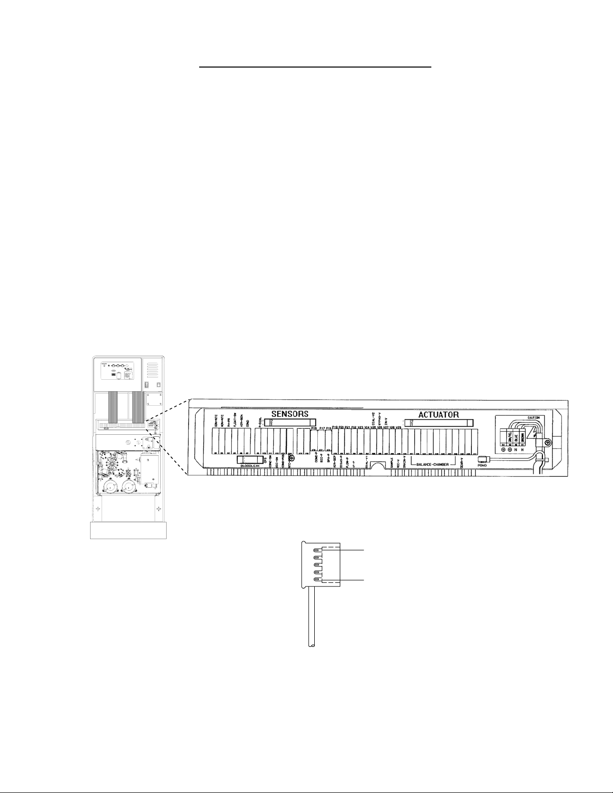
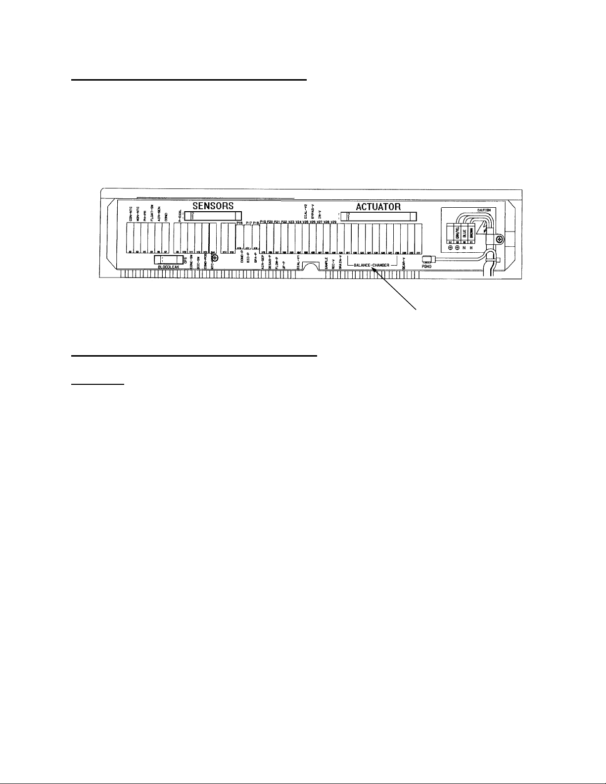
4. Most hydraulic components (valves, pumps, etc) can be checked at the DISTRIBUTION BOARD. Each
component has a numerically labeled connector ‘position’. Referring to the HYDRAULIC FLOW DIAGRAM
flow pump #21 plugs into position [P21, FLOW-P], valve 43 plugs into position [V43], etc.
NOTE: Except for the heater (CAUTION! High Voltage), sensor cable, actuator cable, acid pump, bicarbonate
pump or blood leak detector it is okay to unplug connectors with the power on.
CAUTION! Unplugging the sensor cable, actuator cable, acid pump, bicarbonate pump and the blood leak
detector with the power on may cause damage. Disconnecting the heater with the power on may cause
electrocution!
Figure 1 – Distribution Board
PIN 1
PIN 5
Figure 2 – Female Connector
5. If unsuccessful please call Technical Services at 1-800- 227- 2572.
Fresenius 2008K Troubleshooting Guide
P/N 507298 Rev. C
Page 1
Page 10

THE 'ORDER' OF TROUBLESHOOTING
Troubleshoot in the following order:
1. No Water
2. Flow Errors
3. Temperature
4. Conductivity
5. TMP
6. Blood Leak
7. Pressure Holding Test Failures
NOTE: Before beginning we recommend that you perform INITIAL CHECKS (page 3). This is especially
importa
1. A NO WATER alarm turns flow off. Clear NO WATER alarms before concerning yourself with other
2. Do not concern yourself with FLOW ERRORS if a NO WATER alarm is also present. Troubleshoot a NO
3. Do not concern yourself with a TEMPERATURE problem if a FLOW ERROR is also present. Flow errors
4. Do not concern yourself with CONDUCTIVITY problems if a TEMPERATURE problem is also present.
5. Do not concern yourself with a TMP problem if other hydraulic alarms (i.e. conductivity, temperature, flow)
6. Do not concern yourself with a BLOOD LEAK problem if other hydraulic alarms (i.e. conductivity,
CAUTION! Before placing the machine back into service always perform FINAL CHECKS (p
nt if someone has been working on the machine before you!
hydraulic alarms.
WATER alarm first and the FLOW ERROR will probably clear itself.
turn the heater off. Troubleshoot the FLOW ERROR first and the TEMPERATURE problem will probably
clear itself.
Conductivity is temperature compensated. Troubleshoot TEMPERATURE problems first and a
CONDUCTIVITY problem will probably clear itself.
are also present. Troubleshoot other hydraulic problems first and the TMP problem will probably clear.
temperature, flow) are also present. Troubleshoot other hydraulic problems first and the BLOOD LEAK
problem will probably clear.
age 4).
Page 2
Fresenius 2008K Troubleshooting Guide
P/N 507298 Rev. C
Page 11
INITIAL CHECKS
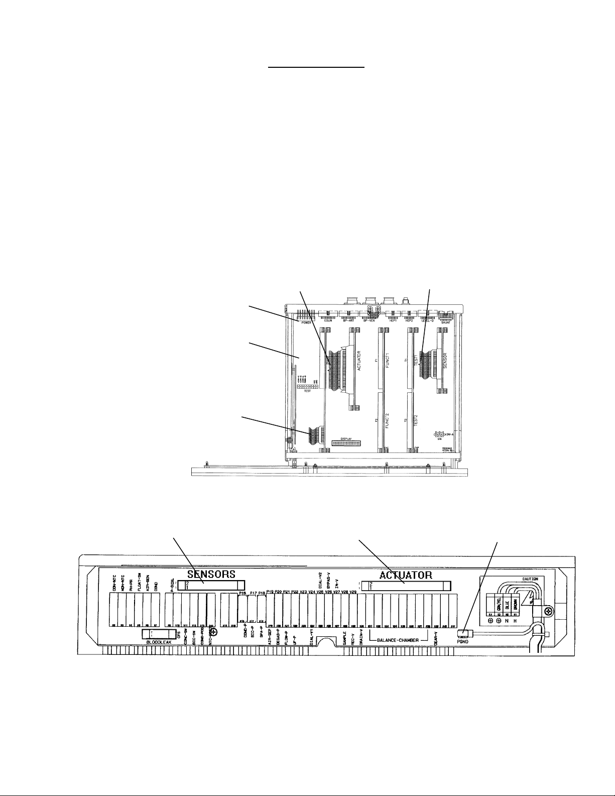
1. If the electronic card cage has been previously moved from the cabinet:
Check that all five boards are pushed down into the motherboard and locked in place.
Check that the power logic board cable is plugged in.
Check that the power cable is plugged into the power connector (see Figure 3 below).
Check that the sensor and actuator cables (see Figure 3 below) are plugged into the distribution board.
2.
Check that the PGND (power ground) wire is plugged into the distribution board (see Figure 4 below). A
3.
loose PGND cau
4. Check cables for worn insulation (bare wires) or other signs of damage (like screw holes). Replace if
damaged.
5. NEVER troubleshoot with the card cage open!
ses unpredictable symptoms.
ACTUATOR CABLE SENSOR CABLE
POWER CONNECTOR
MOTHER BOARD
POWER LOGIC
CABLE
Figure 3 – Card Cage (Top View)
SENSORS CONNECTOR ACTUATOR CONNECTOR PGND WIRE
Figure 4 – Distribution Board
Fresenius 2008K Troubleshooting Guide
P/N 507298 Rev. C
Page 3
Page 12
FINAL CHECKS
Before placing the machine back into service:
1. Remove all troubleshooting equipment (jumpers, 'dummy' connectors, etc) from the distribution board and
make sure that all hydraulic components are plugged in properly.
2. If you were troubleshooting FILLING PROGRAMS or FLOW ERRORS make sure that the female
connectors on chamber #69 are plugged in properly (brown wire on top).
3. Turn the heater breaker switch off. Allow eight minutes and assure that the Temperature display falls to
less than 30 and that the machine goes into bypass (valve #24 closes, no flow through the external
indicator).
4. Drop the acid and bicarbonate lines into water. Allow eight minutes and assure that the Conductivity
display falls to 10.0 mS/cm and that the machine goes into bypass (no flow through the external
indicator).
5. Check that AUDIO ALARMS are working properly.
6. IMPORTANT! Perform alarm and pressure holding tests. Do NOT place the machine back into service
until all tests have pass.
EQUIPMENT NEEDED
- Fresenius gauge kit (part # 150034)
- Fresenius test (temperature) 'dummy connectors' (part # 190060)
- 60 ml syringe
- Flashlight
- Jumper wire
- Independently calibrated temperature, conductivity, and pressure meters
- Voltmeter
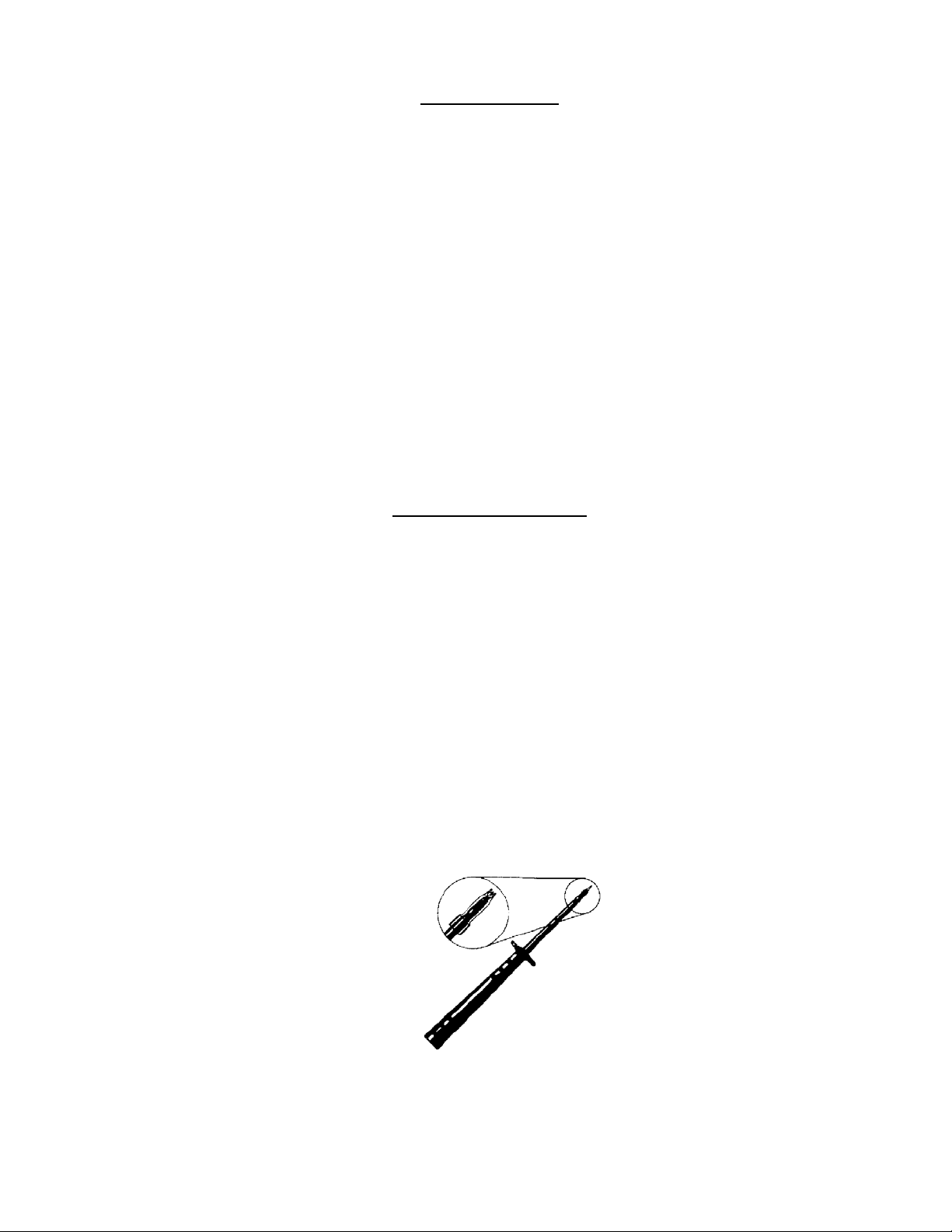
- Fluke TP80 meter probes. These probes have a slip-on cap that fits over the lead to 'isolate' the
measuring point and assures safe voltage measurements in ‘tight’ areas when shorting other pins or
connectors is a concern.
Page 4
Figure 5 - Fluke TP80 Meter Probes (with slip on cap)
Fresenius 2008K Troubleshooting Guide
P/N 507298 Rev. C
Page 13
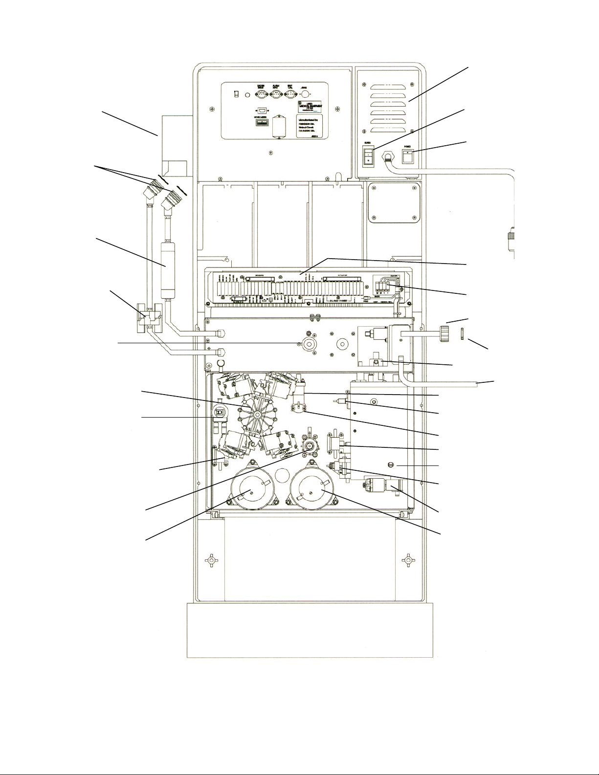
POWER SUPPLY
SHUNT DOOR
DIALYZER QUICK
CONNECTORS
EXTERNAL FLOW
INDICATOR #75
DIALYSATE LINE
FILTER #73
UF PUMP #22
BALANCING
CHAMBER #68
HEATER BREAKER
SWITCH
ON/OFF SWITCH
DISTRIBUTION BOARD
(INSIDE COVER)
HEATER
CONNECTOR
INPUT WATER
FILTER
FILTER
VENT LINE
DRAIN LINE
CONDUCTIVITY CELL #7
VALVE #25
Note: On Later version,
Valve 25 may be on the
front side of hydraulics
DIALYSATE PRESSURE
TRANSDUCER #9
REGULATOR #78
FLOW PUMP #21
NTC #2
NTC #3
CFS TRANSDUCER #10
ORIFICE #48
LOADING PRESSURE
REGULATOR #65
VALVE 39
DEAERATION PUMP #20
Figure 6 – Machine Rear View
Fresenius 2008K Troubleshooting Guide
P/N 507298 Rev. C
Page 5
Page 14

SECTION 1 - FLOW ERRORS IN DIALYZE MODE
F- 1.0.0 CHECK LOADING PRESSURE
a) Assure that the vent tubing (back of machine) is not 'pinched' (see Figure 6, page 5).
b)
Assure that dialysate flow is on (flow on/off LED off).
1
TIGHTLY insert a 2loading pressure gauge into the red ACETATE/ACID port. Proceed accordingly:
c)
0 to 10 psi. See F- 15.0.0, LOW LOADING PRESSURE (pa
ge 19).
10 to 17 psi. Calibrate loading pressure per CALIBRATION PROCEDURES. If
unsuccessful, the loading pressure regulator #65 (see Figure 6, page 5)
may be bad.
18 to 25 psi. See F- 2.0.0
Greater than 25 psi Calibrate loading pressure per CALIBRATION PROCEDURES. If
unsuccessful the loading pressure regulator #65 (see Figure 6, page 5)
may be bad.
1
If the gauge is not in the port correctly you will always read low pressure!
2
If the gauge does not read 0 psi at atmosphere compensate for this when reading it.
F- 2.0.0 CHECK DEBUG ERRORS (NO WATER AND FLOW ERROR)
a) Lift the shunt door to force bypass (bypass LED on). This should be done even if the machine is already in
bypass!
NOTE Unless instructed do NOT
try to reset alarms while troubleshooting flow errors.
b) Call debug screen 0. Intermittent problems are easily missed with a ‘quick look’ so watch for two minutes
or
until you see either a NO WATER alarm or a flow error (FLOW ERROR = “1”). Proceed accordingly:
NO WATER alarm (intermittent or constant). See SECTION 2 - NO WATER (p
age 24).
FLOW ERROR = “0” (constant). See F- 2.0.1
Page 6
FLOW ERROR = “1” (intermittent or constant). See F- 3.0.0
Fresenius 2008K Troubleshooting Guide
P/N 507298 Rev. C
Page 15

Section 1 – Flow Errors in Dialyze Mode
F- 2.0.1 FLOW ERROR NOT INDICATED (FLOW ERROR = “0”)
a) Leaving the shunt door open push the blue HOME screen button to return to the Home screen. Allow
Temperature and Conductivity to come out of alarm state.
NOTE: If the Temperature or Conductivity windows (in the main screen) are RED an alarm is present.
When alarms clear the windows turn yellow.
NOTE: Conductivity alarm limits can be adjusted: 1) Push the Conductivity data button to go to the
Dialysate screen. Select either Alarm Position or Alarm Width by pushing the appropriate blue
screen button 2) Adjust the limits using the UP or DOWN arrow keys. 3) Push the CONFIRM key.
4) Push the blue HOME screen button to return to the Home screen.
NOTE: If Temperature and Conductivity alarms do not clear and you are sure that FLOW ERROR = “0”
constant do NOT continue troubleshooting flow errors!
b) Close the shunt door. Assure that the machine is ‘out of bypass’ (bypass LED turns off). Is there flow
through the external flow indicator (is the bob rising)?
Yes See F- 2.0.2
See F- 14.0.0, TROUBLESHOOTING FLOW ERRORS ‘OUT OF B
No
F- 2.0.2 CHECK FLOW ERROR ‘OUT OF BYPASS’
YPASS’ (page 18).
Call debug screen 0. Intermittent problems are easily missed with a ‘quick look’ so watch FLOW ERROR for
five minutes
or until you see FLOW ERROR = “1”. Proceed accordingly:
FLOW ERROR = “0” (constant). Stop here! A flow error is not present.
FLOW ERROR = “1” (intermittent or constant). See F- 14.0.0, TROUBLESHOOTING FLOW
ERRORS ‘OUT OF BYPASS’ (page 18).
F- 3.0.0 CHECK FOR FILLING PROGRAM
Call debug screen 1. FILACT = "1"?
Yes Proceed to SECTION 8 - FILLING PROGRAM PROBLEMS (pag
e 64)
No See F- 4.0.0
F- 4.0.0 CHECK FOR A VALVE ERROR (VERR)
NOTE: Valve errors are caused by electrical current problems in a ‘valve circuit’. If present, VERR (debug
screen 1) increases (to a maximum of 255). If not present VERR remains 0.
Call debug screen 1. VERR is in the lower right corner. Is VERR = “0”?
Yes See F- 4.0.1
No
NOTE that you are in DIALYSIS program and proceed to TROUBLESHOOTING VALVE
ERRO
RS (page 31)
F- 4.0.1 CHECK FLOW ERROR “IN BYPASS”
Open the shunt door to cause bypass. Go to debug screen 0 and watch Flow Error for one minute. Does
Flow Error remain “0” constantly or does it still = “1” (either constant or intermittent)?
“0” constant See F- 2.0.2
Still = “1”
Close the shunt door and see F- 5.0.0
Fresenius 2008K Troubleshooting Guide
P/N 507298 Rev. C
Page 7
Page 16
Section 1 – Flow Errors in Dialyze Mode
F- 5.0.0 CHECK FOR A RUNNING FLOW MOTOR
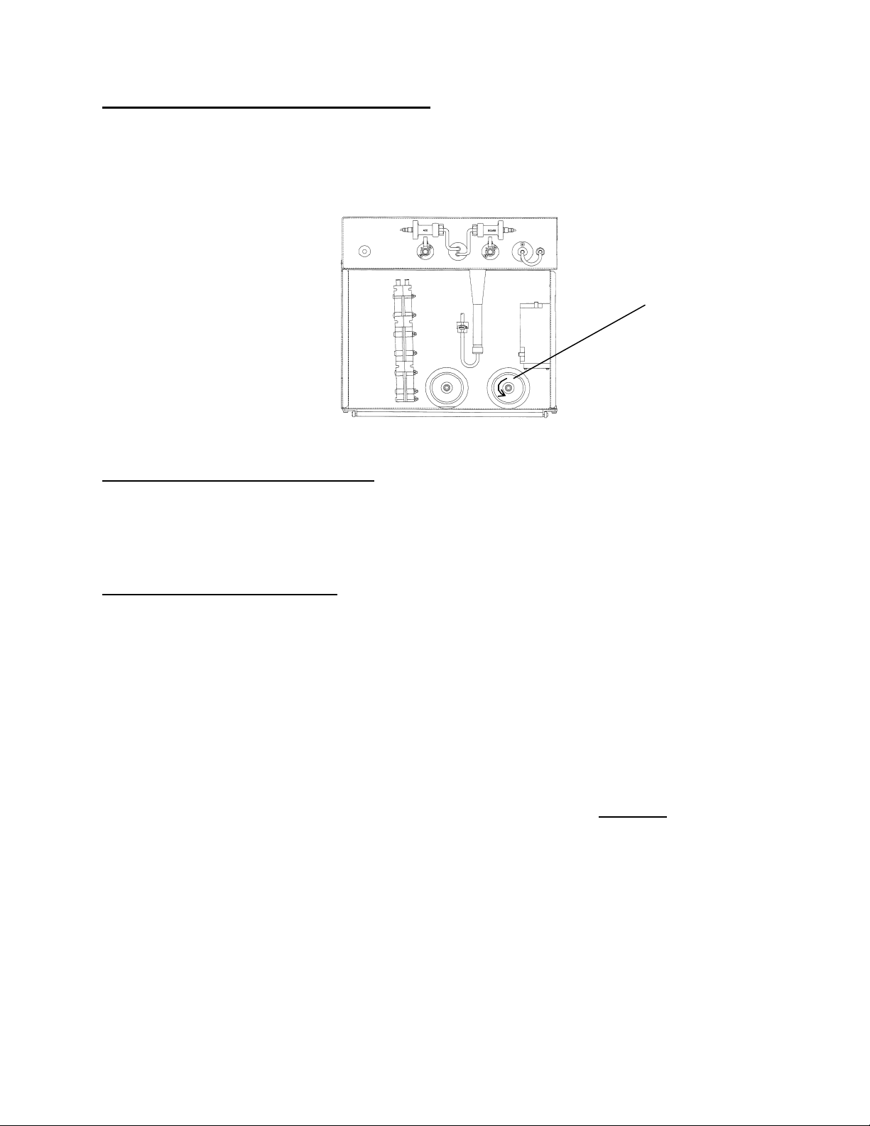
The flow pump’s motor shaft can be viewed from the front of the hydraulics (see Figure 7). Is the shaft
rotating count
er-clockwise (viewed from the FRONT!)?
Yes See F- 6.0.0
See TROUBLESHOOTING MOTORS (p
No
age 23) to check the FLOW MOTOR.
FLOW
MOTOR SHAFT
Figure 7 – Hydraulics (Front View)
F- 6.0.0 CHECK FLOW PUMP CONTROL
Turn dialysate flow off (flow on/off LED on) and check the flow pump's motor shaft again. Still rotating?
Yes Replace the actuator board (shorted driver).
No See F- 7.0.0
F- 7.0.0 DETERMINE DRAIN FLOW
Normal Fresenius flow 'pulses' in 30 ml (approximately) increments when the balancing chamber valves cycle
and ‘stops completely’ in between. Determine flow ‘type’ as defined below:
Normal: 30 ml - Stops completely - 30 ml - Stops completely – etc
Abnormal: Continuous flow (never stops, i.e. cannot distinguish 30 ml increments)
OR
30 ml – continuous – 30 ml – stops completely - etc
None: No drain output
a) IMPORTANT: Turn dialysate flow on (flow on/off LED off).
b) Go to end of the drain tubing. Hold the tubing so that the opening is pointed UPWARD!
(at about 45
degrees). CAUTION!! If the opening is held DOWNWARD this test is invalid.
c) Watch drain flow for 30 seconds. Proceed accordingly:
Normal: See F- 8.0.0 (page 12)
Abnorm
al or None: See F- 7.0.1
Page 8
Fresenius 2008K Troubleshooting Guide
P/N 507298 Rev. C
Page 17
Section 1 – Flow Errors in Dialyze Mode
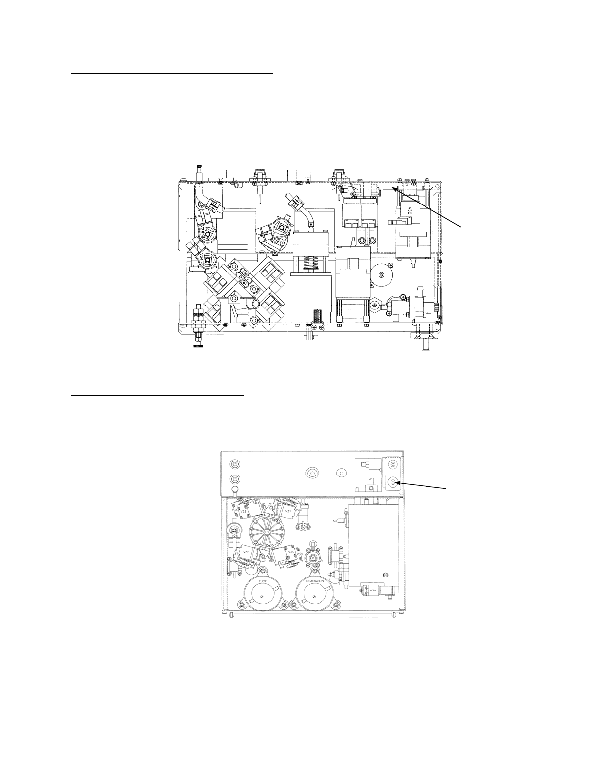
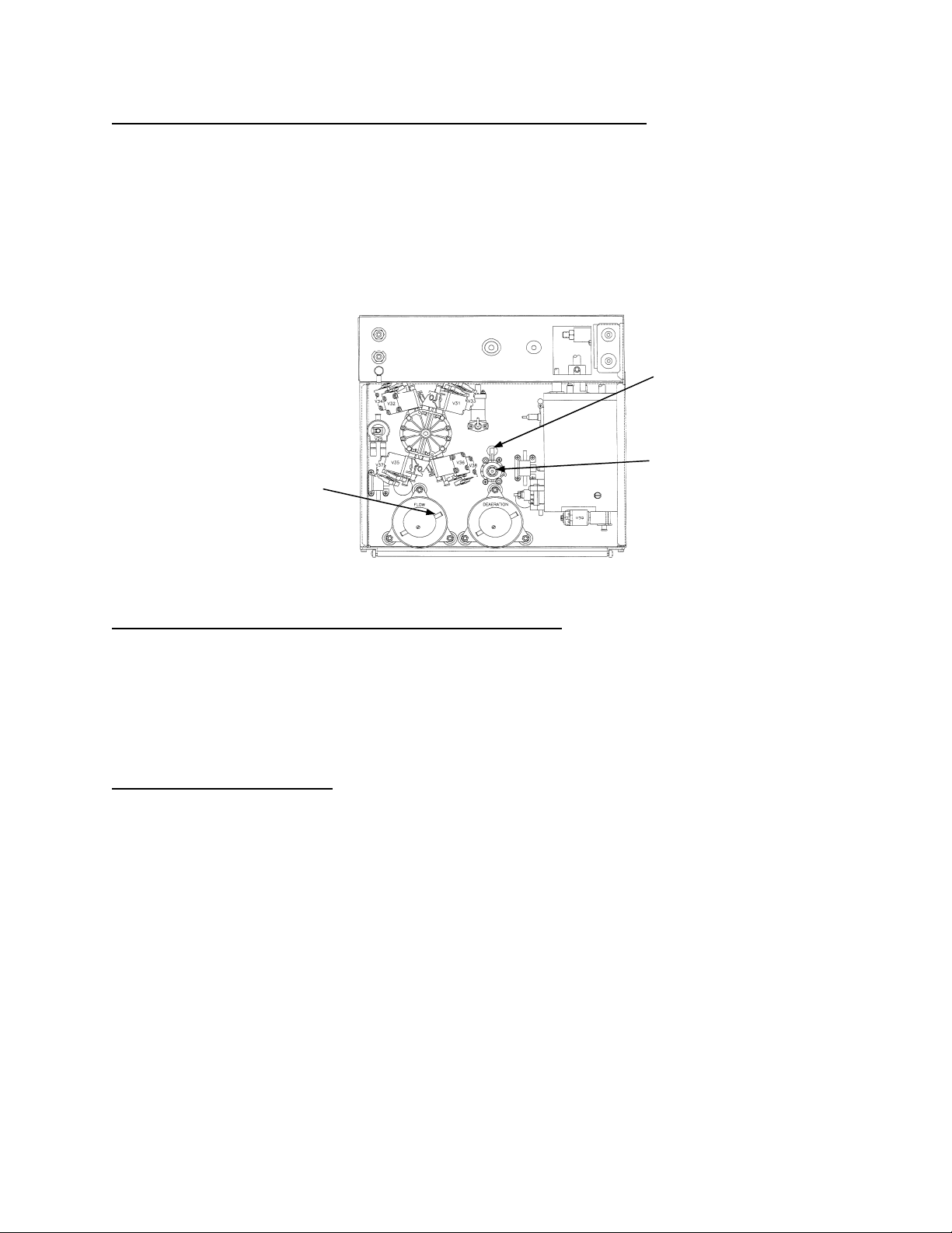
F- 7.0.1 CHECK (DRAIN) VALVE #30 INPUT
a) Turn dialysate flow off (flow on/off LED on) and remove (drain) valve 30’s INPUT tubing (see Figure 8).
Point the tubing’s o
utput AWAY from the hydraulics! Have a bucket ready to catch any output.
b) Turn dialysate flow on (flow on/off LED off). Proceed accordingly:
Normal: See F- 7.0.2
Abnorm
al or None: See F- 7.0.3
VALVE 30
INPUT
TUBING
Figure 8 – Hydraulics (Top View)
F- 7.0.2 CHECK VALVE #30 OUTPUT
a) Turn flow off (flow on/off LED on) and reconnect the tubing to valve 30.
b) Remove the tubing from bottom (drain) port at the rear of the machine (see Figure 9). Have a bucket ready
to c
atch any output.
Figure 9 - Hydraulics (Rear View)
Fresenius 2008K Troubleshooting Guide
P/N 507298 Rev. C
DRAIN PORT
Page 9
Page 18

Section 1 – Flow Errors in Dialyze Mode
c) Turn flow on (flow on/off LED off). Proceed accordingly:
Normal: The drain tubing or the drain itself is restricted. Locate and repair.
Abnormal or None: A problem is indicated with the actuator board or VALVE 30. NOTE this
and proceed to TROUBLESHOOTING VALVES (page 30).
F- 7.0.3 CHECK FILLING PROGRAM FUNCTION
a) Unplug the air sensor connector from distribution board position x6, AIR-SEN.
b) Wait 30 seconds and call debug screen 1. Does FILACT = “1”?
Yes A) Plug the connector back into the distribution board (position x6, AIR_SEN), allow
30 seconds, and assure that FILACT = “0”; B) See F– 7.0.4
No
Using a flashlight, check inside the distribution board for ‘white’ corrosion (indicative of
spillage). If no corrosion, two possibilities: 1) Bad sensor board; 2) Bad function board.
F- 7.0.4 CHECK ‘IN BYPASS’ FLOW
For this procedure a bucket 1/2 filled with water is needed.
a) Plug the acid and bicarbonate concentrate connectors into their ports. The screen returns to the SELECT
PROGRAM screen.
b) Reconnect the tubing to valve 30.
c) Place the machine into RINSE.
d) Open the shunt door (COVER OPEN message) and remove both quick connectors. Drop the RED quick
connector into the bucket. Hold the BLUE quick connector over the bucket such that the opening is held
UPWARD!
(at about 45 degrees). CAUTION!! If the opening is held DOWNWARD this test is invalid.
e) IMPORTANT leave the shunt door open!
f) Watch flow here for 30 seconds and NOTE flow ‘type’ (Normal, Abnormal, None) for later use. Proceed to
step F- 7.0.5
®
F- 7.0.5 DETERMINING DIASAFE
The DIASAFE
®
filter looks like a dialyzer that is mounted in the bottom compartment under the hydraulics.
FILTER
Also, there is a ‘test valve’ on the rear panel.
a) Unplug the acid connector from its port to INTERRUPT rinse then plug it back in.
b) Place the quick connectors back into the shunt and close the door.
®
c) Does this machine have a DIASAFE
filter?
Yes See F- 7.0.6
No
See F- 7.0.8
Page 10
Fresenius 2008K Troubleshooting Guide
P/N 507298 Rev. C
Page 19

Section 1 – Flow Errors in Dialyze Mode
®
F- 7.0.6 CHECK THE DIASAFE
a) If the DIASAFE
®
filter and its quick connector o-rings have not been replaced in the last 90 days do so now
and see F- 7.0.7. If it has been repla
FILTER
ced see part b.
b) Assure that the ‘test valve’ is set in DIALYZE position. If not, set it there, and see F– 7.0.7. If already in
DIALYZE position see p
c) Check for tubing restrictions at the DIASAFE
art c
®
filter. Clear all restrictions and see F- 7.0.7. If not restricted
see step F- 7.0.8
F- 7.0.7 TROUBLESHOOTING THE DIASAFE
®
FILTER
a) Return to the SELECT PROGRAM screen by reconnecting the acid and bicarbonate concentrate
connectors to their ports on the front of the machine.
b) Place the machine into RINSE for three minutes.
c) Remove the acid and bicarbonate concentrate connectors from their ports and plug them back into
concentrate.
®
d) If the DIASAFE
F- 7.0.8 DETERMINE FLOW PROBLEM
As noted, in step F- 7.0.4 a
filter was the problem the flow error will clear. Return to step F- 2.0.0.
bove, was flow through the BLUE quick connector:
Normal: A problem is indicated with the actuator board or VALVE 26. NOTE this and proceed
to TROUBLESHOOTING VALVES (page 30).
Abnorm
None: Possibly two balancing chamber valves stuck closed! Try replacing the actuator
al: See F- 7.0.9
board.
F- 7.0.9 CHECK BALANCING CHAMBER VALVES AND BALANCING
CHAMBER DIAPHRAGM
Perform SECTION 18 - MANUAL BALANCING CHAMBER VALVE LEAK TESTS (page 92) on the balancing
cham
ber valves (V31 through V38). Did the leak test indicate a leaking valve?
Yes See F- 7.1.1
Possible leaking balancing chamber diaphragm. Perform SECTION 19 - TESTING FOR A
No
LEAKING BALANCI
NG CHAMBER DIAPHRAGM (page 96).
Fresenius 2008K Troubleshooting Guide
Page 11
P/N 507298 Rev. C
Page 20
Section 1 – Flow Errors in Dialyze Mode
F- 7.1.1 CHECK FOR A SHORTED VALVE DRIVER
a) Unplug the indicated leaking valve from the distribution board (see Figure 10 below). Using a flashlight,
che
ck inside the distribution board, for ‘white corrosion’ (indicative of spillage).
b) If no corrosion: measure volts dc, inside the distribution board, BETWEEN male pins 1 and 5 (top and
bottom). Place the red lead at pin 5 (bottom). Greater than one volt?
Yes Replace the actuator board (shorted driver).
No Replace the indicated leaking balancing chamber valve.
BALANCING CHAMBER
VALVE POSITIONS
Figure 10 – Distribution Board
F- 8.0.0 CHECK CFS TRANSDUCER SIGNAL (ACFS)
Call debug screen 0. Intermittent problems are easily missed with a ‘quick look’ so watch ACFS (in volts) for
two minutes
or until you have determined the symptom. Proceed accordingly:
ACFS remaining between 3.0 and 7.0. See F- 9.0.0 (page 13)
ACFS remaining between 7.0 and 12. See F- 10.0.0 (page 14*)
ACFS remaining between 0 and 3.0. See F- 11.0.0 (page 14)
ACFS cycling from about 4 (4.0 to 5.5) to about 2 (0 to 3.0). See F- 13.0.0 (p
ACFS intermittently going to between 7 and 12. See F- 10.0.0 (pa
ge 14)
age 17).
Page 12
Fresenius 2008K Troubleshooting Guide
P/N 507298 Rev. C
Page 21
Section 1 – Flow Errors in Dialyze Mode
F- 9.0.0 ACFS BETWEEN 3.0 AND 7.0 - CHE
CK FLOW PUMP PRESSURE
The CFS signal is not switching the balancing chambers properly.
a) Turn dialysate flow off and tee a psi gauge between the flow pump's output nozzle and the WHITE tubing
(see Figure 11 below, for gauge location).
Turn the dialysate flow on (flow on/off LED off) and set to 500 ml/min. Does pressure peak to 14 psi or
b)
greater?
Yes See F- 9.0.2
See F- 9.0.1
No
CLAMP HERE
REGULATOR #78
FLOW PUMP
OUTPUT
Figure 11 - Hydraulics (Rear View)
F- 9.0.1 CHECK FLOW RELIEF PRESSURE REGULATOR #78
With a metal hemostat TIGHTLY clamp regulator #78 at the location specified in the Figure 11 above. Does
flow pump p
F- 9.0.2 CHECK CFS CIRCUIT
a) Unplug the CFS transducer from distribution board position CFS. Using a flashlight, check inside the
distribution board, for ‘white’ corrosion (indicative of spillage).
b) If no corrosion: inside the distribution board there should be five male pins. Check for bent or broken male
pins.
c) If all pins are okay: is ACFS between 7.0 and 10?
ressure peak to 14 psi or greater now?
Yes Calibrate FLOW RELIEF PRESSURE per CALIBRATION PROCEDURES. If unsuccessful
regulator #78 may be malfunctioning.
No Three possibilities: 1) Bad actuator board; 2) Bad flow pump head; 3) Bad flow pump motor
Yes See F- 9.0.3
See F- 12.0.0 (page 16)
No
Fresenius 2008K Troubleshooting Guide
P/N 507298 Rev. C
Page 13
Page 22

Section 1 – Flow Errors in Dialyze Mode
F- 9.0.3 CHECK SENSOR BOARD CABLE
a) Plug the CFS transducer back into the distribution board.
If ACFS remains between 7 and 10 make sure that you have plugged in properly.
If ACFS starts cycling from about 4 (4.0 to 5.5) to about 2 (0 to 3.0) and if the flow error is still
present return to F- 2.0.0
b)
Have you tried calibrating FLOW RELIEF PRESSURE during this troubleshooting session?
Yes Three possibilities: 1) Bad CFS transducer (see Figure 6, page 5); 2) Bad flow pump head;
3) Bad flow m
otor (try new brushes)
No Try calibration FLOW RELIEF PRESSURE per CALIBRATION PROCEDURES and return to
F- 2.0.0. If F
F- 10.0.0 ACFS BETWEEN 7.0 AND 10 – CHECK CFS CIRCUIT
LOW RELIEF PRESSURE was the problem, the flow error will clear.
The CFS transducer is acting ‘open’.
a) Unplug the CFS transducer from distribution board position CFS. Using a flashlight, check inside the
distribution board connector for ‘white’ corrosion (indicative of spillage).
b) If no corrosion: inside the distribution board there should be five male pins. Check for bent or broken
male pins.
c) If all pins are okay: plug the 34degree temperature ‘dummy connector’ into distribution board position CFS
(this simulates a good transducer). From debug screen 0, does ACFS go to 0?
Yes See F- 10.0.1
Possible: 1)
No
1
The sensor board cable can be checked for continuity. Note that you are checking CFS TRANSDUCER
connections and proceed to SECTION 17 - CHECKING SENSOR BOARD CABLE (pag
F- 10.0.1 CHECK CFS TRANSDUCER
1
Bad sensor board cable; 2) Bad sensor board; 3) Bad actuator board
e 90).
Plug the CFS transducer back into the distribution board. Does ACFS start cycling from about 4 (4.0 to 5.5)
to about 2 (0 to 3.0)?
Yes The CFS transducer seems to be working okay. Return to F- 2.0.0 but if you return he
re
replace the CFS transducer (see Figure 6, page 5)
Bad CFS transducer (see Figure 6, page 5).
No
F- 11.0.0 ACFS BETWEEN 0 AND 3.0 – CHECK FLOW PUMP ‘DEAD HEAD’
The CFS transducer is acting ‘shorted’.
Turn dialysate flow off (flow on/off LED on). Is ACFS between 4.0 and 7.0?
Yes The CFS transducer is good! Return to F- 2.0.0.
No
See F- 11.0.1
Page 14
Fresenius 2008K Troubleshooting Guide
P/N 507298 Rev. C
Page 23

Section 1 – Flow Errors in Dialyze Mode
F- 11.0.1 CHECK CFS CIRCUIT
a) Unplug the CFS transducer from distribution board position CFS. Using a flashlight, check inside the
distribution board for ‘white’ corrosion (indicative of spillage).
b) If corrosion not present: Inside the distribution board there should be five male pins. Check for bent or
broken male pins.
c) If all five pins are okay: is ACFS between 7.0 and 10?
Yes See F- 11.0.3
See F- 12.0.0
No
F- 11.0.3 CHECK FOR A LEAKING BALANCING CHAMBER VALVE
a) Plug the CFS transducer back into the distribution board. If ACFS remains between 7 and 12 make sure
that you have plugged the transducer in properly.
b) Turn dialysate flow on (flow on/off LED off).
c) Push the blue HOME screen button to return to the main dialysis screen. Does the digital TMP reading
have positive (+) sign (example +220 mmHg)?
Yes See F- 11.0.4
Replace the CFS transducer (see Figure 6, page 5).
No
NOTE: TMP readin
gs with no sign (example 220 mmHg) indicates that venous pressure is greater than
dialysate pressure. If TMP readings have a positive sign (example +220 mmHg) dialysate pressure is greater
than venous pressure.
F- 11.0.4 CHECK FOR (+) POSITIVE TMP
a) Push and release the RESET key. The message "RESET TO ADJUST TMP" appears.
b) Immediately push and HOLD the RESET key. After the "ADJUSTING TMP" message is gone does TMP
return to a positive (+) value or remain relatively stable?
Returns positive (+) See F- 11.0.5
ns stable Replace the CFS transducer (see Figure 6, page 5).
Remai
F- 11.0.5 CHECKING BALANCING CHAMBER VALVES
Perform SECTION 18 - MANUAL BALANCING CHAMBER VALVE LEAK TESTS (page 92) on the balancing
cham
ber valves (V31 through V38). Did the leak test indicate a leaking valve?
Yes See F- 11.0.6.
Replace the CFS transducer (see Figure 6, page 5).
No
Fresenius 2008K Troubleshooting Guide
P/N 507298 Rev. C
Page 15
Page 24
Section 1 – Flow Errors in Dialyze Mode
F- 11.0.6 CHECK FOR A SHORTED VALVE DRIVER
Remain in DIAGNOSTICS for this procedure.
a) Unplug the NOTED leaking balancing chamber valve from the distribution board. Using a flashlight, check
inside the distribution board for ‘white’ corrosion (indicative of spillage).
b) Measure volts dc, inside the distribution board, BETWEEN male pins 1 (top) and 5 (bottom). Place the
meter’s red lead at pin 5. Greater than one volt?
Yes Replace the actuator board (shorted driver).
No Replace the NOTED leaking balancing chamber valve
F- 12.0.0 CHECK SENSOR BOARD CABLE
a) Turn the power off, slide the electronic card cage out, and unplug the sensor board’s ribbon cable (see
Figure 3, page 3).
b)
Check, inside the sensor board connector, for bent or broken male pins.
c) If pins are okay: leaving the cable unplugged, turn the power on.
d) Return to debug screen 0. Ignore all alarms! Is ACFS between 7.0 and 10?
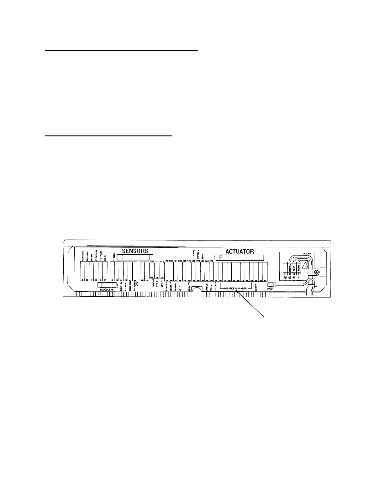
Yes A) Unplug the sensor board ribbon cable from the distribution board SENSORS connector
(see Figure 12 below); B) Using a flashlight, che
ck inside the distribution board’s SENSORS
connector for ‘white’ corrosion (indicative of spillage) and for bent or broken male pins; C) If
no corrosion and all pins are okay: replace the sensor board ribbon cable.
No Possible: 1) Bad sensor board; 2) Bad actuator board.
Page 16
Figure 12 – Distribution Board
Fresenius 2008K Troubleshooting Guide
P/N 507298 Rev. C
BALANCING CHAMBER
VALVE POSITIONS
Page 25

Section 1 – Flow Errors in Dialyze Mode
Figure 13 - Hydraulics (Rear View)
F- 13.0.0 ACFS CYCLING - CHECK BALANCING CHAMBER VALVES (STUCK CLOSED)
a) Assure that all balancing chamber valves are plugged into the distribution board at their proper position (see
Figure 12, page 16 and Figure 13 above).
b)
IMPORTANT: Set dialysate flow rate to 500 ml/min.
NOTE: Flow errors caused by a balancing chamber valve not opening are predictably cyclic.
c) Call debug screen 0 and watch ACFS for one minute
where it remains for 3 seconds to about 2 volts (0 to 2.8 volts) where it remains for ten seconds?
Yes A balancing chamber valve is not opening. See F- 13.0.1
No
F- 13.0.1 CHECK THE ACTUATOR BOARD
Return to step F- 2.0.0
Have you already tried replacing the actuator board during this troubleshooting session?
Yes See F- 13.0.2
No
Try replacing the actuator board and return to F- 2.0.0.
the flow error will clear.
. Is ACFS cycling from about 4 volts (4.0 to 5.5 volts)
If the actuator board is the problem
Fresenius 2008K Troubleshooting Guide
P/N 507298 Rev. C
Page 17
Page 26

Section 1 – Flow Errors in Dialyze Mode
F- 13.0.2 TROUBLESHOOTING A ‘MECHANICALLY’ CLOSED BALANCING CHAMBER VALVE
a) Using a metal hemostat tightly clamp balancing chamber valve #35 as close to the valve as you can. From
the rear valve #35 is in the lower, left side (see Figure 13, page 17).
b)
Wait 30 seconds. From debug screen 0 does ACFS remain between 0 and 2.8 and FLOW ERROR = “1”
constant?
Yes Valve #33 or #34 or #37 or #38 is not opening.
No Flow Error remains intermittent: Valve #31 or #32 or #35 or #36 is not opening.
F- 14.0.0 TROUBLESHOOTING FLOW ERRORS 'OUT OF BYPASS'
A restriction is indicated in the 'out of bypass' circuit, which includes the *DIASAFE
®
filter (if present), external
dialysate filter #73, valve #24 and valve #25.
®
*The DIASAFE
filter looks like a dialyzer that is mounted in the bottom compartment under the hydraulics.
Also, there is a ‘test valve’ on the rear panel
Normal Fresenius flow pulses in 30 ml (±1ml) increments when the balancing chamber valves cycle and
‘stops completely’ in between. During the following procedure determine flow ‘type’ as defined below:
Normal: 30 ml - Stops completely - 30 ml - Stops completely – etc
Abnormal: Continuous flow (never stops, i.e. cannot distinguish 30 ml increments)
None: No output
®
F- 14.0.1 CHECK V24 AND THE DIASAFE
FILTER (IF PRESENT)
a) Plug the acid and bicarbonate concentrate connectors into their ports. The machine returns to the SELECT
PROGRAM screen.
b) Place the machine into RINSE. Have a bucket ready to catch any output.
c) With a bucket ready to catch any output, open the shunt door (COVER OPEN message) and remove the
RED quick connector.
d) IMPORTANT Leave the door open! There should be flow through the shunt door port. Proceed accordingly:
®
Normal: See F- 14.0.2 (valve #24 and the DIASAFE
filter (if present) are okay)
Abnormal or None: See F- 14.0.3
F- 14.0.2 CHECK EXTERNAL DIALYSATE FILTER #73
a) Unplug the acid connector from its port to INTERRUPT rinse then plug it back in.
b) Place the quick connectors back into the shunt and close the door.
c) Check the external dialysate filter #73 (see Figure 6, page 5) for restrictions.
If filter #73 is okay: a problem is indicated with the actuator board or VALVE 25. NOTE this and proceed to
d)
TROUBLESHOOTING VALVES (page 30).
Page 18
Fresenius 2008K Troubleshooting Guide
P/N 507298 Rev. C
Page 27

Section 1 – Flow Errors in Dialyze Mode
®
F- 14.0.3 CHECK V24 AND THE DIASAFE
FILTER
a) Unplug the acid connector from its port to INTERRUPT rinse then plug it back in.
b) Place the quick connectors back into the shunt and close the door.
®
c) Does this machine have the DIASAFE
filter?
Yes See F- 14.0.4
No
A problem is indicated with the actuator board, actuator cable, or VALVE 24. NOTE this and
proceed to TROUBLESHOOTING VALVES (page 30).
F- 14.0.4 CHECK DIASAFE
a) If the DIASAFE
®
filter and its quick connector o-rings have not been replaced in the last 90 days do so now
and see F- 14.0.5. If
®
FILTER
it has been replaced, proceed to part b.
b) Assure that the ‘test valve’ is set in DIALYZE position. If not set it there and see F- 14.0.5. If already set i
DIALYZE position proceed to part c.
®
c) Check for tubing restrictions at the DIASAFE
filter. Clear all restrictions and see F- 14.0.5. If not restricted
proceed to part d.
d) A problem is indicated with the actuator board or VALVE 24. NOTE this and proceed to
TROUBLESHOOTING VALVES (page 30).
®
F- 14.0.5 TROUBLESHOOTING THE DIASAFE
FILTER
a) Return to the SELECT PROGRAM screen by reconnecting the acid and bicarbonate concentrate
connectors to their ports on the front of the machine.
b) Place the machine into RINSE for three minutes.
c) Remove the acid and bicarbonate concentrate connectors from their ports and plug them back into
concentrate.
®
d) If the DIASAFE
F- 15.0.0 LOADING PRESSURE LOW (0 to 10 psi) /CHECK DEAERATION PUMP
filter was the problem the flow error will clear. Return to step F- 2.0.0.
The deaeration pump's motor shaft can be viewed from the front of the hydraulics (see Figure 14, page 20).
Is
the shaft rotating counter-clockwise (from the FRONT!)?
n
Yes See F- 15.0.1
See TROUBLESHOOTING MOTORS (p
No
age 23) to check the DEAERATION MOTOR.
Fresenius 2008K Troubleshooting Guide
Page 19
P/N 507298 Rev. C
Page 28
Section 1 – Flow Errors in Dialyze Mode
FLOW
MOTOR SHAFT
HYDRAULICS (FRONT VIEW) HYDRAULICS (REAR VIEW)
Figure 14
F- 15.0.1 LOADING PRESSURE LOW - DEAERATION MOTOR RUNNING
NOTE: This procedure checks for water in the hydro block.
a) Turn flow off (flow on/off LED on). Call debug screen 0 and wait until DEAP = 255 (indicates deaeration
motor is off).
b) Remove the CLEAR (input) tubing from the deaeration pump's nozzle (see Figure 14 above). Hold it below
the pump. Is there continu
ous (never stops) flow from this tubing?
Yes See F- 15.0.2
See F- 15.0.5
No
F- 15.0.2 CHECK INCOMING WATER
a) Allow flow to continue from the tubing (use a bucket to catch it).
b) Call debug screen 0. When the float’s bob drops, incoming water valve #41 is energized open. This is
indicated when the circle (next to the valve) turns solid blue. Normally (if the incoming water circuit is okay)
valve #41 will open for about one second per cycle.
c) Intermittent water problems are missed with a ‘quick look’. Watch specifically (and carefully) for a NO
WATER alarm for two minutes
Yes Reconnect the tubing to the deaeration pump and see SECTION 2 - NO WATER (pa
. Is a NO WATER alarm ever present?
ge 24).
No See F- 15.0.3
F- 15.0.3 RECHECK LOADING PRESSURE
a) Reconnect the tubing and turn flow on (flow on/off LED off).
b) Wait 30 seconds. Does loading pressure return to normal (18 to 25 psi)?
Yes Problem maybe solved. If low loading pressure symptoms repeat: 1) Possible bad deaeration
pump head; 2) Possible bad deaeration motor (try brushes); 3) Possible bad (intermittent)
float switch; 4) Possible stripped orifice fitting or bad orifice o-rings.
No See F- 15.0.4
Page 20
Fresenius 2008K Troubleshooting Guide
P/N 507298 Rev. C
Page 29
Section 1 – Flow Errors in Dialyze Mode
F- 15.0.4 CHECK DEAERATION PUMP AND LOADING PRESSURE REGULATOR
While watching the loading pressure gauge, tightly clamp the white tubing between the loading pressure
regulator #65 and the hydroblock (see Figure 15 below). Does loading pressure increase to greater than
20 psi
?
Yes The loading pressure regulator #65 (see Figure 15 below) is bad.
Two possibilities: 1) Deaeration pump head; 2) Deaeration motor brushes (see brush
No
replacement process in the PREVENTATIVE MAINTENANCE manual).
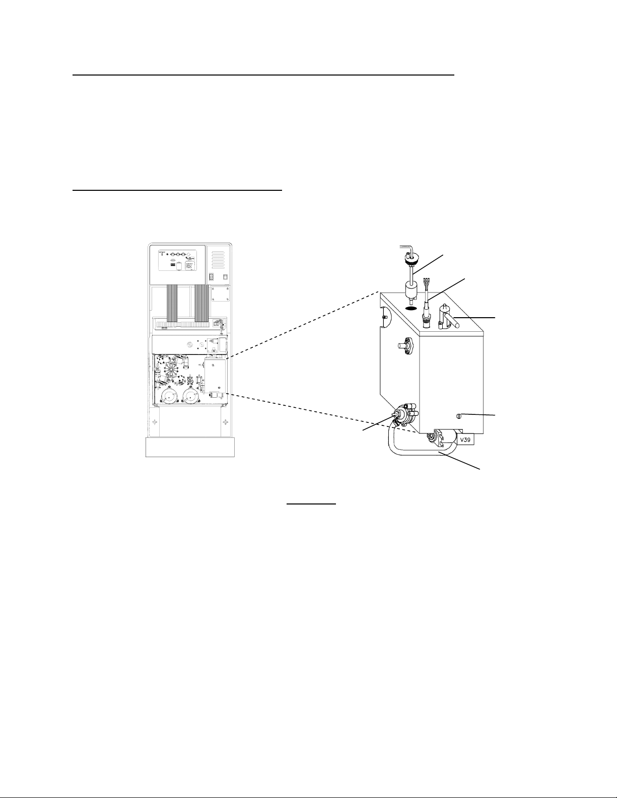
F- 15.0.5 CHECK THE ORIFICE AND FLOAT
a) Reconnect the tubing and turn the water OFF.
b) Clamp the hydro block vent tube (see Figure 15 below). Unscrew and pull the o
block (see Figure 15 below). If the small opening, at the end of the shaft, is plugged thi
rifice (#48) from the hydro
s is the problem!
FLOAT (FULLY DOWN ON SHAFT)
HEATER
VENT TUBE
ORIFICE (#48)
LOADING PRESSURE
REGULATOR #65
Figure 15 – Hydroblock
SOLID TUBING
(CLAMP HERE,
Step F- 15.0.4)
c) Re-install the orifice (don’t over tighten!) and UNCLAMP the vent tube.
d) Remove the float (see Figure 15 above). CAU
TION! Don't pull on the wiring harness!
e) Holding the float FULLY UP turn the water ON.
f) CAUTION Avoid overflow during this step! Looking into the hydro block’s float cavity move the float bob
FULLY DOWN. Is the water level rising?
Yes a) Turn the water off and reinstall the float; b) Turn the water on and see F- 15.0.7
See F- 15.0.6
No
Fresenius 2008K Troubleshooting Guide
P/N 507298 Rev. C
Page 21
Page 30

Section 1 – Flow Errors in Dialyze Mode
F- 15.0.6 CHECK THE FLOAT CIRCUIT
a) Turn the water off.
b) Unplug the float from distribution board position FLOAT-SW. Using a flashlight, check inside the distribution
board for ‘white’ corrosion (indicative of spillage).
c) If no corrosion: inside the distribution board there should be five male pins. Check for bent or broken
male pins.
d) If all pins are okay: place a jumper wire, inside the distribution board, BETWEEN male pins 1 and 3 (top
and middle). This simulates a ‘closed’ float switch. IMPORTANT! Make VERY sure of a good jumper
connection!
e) Call debug screen 0. Is the circle next to valve #41 solid blue (indicating valve #41 is energized)?
Yes The float is bad. Replace it and see F 15.0.7
No
Two possibilities: 1) *Bad sensor board cable; 2) Bad actuator board.
*The sensor cable can be checked for continuity. Note that you are checking the FLOAT connection and see
SECTION 17 - CHECKING SENSOR BOARD CABLE (page 90).
F- 15.0.7 CLEARING AN AIR LOCK
There should be flow through the hydro block unless an air lock is present.
a) Assure that the water in ON.
b) Connect a 60 ml syringe (with plunger) to the deaeration pumps clear INLET tubing and draw on the
plunger. You may have to pull several syringes full of air before you achieve continuous flow. If unable to
achieve continuous flow (after five or six tries) the orifice fitting may be 'stripped'.
c) Reconnect the tubing to the deaeration pump nozzle and turn flow on.
d) Allow loading pressure to return to normal (18 to 25 psi).
NOTE: Recurring air locks may be indicative a 'stripped' orifice fitting, bad orifice o-rings or bad (intermittent)
float switch.
Page 22
Fresenius 2008K Troubleshooting Guide
P/N 507298 Rev. C
Page 31

Section 1 – Flow Errors in Dialyze Mode
TROUBLESHOOTING MOTORS
IMPORTANT! Proceed ONLY with the NOTED motor.
NOTE: If the motor shaft is turning but clockwise (when viewed from the motor end!) someone has misaligned
the housing and motor cap. This can be corrected by turning the motor cap 180 degrees from its present
location (see DEAERATION MOTOR BRUSHES in the PREVENTATIVE MAINTENANCE manual).
a) Assure that the NOTED motor is plugged into the correct distribution board position (see Table 1 below).
Wiggle the female distribution board connector and check if the motor starts rotating. If so there may be a
b)
bad connection inside the female connector.
c) Tap the motor with a screwdriver and check if the motor starts rotating. If so the brushes need replacing.
d) Assure that dialysate flow is on and set at the rate as directed in Table 1 below.
Unplug the motor from its distribution board position. Using a flashlight check inside the distribution board
e)
for ‘white’ corrosion (indicative of spillage).
f) If no corrosion: inside the distribution board there should be five male pins. Check for bent or broken
male pins.
g) If all pins are okay: set your meter to DC voltage and clip the leads, inside the distribution board, BETWEEN
pins 1 and 5 (top and bottom). IMPORTANT! Make certain of good meter connections. Place the red
male
meter lead at pin 1 (top pin). Follow the directions given in Table 1.
Table 1 – Motor Troubleshooting
DISTRIBUTION
PUMP
BOARD
POSITION
DEAERATION P20, DEGAS-P 500
FLOW P21, FLOW-P 800
1
The actuator cable can be checked for continuity. Note that you are checking DEAERATION MOTOR
connections and see SECTION 16 - CHECKING ACTUATOR BOARD
2
The actuator cable can be checked for continuity. Note that you are checking FLOW MOTOR connections
and see SECTION 16 - CHECKING ACTUATOR BOARD
FLOW
RATE
(ml/min)
VOLTAGE
RANGE
BAD
16 vdc or greater Replace the pump head
Two Possibilities:
1
Less than 16 vdc
Actuator cable
1.
2. Actuator board
12 vdc or greater Replace the pump head
Two Possibilities:
Less than 12 vdc
2
1.
Actuator cable
2. Actuator board
CABLE (page 88).
CABLE (page 88).
Fresenius 2008K Troubleshooting Guide
P/N 507298 Rev. C
Page 23
Page 32

SECTION 2 - NO WATER
NW- 1.0.0 CHECK INCOMING WATER SYSTEM
a) Assure that the water is ON!
b) Assure that the vent tubing (back of machine) is not 'pinched' (see Figure 6, page 5).
c)
Turn the water off and check the input water filter (if present) for restrictions (see Figure 6, page 5).
Before hooking the incoming water line back up assure that there is adequate incoming water flow
d)
(1 liter/min or greater).
e) Tee a pressure gauge at the output side of pressure regulator #61 (see Figure 16 below for location).
Turn the water on. Is gauge reading 18 psi or greater?
f)
Yes Leave the gauge in place and see NW- 2.0.0
Calibrate INLET WATER PRESSURE per CALIBRATION PROCEDURES. If unsuccessful a
No
bad pressure regulator #61 is indicated.
VALVE #41
PLACE GAUGE HERE
REGULATOR #61
Figure 16 – Hydraulics (Top View)
Page 24
Fresenius 2008K Troubleshooting Guide
P/N 507298 Rev. C
Page 33

Section 2 – No Water
NW- 2.0.0 CHECK FLOAT SIGNAL
a) Turn the water off.
b) Unplug the float connector from distribution board position x5, FLOAT-SW. Using a flashlight, check inside
the distribution board for ‘white’ corrosion (indicative of spillage).
c) If no corrosion: inside the distribution board there should be five male pins. Check for bent or broken
male pins.
d) If all pins are okay: place a jumper wire, inside the distribution board, BETWEEN male pins 1 and 3 (top
and middle). This simulates a ‘closed’ float switch. IMPORTANT! Make VERY sure of a good jumper
connection!
e) Call debug screen 0. Is the circle next to valve #41 solid blue (indicating valve #41 is energized)?
Yes Leave the jumper in place and see NW- 2.0.1
No
Two possibilities: 1) *Bad sensor board cable; 2) Bad actuator board.
*The sensor cable can be checked for continuity. Note that you are checking the FLOAT connection and
proceed to SECTION 17 - CHECKING SENSOR BOARD CABLE (pag
NW- 2.0.1 CHECK VALVE #41
e 90).
Does the gauge at regulator #61 indicate low pressure (about 0 psi)?
Yes Bad float
No See NW- 3.0.0 (valve #41 i
s not opening)
NW- 3.0.0 CHECK FOR VALVE ERROR (VERR) AT VALVE #41
NOTE: Valve errors are caused by electrical current problems in a ‘valve circuit’. If present, VERR (debug
screen 1) increases (to a maximum of 255). If not present VERR remains 0. VERR is in the lower right
corner of screen 1.
a) IMPORTANT. Turn the power off and then back on.
b) Place the machine into DIALYSIS program and QUICKLY enter debug screen 1. Is VERR increasing?
Yes A) Plug the float back into the distribution board (position x5, FLOAT-SW); B) Turn the water
on; C) NOTE that you are in DIALYSIS program and there is a valve error at VALVE #41.
Proceed to TROUBLESHOOTING VALVE ERRORS (page 31).
Leave the jumper in place! A problem is indicated with the actuator board or VALVE #41.
No
NOTE this and see TROUBLESHOOTING VALVES (pag
e 30).
Fresenius 2008K Troubleshooting Guide
P/N 507298 Rev. C
Page 25
Page 34

SECTION 3 - FLOW ERRORS IN CLEANING PROGRAMS
CLEAN- 1.0.0 CHECK FOR ERRORS IN DIALYSIS PROGRAM
This procedure determines if the flow error is occurring SPECIFICALLY in cleaning programs.
a) Pull the concentrate connectors out of their ports and plug into concentrate.
b) Place the machine in DIALYSIS PROGRAM.
NOTE: If the machine is locked in MANDATORY RINSE (i.e. after chemical disinfection, only RINSE is
allowed) swap in another function board. To avoid calibration reference errors go into Service Mode and
select YES for T and C (Test and Calibration) Mode on the Hardware Options screen. Remember to press
the CONFIRM key to activate the change. When troubleshooting is complete, go back into Service Mode and
select NO for T and C Mode then turn the power off and put the original function board back in.
c) Call debug screen 0. Intermittent problems are easily missed with a ‘quick look’ so watch carefully for two
minutes or until you see either a NO WATER alarm or a flow error (FLOW ERROR = “1”). Proceed
accordingly:
NO WATER alarm (intermittent or constant). Proceed to SECTION 2 - NO WATER (p
FLOW ERROR = “0” (constant). See CLEAN- 1.0.2
FLOW ERROR = “1” (intermittent or constant). Proceed to SECTION 1 - FLOW ERRORS IN
DIALYZE MODE (pa
CLEAN- 1.0.2 CHECK FOR FLOW ERRORS ‘OUT OF BYPASS’
Allow temperature and conductivity to become normal (about eight minutes) so that the machine comes out of
bypass (the bypass LED turns off). Carefully watch FLOW ERROR. Proceed accordingly:
FLOW ERROR = “0” (constant). See CLEAN- 1.0.3.
FLOW ERROR = “1” (intermittent or constant). Proceed to SECTION 1 - FLOW ERRORS IN
DIALYZE MODE (pa
CLEAN- 1.0.3 CHECK FOR VALVE ERRORS (VERR)
a) Valve errors are caused by electrical current problems in a ‘valve circuit’. If present, VERR (debug
screen 1) increases (to a maximum of 255). If not present VERR remains 0.
b) During these procedures you will place the machine into a RINSE program and watch for a valve error
(VERR). In RINSE debug is called by pushing the DOWN ARROW key ONLY. You need to enter debug
and then call screen 1 (push the UP ARROW key) as quickly
corner.
c) At times you will also be asked to call and watch screen 0’s valve #43 and #29. Become familiar with where
these valves are located in the FLOW DIAGRAM! When a valve is energized the circle, next to the valve,
turns solid blue.
d) Proceed to CLEAN- 1.0.4
ge 6)
ge 6)
as you can. VERR is in the lower right hand
age 24).
Page 26
Fresenius 2008K Troubleshooting Guide
P/N 507298 Rev. C
Page 35

Section 3 – Flow Errors in Cleaning Programs
CLEAN- 1.0.4 CHECK FOR A VALVE ERROR AT VALVE #39
a) IMPORTANT. Turn the power off and then back on.
b) Place the concentrate connectors back into their ports and place the machine into RINSE program
c) QUICKLY enter debug and call screen 1. Is VERR increasing?
Yes NOTE that you are in RINSE program and there is a valve error at VALVE #39. Proceed to
TROUBLESHOOTING VALVE ERRORS (page 31)
See CLEAN- 1.0.5
No
CLEAN- 1.0.5 CHECK FOR VALVE ERROR AT VALVE #43
QUICKLY return to screen 0 and watch V43. When it energizes call screen 1. Is VERR increasing?
Yes NOTE that you are in RINSE program and there is a valve error at VALVE #43. Proceed to
TROUBLESHOOTING VALVE ERRORS (page 31)
No
See CLEAN- 1.0.6
CLEAN- 1.0.6 CHECK FOR VALVE ERROR AT VALVE #29
QUICKLY return to screen 0 and watch V29. When it energizes call screen 1. Is VERR increasing?
Yes NOTE that you are in RINSE program and there is a valve error at VALVE #29. Proceed to
TROUBLESHOOTING VALVE ERRORS (page 31)
No
See CLEAN- 2.0.0
CLEAN- 2.0.0 CHECK VALVE #39
a) Interrupt the RINSE program by pulling the ACID connector from its port.
b) Connect a gauge in line at the INPUT side of the deaeration pump (see Figure 17, page 28).
c)
Place the ACID connector back into its port and place the machine into RINSE. Is gauge pressure less
than –14 inHg?
Yes See CLEAN- 2.0.1
A problem is indicated with the actuator board or VALVE #39. NOTE this and see
No
TROUBLESHOOTING VALVES (page 30).
Fresenius 2008K Troubleshooting Guide
P/N 507298 Rev. C
Page 27
Page 36

Section 3 – Flow Errors in Cleaning Programs
DEAERATION
PUMP INLET
Figure 17 – Hydraulics (Rear View)
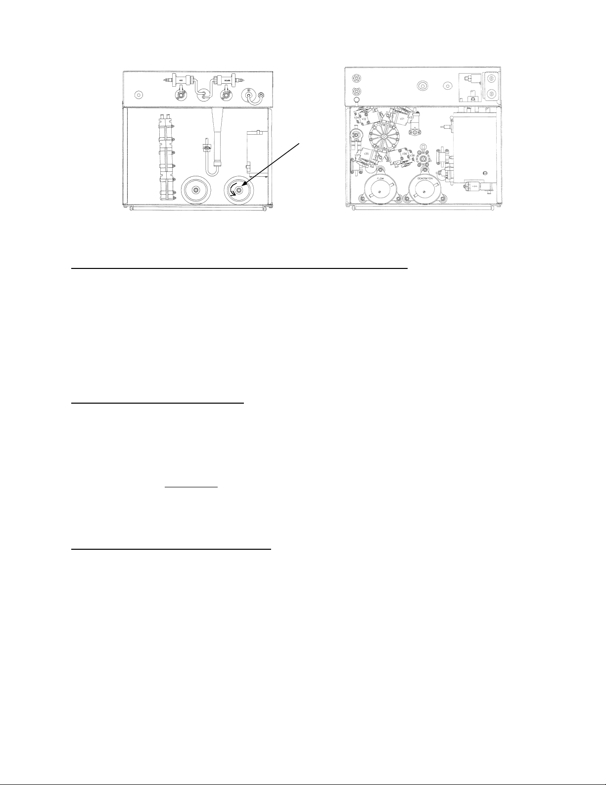
CLEAN- 2.0.1 CHECK VALVE #29
a) Interrupt the RINSE program by pulling the ACID connector from its port.
b) Clamp the clear tubing at the input nozzle of valve 29, as close to the valve as possible (see Figure 18
belo
w), and remove the tubing from the valve.
c) Fill a syringe with water with tubing attached the same size as the input nozzle of valve 29. Attach the
tubing to the input nozzle of valve 29.
d) Place the ACID connector back into its port and place the machine into RINSE.
e) Call debug screen 0, when V29 is energized (circle solid blue) try to push water through the valve. Are you
able to push water through the valve?
Yes See CLEAN- 2.0.2
A problem is indicated with the actuator board or VALVE #29. NOTE this and see
No
TROUBLESHOOTING VALVES (page 30).
VALVE 43 OUTPUT NOZZLE VALVE 29 INPUT NOZZLE
Figure 18 – Hydraulics (Top View)
Page 28
Fresenius 2008K Troubleshooting Guide
P/N 507298 Rev. C
Page 37

Section 3 – Flow Errors in Cleaning Programs
CLEAN- 2.0.2 CHECK VALVE #43
a) Connect the tubing back to valve #29 and REMOVE the clamp.
b) Clamp and remove the output tubing from valve #43 (see Figure 18, on previous page).
c)
From debug screen 0, when V43 is energized (circle solid blue) is there good ‘pulsing’ flow from the nozzle?
Yes See CLEAN- 2.0.3
A problem is indicated with the actuator board or VALVE #43. NOTE this and see
No
TROUBLESHOOTING VALVES (page 30).
CLEAN- 2.0.3 CHECK ACTUATOR BOARD SIGNAL
a) Place the machine into DIALYSIS PROGRAM and unplug valve #30 from its distribution board position
(V30, DRAIN-V). Using a flashlight check inside the distribution board for ‘white’ corrosion (indicative of
spillage).
b) If no corrosion: set your voltage meter to DC volts. Clip the leads BETWEEN male
pins 1 and 5 (top and
bottom) inside the distribution board. Place the red lead on pin 5 (bottom). Less than 2 volts?
Yes Replace valve #30.
No Replace the actuator board.
CLEAN- 3.0.0 CHECK FLOW ERROR
Place the machine into whatever cleaning program the flow error was occurring. If the flow error is still
present. Possibilities:
Bad deaeration motor brushes (especially if they have not been replaced in the last 8000 hours).
Bad deaeration pump head.
Bad (intermittent) dialysate pressure transducer #9.
Fresenius 2008K Troubleshooting Guide
P/N 507298 Rev. C
Page 29
Page 38

Section 3 – Flow Errors in Cleaning Programs
TROUBLESHOOTING VALVES
The troubleshooting procedure that brought you here asked you to NOTE which valve is the problem.
Proceed ONLY with the NOTED valve!
a) Unplug the NOTED valve from its distribution board position as instructed in Table 2 below. Using a
flashlig
b) If no corrosion: inside the distribution board there should be five male pins. Check for bent or broken
male pins.
c) If all pins are okay: set your voltage meter to DC volts. Clip the leads, inside the distribution board,
BETWEEN male
d) Some valves are checked from RINSE program, others in DIALYSIS program as instructed in the table
below. Place the machine into the indicated program.
e) Call debug screen 0. The valve is ‘energized’ when the circle (next to the valve) is solid blue. In RINSE
program some valves are ‘energized’ only at certain times. Take the voltage measurement ONLY when
the valve is energized.
Table 2 – Troubleshooting Valves
ht check inside the distribution board for ‘white’ corrosion (indicative of spillage).
pins 1 and 5 (top and bottom). Clip the red lead on pin 5 (bottom).
VALVE
DISTRIBUTION
POSITION
PROGRAM
MODE
GOOD
(22 to 26 Volts DC)
24 V24, DIAL-V1 RINSE Valve #24 bad or restricted
26 V26, BYPASS-V RINSE Valve #26 bad or restricted
29 V29, REC-V RINSE
43 V43 RINSE
Valve #29 bad or restricted
Valve #43 bad or restricted
25 V25, DIAL-V2 RINSE Valve #25 bad or restricted
39 V39, DEAR-V RINSE Valve #39 bad or restricted
41 V27 DIALYSIS Valve #41 bad or restricted
30 V30, DRAIN-V DIALYSIS
Valve #30 bad or restricted
BAD
(0 to 22 Volts DC)
Two possibilities:
1
1)
Bad actuator cable
2) Bad actuator board
Two possibilities:
1
Bad actuator cable
1)
2) Bad actuator board
Two possibilities:
1
Bad actuator cable
1)
2) Bad actuator board
Two possibilities:
1
1)
Bad actuator cable
2) Bad actuator board
Two possibilities:
1
1)
Bad actuator cable
2) Bad actuator board
Two possibilities:
1
1)
Bad actuator cable
2) Bad actuator board
Two possibilities:
1
1)
Bad actuator cable
2) Bad actuator board
Two possibilities:
1
Bad actuator cable
1)
2) Bad actuator board
1
The actuator cable can be checked for continuity. Note that you are checking DEAERATION PUMP
connections and see SECTION 16 - CHECKING ACTUATOR BOARD
CABLE (page 88).
Page 30
Fresenius 2008K Troubleshooting Guide
P/N 507298 Rev. C
Page 39

Section 3 – Flow Errors in Cleaning Programs
TROUBLESHOOTING VALVE ERRORS
Valve errors indicate a resistance problem in a ‘valve circuit’ and are generated when the actuator board tries
to ‘energize’ that valve’s solenoid. The easiest (and best) place to check is at the actuator board.
a) IMPORTANT! Turn the power off and slide electronic card cage forward.
b) Clip a ground lead onto PGND-B at the motherboard’s TEST connector (see Figure 19 below). If the
–12 volt conv
–12 volts converter correctly before placing the machine back into service.
erter board is plugged in here remove it for now. IMPORTANT! Make sure to reinstall the
P2 CONNECTOR
PIN 2 (TOP)
TEST CONNECTOR
(FOR GROUND)
ACTUATOR BOARD
(SOLDER SIDE)
PIN 1 (BOTTOM)
REAR OF MACHINE
Figure 19 – Electronic Card Cage
c) At the top of the actuator board (second board from the left) there is a 50-pin connector called 'P2' (see
Figure 19 above). The actuator ribbon-cable terminates here. Assure the
d) The actuator cable runs into the distribution board and terminates at the ACTUATOR connector. Assure
the cable is plugged in properly at the distribution board.
e) Check the actuator ribbon-cable for damage along its entire length. Replace if damaged.
f) From the solder (back) side of the actuator board’s ‘P2’ connector note that there are two rows of pins. All
‘odd’ numbered pins (1, 3, 5, etc) are in the bottom row. The ‘even’ numbered pins (2, 4, 6, etc) are in the
top row. Each ‘valve circuit’ will be checked by measuring resistance from these pins. It will be easier to
use a meter ‘probe’ instead of a clip-on lead!
g) The troubleshooting procedure that brought you here asked you to note which machine program the valve
error is occurring. Is the VALVE ERROR occurring in RINSE or DIALYSIS program?
DIALYSIS See VE- 1.0.0
cable is plugged in properly.
RINSE
VE- 1.0.0 VALVE ERRORS OCCURING IN DIALYSIS
See VE- 2.0.0
CAUTION! If VERR reaches 255 (its maximum) the valve error cannot be determined. If VERR reaches 255
turn the power off, back on, return to DIALYSIS program and continue from where you left off.
a) Turn the power on and place the machine into DIALYSIS program.
b) Call debug screen 1. If VERR is not increasing do NOT continue!
c) Allow 20 seconds and call screen 0. Is a NO WATER ALARM indicated?
Yes See VE- 1.0.1
See VE- 1.0.2
No
Fresenius 2008K Troubleshooting Guide
Page 31
P/N 507298 Rev. C
Page 40

Section 3 – Flow Errors in Cleaning Programs
VE- 1.0.1 VALVE ERROR AT VALVE #41
A NO WATER alarm is indicated.
a) IMPORTANT! Turn the power off.
b) Set your meter to resistance (Ω) and measure from the solder (back) side pin, of the actuator board ‘P2’
connector, as directed in Table 3 below. IMPOR
TANT! A reading like 2.42 MΩ is 2.42 million Ohms.
Table 3 – Troubleshooting Valve Error at Valve #41
VALVE PIN
41 32
VE- 1.0.2 VE- 1.0.1 CHECK FOR A VALVE ERROR AT VALVE #25
a) Call debug screen 1.
b) Open the shunt door (to closes valve #25). Does VERR stop increasing (and not = 255)?
Yes See VE- 1.0.3
No
See VE- 1.0.4
P2 PIN
LOCATION
Top row, 10 pins
from front
GOOD = BETWEEN
40 Ω AND 100 Ω
Replace the
actuator board
BAD = LESS THAN 40 Ω OR
GREATER THAN 100 Ω
Greater than 100 Ω, See VE- 3.0.0
Less than 4
0 Ω, See VE- 4.0.0
VE- 1.0.3 VALVE ERROR AT VALVE #25
VERR stopped increasing when you opened the shunt door.
a) IMPORTANT! Turn the power off.
b) Set your meter to resistance (Ω) and measure from the solder (back) side pin, of the actuator board ‘P2’
connector, as directed in the table below. IMPORTANT! A reading like 2.42 MΩ is 2.42 million ohms!
Table 4 - Troubleshooting Valve Error at Valve #25
VALVE PIN
25 30
VE- 1.0.4 VE- 1.0.2 CHECK FOR A VALVE ERROR AT A BALANCING CHAMBER VALVE
Turn dialysate flow off (flow on/off LED on). This closes all eight balancing chamber valves. Does VERR stop
increasing (and not = 255)?
Yes See VE- 1.0.5
No
See VE- 1.0.6
P2 PIN
LOCATION
Top row, 11 pins
from front
GOOD = BETWEEN
40 Ω AND 100 Ω
Replace the
actuator board
BAD = LESS THAN 40 Ω OR
GREATER THAN 100 Ω
Greater than 100 Ω, See VE- 3.0.0
Less than 4
0 Ω, See VE- 4.0.0
Page 32
Fresenius 2008K Troubleshooting Guide
P/N 507298 Rev. C
Page 41

Section 3 – Flow Errors in Cleaning Programs
VE- 1.0.5 VALVE ERROR AT BA
LANCING CHAMBER VALVES
VERR stopped increasing when you turned dialysate flow off.
a) IMPORTANT! Turn the power off.
b) Set your meter to resistance (Ω) and measure from the solder (back) side pins, of the actuator board ‘P2’
connector, as directed in the table below. IMPORTANT! A reading like 2.42 MΩ is 2.42 million ohms!
Table 5 - Troubleshooting Valve Error at Balancing Chamber Valves
VALVE PIN
31 36
32 37
33 38
34 39
P2 PIN
LOCATION
Top row, 8 pins
from front
Bottom row, 7
pins from front
Top row, 7 pins
from front
Bottom row, 6
pins from front
GOOD = BETWEEN
40 Ω AND 100 Ω
Check also valve #32
Check also valve #33
Check also valve #34
Check also valve #35
BAD = LESS THAN 40 Ω OR
GREATER THAN 100 Ω
Greater than 100 Ω, See VE- 3.0.0
Less than 4
0 Ω, See VE- 4.0.0
Greater than 100 Ω, See VE- 3.0.0
Less than 4
0 Ω, See VE- 4.0.0
Greater than 100 Ω, See VE- 3.0.0
Less than 4
0 Ω, See VE- 4.0.0
Greater than 100 Ω, See VE- 3.0.0
Less than 4
0 Ω, See VE- 4.0.0
35 40
36 41
37 42
38 43
Top row, 6 pins
from front
Bottom row, 5
pins from front
Top row, 5 pins
from front
Bottom row, 4
pins from front
Check also valve #36
Check also valve #37
Check also valve #38
Replace the actuator
board
Greater than 100 Ω, See VE- 3.0.0
Less than 4
0 Ω, See VE- 4.0.0
Greater than 100 Ω, See VE- 3.0.0
Less than 4
0 Ω, See VE- 4.0.0
Greater than 100 Ω, See VE- 3.0.0
Less than 4
0 Ω, See VE- 4.0.0
Greater than 100 Ω, See VE- 3.0.0
Less than 4
0 Ω, See VE- 4.0.0
Fresenius 2008K Troubleshooting Guide
P/N 507298 Rev. C
Page 33
Page 42

Section 3 – Flow Errors in Cleaning Programs
VE- 1.0.6 VALVE ERROR AT VALVE #30 OR VALVE #26
VERR continued to increase with the shunt door open and with dialysate flow off.
a) IMPORTANT! Turn the power off.
b) Set your meter to resistance (Ω) and measure from the solder (back) side pins, of the actuator board ‘P2’
connector, as directed in the table below. IMPORTANT! A reading like 2.42 MΩ is 2.42 million ohms!
Table 6 - Troubleshooting Valve Error at Valve #30 or Valve #26
VALVE PIN
30 35
26 31
VE- 2.0.0 VALVE ERRORS OCCURRING IN RINSE
The troubleshooting procedures in SECTION 3 - FLOW ERRORS IN CLEANING PROGRAMS asked you to
note where valve error is occurring. Proceed ONLY with that valve.
a) IMPORTANT! Turn the power off.
b) Set your meter to resistance (Ω) and measure from the solder (back) side pin, of the actuator board ‘P2’
connector, as directed in the table below. IMPORTANT! A reading like 2.42 MΩ is 2.42 million ohms!
P2 PIN
LOCATION
Bottom row, 8
pins from front
Bottom row, 10
pins from front
GOOD = BETWEEN
40 Ω AND 100 Ω
Check also valve #26
Replace the actuator
board
BAD = LESS THAN 40 Ω OR
GREATER THAN 100 Ω
Greater than 100 Ω, See VE- 3.0.0
Less than 4
Greater than 100 Ω, See VE- 3.0.0
Less than 4
0 Ω, See VE- 4.0.0
0 Ω, See VE- 4.0.0
Table 7 - Troubleshooting Valve Errors Occurring in Rinse
VALVE PIN
39 44
29 34
43 46
P2 PIN
LOCATION
Top row, 4 pins
from front
Top row, 9 pins
from front
Top row, 3 pins
from front
GOOD = BETWEEN
40 Ω AND 100 Ω
Replace the actuator
board
Replace the actuator
board
Replace the actuator
board
BAD = LESS THAN 40 Ω OR
GREATER THAN 100 Ω
Greater than 100 Ω, See VE- 3.0.0
Less than 4
Greater than 100 Ω, See VE- 3.0.0
Less than 4
Greater than 100 Ω, See VE- 3.0.0
Less than 4
0 Ω, See VE- 4.0.0
0 Ω, See VE- 4.0.0
0 Ω, See VE- 4.0.0
Page 34
Fresenius 2008K Troubleshooting Guide
P/N 507298 Rev. C
Page 43

Section 3 – Flow Errors in Cleaning Programs
VE- 3.0.0 CHECK FOR AN 'OPEN' (GREATER THAN 100 Ω )
VALVE CIRCUIT
a) Verify that the NOTED valve is plugged into the correct location on the distribution board (for example,
valve 36 plugs into position V36). Note that valve 41 plugs into the position labeled 27IN-V.
b) Unplug the NOTED valve from its distribution board position. Using a flashlight, check inside the
distribution board, for ‘white’ corrosion (indicative of spillage).
c) If no corrosion: inside the distribution board there should be five male pins. Check for bent or broken
male pins.
d) If all pins are okay: open the female connector’s, plastic, cover and check for good solder connections.
e) Leaving the connector unplugged measure resistance, inside the female
connector, between pins 1 and 5
(where the wires are soldered). Note that valve 26 is wired to pins 2 and 5. Is the resistance between 40
and 100 Ω?
Yes See VE- 3.0.1
See VE- 3.0.2
No
VE- 3.0.1 CHECK ACTUATOR BOARD CABLE
a) Unplug the 50-conductor actuator cable from both ends (the cable terminates at actuator board and at the
distribution board’s ACTUATOR connector).
b) Using a flashlight, check the male side of both connectors for ‘white’ corrosion (indicative of spillage).
c) If no corrosion: check for bent or broken male pins.
d) If all pins are okay: replace the actuator cable.
Fresenius 2008K Troubleshooting Guide
P/N 507298 Rev. C
Page 35
Page 44

Section 3 – Flow Errors in Cleaning Programs
VE- 3.0.2 CHECK VALVE SOLENOID
Each valve has a two-wire harness that runs from the distribution board and terminates at its solenoid where it
plugs onto two male terminals (see Figure 20 and Figure 21 below to locate the valve). Unplug the two-wire
harn
ess and measure between the male
solenoid terminals. Between 40 and 100 Ω?
Yes The two-wire harness is bad.
No Replace the valve.
VALVE 34
(BEHIND VALVE 32)
VALVE 32
VALVE 37
(BEHIND VALVE 35)
VALVE 35
VALVE 33
(BEHIND VALVE 31)
VALVE 31
VALVE 38
(BEHIND VALVE 36)
VALVE 36
VALVE 39
Figure 20 – Hydraulics (Rear View)
VALVE 26
VALVE 24
VALVE 43 VALVE 29 VALVE 41
VALVE 30
Figure 21 – Hydraulics (Top View)
Page 36
Fresenius 2008K Troubleshooting Guide
P/N 507298 Rev. C
Page 45

Section 3 – Flow Errors in Cleaning Programs
VE- 4.0.0 CHECK FOR A ‘SHORTED’ (LESS THAN 40 Ω )VA
LVE CIRCUIT
IMPORTANT! A previous reading like 2.42 MΩ is 2.42 million ohms! A reading like 2.42 KΩ is 2.42 thousand
ohms. Make CERTAIN that you are reading the meter correctly before continuing with these procedures!
a) Assure that the NOTED valve is plugged into the distribution board at the correct location (for example,
valve 36 plugs into position V36).
b) Unplug the NOTED valve from its distribution board position. Using a flashlight check, inside the
distribution board, for ‘white’ corrosion (indicative of spillage).
c) If no corrosion: do NOT plug the valve into the distribution board yet. Measure resistance again at the
NOTED valve's actuator board ‘P2’ connector pin (as instructed in the table). Greater than 2 MΩ (possibly
O.L., depends on meter)?
Yes Replace the valve (shorted solenoid). See Figure 20 and Figure 21 (on previous page), to
locate the val
ve.
No See VE- 4.0.1
VE- 4.0.1 CHECK ACTUATOR BOARD FOR A ‘SHORT’
Unplug the 50-conductor actuator ribbon-cable from the actuator board and measure resistance again at the
NOTED valve's actuator board ‘P2’ connector pin (as instructed in the table). Greater than 2 MΩ (possibly
O.L., depends on meter)?
Yes Using a flashlight check, inside the actuator board male connector, for bent or broken pins. If
okay: replace the actuator board (shorted valve driver).
No See VE- 4.0.2
VE- 4.0.2 CHECK ACTUATOR BOARD CABLE CONNECTIONS
a) Using a flashlight check, inside the actuator board male connector, for bent or broken pins. If okay, plug
the actuator cable back into the actuator board.
b) Unplug the 50-conductor actuator ribbon-cable from the distribution board’s ACTUATORS connector.
Using a flashlight check, inside the distribution board’s ACTUATOR connector, for ‘white’ corrosion
(indicative of spillage).
c) If no corrosion: check, inside the distribution board’s ACTUATOR connector, for bent or broken male pins.
d) If all pins are okay: measure resistance again at the NOTED valve's actuator board ‘P2’ connector pin (as
instructed in the table). Greater than 2 MΩ (possibly O.L., depends on meter)?
Yes See VE- 4.0.3
Replace the actuator ribbon-cable.
No
Fresenius 2008K Troubleshooting Guide
P/N 507298 Rev. C
Page 37
Page 46

Section 3 – Flow Errors in Cleaning Programs
VE- 4.0.3 CHECK ACTUATOR CONNECTOR PINS/ VALVE HARNESS
a) Check the 2-pin wiring harness that runs from the NOTED valve's distribution board connector to the valve,
for exposed wire.
b) Plug the actuator cable back the distribution board’s ACTUATORS connector.
c) Plug the valve back into the distribution board. IMPORTANT! Be SURE to plug the valve into the correct
position!
d) Measure resistance again at the NOTED valve's actuator board ‘P2’ connector pin (as instructed in the
table). Between 40 and 100Ω?
Yes There may have been a bad connection at the distribution board.
No VE- 4.0.4
VE- 4.0.4 CHECK VALVE SOLENOID
a) Locate the noted valve (use Figure 20 and Figure 21 on page 36).
b)
Unplug the two-wire distribution board harness directly from the solenoid.
c) Measure resistance BETWEEN the solenoid terminals. ). Between 40 and 100Ω?
Yes Possible: 1) Bad actuator cable; 2) Bad two-wire valve harness; 3)Bad actuator board; 4) Bad
distribution board
No Replace the valve.
Page 38
Fresenius 2008K Troubleshooting Guide
P/N 507298 Rev. C
Page 47

SECTION 4 - TEMPERATURE PROBLEMS
Read the following list of symptoms and proceed with the one that best describes the problem:
1. Machine is in DIALYSIS program and:
o
Temperature remains less than 30
Temperature increases to about 40
2. You are attempting HEATER CONTROL CALIBRATION and:
Temperature stabilizes but will not calibrate to 37
see T- 1.0.0.
Temperature increases to about 40
and see T- 4.0.0.
Machine is HEAT DISINFECT program and:
3.
Temperature remains less than 30
Temperature fails to reach 80
Temperature increases to about 90
C. See T- 1.0.0.
o
C falls and rises again. See T- 4.0.0.
o
C. Return to DIALYSIS program and
o
C falls and rises again. Return to DIALYSIS program
o
C. Return to DIALYSIS program and see T- 1.0.0.
o
C but is greater than 30ºC. See T- 3.0.0.
o
C falls and then rises again. See T- 4.0.0.
T- 1.0.0 CHECK HEATER BREAKER AND NO WATER AND FLOW ERROR
a) Make sure the heater breaker switch (rear panel) is on. If not this is the problem!
b) Call debug screen 0. Intermittent problems are easily missed with a ‘quick look’ so watch for two minutes
until you see either a NO WATER alarm or a flow error (FLOW ERROR = “1”). Proceed accordingly:
NO WATER alarm (intermittent or constant). See SECTION 2 - NO WATER (p
age 24).
FLOW ERROR = “0” (constant). See T- 1.0.1
FLOW ERROR = “1” (intermittent or constant). See SECTION 1- FLOW ERRORS IN DIALY
ZE
MODE (page 6).
T- 1.0.1 CHECK TEMPERATURE SET POINT
a) Push the blue HOME screen button to return to the main screen
b) Push the yellow Temperature data button (it turns a dark yellow). Now displayed is the current Temp.
Setting. Is temperature set okay (per unit standards)?
Yes Push the CONFIRM key and see T-1.0.2
No
Use the UP or DOWN arrow keys to adjust and push the CONFIRM key. Allow 10 minutes
for stabilization.
or
Fresenius 2008K Troubleshooting Guide
P/N 507298 Rev. C
Page 39
Page 48

Section 4 – Temperature Problems
T- 1.0.2 CHECK HEATER VOLTAGE
CAUTION 120 VOLTS! Carefully measure ac (~) voltage, BETWEEN the BLUE and BROWN heater wires at
the distribution board's heater connector (see Figure 22 below). Voltage may be 'pulsing' causing the meter
to overload
(O.L.) intermittently (this is normal). Greater than 90 volts?
Yes See T- 1.0.3
No See T- 2.0.0
HEATER CONNECTOR
NTC-2 NTC-3
BLUE WIRE BROWN WIRE
Figure 22 – Distribution Board
T- 1.0.3 CHECK HEATER
IMPORTANT turn the POWER OFF!
Measure RESISTANCE () between the BLUE and BROWN heater
wires (see Figure 22 above). Between 9 and 13 Ω?
Yes See T- 5.0.0 (page 51).
Replace the heater.
No
Page 40
Fresenius 2008K Troubleshooting Guide
P/N 507298 Rev. C
Page 49

Section 4 – Temperature Problems
T- 2.0.0 CHECK LOGIC SIGNALS
CAUTION! During these procedures, DC voltages are measured at the solder (back) side of the POWER
LOGIC BOARD'S ‘x2’ connector. The pins are very close to each other
and 'shorting' them together with a
meter probe can damage the board. It is recommended that you use Fluke TP80 meter probes together with
the slip-on cap
(see Figure 5 on page 4).
a) Turn the power off and clip a ground lead onto SGND at the TEST connector (see Figure 23 below).
At the top, very front of the POWER LOGIC BOARD (first board from the left) is the 20-pin 'x2' connector
b)
(see Figure 23 below). A ribbon cable terminates here that runs into the power supply. The solder (rear)
ns are in two rows. In the top row are even numbered (2, 4, etc) pins, in the bottom row are odd (1,
side pi
3, etc) numbered pins.
c) Turn power on and place the machine into DIALYSIS PROGRAM. Wait 20 seconds and measure DC
voltage at the pins specified in the Table 8 below. Follow the directions given in Table 8.
POWER LOGIC
BOARD
TEST CONNECTOR
(FOR GROUND)
PIN 6
PIN 2
PIN 7
POWER LOGIC BOARD
(SOLDER SIDE)
x2 CONNECTOR
REAR OF
MACHINE
x2 CONNECTOR
Figure 23 – Electronic Card Cage
Table 8 – Logic Signals
PIN x2 LOCATION GOOD SIGNAL (volts dc) BAD SIGNAL (volts dc)
top row, three pins from
6
the rear
bottom row, four pins
7
from the rear
top row, first pin from
2
the rear
9.6 or greater, measure at
x2, pin 7
4 or greater, measure at x2,
pin 2
3.6 or lower, see T- 2.1.0
3 or lower, see T- 2.2.0
2 or lower, see T- 2.4.0 9 or higher, see T- 2.3.0
Fresenius 2008K Troubleshooting Guide
P/N 507298 Rev. C
Page 41
Page 50

Section 4 – Temperature Problems
T- 2.1.0 CHECK SENSOR BOARD SIGNAL
a) At the very BOTTOM of the SENSOR board (first board on the right) is its motherboard connector (see
Figure 24 below). A row of pins extend
s horizontally from the board, turn 90 degrees downward and runs
into the motherboard connector. This is the "C row", numbered 1 through 32 (from front-to-rear).
SENSOR BOARD
FRONT OF
MACHINE
MOTHER BOARD
CONNECTOR
PIN C1
Figure 24 – Electronic Card Cage
b) Do NOT use the slip on cap: measure DC voltage at pin C1 (very FRONT motherboard pin). High (9.6 volts
or greater) or low (less than 3.6 volts)?
High See T- 2.1.2
Low See T- 2.1.1
T- 2.1.1 CHECK POWER LOGIC BOARD
a) Turn the power off and swap in a known good power logic board.
b) Turn the power on and measure at the power logic board's x2 connector, pin 6. High (9.6 volts or greater)
or low (3.6 volts or lower)?
High Problem solved (the previous power logic board is bad)
Low See T- 2.5.0 (the previou
T- 2.1.2 CHECK NTC-2
s power logic board is good)
Unplug NTC-2 from the distribution board (first position on left, x2 CON-NTC) and measure again at pin C1.
High (9.6 volts or greater) or low (less than 3.6 volts)?
Low Replace NTC-2.
High See T- 2.1.3.
Page 42
Fresenius 2008K Troubleshooting Guide
P/N 507298 Rev. C
Page 51

Section 4 – Temperature Problems
T- 2.1.3 CHECK NTC-2 CIRCUIT
a) Turn the power off and unplug both ends of the 34-conductor sensor board cable. Using a flashlight, check
for bent, broken or corroded male
pins at each connector.
b) If no corrosion: plug both ends of the cable back in and swap in a known good power logic board.
c) Turn the power back on and measure again at the sensor board's motherboard pin C1. High (9.6 volts or
greater) or low (3.6 volts or lower)?
High Replace the sensor board (the previous power logic board is good).
Low Problem solved (the previous power logic board is bad).
T- 2.2.0 CHECK FOR FLOW ERRORS
Call debug screen 0. Is FLOW ERROR = "1"?
Yes See SECTION 1- FLOW ERRORS IN
DIALYSIS PROGRAM (page 6).
No See T- 2.2.1
T- 2.2.1 CHECK ACTUATOR BOARD
a) Turn the power off and swap in a known good actuator board.
b) Turn the power on and place the machine into DIALYSIS PROGRAM.
c) Measure again at the power logic board's ‘x2’ connector, pin 7 (bottom row, 4 pins from rear). High (greater
than 4 volts) or low (less than 1.5 volts)?
High The previous actuator board is bad.
Low See T- 2.5.0 (the previou
T- 2.3.0 CHECK POWER LOGIC/FUNCTION BOARD
s actuator board is good).
a) Turn the power off and swap in a known good power logic board.
b) Turn the power on and place the machine into DIALYSIS PROGRAM.
c) Wait 15 seconds
and measure again at the solder side of the power logic board's ‘x2’ connector, pin 2 (top
row, first pin from rear). Less than 2 volts now?
Yes The previous power logic board was bad.
No Replace the function board (the previous power logic board is good).
Fresenius 2008K Troubleshooting Guide
P/N 507298 Rev. C
Page 43
Page 52

Section 4 – Temperature Problems
T- 2.4.0 CHECK HEATER RELAY
a) Turn the power off and then back on. Allow the SELECT PROGRAM screen to come up.
IMPORTANT! Do NOT
enter dialysis program.
b) From SELECT PROGRAM measure again at the solder side of the power logic board's x2 connector, pin 2
(top row, first pin from rear). Between 22 and 26 volts?
Yes See T- 2.6.0.
No
T- 2.5.0 CHECK POWER LOGIC CABLE/POWER CONTROL BOARD
See T- 2.5.0
Either the 20-pin power logic board cable or the power control board is bad.
a) Turn the power off and UNPLUG the machine. CAUTION, 120 VOLTS IF NOT UNPLUGGED!
b) Slide the power supply (see Figure 6, page 5) away from the cabinet. Inside is the power control board
re the 20-pin 'x2' cable terminates. Check that the cable is plugged in properly.
whe
c) Un-mount the power control board from the plastic clips to allow easy access to the rear (solder) side
(see Figure 25 below).
Measure resistance from pin 2, at the POWER LOGIC BOARD'S
d)
first pin from rear), to pin 2 at the POWER CONTROL BOARD'S
end of the cable (x2 connector, top row,
end. If the cable is good (10 Ω or less),
replace the POWER CONTROL BOARD.
PIN 2 PIN 7
x2 CONNECTOR
PIN 6
K1
K2
ST 9
ST 8 ST 11
ST 13
ST 5
ST 4
ST 7
Figure 25 – Power Control Board (Solder Side)
Page 44
Fresenius 2008K Troubleshooting Guide
P/N 507298 Rev. C
Page 53

Section 4 – Temperature Problems
T- 2.6.0 CHECK POWER LOGIC BOARD CABLE
a) Turn the power off and UNPLUG the machine. CAUTION, 120 VOLTS IF NOT UNPLUGGED!
b) Slide the upper power supply (see Figure 6, page 5) away from the cabinet. Inside is the power control
board wh
ere the 20-pin 'x2' cable terminates. Check that the cable is plugged in properly.
c) Un-mount the power control board from the plastic clips to allow easy access to the rear (solder) side
(see Figure 25 on previous page). Measure resistance () from:
Pin 6, at the POWER LOGIC BOARD'S
1)
rear), to pin 6 at the POWER CONTROL BOARD'S
2) Pin 7, at the POWER LOGIC BOARD'S
from rear), to pin 7 at the POWER CONTROL BOARD'S
end of the cable (‘x2’ connector, top row, three pins from
end (see Figure 25 on previous page).
end of the cable (‘x2’ connector, bottom row, four pins
end (see Figure 25 on previous page).
d) If both measurements are good (10 Ω or less) see T- 2.6.1.
T- 2.6.1 CHECK TRIAC VOLTAGE DROP
a) Set meter to ac (~) volts and CLIP the leads, onto the SOLDER (rear) side of the power control board,
BETWEEN connectors ST8 and ST11 (see Figure 25 on previous page).
b)
Plug the machine in. CAUTION, 120 VOLTS NOW PRESENT!
c) Turn the power on and place the machine into DIALYSIS PROGRAM. Wait 15 seconds
. Greater than
90 volts across the triac?
Yes See T- 2.6.2
See T- 2.7.0
No
T- 2.6.2 CHECK TRIAC GATE SIGNAL
a) Turn the power off and UNPLUG the machine. CAUTION, 120 VOLTS IF NOT UNPLUGGED!
b) CLIP meter leads BETWEEN connectors K2 and ST9 on the SOLDER (rear) side of the power control
board (see Figure 25 on previous page).
Plug the machine in. CAUTION, 120 VOLTS NOW PRESENT!
c)
d) Turn the power on and place the machine into DIALYSIS PROGRAM. Wait 15 seconds
. 90 volts or
greater?
Yes Bad power control board.
No Bad triac (trace the orange wire from connector ST9 to the triac).
T- 2.7.0 CHECK HEATER CONNECTIONS
a) Turn the power off and UNPLUG the machine. CAUTION, 120 VOLTS IF NOT UNPLUGGED!
b) Measure resistance (Ω), on the SOLDER (rear) side of the power control board, BETWEEN connectors
K2 and K1 (see Figure 25 on previous page). Less than 20 Ω?
Yes See T- 2.7.1
No
Check for an open circuit between the power supply and the heater.
Fresenius 2008K Troubleshooting Guide
P/N 507298 Rev. C
Page 45
Page 54

Section 4 – Temperature Problems
T- 2.7.1 CHECK HEATER BREAKER
Referring to Figure 25 on the page 44 measure resistance on the SOLDER (rear) side of the power control
board, BETWEEN con
nectors:
ST 7 and ST 13;
ST 4 and ST 5.
Both measurements less than 30 Ω?
Yes See T- 2.7.2
Bad heater breaker ('open')
No
T- 2.7.2 CHECK HEATER VOLTAGE
a) Turn the power on and place the machine into DIALYSIS PROGRAM.
b) CAUTION 120 VOLTS! Measure ac (~) voltage, between the GREEN and BROWN heater wires at the
distribution board's heater connector (see Figure 26 below). Greater than 90 volts?
Yes
All systems are checking good.
No Replace the power control board (inside power supply).
HEATER CONNECTOR
NTC-2 NTC-3
GREEN WIRE
Figure 26 – Distribution Board
T- 3.0.0 CHECK TEMPERATURE DISPLAY
From HEAT DISINFECT, plug the 80
distribution board. Does the Temperature display (on the screen) read between 77
Yes See T- 3.0.1
No
See T- 6.0.0 (page 52)
Page 46
o
C Fresenius temperature 'dummy' connector into NTC-3 on the
Fresenius 2008K Troubleshooting Guide
P/N 507298 Rev. C
BLUE WIRE
o
C and 85oC ?
BROWN WIRE
Page 55

Section 4 – Temperature Problems
T- 3.0.1 CHECK RECIRCULATION
a) Go to end of the drain tubing. Hold the tubing so that the opening is pointed UPWARD!
(at about 45
degrees). CAUTION!! If the opening is held DOWNWARD this test is invalid.
b) Call debug screen 0. When V29 is energized the circle, next to the valve, turns solid blue. Wait until V29 is
energized CONSTANTLY. Is there flow to the drain?
Yes See T- 3.0.2
See T- 3.0.3
No
T- 3.0.2 CHECK VALVE #30
Unplug valve #30 from the distribution position V30. Using a flashlight check, inside the distribution board for
corrosion (indicative of spillage). If no corrosion: does flow to the drain stop?
Yes Replace the actuator board (shorted driver).
No Replace valve #30 (leaking).
T
- 3.0.3 CHECK HEATER
a) Turn the heater breaker switch (rear panel) off and wait 15 minutes
b) Turn the POWER OFF
and measure RESISTANCE (), between the BROWN and BLUE heater wires at
.
the distribution board's heater connector (see Figure 26 on previous page). Between 9 and 13 Ω?
Note that NTC-2 OR NTC-3 may be a problem and see T- 9.0.0 (p
Yes
age 53).
No Replace the heater
Fresenius 2008K Troubleshooting Guide
P/N 507298 Rev. C
Page 47
Page 56

Section 4 – Temperature Problems
T- 4.0.0 CHECK SENSOR BOARD SIGNAL
a) Turn the power off and clip a ground lead onto SGND at the TEST connector (see Figure 27 below).
NOTE: Tro
to DIALYSIS PROGRAM
ubleshooting this symptom CANNOT be done in HEAT DISINFECT. If in HEAT DISINFECT return
.
o
b) Plug the 80
C Fresenius temperature 'dummy' connector into NTC-2's distribution board position (FIRST!
position on the left, CON-NTC). CAUTION! Be careful to plug in correctly!
c) At the very BOTTOM of the SENSOR board (first board from the right) is its motherboard connector (see
Figure 27 below). A row of pins extend
s horizontally from the board, turn 90 degrees downward and runs
into the motherboard connector. This is the "C row", numbered 1 through 32 (from front-to-rear).
d) Turn the power on. Do NOT use the TP80 slip-on cap: measure DC voltage at pin C1 (very FRONT
motherboard pin). High (9.6 vdc or greater) or low (less than 3.6 vdc)?
High Leave the 'dummy' in for now and see T- 4.1.0
Low Note
that NTC-2 may be a problem and see T- 9.0.0 (page 53).
SENSOR BOARD
FRONT OF
MACHINE
MOTHER BOARD
CONNECTOR
PIN C1
Figure 27 – Electronic Card Cage
Page 48
Fresenius 2008K Troubleshooting Guide
P/N 507298 Rev. C
Page 57

Section 4 – Temperature Problems
T- 4.1.0 CHECK LOGIC SIGNAL
CAUTION! During this procedure, DC voltages are measured at the solder (back) side of the POWER LOGIC
BOARD'S ‘x2’ connector. The pins are very close to each other and 'shorting' them together with a meter
probe can damage the board. It is recommended that you use Fluke TP80 meter probes together with the
slip-on cap (see Figure 5 on page 4).
At the top, very front of the POWER LOGIC BOARD (first board from the left) is the 20-pin 'x2' connector
a)
(see Figure 27 below). A ribbon cable terminates here that runs into the upper power supply. The solder
ar) side pins are in two rows. In the top row are even numbered (2, 4, 6, etc) pins, in the bottom row are
(re
odd (1, 3, 5, etc) numbered pins.
x2 CONNECTOR
REAR OF
MACHINE
POWER LOGIC
BOARD
TEST CONNECTOR
(FOR GROUND)
x2 CONNECTOR
PIN 6 PIN 2
POWER LOGIC BOARD
(SOLDER SIDE)
Figure 28 – Electronic Card Cage
b) Turn the power on and measure at the solder side of the x2 connector, pin 6 (top row, 3 pins from rear).
High (greater than 9.6 volts) or low (less than 3.6 volts)?
High See T- 4.2.0
Low
Watch the Temperature display (main screen) for 10 minutes. Does it drop to 33
o
Yes Replace NTC- 2
No Continues to increase, see T- 4.3.0
T- 4.2.0 CHECK POWER LOGIC BOARD
a) Turn the power off and swap the power logic board with a known good board.
b) Turn the power on and place the machine into DIALYSIS PROGRAM. Watch for 10 minutes. If
Temperature continues to increase to about 40
o
C replace the power control board (inside the power
supply).
C?
Fresenius 2008K Troubleshooting Guide
P/N 507298 Rev. C
Page 49
Page 58

Section 4 – Temperature Problems
T- 4.3.0 CHECK FOR A SHORTED TRIAC
a) Turn the power off and UNPLUG the machine. CAUTION, 120 VAC IF NOT UNPLUGGED!
b) Remove the power supply from the cabinet (see Figure 6, page 5). Inside the power supply is the power
control boa
rd, which is mounted to the case with plastic clips. Remove the board from the clips to allow
easier access to the back (solder) side of the board.
c) Measure RESISTANCE (), on the solder side of the power control board, between connectors ST8 and
ST11 (see SOLDER SIDE in Figure 29 below). Greater than 3 MΩ (or O.L.)
?
Yes See T- 4.4.0
No
Replace the triac.
ST 8 ST11 ST 9 (GATE)
SOLDER SIDE
COMPONENT SIDE
Figure 29 – Power Control Board
T- 4.4.0 CHECK TEMP CALIBRATION
a) Turn the power off and place the machine in SERVICE/CALIBRATION. Place a temperature meter into the
dialysate lines to measure 'actual' temperature. CAUTION Fluid may be hot!
b) Turn the power back on and enter HEAT TEMP CONTROL. Lower the DAC value to "0".
c) Watch 'actual' (on the meter) temperature for 10 minutes
Yes Leave the temperature meter in line for now and see T- 4.5.0
No
Plug NTC-2 back into the distribution board (first position from the left, CON-NTC) and
calibrate HEATER TEMP CONTROL.
. Continue to increase to high?
Page 50
Fresenius 2008K Troubleshooting Guide
P/N 507298 Rev. C
Page 59

Section 4 – Temperature Problems
T- 4.5.0 REMOVE TRIAC'S GATE SIGNAL
a) Turn the power off and UNPLUG the machine. CAUTION, 120 VOLTS IF NOT UNPLUGGED!
b) Unplug the female terminal connector from the power control board's (GATE) terminal ST 9 (see
COMPONENT SIDE in Figure 29 on previous page).
Wrap BLACK tape around the female
c)
terminal connector. CAUTION! The connector is 'live' (120 volts)
when the power is on. Damage to the machine or risk of shock if not wrapped.
d) Plug the machine in (CAUTION, 120 VOLTS NOW PRESENT!). Turn the power on and enter
CALIBRATION/HEATER TEMP CONTROL.
f) Lower the DAC value to "0" and watch 'actual' (on the meter) temperature for 10 minutes
increase to about 40
o
C?
. Continue to
Yes Replace the triac and calibrate HEATER TEMP CONTROL.
No Replace the power control board and calibrate HEATER TEMP CONTROL.
T- 5.0.0 CHECK TEMP DISPLAY
With the machine on in DIALYSIS PROGRAM, plug the 40
into NTC-3's position (second position from the left, MON-NTC). CAUTION! Plug in correctly. Does the
Temperature display (main screen) read between 38
Yes Note that NTC- 3 may be a problem and see T- 9.0.0 (pag
o
C Fresenius test (temperature) 'dummy connector'
o
C and 42oC?
e 53).
No See T- 6.0.0.
Fresenius 2008K Troubleshooting Guide
P/N 507298 Rev. C
Page 51
Page 60

Section 4 – Temperature Problems
T- 6.0.0 CHECK DEBUG TEMPERATURE VALUES
a) With the 40
o
C connector plugged call debug screen 4 and note:
TEMP (Good = 8.8 +/- 0.3 volts)
ATEM (Good = 7.7 +/- 0.3 volts)
b) Refer to the table below and follow the directions given.
Table 9 – Debug Temperature Values
DEBUG 4, TEMP DEBUG 4, ATEM RESPONSE
GOOD GOOD See T- 7.0.0
GOOD BAD Replace the actuator board
BAD GOOD Replace the sensor board
BAD BAD See T- 8.0.0
T- 7.0.0 CALIBRATE TEMPERATURE
a) Plug NTC-3 back into distribution board (SECOND! position from left, x3 MON-NTC). CAUTION! Be sure
to plug in correctly.
b) Calibrate HEATER TEMP CONTROL per CALIBRATION PROCEDURES. If not successful note that either
NTC- 2 or NTC- 3 may be a problem and see T- 9.0.0.
T- 8.0.0 CHECK TEST BOARD
a) Turn the machine off and swap in a known good test board. NOTE: An alternative is to remove IC 4 from
the test board. The machine runs okay without IC4 but will not pass tests.
o
b) Turn the power on and place the machine into DIALYSIS program. With the 40
C dummy connector
plugged in call debug screen 4. TEMP = 8.8 (+/- 0.3) volts?
Yes The previous test board (or IC 4, test board) is bad.
No Four possibilities: 1) *Bad sensor board cable; 2) HEATER TEMP CONTROL not calibrated
accurately; 3) Bad sensor board; 4) Bad function board.
*The sensor cable can be checked for continuity. Note that you are checking NTC-2 and NTC-3 connections
and see SECTION 17 - CHECKING SENSOR BOARD CABLE (p
age 90).
Page 52
Fresenius 2008K Troubleshooting Guide
P/N 507298 Rev. C
Page 61

Section 4 – Temperature Problems
T- 9.0.0 CHECK NTC RESISTANCE
Proceed ONLY with the NTC(s) as noted above.
a) Turn the POWER OFF
and remove the NTC(s) from their respective hydraulic location (see Figure 30
below).
DISTRIBUTION BOARD
NTC
PROBE END
NTC- 2
NTC- 3
CONNECTOR
Figure 30 – Hydraulics (Rear View)
b) Unplug the NTC from its distribution board connector (see Figure 31 below). Using a flashlight, check
insid
e the distribution board, for bent, broken, or corroded male
pins.
NTC-2 NTC-3
Figure 31 – Distribution Board
c) If no corrosion, remove the plastic cover from the NTC's female connector. Clip meter leads onto pins 1
and 3 (top and middle, typically green and white wires attached). Set the meter to RESISTANCE ().
o
d) Fill a Styrofoam cup with water between 36
C and 38oC. Water temperature should be ACCURATELY
measured with an external thermometer.
e) Drop the NTC 'probe' end into the water and allow 20 seconds for stabilization. Refer to Table 10 (next
).
page
Replace any NTC that checks bad and calibrate HEATER TEMP CONTROL.
If NTC(s) check good there are four possibilities: 1) *Bad sensor board cable; 2) HEATER TEMP
CONTROL not calibrated accurately; 3) Bad sensor board; 4) Bad function board.
*The sensor cable can be checked for continuity. Note that you are checking NTC-2 and/or NTC-3
connections and see SECTION 17 - CHECKING SENSOR BOARD CABLE (p
Fresenius 2008K Troubleshooting Guide
age 90).
Page 53
P/N 507298 Rev. C
Page 62

Section 4 – Temperature Problems
Table 10 – NTC Resistance
Temperature (oC) Low Resistance (KΩ)
Nominal Resistance
(KΩ)
High Resistance (KΩ)
36.0 6.142 6.267 6.392
36.1 6.117 6.242 6.367
36.2 6.092 6.217 6.342
36.3 6.067 6.192 6.317
36.4 6.042 6.167 6.292
36.5 6.017 6.142 6.267
36.6 5.992 6.117 6.242
36.7 5.967 6.092 6.217
36.8 5.942 6.067 6.192
36.9 5.917 6.042 6.167
37.0 5.892 6.017 6.142
37.1 5.868 5.993 6.118
37.2 5.844 5.969 6.094
37.3 5.820 5.945 6.070
37.4 5.796 5.921 6.046
37.5 5.772 5.897 6.022
37.6 5.748 5.873 5.998
37.7 5.724 5.849 5.974
37.8 5.700 5.825 5.950
37.9 5.676 5.801 5.926
38.0 5.652 5.777 5.902
Page 54
Fresenius 2008K Troubleshooting Guide
P/N 507298 Rev. C
Page 63

SECTION 5 - CONDUCTIVITY PROBLEMS
CO- 1.0.0 CHECK CONCENTRATE
a) If other machines are experiencing the same symptoms there may be a problem with the concentrate batch.
Use fresh bicarb.
b) From the VERIFY CONCENTRATE screen assure that the proper concentrate, Na and Bic levels are
selected.
c) Assure that the concentrate connectors are plugged into the proper concentrates. If all is ok proceed to
CO- 1.0.1.
CO- 1.0.1 CHECK FLOW/TEMPERATURE
a) Call up debug screen 0. If FLOW ERROR = "1" a flow error is present. Do NOT troubleshoot
CONDUCTIVITY PROBLEMS until flow errors are clear.
b) Push the CONFIRM key to return to the main screen. Assure TEMP is stable and within (+/-) 0.3 of unit
standards. Do NOT troubleshoot CONDUCTIVITY PROBLEMS unless temperature is good.
c) If there are no flow errors or temperature problems proceed to CO- 1.0.2
CO- 1.0.2 CHECK FOR END OF STROKE (EOS) ERRORS
Call up debug screen 1. Is either NO EOS or ALWEOS ="1"?
Yes See SECTION 6 - CONCENTRATE PUMP END OF STROKE ERRORS (pa
No Proceed accordingly:
1) COND constantly low. See CO- 3.0.0
COND constantly high. See CO- 2.0.0
2)
COND drifting from good to high. See CO- 2.0.0
3)
COND rapidly bouncing from 10 to 17. See CO- 4.0.0 (pag
4)
CO- 2.0.0 CHECK THE 'OUT OF BYPASS' HYDRAULIC CIRCUIT
Place the machine into RINSE and assure that the external flow indicator (75) is vertical. Is the' bob' (inside
the indicator) rising?
ge 61).
e 57).
Yes See CO- 7.0.0 (pag
No A flow problem is indicated. See F- 14.0.0 (pag
CO- 3.0.0 CHECK CONCENTRATE SELECTION
From the VERIFY CONCENTRATE screen is Bicarb or Acetate concentrate selected?
Bicarb See CO- 3.0.1
Acetate
See CO- 3.0.2
e 59)
e 18).
Fresenius 2008K Troubleshooting Guide
P/N 507298 Rev. C
Page 55
Page 64

Section 5 – Conductivity Problems
CO- 3.0.1 CHECK BICARB STEPS
Call up debug screen 0. Is ABIC = "0"? IMPORTANT NOTE: If BIC also = "0" bicarb is NOT selected.
Yes See CO- 8.0.0 (pag
e 60).
No See CO- 3.0.2
CO- 3.0.2 CHECK CONCENTRATE INLET
THIS IS AN IMPORTANT STEP! Looking through the acid and bicarb inlet lines (see Figure 32 below) is AIR
FREE co
ncentrate being pulled steadily, in one direction only?
Yes See CO- 5.0.0 (pag
e 58).
No See CO- 3.0.3.
ACID REED
SWITCH
ACID INLET
LINE
BICARB REED
SWITCH
BICARB INLET
LINE
Figure 32 – Hydraulics (Front View)
CO- 3.0.3 CHECK CONCENTRATE CONNECTOR
a) Check the concentrate connector filter and o-ring #3 (see Figure 33 below).
b)
Place the machine into RINSE mode. Is either concentrate connector leaking?
Yes See CO- 3.0.4.
Allow the machine to run in RINSE for a few minutes (to remove a possible air lock) and
No
return to DIALYZE mode. If the pump still does not draw see CO- 3.0.4.
MALE PROBE
PROBE O-RING #1
INTERNAL O-RING #2
CONNECTOR O-RING #3
CONNECTOR FILTER
Figure 33 – Concentrate Connector
Page 56
Fresenius 2008K Troubleshooting Guide
P/N 507298 Rev. C
Page 65

Section 5 – Conductivity Problems
CO- 3.0.4 CHECK CONNECTOR 0-RINGS
a) Check male probe o-rings #1 and #2 (see Figure 33 on previous page).
b)
If the pump still does not draw, place the entire concentrate connector into water. Does the pump draw
now?
Yes The wand is bad (see Figure 34 below).
Check the concentrate pump for broken springs, bad seals, bad o-rings, bad diaphragm (see
No
Figure 34 below).
Figure 34 – Wand
ACID PUMP
BICARB PUMP
Figure 35 – Hydraulics (Top View)
CO- 4.0.0 CHECK FOR AIR AT CONDUCTIVITY CELL
Check the clear tubing at both sides of the conductivity cell (see Figure 36 on next page). Is there excessive
air flowin
g through it?
Yes a) Plug the bicarb connector back into it's port and wait for a few minutes. Check for air
again at the cell. If air is not seen a problem is indicated in the bicarb injection system.
Check first the bicarbonate connector for bad o-rings.
b) Calibrate DEAERATION PRESSURE by first decreasing the DAC value until pressure is
below -18 inHg and then increasing it SLOWLY to -24 inHg.
c) Perform SECTION 11 - NEGATIVE PRESSURE TESTS (page 77) and SECTION 12 -
INDUCE
balan
D POSITIVE PRESSURE TESTS (page 80). Look for fluid leaks especially at
cing chamber valves 31 and 33.
No See CO- 4.0.1
Fresenius 2008K Troubleshooting Guide
P/N 507298 Rev. C
Page 57
Page 66

Section 5 – Conductivity Problems
CONDUCTIVITY CELL
Figure 36 – Hydraulics (Rear View)
CO- 4.0.1 CHECK DEBUG CELL VALUES
Assure that the machine has run for 10 minutes with fresh concentrate connected and call up debug screen 5
(frequency values in Hertz). Is FPRE between 1392 and 3072 Hertz or is it 'bouncing' to greater than 8000
Hertz?
Between See CO- 6.0.0.
Bounci
CO- 5.0.0 CHECK DEBUG CELL VALUES
ng Two possibilities; 1) Bad sensor board; 2) Bad actuator board.
Assure that the machine has run for 10 minutes with fresh concentrate connected and call up debug screen 5
(frequency values in Hertz). Is FPRE between 1392 and 3072 Hertz?
Yes See CO- 6.0.0.
No
See CO- 5.0.1
CO- 5.0.1 PERFORM PRESSURE TEST
a) Select a flow rate of 500 ml/min, clear blood alarms, and turn on the blood pump.
b) Select a UF RATE of 1000 ml/hr and turn UF on (green UF on/off LED MUST be on solid and the UF RATE
numeric display must NOT blink).
c) Allow TMP increase to about 260 and then turn UF off. Allow 30 seconds for stabilization.
d) After stabilization does TMP remain stable (within +/- 60 mmHg) for three minutes?
Yes Check BALANCING CHAMBER VOLUME and calibrate *ACID and *BICARB PUMP
VOLUMES and CONDUCTIVITY CELL per CALIBRATION PROCEDURES.
No See SECTION 10 - PRESSURE HOLDING TESTS FAILING (
page 72).
* While the pumps are drawing concentrate from the burette determine if each is taking CONSTANT volumes
per stroke (in one direction ONLY). If not check the pump's springs, seals, and diaphragm.
Page 58
Fresenius 2008K Troubleshooting Guide
P/N 507298 Rev. C
Page 67

Section 5 – Conductivity Problems
CO- 6.0.0 CHECK CONDUCTIVITY CELL
a) Turn flow off and note the FPRE value.
b) Unplug the float from the distribution board (x5, FLOAT-SW) and plug it into the conductivity cell's position
(x7, COND).
c) From debug screen 5 does the FPRE value go very high?
Yes Two possibilities: 1) Concentrate is bad or not being pulled by the concentrate pumps;
2) Bad conductivity cell (see Figure 36 on previous page).
Remains at previous value. Two possibilities: 1) *Bad sensor board cable; 2) Bad
No
distribution board connection (check carefully for corrosion).
* The sensor cable can be checked for continuity. Note that you are checking the COND CELL connection
and see SECTION 17 - CHECKING SENSOR BOARD CABLE (p
CO- 7.0.0 CHECK DEBUG CONDUCTIVITY VALUE
age 90).
Go to RINSE and call up debug screen 5. After 5 minutes does FPRE= 4000 or less?
Yes See CO- 7.0.1
No
See CO- 7.0.3
CO- 7.0.1 PERFORM PRESSURE TEST
a) Place the machine into DIALYZE MODE. Select a flow rate of 500 ml/min, clear blood alarms and turn the
blood pump rate knob clockwise.
b) Select a UF RATE of 1000 ml/hr and turn UF on (green UF on/off LED MUST be on solid and the UF RATE
numeric display must NOT blink).
c) Allow TMP increase to about 260 and then turn UF off. Allow 30 seconds for stabilization.
d) After stabilization does TMP remain stable (within +/- 60 mmHg) for three minutes?
Yes See CO- 7.0.2
See SECTION 10 - PRESSURE HOLDING TESTS FAILING (
No
CO- 7.0.2 CHECK FOR INTERMITTENT FLOW ERROR
page 72).
Call up debug screen 0 and watch FLOW ERROR very carefully for 10 minutes. Does FLOW ERROR ever
go to "1" during this time interval?
Yes An intermittent flow error is indicated. See F- 9.0.0 (page 13).
No
Check BALANCING CHAMBER VOLUME and calibrate *ACID and *BICARB PUMP
VOLUMES and CONDUCTIVITY CELL per CALIBRATION PROCEDURES.
* While the pumps are drawing concentrate from the buret determine if each is taking CONSTANT volumes
per stroke (in one direction ONLY). If not check the pump's springs, seals, and diaphragm.
Fresenius 2008K Troubleshooting Guide
P/N 507298 Rev. C
Page 59
Page 68

Section 5 – Conductivity Problems
CO- 7.0.3 CHECK FOR 'SHORTED' CONDUCTIVITY CELL
a) Unplug the conductivity cell from the distribution board (position x7, COND). Check, inside the distribution
board, for bent or corroded male pins.
o
b) Plug the 34
C Fresenius test (temperature) dummy connector into the cell's position (x7, COND). From
debug screen 5, FPRE =3000 or less?
Yes Replace the conductivity cell (see Figure 36, page 58).
See CO- 7.0.4.
No
CO- 7.0.4 CHECK SENSOR BOARD CABLE
a) Turn the power off and unplug both ends of the 34-pin sensor board cable. The sensor board is the
smallest board in the card cage (far right). The cable plugs into the top edge and runs into the distribution
board.
b) Check for bent or corroded male pins at the sensor and distribution board connectors.
c) Leave the cable unplugged for now and turn the power on. From the SELECT PROGRAM screen push the
CONFIRM key ONCE and then call up debug screen 5. Is ACON= 3000 or less?
Yes The sensor board cable is bad.
No Two possibilities: 1) Bad sensor board; 2) Bad distribution board
CO- 8.0.0 CHECK BICARB DEBUG SIGNAL
The machine 'thinks' that the blue bicarb connector is plugged into it's port.
Call up debug screen 2. With the bicarb connector out of it's port does BICOUT = "1"
Yes Two possibilities; 1) Bad actuator board; 2) Bad functional board.
No See CO- 8.0.1.
CO- 8.0.1 CHECK THE BICARB REED SWITCH
Unplug the bicarb reed switch from distribution board position x12, BIC-SW. Is BICOUT "1" now?
Yes Replace the bicarb reed switch (see Figure 32 on page 56).
No
a) Check inside the distribution board for bent or corroded male pins.
b) Unplug the sensor cable from both ends and check the female and male connectors for
corrosion.
c) Plug all cables back in and place the machine into dialyze mode. If the problem is still
present there are two possibilities; 1) Bad actuator board; 2) Bad functional board.
Page 60
Fresenius 2008K Troubleshooting Guide
P/N 507298 Rev. C
Page 69

SECTION 6 - CONCENTRATE PUMP 'END OF STROKE' (EOS) ERRORS
EOS- 1.0.0 DETERMINE THE EOS
Call up debug screen 0:
If the CONC symbol
If the BIC symbol
EOS- 2.0.0 CHECK ACID PUMP
This procedure uses the bicarb pump (known good) to check the acid pump.
a) Switch the concentrate pump connectors at the distribution board (i.e. Turn the machine OFF then plug the
bicarb pump into acid pump's position and visa-versa, see Figure 37 below).
Call up debug screen 0 and wait at least 1 minute. Is the CONC symbol solid pink or clear?
b)
Pink See EOS- 4.0.0
r Replace the acid pump (or see 2008K ACID & BICARBONATE REPAIR PROCEDURE).
Clea
EOS- 3.0.0 CHECK BICARB PUMP
This procedure uses the acid pump (known good) to check the bicarb pump.
a) Switch the concentrate pump connectors at the distribution board (i.e. Turn the machine OFF then plug the
acid pump into bicarb pump's position and visa-versa, see Figure 37 below).
Call up debug screen 0 and wait at least 1 minute. Is the BIC symbol solid pink or clear?
b)
Pink See EOS- 4.0.0
Clear
Replace the bicarb pump (or see 2008K ACID & BICARBONATE REPAIR PROCEDURE).
is solid pink, the ACID pump is issuing an EOS error. See EOS- 2.0.0
is solid pink, the BICARB pump is issuing an EOS error. See EOS- 3.0.0
ACID PUMP
(P16, CONC-P)
BICARB PUMP
(P17, BIC-P)
Figure 37 – Distribution Board
Fresenius 2008K Troubleshooting Guide
P/N 507298 Rev. C
Page 61
Page 70

Section 6 – Concentrate Pump ‘End of Stroke’ (EOS) Errors
EOS- 4.0.0 CHECK CONCENTRATE PUMP CIRCUIT
Four possibilities: 1)
a
Bad actuator cable; 2) bBad sensor board cable; 3) Bad actuator board; 4) Bad
distribution board (check for corrosion).
a
The actuator cable can be checked. Which 'side' is issuing the error?
ACID The actuator cable can be checked for continuity. Note that you are checking ACID
PUMP connections and see SECTION 16 - CHECKING ACTUATOR BOARD CABLE
(pag
e 88).
BICARB
The actuator cable can be checked for continuity. Note that you are checking
BICARB PUMP connections and see SECTION 16 - CHECKING ACTUATOR
BOARD CABLE (pag
b
The sensor cable can be checked. Which 'side' is issuing the error?
e 88).
ACID The sensor cable can be checked for continuity. Note that you are checking the
ACID EOS connection and see SECTION 17 - CHECKING SENSOR BOARD
BICARB
CABLE (
The sensor cable can be checked for continuity. Note that you are checking the
page 90).
BICARB EOS connection and see SECTION 17 - CHECKING SENSOR BOARD
CABLE (
page 90).
Page 62
Fresenius 2008K Troubleshooting Guide
P/N 507298 Rev. C
Page 71

SECTION 7 - COND OFFSET REF OR COND OFFSET FAILURES
Perform these procedures ONLY if the machine is issuing "COND OFFSET REF" or "COND OFFSET
FAILURE" messages upon power up.
NOTE: If you have changed the SENSOR or FUNCTIONAL board since the last COND CELL CALIBRATION
these failures are normal. Perform COND CELL CALIBRATIONS.
CR- 1.0.0 TROUBLESHOOTING OFFSET ERRORS
Attempt to calibrate CONDUCTIVITY CELL per CALIBRATION PROCEDURES. If unsuccessful there are
four possibilities: 1) *Bad test board; 2) Bad sensor board; 3) Bad actuator board; 4) Bad functional board.
* NOTE: An alternative to swapping the test board is to remove IC 30 from the test board and run the machine
without it. The machine runs ok without IC 30 but will fail tests.
Fresenius 2008K Troubleshooting Guide
P/N 507298 Rev. C
Page 63
Page 72

SECTION 8 - FILLING PROGRAM PROBLEMS
FIL- 1.0.0 CHECK FOR FLOW ERROR
a) Assure that the vent tubing (back of machine) is not 'pinched' (see Figure 6, page 5).
b)
Assure the dialysate lines are in the shunt and the door is closed.
c) Call debug screen 0. Intermittent problems are easily missed with a ‘quick look’ so watch for two minutes
until you see either a NO WATER alarm or a flow error (FLOW ERROR = “1”). Proceed accordingly:
NO WATER ALARM (intermittent or constant). See SECTION 2 - NO WATER (page 24).
FLOW ERROR = “1” (intermittently or constant). See FIL- 1.0.1.
FLOW ERROR = “0” (constant). See FIL- 2.0.0
or
FIL- 1.0.1 CHECK FILACT
Call debug screen 1. Is FILACT = "1"?
Yes See FIL- 1.0.2
No
Proceed to SECTION 1 - FLOW ERRORS IN DIALYZE MODE (p
FIL- 1.0.2 CHECK FLOW PUMP
age 6)
a) The flow pump’s motor shaft can be viewed from the front of the hydraulics (see Figure 38 below). When a
FILLING PROGRAM is
active, the motor rotates intermittently.
b) Watch the motor shaft for 20 seconds. Is it rotating counter-clockwise (viewed from the FRONT)
Yes See FIL- 1.0.3
See TROUBLESHOOTING MOTORS (p
No
age 23) to check the FLOW PUMP.
VALVE 43
TWO-PIN FEMALE
CONNECTOR
MALE PROBES
Page 64
FLOW
MOTOR SHAFT
CHAMBER #69
Figure 38 – Hydraulics (Front View)
Fresenius 2008K Troubleshooting Guide
P/N 507298 Rev. C
Page 73

Section 8 – Filling Program Problems
FIL- 1.0.3 CHECK FLOW PUMP CONTROL
Is the flow motor running intermittently?
Yes See FIL- 1.0.4.
No
Replace the actuator board (shorted driver).
FIL- 1.0.4 CHECK FILLING PROGRAM FUNCTION
On top of chamber #69 (see Figure 38 on previous page) is a two-pin female c
onnector that plugs into two
male probes. Both probes extend into the chamber.
a) Unplug both sides of the connector from chamber #69 and connect the female ends
together (to simulate
no air).
CAUTION! Do NOT unplug the two-wire harness to valve #43 (see Figure 38 on previous page).
Wait 30 seconds. Does FILACT = “0”?
b)
Yes See FIL- 1.0.5
See FIL- 4.0.0
No
FIL- 1.0.5 CHECK FOR FLOW ER
ROR W/O FILLING PROGRAM
a) Wait 30 seconds longer
b) Call debug screen 0. Intermittent flow errors are easily missed with a ‘quick look’ so watch FLOW ERROR
for two minutes
. Proceed accordingly:
FLOW ERROR = “0” (constant). See FIL- 5.0.0 (page 68)
FLOW ERROR = “1”. Leave the female ends connected together and proceed to
SECTION 1 – FLOW ERRORS IN DIALYZE MODE (page 6).
FIL- 2.0.0 CHECK CONDUCTIVITY
Push the blue HOME screen button to return to the main screen. Is Conductivity greater than 10 mS/cm?
Yes Do NOT continue troubleshooting FILLING PROGRAM PROBLEMS
when Conductivity is
less than 10 mS/cm.
No See FIL- 2.0.1.
FIL- 2.0.1 CHECK FILACT
Call debug screen 1. Is FILACT = "1"?
Yes See FIL- 3.0.0.
No
See FIL- 2.0.2.
Fresenius 2008K Troubleshooting Guide
P/N 507298 Rev. C
Page 65
Page 74

Section 8 – Filling Program Problems
FIL- 2.0.2 FILLING PROGRAM CHECKS
Filling programs are caused by air leaks into the secondary-side hydraulic circuit. If you are seeing "10 FILL
PROGRAMS IN 1 HR":
a) Check the external acid and bicarbonate concentrate inlet lines for air.
b) Check deaeration pressure (- 24 inHg).
c) Perform SECTION 11 - NEGATIVE PRESSURE TESTS (page 77) to look for air leaks.
d) Perform SECTION 12 - INDUCED POSITIVE PRESSURE TESTS (page 80) to look for fluid leaks.
FIL- 3.0.0 CHECK AIR SENSOR
On top of chamber #69 (see Figure 38 on page 64) is a two-pin female connector that plugs into two male
prob
es. Both probes extend into the chamber.
a) Assure that both ends of two-pin female connector are plugged into male
probes with the brown wire on the
top.
b) Unplug both sides of the connector from chamber #69 and connect the female ends
together (to simulate
no air).
CAUTION! Do NOT unplug the two-wire harness to valve #43 (see Figure 38 on page 64).
Wait 30 seconds. Does FILACT = "0"?
c)
Yes See FIL- 3.0.1.
See FIL- 4.0.0.
No
FIL- 3.0.1 CHECK CONNECTOR
a) Plug the both ends of the female connector back onto the male probes (brown wire on top). Make VERY
sure of good connections!
b) Wait 30 seconds. Does FILACT = "0"?
Yes Check the two-pin female wiring harness for exposed wires otherwise the problem is no
longer present.
No See FIL- 4.0.1.
Page 66
Fresenius 2008K Troubleshooting Guide
P/N 507298 Rev. C
Page 75

Section 8 – Filling Program Problems
FIL- 4.0.0 CHECK DISTRIBUTION BOARD
a) Plug the both ends of the female connector back onto the male probes (brown wire on top probe).
IMPORTANT! Make VERY sure of good connections!
b) From the female connector trace the wiring harness back into the distribution board and assure that it
terminates at position x6, AIR-SEN. If not this is the problem!
c) Unplug the air sensor connector from distribution board position x6, AIR-SEN. Using a flashlight, check
inside the distribution board for ‘white’ corrosion (indicative of spillage).
d) If corrosion not present: inside the distribution board there should be five male pins. Check for bent or
broken male pins.
e) If all pins are okay: place a jumper wire, inside the distribution board, BETWEEN male pins 1 and 5 (top and
bottom). CAUTION! Make VERY sure that you put the jumper into the correct distribution board position
(x6, AIR-SEN). IMPORTANT! Make VERY sure of a good jumper connection!
f) Wait 30 seconds. FILACT = "0"?
Yes The two-pin female connector is bad (open).
No See FIL- 4.0.1.
FIL- 4.0.1 CHECK SENSOR BOARD
a) Plug the connector back into the distribution board position x6, AIR-SEN. CAUTION! Be careful to plug
in correctly.
b) To avoid calibration reference errors go into Service Mode and select YES for T and C (Test and
Calibration) Mode on the Hardware Options screen. Remember to press the CONFIRM key to activate the
change. When troubleshooting is complete, go back into Service Mode and select NO for T and C Mode.
c) Swap in a new sensor board and return to DIALYSIS PROGRAM.
d) Wait until temperature and conductivity is normal (about eight minutes).
e) Call debug screen 1. FILACT = "1"?
Yes Two possibilities: 1) *Bad sensor board cable; 2) Bad function board. The previous sensor
board is good.
No The previous sensor board is bad.
* The sensor cable can be checked for continuity. Note that you are checking the AIR SENSOR connection
and see SECTION 17 - CHECKING SENSOR BOARD CABLE (p
age 90).
Fresenius 2008K Troubleshooting Guide
P/N 507298 Rev. C
Page 67
Page 76

Section 8 – Filling Program Problems
FIL- 5.0.0 CHECK FOR VALVE ERRORS (VERR)
a) Valve errors are caused by electrical current problems in the valve circuits. If a valve error is present VERR
will increase to a maximum of 255. If a valve error is not present VERR will remain 0.
b) During these procedures you will place the machine into a RINSE program and watch for a valve error
(VERR). In RINSE debug is called by pushing the DOWN ARROW key ONLY. You need to enter debug
and then call screen 1 (push the UP ARROW key) as quickly
as you can. VERR is in the lower right hand
corner.
c) You will also be asked to call and watch screen 0’s valve #43. When a valve is energized the circle, next to
the valve, turns solid blue.
d) Proceed to FIL- 5.0.1
FIL- 5.0.1 CHECK FOR A VALVE ERROR AT VALVE #43
a) IMPORTANT turn the power off and then back on.
b) Place the concentrate connectors back into their ports and place the machine into RINSE program
c) QUICKLY enter debug screen 0 and watch V43. When it energizes call screen 1. Is VERR increasing?
Yes NOTE that you are in RINSE program and there is a valve error at VALVE #43. Proceed to
TROUBLESHOOTING VALVE ERRORS (page 31).
See FIL- 5.0.2.
No
FIL- 5.0.2 CHECK VALVE #43
a) Clamp and remove the output tubing from valve #43 (see Figure 38 on page 64).
b)
From debug screen 0, when V43 is energized (circle solid blue) is there strong ‘pulsing’ flow from
the nozzle?
Yes See FIL- 5.0.3.
A problem is indicated with the actuator board or VALVE #43. NOTE this and see
No
TROUBLESHOOTING VALVES (page 30).
FIL- 5.0.3 CHECK FLOW ERROR
Everything in the FILLING CIRCUIT seems to be functioning properly!
a) Pull the RED and BLUE concentrate connectors and plug them into concentrate.
b) Reconnect the tubing to valve #43.
c) Place the machine into DIALYSIS program and call debug screen 1.
d) Allow 30 seconds. If FILACT = “0” unplug the air sensor connector from distribution board position x6,
AIR-SEN. FILACT should now = “1” (after 30 seconds).
e) Call debug screen 0 and watch FLOW ERROR for two minutes
. If a flow error returns i.e. FLOW ERROR =
“1” (either intermittent or constant) replace the *dialysate pressure transducer #9 (see Figure 6, page 5).
* The dialysate pre
ssure transducer #9 senses flow in FILLING PROGRAMS.
Page 68
Fresenius 2008K Troubleshooting Guide
P/N 507298 Rev. C
Page 77

SECTION 9 - TMP PROBLEMS
TMP- 1.0.0 CHECK FOR A FLOW ERROR
a) Assure that dialysate flow is on (flow on/off LED off).
b) Call debug screen 0. Intermittent problems are easily missed with a ‘quick look’ so watch FLOW ERROR for
two minutes
FLOW ERROR = “0” (constant): See TMP- 1.0.1
FLOW ERROR = “1” (intermittent or constant): Do NOT continue troubleshooting TMP PROBLEMS
or until you see FLOW ERROR = “1”. Proceed accordingly:
when a flow error is present.
TMP- 1.0.1 CHECK FOR A FILLING PROGRAM (FILACT)
Call debug screen 1. Is FILACT = "1"?
Yes Do NOT
No See TMP- 1.0.2.
TMP- 1.0.2 CHECK TMP FAULT
Push the blue HOME screen button to return to the main screen. Is the TMP bar graph display (below the
digital display) stuck at either below 0 or higher than 500 mmHg?
Yes See TMP- 1.0.3
No
Stop! A TMP problem is not indicated. Perform machine tests.
TMP- 1.0.3 ADJUST TMP
a) Push RESET. The message "ADJUST TMP?" comes up on the screen.
b) Push and hold RESET until "ADJUST TMP" is up. Does TMP move from its previous value?
Yes See TMP- 1.0.4.
No
See TMP- 2.0.0.
continue troubleshooting TMP PROBLEMS when a filling program is present.
Fresenius 2008K Troubleshooting Guide
P/N 507298 Rev. C
Page 69
Page 78

Section 9 – TMP Problems
TMP- 1.0.4 CHECK FOR TMP STUCK HIGH OR LOW
Does TMP return quickly (within 20 seconds) to its previous 'pegged' value?
Yes Proceed to SECTION 10 – PRESSURE HOLDING TESTS FAILING (page 72).
No
Stop! A TMP problem is not indicated. Perform machine tests.
TMP- 2.0.0 CHECK TEST BOARD
a) Turn the power off and swap in a known good test board. NOTE An alternative is to remove IC 4 from the
test board. The machine runs fine without IC 4 but will fail tests.
b) Turn the power on and enter DIALYSIS program. If necessary RESET and try to ADJUST TMP (as above).
Does TMP move from its previous value?
Yes The previous test board (or IC 4) is bad.
No See TMP- 3.0.0 (the previous te
TMP- 3.0.0 CHECK SENSOR BOARD DEBUG VALUE (PDIA)
st board is good).
Call debug screen 4. Look at PDIA (in volts)
PDIA = 0 to 2 volts See TMP- 4.0.0.
PDIA =
2 to 7 volts Calibrate DIALYSATE PRESSURE per CALIBRATION PROCEDURES. If
unsuccessful replace the dialysate pressure transducer (see Figure 6, page 5).
PDIA = 7 to 12 volts
See TMP- 5.0.0.
TMP- 4.0.0 CHECK DIALYSATE PRESSURE TRANSDUCER
a) Unplug the dialysate pressure transducer from distribution board position x9, P-DIAL. Using a flashlight
check, inside the distribution board, for corrosion.
b) If no corrosion: does PDIA = 7 to 10 volts?
Yes Replace the dialysate pressure transducer (see Figure 6, page 5) and calibrate DIALYSATE
PRESSURE
per CALIBRATION PROCEDURES.
No See TMP- 6.0.0.
Page 70
Fresenius 2008K Troubleshooting Guide
P/N 507298 Rev. C
Page 79

Section 9 – TMP Problems
TMP- 5.0.0 CHECK DIALYSATE PRESSURE TRANSDUCER
a) Unplug the dialysate pressure transducer from distribution board position x9, P-DIAL. Using a flashlight
check, inside the distribution board, for corrosion (indicative of spillage).
b) If no corrosion: inside the distribution board there should be five male pins. Check for bent or broken
male pins.
c) If all pins are okay: plug the 34 degree temperature ‘dummy connector’ into the transducer’s distribution
board position. Is PDIA = 0 volts?
Yes Replace the dialysate pressure transducer (see Figure 6, page 5) and calibrate DIALYSATE
PRESSURE
per CALIBRATION PROCEDURES.
No See TMP- 6.0.0
TMP- 6.0.0 CHECK DIALYSATE PRESSURE CIRCUIT
a) IMPORTANT plug the transducer back into the distribution board position x9, P-DIAL.
b) Five possibilities: 1) *Bad sensor board cable; 2) Bad sensor board; 3) Bad actuator board; 4) Bad function
board; 5) Bad distribution board.
* The sensor cable can be checked for continuity. Note that you are checking DIALYSATE TRANSDUCER
connections and see SECTION 17 - CHECKING SENSOR BOARD CABLE (p
age 90).
Fresenius 2008K Troubleshooting Guide
P/N 507298 Rev. C
Page 71
Page 80

SECTION 10 - PRESSURE HOLDING TESTS FAILING
PHT- 1.0.0 CHECK UF PUMP CIRCUIT
From dialysis program, with dialysate flow on, call debug screen 0. Is the UF pump symbol solid pink or clear?
Pink Indicates an open UF pump circuit. Four possibilities: 1)
actuator board; 3)
2
Bad UF pump solenoid; 4) Bad distribution board.
Clear See PHT- 2.0.0
1
The actuator cable can be checked for continuity. Note that you are checking UF PUMP connections and
see SECTION 16 - CHECKING ACTUATOR BOA
2
The UF pump solenoid can be checked. Unplug its female connector from the distribution board (position
RD CABLE (page 88).
P22-UF-P), remove the plastic cover, and measure resistance BETWEEN the two soldered wires inside the
female connector. A good solenoid will be measure between 8 and 12 .
1
Bad actuator board cable; 2) Bad
PHT- 2.0.0 CHECK FOR LEAKS
a) Check for obvious external fluid leaks in the hydraulic compartment and at dialyzer quick connectors,
external flow indicator and red dialysate line filter.
b) Check the clear acid and bicarbonate concentrate inlet lines for air.
c) Remove the tubing from the FLUID SAMPLE port. If fluid is coming from the port check valve #64
(see Figure 39 on page 73) is bad.
If no leaks see PHT- 3.0.0
d)
PHT- 3.0.0 CHECK DEAERATION PRESSURE
a) Turn dialysate flow off (flow on/off LED on) and wait 60 seconds or until you hear the deaeration motor turn
off.
b) Tee a negative pressure gauge between the clear (INPUT) line and the deaeration pump's input nozzle
(see Figure 17 on page 28). NOTE If th
e gauge does not read 0 inHg when not connected compensate
your reading.
c) Turn dialysate flow on (flow on/off LED off). Is deaeration pressure between –22 and -26 inHg?
Yes See PHT- 4.0.0
See SECTION 13 - DEAERATION PROBLEMS (pa
No
ge 81).
Page 72
Fresenius 2008K Troubleshooting Guide
P/N 507298 Rev. C
Page 81

Section 10 – Pressure Holding Tests Failing
FLUID SAMPLE
PORT
UF PUMP
EXTERNAL SPRING
CHECK VALVE#64
OUTPUT
CHECK VALVE #63
VALVE #29 INPUT
NOZZLE
VALVE#30 INPUT
NOZZLE
Figure 39 – Hydraulics (Top View)
PHT- 4.0.0 CHECK UF PUMP STROKING
During this procedure you will determine if the UF pump is ‘stroking’ i.e. back and forth compressions of the
large external spring (see Figure 39 above).
a)
Turn dialysate flow off (flow on/off LED on).
b) Remove the dialysate lines from the shunt door and drop them into a bucket of water at dialyzer height.
The dialyzer quick connectors must be fully submersed.
c) Reset ALL blood alarms and set blood pump rate to 200 ml/min or greater and assure that the blood pump
door is closed.
d) From the main screen set UF RATE to between 1000 and 2000 ml/hr and push the CONFIRM key.
e) Push the UF on/off key to turn *UF on. Does the UF pump stroke?
Yes See PHT- 5.0.0
No
*
When UF is on: 1) The green UF on/off LED turns on solid (does not blink); 2) The UF RATE numeric
Two possibilities: 1) Bad actuator board. 2) Bad UF pump.
display does not blink; 3) The UF REMOVED numeric display increases.
NOTE: FILLING PROGRAMS and BLOOD ALARMS turns UF off! To clear a FILLING PROGRAM, turn
dialysate flow on until it clears and then turn flow off again. BLOOD ALARMS are cleared with the RESET
key. Push the key twice and hold it in the second time.
Fresenius 2008K Troubleshooting Guide
P/N 507298 Rev. C
Page 73
Page 82

Section 10 – Pressure Holding Tests Failing
PHT- 5.0.0 CHECK UF PUMP OUTPUT
Assure that UF is on (UF REMOVED increasing). Are there ‘strong pulses’ from the tubing?
Yes See PHT- 6.0.0.
No
Assure that *check valve #63 is good. If good, see REBUILDING THE ULTRAFILTRATION
PUMP per PREVENTATIVE MAINTENANCE PROCEDURES.
*
Check valve #63 (15 lbs) is located directly at the output port of the UF pump (see Figure 39 on page 73).
If oriented backwards or if its bad it will prevent UF output.
PHT- 6.0.0 CHECK UF PUMP VOLUME
Collect 24 strokes UF pump output, from the fluid sample tube, into a 25ml buret. 24 strokes should yield
24ml ± 1ml (0.1 ml/stroke). Is UF volume okay?
Yes See PHT- 7.0.0.
No
Check for leaks at the UF pump. If no leaks, calibrate UF PUMP VOLUME per
CALIBRATION PROCEDURES.
PHT- 7.0.0 CHECK TMP PUMP UP
a) Turn UF off and connect the fluid sample tube back onto the machine.
b) Place the dialysate lines back into the shunt door and close the door.
c) Reset all blood alarms and turn UF on (assure UF REMOVED is increasing). If a FILLING PROGRAM
occurs clear any blood alarms and start over. Does TMP increase to 260 mmHg or greater?
Yes See PHT- 7.0.1.
See PHT- 8.0.0.
No
PHT- 7.0.1 CHECK PRESSURE HOLDING
a) Turn UF off and allow 20 seconds for TMP to stabilize. If necessary reset the alarm limits. If TMP rises
beyond 500 mmHg, start over.
b) Watch TMP for three minutes
. Does it remain within +/- 60 mmHg from where it stabilized?
Yes See PHT- 7.0.2
No
Perform SECTION 12 - INDUCED POSITIVE PRESSURE TEST (pag
e 80). If no leaks are
found see PHT- 9.0.0
Page 74
Fresenius 2008K Troubleshooting Guide
P/N 507298 Rev. C
Page 83

Section 10 – Pressure Holding Tests Failing
PHT- 7.0.2 CHECK BALANCING CHAMBER VALVES
a) Turn dialysate flow on and allow 20 seconds for TMP to stabilize (if not 200 mmHg or greater turn UF on
momentarily until it is and then turn UF off).
b) Watch TMP for three minutes
. Does it remain within ±60 mmHg from where it stabilized?
Yes See PHT- 7.0.3.
No
See PHT- 9.0.0.
PHT- 7.0.3 CHECK TMP CALIBRATION
a) Turn dialysate flow off and place the four-way connector in the dialysate lines. Connect one of the smaller
tubings to an external pressure meter and clamp this line for now. Connect the other tubing to a syringe
and clamp this line for now.
b) Turn dialysate flow on and allow Temperature and Conductivity to stabilize.
c) Reset blood alarms and turn dialysate flow off.
d) Unclamp all lines and draw on the syringe until the meter reads about –200 mmHg.
e) From the main screen is TMP within +/- 40 mmHg of the meter’s reading?
Yes See PHT- 9.0.0
No
PHT- 8.0.0 CHECK ‘CHECK VALVE’ #64
Calibrate DIALYSATE PRESSURE per procedure.
a) Reset ALL blood alarms.
b) Remove *check valve #64’s OUTPUT tubing (see Figure 39 on page 73) from the Y-connector.
*
Check valve #64 (1 lbs) is located on the opposite side of the fluid sample port. If oriented backwards or if
it’s bad it will prevent UF output.
c) Turn UF on (assure UF REMOVED is increasing). Is there 1 ml ‘pulses’ through this check valve?
Yes Turn UF off, reconnect check valve #64 output tubing and see PHT- 9.0.0.
Check valve #64 is bad.
No
PHT- 9.0.0 CHECK BALANCING CHAMBER VALV
ES AND BALANCING CHAMBER DIAPHRAGM
Perform SECTION 18 - MANUAL BALANCING CHAMBER VALVE LEAK TESTS (page 92) on the balancing
cham
ber valves (V31 through V38). Did the leak test indicate a leaking valve?
Yes See PHT- 9.0.1.
Possible leaking balancing chamber diaphragm. Perform SECTION 19 - TESTING FOR A
No
LEAKING BALANCI
NG CHAMBER DIAPHRAGM (page 96).
Fresenius 2008K Troubleshooting Guide
P/N 507298 Rev. C
Page 75
Page 84

Section 10 – Pressure Holding Tests Failing
PHT- 9.0.1 CHECK FOR A SHORTED VALVE DRIVER
a) Unplug the indicated leaking valve from the distribution board (see Figure 40 below). Using a flashlight,
che
ck inside the distribution board, for ‘white corrosion’ (indicative of spillage).
b) If no corrosion: measure volts dc, inside the distribution board, BETWEEN male pins 1 and 5 (top and
bottom). Place the red lead at pin 5 (bottom). Greater than one volt?
Yes Replace the actuator board (shorted driver).
No Replace the indicated leaking balancing chamber valve.
BALANCING CHAMBER
VALVE POSITIONS
Figure 40 - Distribution Board
Page 76
Fresenius 2008K Troubleshooting Guide
P/N 507298 Rev. C
Page 85

SECTION 11 - NEGATIVE PRESSURE TESTS
These tests use negative pressure to locate a hydraulic leak.
It is assumed that deaeration pressure has been previously checked to between –22 and -26 inHg
Using a flashlight is helpful. All checks are performed by looking through clear hydraulic tubing.
AIR- 1.0.0 CHECK FOR AIR LEAK
a) Assure that the dialysate lines are in the shunt and the door is closed.
b) Clear ALL dialysate and blood alarms and set blood pump rate to about 200 ml/min.
c) Set UF RATE of about 1000 ml/hr and turn UF on (green UF on/off LED MUST be on solid and the UF
RATE numeric display MUST NOT blink).
d) Allow TMP to increase to about 260 mmHg and turn UF off.
NOTE: TMP should be maintained at 260 mmHg (or greater) to run these tests. Air bubbles are larger and
easier to see at higher TMP.
e) Look through the clear tubing at the OUTPUT of the blood leak detector tubing (see Figure 41 below),
rge air bubbles seen?
are *la
Yes See AIR- 1.0.1
No
An air leak is not obvious using this test. If referred to this step, return to the referring
procedures and proceed accordingly.
* Smaller air bubbles may be 'normal'. Check another machine (that is passing pressure holding tests) to
determine what 'normal' looks like.
VALVE 29
INPUT PORT
VALVE 30
INPUT PORT
UF PUMP
EXTERNAL SPRING
V24/V26 JUNCTION
BLOCK
BLOOD LEAK
DETECTOR
OUTPUT TUBING
OUTPUT TUBING AT VALVES 31 AND 33
Figure 41 – Hydraulics (Top View)
Fresenius 2008K Troubleshooting Guide
P/N 507298 Rev. C
Page 77
Page 86

Section 11 – Negative Pressure Tests
AIR- 1.0.1 LOCATING THE LEAK
Check for air bubbles at the following locations in the following order:
IMPORTANT! TMP must be maintained at 260 or greater for these tests.
a) OUTPUT tubing at valve 25 (see Figure 42 below). If air is not seen check the tubing connections at the
blood le
ak detector and dialysate pressure transducer.
b) INPUT tubing at the external dialysate line filter (#73) (see Figure 6, page 5). If air is not seen check the o-
side the filter housing.
ring in
c) INPUT tubing at the blue quick connector. If air is not seen replace the quick connector o-rings
d) INPUT tubing at the external flow indicator (#75) (see Figure 6, page 5). If air is not seen check the o-rings
e the indicator.
insid
e) INPUT tubing at the valve 24/26 junction block (see Figure 41 on previous page). If air is not seen check
the block for
bad o-rings or cracks.
f) OUTPUT tubing from balancing chamber valves 31 and 33 (see Figure 42 below). If air is not seen check
the tubing co
nnections at the conductivity cell #7.
g) Is air coming from ONE or BOTH valves 31 and 33?
One Check the connection (and o-ring) between the leaking valve and the balancing chamber.
Both See AIR- 1.0.2.
VALVE 25 (OUTPUT)
DIALYSATE PRESSURE
TRANDUCER
INLET NOZZLE
DEAAERATION PUMP
Page 78
Figure 42 – Hydraulics (Rear View)
Fresenius 2008K Troubleshooting Guide
P/N 507298 Rev. C
Page 87

Section 11 – Negative Pressure Tests
AIR- 1.0.2 CHECK BICARB INLET SYSTEM
a) Check the clear inlet bicarbonate line for air. If air is seen check for bad o-rings at the bicarbonate
connector.
b) Plug the bicarbonate connector back into its port. After a few minutes check at balancing chamber valves
31 and 33. Is air still present?
Yes a) Calibrate DEAERATION PRESSURE by first decreasing the DAC value until pressure is
below -18 inHg and then increasing it SLOWLY until -24 inHg is obtained.
b) Perform SECTION 12 - INDUCED POSITIVE PRESSURE TESTS (page 80) to locate a
possibl
e leak (especially at balancing chamber valves 31 and 33).
No Check the bicarbonate pump (o-rings), the injection site, and the mixing chamber #82 for
an air leak.
Fresenius 2008K Troubleshooting Guide
P/N 507298 Rev. C
Page 79
Page 88

SECTION 12 - INDUCED POSITIVE PRESSURE TESTS
These tests use positive pressure to locate a possible hydraulic leak.
NOTE: These tests must be performed from DIALYSIS PROGRAM.
a) At the top of the air removal chamber #69 is valve 43 and two male probes (see Figure 43 below).
Unplug the two-pin female connector from each probe and place them such that they cannot come into
b)
contact with each other. A FILLING PROGRAM should appear (debug screen 1, FILACT = "1"). If not the
sensor board may be bad.
c) Clamp the clear tube from valve #43's output nozzle. During FILLING PROGRAM the only path to drain is
through valve #43. Clamping removes this path and pressurizes the secondary hydraulic side to loading
pressure (about +19 psi).
d) A flow error should appear (debug screen 0, FLOW ERROR = 1) and TMP should be greater than
+200 mmHg.
e) Remove the fluid sample tube from the front of the machine (see Figure 43 below) and check for fluid leaks
indicative of a bad UF pu
f) Wait for FIVE minutes and then search CAREFULLY for external fluid leaks. Look ESPECIALLY in the
area of air removal chamber #69, flow pump tubing (input and output) and the flow pump regulator #78.
g) If no leaks return the female connectors to the air removal chamber probes, unclamp valve #43. If referred
to this step, return to the referring procedures and proceed accordingly.
mp output spring AND check valve #63.
FLUID SAMPLE
TUBE
VALVE 43
OUTPUT NOZZLE
HEAT
EXCHANGER
DEAERATION
MOTOR SHAFT
TWO-PIN FEMALE
CONNECTOR
MALE PROBES
CHAMBER 69
Figure 43 – Hydraulics (Front View)
Page 80
Fresenius 2008K Troubleshooting Guide
P/N 507298 Rev. C
Page 89

SECTION 13 - DEAERATION PROBLEMS
DAIR- 1.0.0 CHECK DEAERATION SYSTEM
a) Turn flow off and call debug screen 0. Wait until DEAP = 255 and check the deaeration pump's motor shaft
(see Figure 43 on previous page). If still rotating replace the a
to part b.
b) Attempt DEAERATION CALIBRATION per procedure. If unsuccessful proceed to part c.
c) Clamp the solid tubing between valve #39 and the hydroblock at the location indicated in Figure 44 below.
Attempt DEAERATION
CALIBRATION again. Does it calibrate properly?
Yes See DAIR- 1.0.2.
ctuator board (bad driver), otherwise proceed
No
DAIR- 1.0.2 CHECK ACTUATOR BOARD
Replace the deaeration pump head and attempt DEAERATION CALIBRATION.
If unsuccessful, see DAIR- 1.0.3 (the previous p
ump head is probably good).
a) Remove the clamp from valve #39.
b) Unplug valve 39 from the distribution board (V39, DEAR-V). Using a flashlight check, inside the distribution
for corrosion (indicative of spillage).
c) If no corrosion: Is deaeration pressure good?
Yes Replace the actuator board.
No Replace valve #39.
HYDROBLOCK SEAL
VENT TUBE
VALVE 39
TUBING TO HYDROBLOCK
(CLAMP HERE)
Figure 44 – Hydroblock
Fresenius 2008K Troubleshooting Guide
P/N 507298 Rev. C
Page 81
Page 90

Section 13 – Deaeration Problems
DAIR- 1.0.3 CHECK HYDROBLOCK
a) Turn dialysate flow off and unplug the float from the distribution board (x5, FLOAT-SW). Place a jumper
wire, inside the distribution board, between male
pins 1 and 3 (top and middle). Water should eventually
flow from the vent tube (see Figure 44 on previous page).
While water is still flowing clamp the vent tube to pressurize the hydroblock to inlet water pressure
b)
(about 20 psi).
c) Wait one minute and look for an external leak at the top of the hydroblock (see Figure 44 on previous page).
Is the hydrobl
ock leaking?
Yes Bad hydroblock seal (part # 565642).
No Two possibilities: 1) Bad actuator board; 2) Bad deaeration pump motor or brushes (see
brush replacement process in the PREVENTATIVE MAINTENANCE manual).
Page 82
Fresenius 2008K Troubleshooting Guide
P/N 507298 Rev. C
Page 91

SECTION 14 - UF PUMP PROBLEMS
UF- 1.0.0 CHECK DEBUG UFPULS
With UF OFF (important) call up debug screen 1. Is UFPULS = "1"?
Yes See UF- 2.0.0.
No
See UF- 1.0.1.
UF- 1.0.1 CHECK UF PUMP
a) Place the dialysate lines into a bucket of water.
b) Clear all blood alarms and increase the blood pump rate to full speed.
c) Select a UF RATE of 1000 ml/hr and turn UF on (IMPORTANT the green UF on/off LED MUST remain on
solid).
d) Determine if the UF pump is stroking (see Figure 45 below). Is the UF pump stroking?
Yes See UF- 1.0.3.
Turn UF off and see UF- 1.0.2.
No
UF SAMPLE PORT
UF PUMP
EXTERNAL SPRING
CHECK VALVE #64
CHECK VALVE #63
Figure 45 – Hydraulics (Top View)
Fresenius 2008K Troubleshooting Guide
P/N 507298 Rev. C
Page 83
Page 92

Section 14 – UF Pump Problems
UF- 1.0.2 CHECK ACTUATOR BOARD
a) Remove the cover from the UF pump's distribution board connector (P22, UF-P) and then plug the
connector back in. CAUTION Be careful to plug in correctly!
b) Clamp meter leads between pins 1 and 5 (top and bottom, where the wires are attached).
c) Clear all alarms and turn UF on (green UF on/off LED MUST be on solid). UF rate set to 1000 ml/hr.
d) Voltage to the connector should 'pulse' from between 26 and 22 vdc to less than 2 vdc. Is this ok?
Yes Replace the UF pump.
No Two possibilities: 1) *Bad actuator board cable; 2) Bad actuator board.
* The actuator cable can be checked for continuity. Note that you are checking UF PUMP connections and
see SECTION 16 - CHECKING ACTUATOR BOA
UF- 1.0.3 CHECK UF OUTPUT
RD CABLE (page 88).
With UF on, remove the UF output tube from the sample port (see Figure 45 on previous page). Are there
'stro
ng' output strokes from the tube?
Yes See UF- 1.0.4.
a) Make sure check valve #63 is oriented properly (see Figure 45 on previous page).
No
b) Check the UF pump for broken springs, bad o-rings, or a bad diaphragm.
UF- 1.0.4 CHECK TMP PUMP UP
a) Turn UF off and place the dialysate lines back into the shunt.
b) Clear all blood alarms and turn UF on. Does TMP (main screen) increase to 280 or greater?
Yes Make sure check valve #64 is oriented properly (see Figure 45 on previous page).
No
See UF- 1.0.5.
UF- 1.0.5 CHECK DIALYSATE PRESSURE
a) Turn UF off and tee a three-way connector into the dialysate lines with one leg going to an external
pressure meter.
b) Clear all blood alarms and turn UF on. Does meter pressure increase to greater than -260 mmHg?
Yes Calibrate DIALYSATE PRESSURE per CALIBRATION PROCEDURES.
No Perform both SECTION 11 - NEGATIVE PRESSURE TESTS (page
77) and SECTION 12 -
INDUCED POSITIVE PRESSURE TESTS (page 80) to locate a hydraulic leak.
Page 84
Fresenius 2008K Troubleshooting Guide
P/N 507298 Rev. C
Page 93

Section 14 – UF Pump Problems
UF- 2.0.0 CHECK UF PUMP SOLENOID RESISTANCE
a) Unplug the UF pump from distribution board position P22, UF-P.
b) Remove the plastic cover and measure resistance between the two soldered wires inside the female
connector. Between 8 and 12 ohms?
Yes Two possibilities: 1) *Bad actuator board cable; 2) Bad actuator board.
No Replace the UF pump.
* The actuator cable can be checked for continuity. Note that you are checking UF PUMP connections and
see SECTION 16 - CHECKING ACTUATOR BOA
RD CABLE (page 88).
Fresenius 2008K Troubleshooting Guide
P/N 507298 Rev. C
Page 85
Page 94

SECTION 15 - BLOOD LEAK PROBLEMS
NOTE: Do not proceed unless the BYPASS LED is off (i.e. out of bypass).
BL- 1.0.0 CHECK DIMNESS
Call up debug screen 4. If DIMN is greater than 5.5 or less than 4.0 vdc check the blood leak detector's glass
tube for calcium (the tube appears 'cloudy') and air bubbles. If calcium is seen run BLEACH/RINSE. If air is
seen perform SECTION 11 - NEGATIVE PRESSURE TESTS (page
77) and/or SECTION 12 - INDUCED
POSITIVE PRESSURE TESTS (page 80) to locate the leak.
BLOOD LEAK TUBE
(INSIDE HOUSING)
Figure 46 – Hydraulics (Top View)
BL- 2.0.0 CHECK LEAK
From debug screen 4, if LEAK is greater than 5.2 or less than 4.5 vdc attempt BLOOD LEAK calibrations per
CALIBRATION PROCEDURES.
Page 86
Fresenius 2008K Troubleshooting Guide
P/N 507298 Rev. C
Page 95

Section 15 – Blood Leak Problems
BL- 3.0.0 CHECK BLOOD LEAK SIGNALS
a) Turn the power off and place a ground lead at TEST connector SGND (see Figure 47 below).
b)
Turn the power back on and return to DIALYZE mode.
d) Measure voltage, from the back (solder) side of the sensor board's, x2 connector at pin 6 (see Figure 47
w). Between 4.5 and 5.2 vdc?
belo
Yes Currently a problem is NOT indicated. Possible intermittent blood leak detector or Sensor
board.
No Three possibilities: 1) Sensor Board; 2) *Sensor board cable; 3) Bad blood leak detector.
* The sensor cable can be checked for continuity. Note that you are checking the BLOOD LEAK OUTPUT
connection and see SECTION 17 - CHECKING SENSOR BOARD CABLE (p
TEST CONNECTOR
(FOR GROUND)
age 90).
PIN 6 (SOLDER
SIDE, TOP ROW, 3
PINS FROM REAR)
SENSOR BOARD
X2 CONNECTOR
Figure 47 – Electronic Card Cage
Fresenius 2008K Troubleshooting Guide
P/N 507298 Rev. C
Page 87
Page 96

SECTION 16 - CHECKING ACTUATOR BOARD CABLE
a) Turn the POWER OFF and unplug the actuator board cable from the distribution board (ACTUATOR
CONNECTOR).
b) Using a flashlight, check inside the male connector for bent or broken pins. Check also for signs of
corrosion.
c) Check the female cable end for signs of corrosion. The cable ends are arranged in two rows, even in one
row, odd in the other. The TAB identifies the 'odd' row.
REAR OF MACHINE
Figure 48 – Female Distribution Board Connector
d) Inside the card cage the cable terminates at connector X2 (actuator board). The solder (back) side pins of
this connector are arranged in two rows. Unplug the cable from the connector and check inside the male
connector for corrosion or bent pins. Reconnect the cable when check is complete.
IMPORTANT NOTE: A regular meter probe does not penetrate deep enough to make a connection. Do NOT
use a paper clip or you may damage the connector.
e) Clip one meter lead to a metal object small enough to fit loosely into the holes of the connector. This will be
used as our 'probe'. Count to the indicated female pin (see Table 11 and Table 12 on next page) and stick
the 'pro
f) Place the second meter lead on the matching numbered pin (see Table 11 and Table 12 on next page) on
the solder si
be' into it.
de of the connector. A good connection will measure 10Ω or less.
P2 CONNECTOR
PIN 2 (TOP)
Page 88
Figure 49 – Electronic Card Cage
Fresenius 2008K Troubleshooting Guide
P/N 507298 Rev. C
ACTUATOR BOARD
(SOLDER SIDE)
PIN 1 (BOTTOM)
REAR OF MACHINE
Page 97

Section 16 – Checking Actuator Board Cable
Table 11 – Actuator Board, P2 Cable, Pin Identification (Pumps)
PUMP P2 PIN # P2 LOCATION
DEAERATION PUMP
(1 of 2)
DEAERATION PUMP
(2 of 2)
FLOW PUMP (1 of 2) 19 Bottom row, 10 pins from rear
FLOW PUMP (2 of 2) 20 Top row, 10 pins from rear
ACID PUMP (1 of 4) 1 Bottom row, first pin from rear
ACID PUMP (2 of 4) 2 Top row, first pin from rear
ACID PUMP (3 of 4) 3 Bottom row, 2 pins from rear
ACID PUMP (4 of 4) 4 Top row, 2 pins from rear
BICARB PUMP (1 of 4) 5 Bottom row, 3 pins from rear
BICARB PUMP (2 of 4) 6 Top row, 3 pins from rear
BICARB PUMP (3 of 4) 7 Bottom row, 4 pins from rear
BICARB PUMP (4 of 4) 8 Top row, 4 pins from rear
15 Bottom row, 8 pins from rear
16 Top row, 8 pins from rear
UF PUMP (1 of 4) 23 Bottom row, 12 pins from rear
UF PUMP (2 of 4) 24 Top row, 12 pins from rear
UF PUMP (3 of 4) 25 Bottom row, 13 pins from rear
UF PUMP (4 of 4) 26 Top row, 13 pins from rear
Table 12 - Actuator Board, P2 Cable, Pin Identification (Valves)
VALVE P2 PIN# P2 LOCATION
24 29 Bottom row, 11 pins from front
41 (27) 32 Top row, 10 pins from front
43 46 Top row, 3 pins from front
39 44 Top row, 4 pins from front
29 34 Top row, 9 pins from front
Fresenius 2008K Troubleshooting Guide
P/N 507298 Rev. C
Page 89
Page 98

SECTION 17 - CHECKING SENSOR BOARD CABLE
a) Turn the POWER OFF and unplug the smaller sensor board cable from the distribution board (SENSORS
CONNECTOR).
b) Using a flashlight, check inside the male connector for bent or broken pins. Check also for signs of
corrosion.
c) Check the female cable end for signs of corrosion. The cable ends are arranged in two rows, even in one
row, odd in the other. The TAB identifies the 'odd' row.
REAR OF MACHINE
Figure 50 – Female Distribution Board Connector
d) Inside the card cage the cable terminates at connector X2 (sensor board). The solder (back) side pins of
this connector are arranged in two rows. Unplug the cable from the connector and check inside the male
connector for corrosion or bent pins. Reconnect the cable when check is complete.
IMPORTANT NOTE: A regular meter probe does not penetrate deep enough to make a connection. Do NOT
use a paper clip or you may damage the connector.
e) Clip one meter lead to a metal object small enough to fit loosely into the holes of the connector. This will be
used as our 'probe'. Count to the indicated female pin (see Table 13 on next page) and stick the 'probe' into
it.
Place the second meter lead on the matching numbered pin (see Table 13 on next page) on the solder side
f)
of the conn
ector. A good connection will measure 10 Ω or less.
X2 CONNECTOR
PIN 2 (TOP)
Page 90
Figure 51 - Electronic Card Cage
Fresenius 2008K Troubleshooting Guide
P/N 507298 Rev. C
SENSOR BOARD
(SOLDER SIDE)
PIN 1 (BOTTOM)
REAR OF MACHINE
Page 99

Section 17 – Checking Sensor Board Cable
Table 13 – Sensor Board, X2 Cable, Pin Identification
DEVICE x2 PIN # x2 LOCATION
NTC-3 12 Top row, 6 pins from rear
NTC-2 13 Bottom row, 7 pins from rear
FLOAT 21 Bottom row, 7 pins from front
CFS TRANSDUCER
(1 of 3)
CFS TRANSDUCER
(2 of 3)
CFS TRANSDUCER
(3 of 3)
11 Bottom row, 6 pins from rear
14 Top row, 7 pins from rear
15 Bottom row, 8 pins from rear
COND CELL 16 Top row, 8 pins from rear
ACID EOS 25 Bottom row, 5 pins from front
BICARB EOS 23 Bottom row, 6 pins from front
AIR SENSOR 5 Bottom row, 3 pins from rear
BLOOD LEAK
DETECTOR TEST
BLOOD LEAK
DETECTOR SENSOR
BLOOD LEAK
DETECTOR DIMNESS
BLOOD LEAK
DETECTOR OUTPUT
2 Top row, first pin from rear
4 Top row, 2 pins from rear
3 Bottom row, 2 pins from rear
6 Top row, 3 pins from rear
DIALYSATE
TRANSDUCER (1 of 3)
DIALYSATE
TRANSDUCER (2 of 3)
DIALYSATE
TRANSDUCER (3 of 3)
8 Top row, 4 pins from rear
10 Top row, 5 pins from rear
11 Bottom row, 6 pins from rear
Fresenius 2008K Troubleshooting Guide
Page 91
P/N 507298 Rev. C
Page 100

SECTION 18 - MANUAL BALANCING CHAMBER VALVE LEAK TESTS
A. These tests should be performed if a leaking balancing chamber valve is suspected.
B. These procedures require intensive work inside the distribution board, plugging and unplugging valves and
pumps.
NOTE: Reference is to the HYDRAULIC FLOW DIAGRAM
BC- 1.0.0 TESTING BOTTOM VALVES ('FRES
H SIDE' PRESSURIZED)
a) Turn the machine off and clamp the clear INPUT tubing at VALVE #30 (see Figure 52 below).
b)
Turn the machine on and wait for SELECT PROGRAM. Push the blue DIALYSIS screen button to see the
CONFIRM CONCENTRATE message. Do NOT enter DIALYSIS program.
c) When the CONFIRM CONCENTRATE message is up the top balancing chamber valves (V31 – V34) are
open; the bottom valves (V35- V38) are closed. The deaeration pump runs continuously, which pressurizes
'fresh side' valves #35 and #37. Enter debug and confirm this from screen 0.
d) Call screen 4. PDIA should be approximately 5 volts. Monitor PDIA for two minutes
. Ignoring small up and
down fluctuations, is PDIA steadily decreasing?
Yes A leak at valve #35 or #37. See BC- 1.0.1.
See BC- 2.0.0.
No
VALVE 24/26 JUNCTION
INPUT TUBING
(CLAMP HERE)
VALVE 30 INPUT TUBING
(CLAMP HERE)
Page 92
Figure 52 – Hydraulics (Top View)
Fresenius 2008K Troubleshooting Guide
P/N 507298 Rev. C
 Loading...