

Page 1

FRESENIUS 2008H
HEMODIALYSIS SYSTEM
TROUBLESHOOTING
GUIDE
Part Number 507082 Rev. B
Page 2

FRESENIUS USA, INC.
2637 Shadelands Drive, Walnut Creek, CA 94598
800-227-2572 or 925-295-0200
TECHNICAL SUPPORT FOR HEMODIALYSIS SYSTEMS
Press 5 when the automated system answers.
AUTOMATED PHONE SYSTEM MENU
Press To Reach
1 An individual 4-digit extension
5 Technical Support
6 Spare Parts Ordering
0 Operator
USEFUL EXTENSION AND FAX NUMBERS
Technical Support
Receptionist X7003 FAX 925-988-1969
Technical Training
Receptionist X7264 FAX 925-988-1969
Spare Parts
Receptionist X7004 FAX 925-988-1969
REGIONAL EQUIPMENT SPECIALIST: __________________________________
Page 3

FRESENIUS 2008H
HEMODIALYSIS SYSTEM
TROUBLESHOOTING
GUIDE
Part Number 507082 Rev B
Copyright 1998, 1999 Fresenius USA, Inc.
Fresenius 2008H Troubleshooting Guide
P/N 507082 Rev. B
Page 4

TABLE OF CONTENTS
USING THE TROUBLESHOOTING GUIDE........................................................................................................1
THE 'ORDER' OF TROUBLESHOOTING ...........................................................................................................2
INITIAL CHECKS .................................................................................................................................................3
SAFETY CHECKS ...............................................................................................................................................4
EQUIPMENT NEEDED ........................................................................................................................................4
SECTION 1 - FLOW ERRORS IN DIALYZE MODE............................................................................................6
SECTION 2 - NO WATER..................................................................................................................................23
SECTION 3 - FLOW ERRORS IN CLEANING PROGRAMS ............................................................................25
SECTION 4 - TEMPERATURE PROBLEMS.....................................................................................................33
SECTION 5 - CONDUCTIVITY PROBLEMS.....................................................................................................46
SECTION 6 - CONCENTRATE PUMP 'END OF STROKE' (EOS) ERRORS..................................................52
SECTION 7 - COND OFFSET REF OR COND OFFSET FAILURES ...............................................................54
SECTION 8 - FILLING PROGRAM PROBLEMS...............................................................................................55
SECTION 9 - TMP PROBLEMS ........................................................................................................................57
SECTION 10 - PRESSURE HOLDING TESTS FAILING..................................................................................60
SECTION 11 - NEGATIVE PRESSURE TESTS ...............................................................................................62
SECTION 12 - INDUCED POSITIVE PRESSURE TESTS ...............................................................................65
SECTION 13 - DEAERATION PROBLEMS ......................................................................................................66
SECTION 14 - UF PUMP PROBLEMS..............................................................................................................67
SECTION 15 - BLOOD LEAK PROBLEMS .......................................................................................................69
SECTION 16 - CHECKING THE ACTUATOR BOARD CABLE ........................................................................72
SECTION 17 - CHECKING THE SENSOR BOARD CABLE.............................................................................74
SECTION 18 - MANUAL BALANCING CHAMBER VALVE LEAK TESTS .......................................................76
SECTION 19 - TESTING FOR A LEAKING BALANCING CHAMBER DIAPHRAGM.......................................79
Fresenius 2008H Troubleshooting Guide
P/N 507082 Rev. B
Page 5

PREFACE
This troubleshooting guide has been developed with the help of many customers and Fresenius personnel. It
is a combination of known techniques and excellent feedback from people that actually work with the
equipment.
The intent of the 2008H Troubleshooting Guide is to provide you with an aid in the diagnosis of common
problems. Since this document is only a guide and may not provide the most up-to-date solutions for every
conceivable problem, we recommend contacting our Technical Services Support line should additional
assistance be required.
WARNING: Before using this guide you must read pages 1 through 4 which outline Using the
Troubleshooting Guide, Order of Troubleshooting, Initial Checks, Safety Checks and Equipment
Needed. Never troubleshoot with a patient connected to the machine. If possible, remove the
machine from the treatment area when it is being serviced. Always tag the machine to ensure it is not
accidentally returned to service before the service work is completed.
Always fully test a machine (in accordance to the Technicians Manual P/N 490004 or Operators
Manual P/N 490005) when maintenance and/or repairs have been completed. This is to include
confirmation of conductivity, pH and Temperature with a calibrated device.
Should additional technical assistance be needed, technical support is provided 24 hours a day, seven days a
week at our toll free number (800) 227-2572.
Fresenius 2008H Troubleshooting Guide
P/N 507082 Rev. B
Page 6
USING THE TROUBLESHOOTING GUIDE
1. The equipment technician should have knowledge of clinical Hemodialysis and operational theory of the
Fresenius system. A minimum of Level I training is necessary! Incorrect troubleshooting can result in
injury or death to the troubleshooter and patient.
2. The equipment technician should have knowledge of the test equipment, especially the multimeter. Refer
to the meter's operational manual as necessary.
3. The troubleshooting procedures are written in 'flow chart' style that systematically eliminates possible
areas of failure. Read each procedure carefully before moving on. You will be prompted to the next
procedure or to possible solutions. Pay careful attention to CAUTIONS and NOTES.
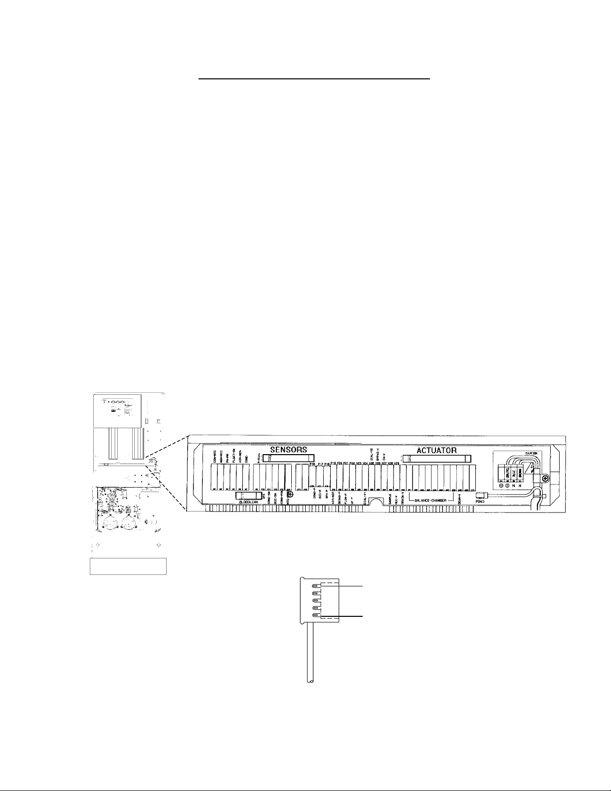
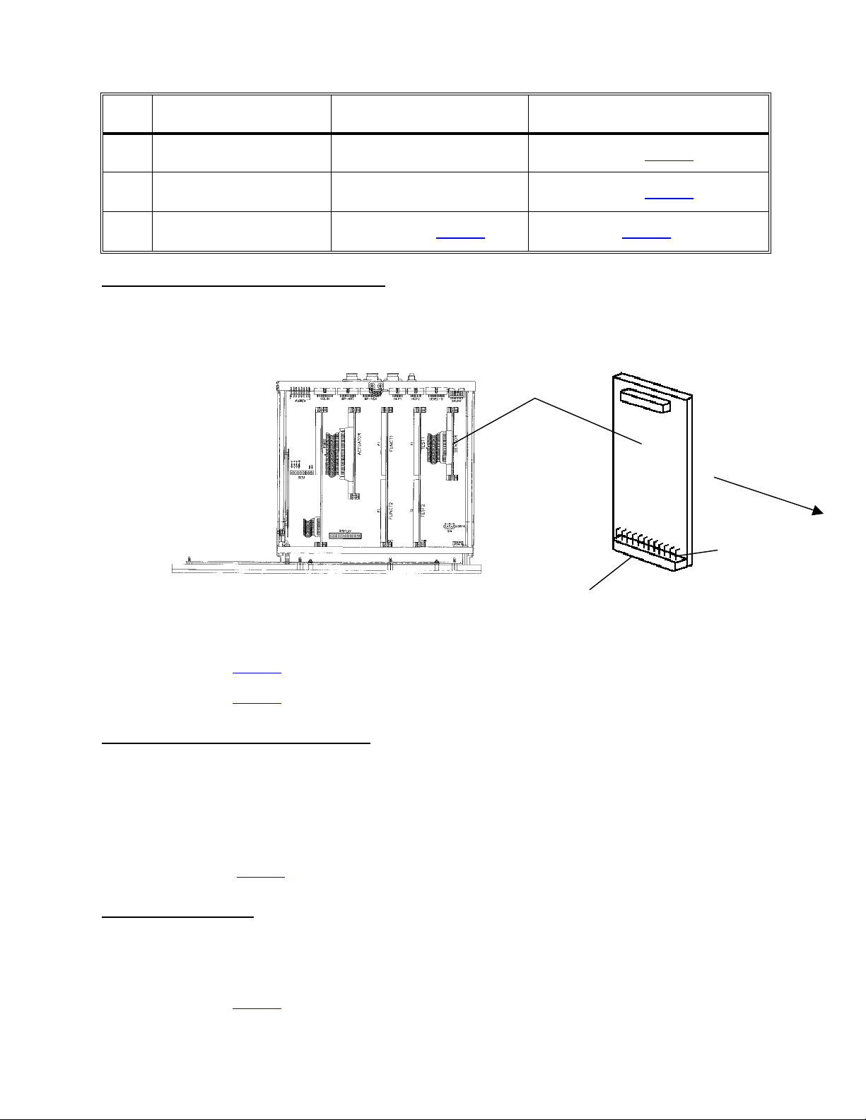
4. Many of the troubleshooting procedures are performed at the DISTRIBUTION BOARD.
a) Inside the distribution board are several numerically identified 'male' connector positions. Male pins are
arranged vertically and are numbered 1 through 5 (from top to bottom).
b) Each hydraulic component has a 5-pin female connector dedicated to numeric distribution board
positions as specified in the HYDRAULIC FLOW DIAGRAM. For example, flow pump #21 plugs into
position [P21, FLOW-P]. Valve 43 plugs into position [V43], etc. Except for the heater, acid pump, and
bicarb pump, you can plug and unplug connectors into the distribution board with the power on.
NOTE: There are several unused positions including; x4 [PH-PR] (pH probe, optional), x13 [COND-POS]
(on-line clearance, optional), x44 [NTC-POS] (on-line clearance, optional), V14, V15, x19 [AIR-SEP], V23
and x40 [V42]. Be CAREFUL not to accidentally plug a connector into one of these.
FEMALE CONNECTOR
DISTRIBUTION BOARD
PIN 1
PIN 5
5. If unsuccessful please call Technical Services at 1-800- 227- 2572.
Fresenius 2008H Troubleshooting Guide
P/N 507082 Rev. B
Page 1
Page 7

THE 'ORDER' OF TROUBLESHOOTING
Troubleshoot in the following order:
1. No Water
2. Flow Errors
3. Temperature
4. Conductivity
5. TMP
6. Blood Leak
7. Pressure Holding Test Failures
NOTE: Before beginning we recommend that you perform INITIAL CHECKS (page 3). This is especially
important if someone has been working on the machine before you!
1. NO WATER (debug screen 5, !WATER = "1" either constantly or intermittently). Without water hydraulic
operation is not possible.
2. FLOW ERRORS (debug screen 5, FLWERR = "1" either constantly or intermittently), will effect
Temperature, Conductivity, TMP and Blood Leak. If a FLOW ERROR is present troubleshoot it before
being concerned with any other alarms.
3. FLOW ERRORS turn the heater off and result in TEMPERATURE problems. Before troubleshooting any
TEMPERATURE problem assure that the machine is free of flow errors (debug screen 5, FLWERR = "0"
constantly).
4. CONDUCTIVITY is temperature compensated. Without stable temperature CONDUCTIVITY will not be
stable. Before troubleshooting CONDUCTIVITY problems, assure that TEMPERATURE is normal and
remaining constant from the main dialysis screen.
5. Before troubleshooting TMP problems assure that there are no flow errors present (debug screen 5,
FLWERR = "0" constantly). Assure also that TEMPERATURE and CONDUCTIVITY are normal and
remaining constant from the main dialysis screen.
6. Before troubleshooting PRESSURE HOLDING TEST FAILURES assure that there are no flow errors
present (debug screen 5, FLWERR = "0" constantly). Assure also that TEMPERATURE and
CONDUCTIVITY are normal and remaining constant from the main dialysis screen.
7. Before troubleshooting BLOOD LEAK problems assure that there are no flow errors present (debug
screen 5, FLWERR = "0" constantly). Assure also that TEMPERATURE and CONDUCTIVITY are normal
and remaining constant from the main dialysis screen.
FUNCTIONAL BOARD SOFTWARE DISCLAIMER
Functional board software may effect the TROUBLESHOOTING GUIDE. With the exception of
CONDUCTIVITY PROBLEMS this guide is compatible with functional software up to 8.02
Page 2
Fresenius 2008H Troubleshooting Guide
P/N 507082 Rev. B
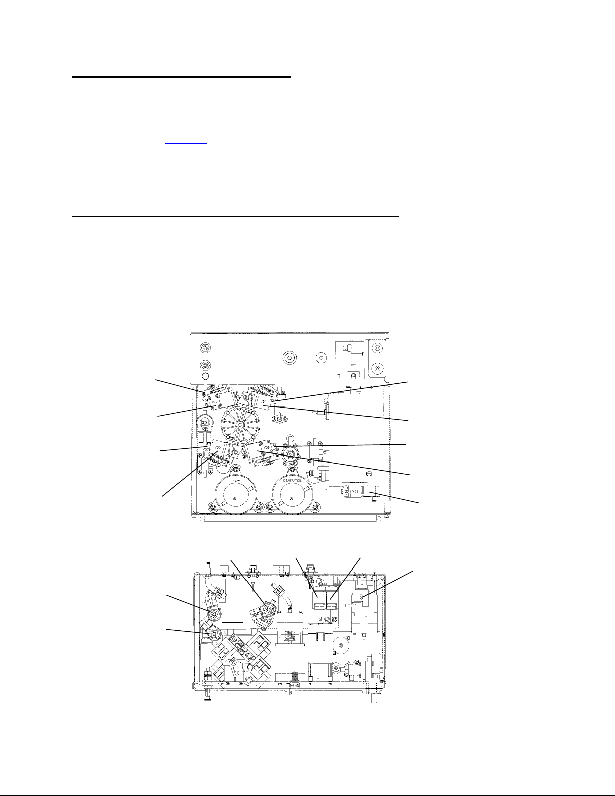
Page 8
INITIAL CHECKS
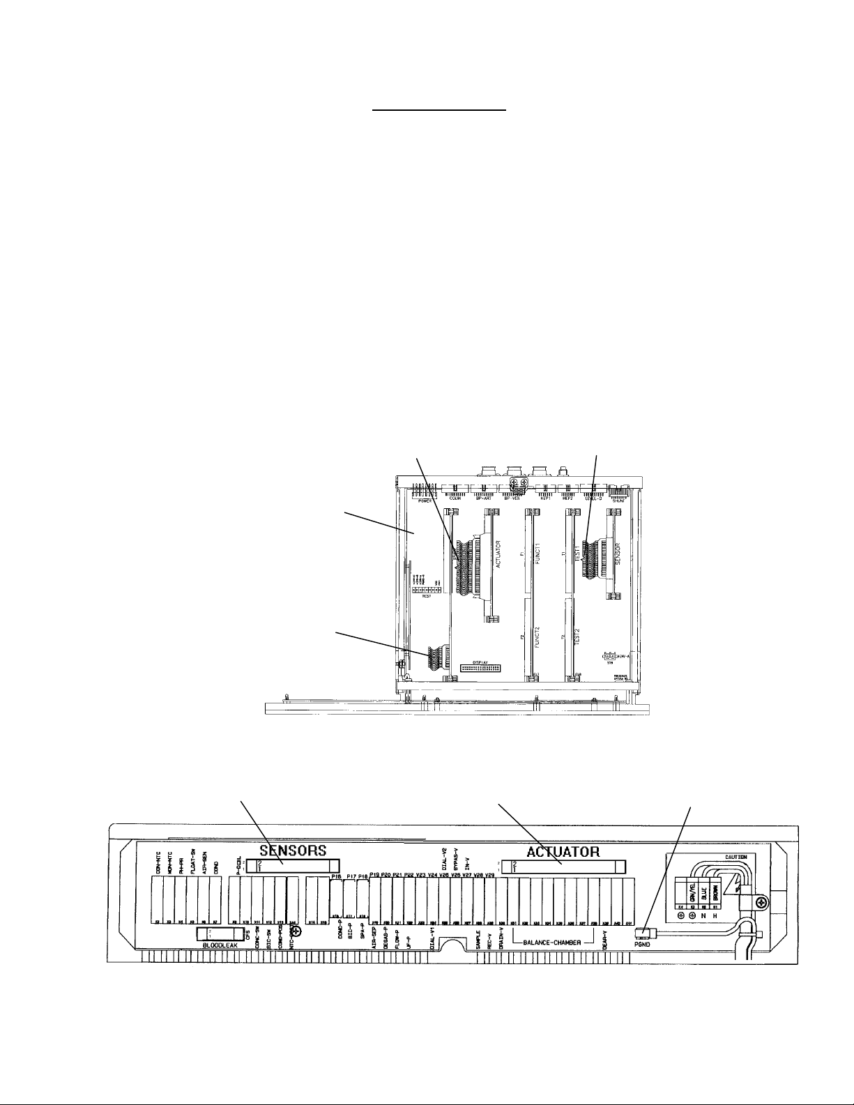
1. Turn the power OFF and slide the card cage forward. Check that all five boards are pushed down into the
motherboard and are 'locked' in.
2. Check that the sensor and actuator cables are plugged tightly into *both ends. Check also for bare wires
or other damage along their entire length.
* Both cables run into the distribution board and terminate at the SENSORS and ACTUATOR connectors
respectively (see DISTRIBUTION BOARD diagram below).
3. Check that the power logic board cable is plugged tightly into the power logic board.
4. Check that the PGND (power ground) wire is plugged into the distribution board (see DISTRIBUTION
BOARD diagram below).
5. Close the card cage. IMPORTANT NOTE! Do NOT troubleshoot with the card cage open! Turn the
machine ON and return to the operating mode (DIALYSIS, RINSE, etc) where the problem is occurring.
6. Allow 10 minutes for stabilization.
ACTUATOR CABLE SENSOR CABLE
MOTHER BOARD
POWER LOGIC
CABLE
CARD CAGE, TOP VIEW
SENSORS CONNECTOR ACTUATOR CONNECTOR PGND WIRE
DISTRIBUTION BOARD
Fresenius 2008H Troubleshooting Guide
P/N 507082 Rev. B
Page 3
Page 9

SAFETY CHECKS
Before placing the machine back into service:
1. Remove all test equipment (jumpers, 'dummy' connectors, etc) from the distribution board and make sure
that all hydraulic components are plugged in.
2. If you have been troubleshooting TEMPERATURE problems turn the heater breaker switch off and
assure that the TEMP display falls to 33°C and that the bypass condition exists.
3. If you have been troubleshooting CONDUCTIVITY problems drop the acid and bicarb lines into water and
assure that the COND display falls to 10.0 and that the bypass condition exists.
4. Check that AUDIO ALARMS are working properly.
5. Perform alarm and pressure holding tests.
EQUIPMENT NEEDED
- Fresenius gauge kit (part # 150034)
- Fresenius test (temperature) 'dummy connectors' (part # 190060)
- Graduated cylinder (1000 ml)
- Buret 0 - 25cc (part # 290104)
- 60 ml syringe
-Flashlight
- Jumper wire
- Independently calibrated temperature, conductivity, and pressure meters
- Voltmeter (recommended Fluke "70" series)
- Clip-on meter leads (recommended Fluke TL24 Flexible test leads with AC80 pin grabbers)
* Non-standard meter probes (recommended Fluke TP80 probes)
* Non-standard meter probes assure safe voltage measurement in 'tight' areas when shorting other pins or
connectors is a concern. Fluke TP80 meter probes include a slip-on cap that fits over the lead to 'isolate'
the measuring point and prevent shorting.
FLUKE TP80 METER PROBES (WITH SLIP ON CAP)
Page 4
Fresenius 2008H Troubleshooting Guide
P/N 507082 Rev. B
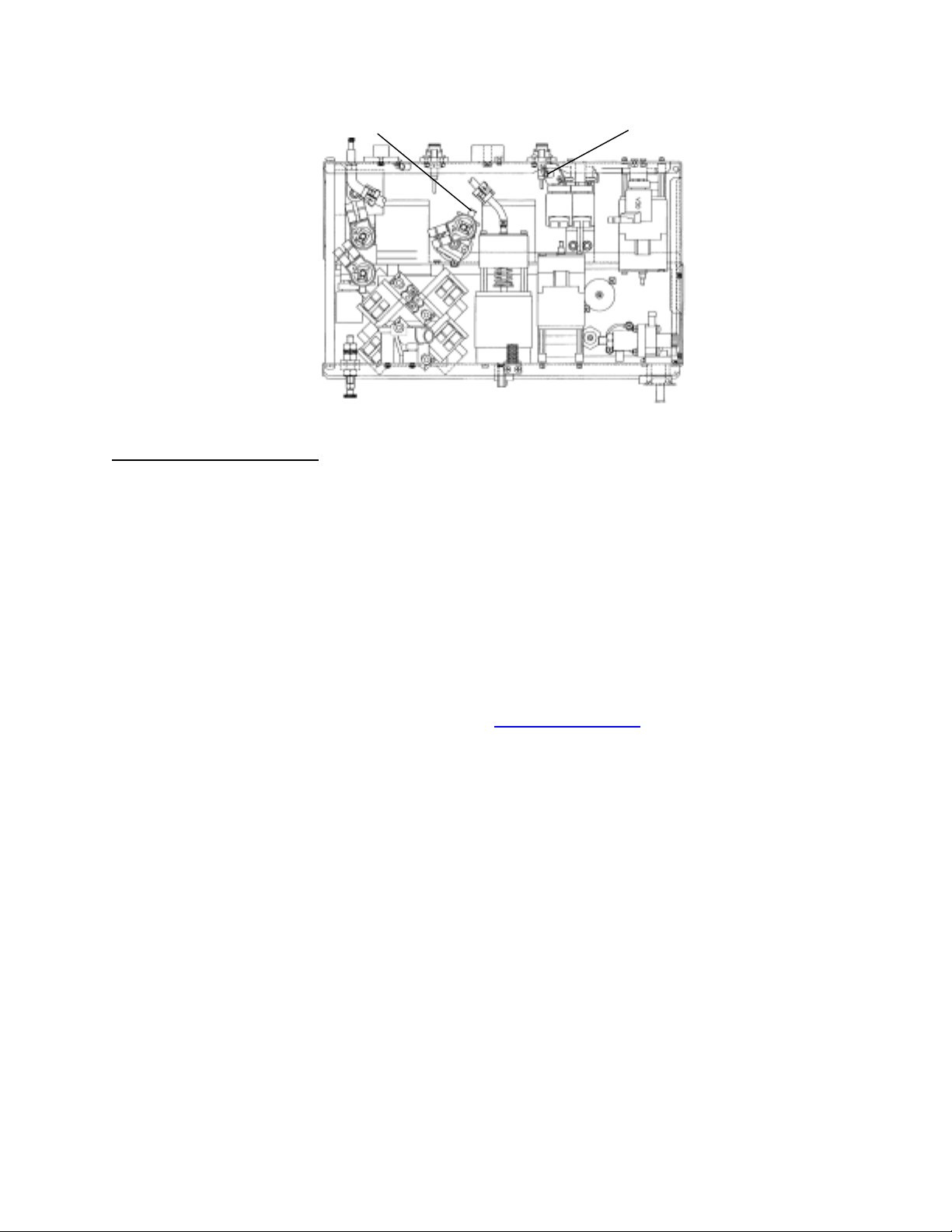
Page 10

UPPER POWER
SUPPLY
SHUNT DOOR
HANSEN
CONNECTORS
EXTERNAL FLOW
INDICATOR #75
DIALYSATE LINE
FILTER #73
UF PUMP #22
BALANCING
CHAMBER #68
HEATER BREAKER
SWITCH
ON/OFF SWITCH
DISTRIBUTION BOARD
(INSIDE COVER)
HEATER
CONNECTOR
INPUT WATER
FILTER
FILTER
VENT LINE
DRAIN LINE
CONDUCTIVITY CELL #7
VALVE #25
Note: On Later version,
Valve 25 may be on the
front side of hydraulics
DIALYSATE PRESSURE
TRANSDUCER #9
REGULATOR #78
FLOW PUMP #21
NTC #2
NTC #3
CFS TRANSDUCER #10
ORIFICE #48
LOADING PRESSURE
REGULATOR #65
VALVE 39
DEAERATION PUMP #29
DIAGRAM A REAR VIEW
Fresenius 2008H Troubleshooting Guide
P/N 507082 Rev. B
Page 5
Page 11
SECTION 1 - FLOW ERRORS IN DIALYZE MODE
F- 1.0.0 CHECK LOADING PRESSURE
a) Assure that the vent tube is not 'pinched' (see diagram A, page 5) .
b) Insert a *loading pressure gauge TIGHTLY into the ACETATE/ACID port. Peak pressure?
1) 0 to 10 psi Call up debug screen 5. If !WATER = "1" proceed to NO WATER (page 23)
otherwise proceed to F- 2.0.0
2) 17 to 25 psi Allow two minutes (if necessary) for the symptoms to appear. See F- 3.0.0
3) Greater than Attempt to calibrate loading pressure to +19 psi peak per CALIBRATION
25 psi PROCEDURES, section 2.13. If not successful a bad loading pressure
regulator #65 is indicated (see diagram A, page 5).
* If the gauge does not read 0 psi at atmosphere compensate for this during loading pressure checks.
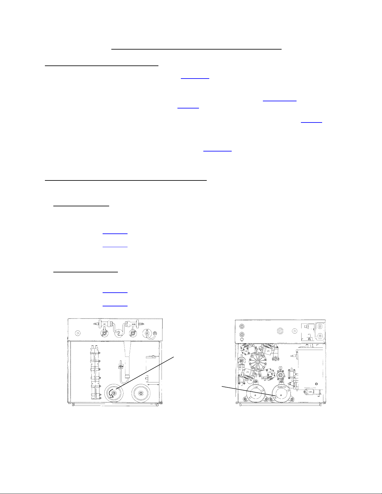
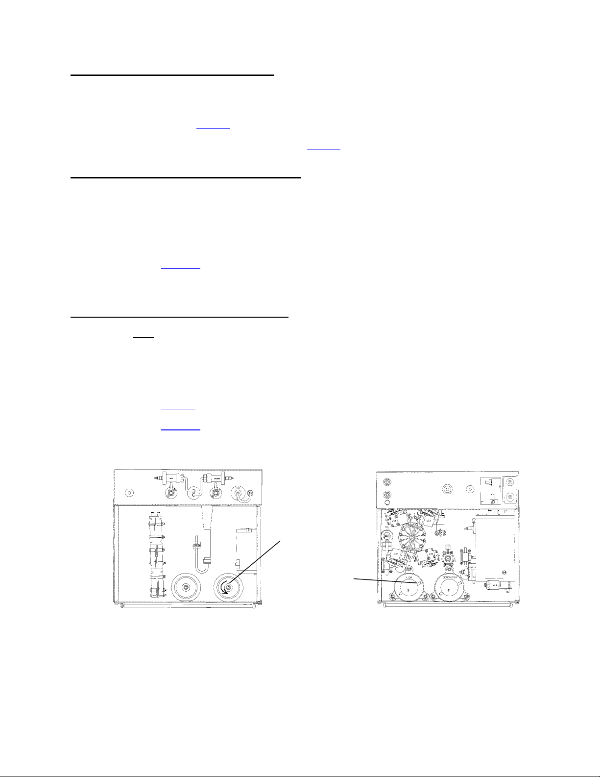
F- 2.0.0 CHECK FOR A RUNNING DEAERATION PUMP
Make sure that flow is on (FLOW ON/OFF LED is off). Depending upon the pump:
1. Motors with brushes The deaeration pump's motor shaft can be accessed from the front side of the
machine (see FRONT VIEW diagram below). If the shaft is *rotating the pump is running. Is the deaeration
pump running?
Yes See F- 14.0.0 (page 12).
No See F- 18.0.0 (page 16) to check the DEAERATION PUMP.
* Rotation is CCW (from the front of the machine). If rotating CW the motor is running backwards
2. Motors without brushes Remove the CLEAR tubing from the deaeration pump's input nozzle (see REAR
VIEW diagram below). If the pump is running you will hear 'gurgling'. Is the deaeration pump running?
Yes See F- 14.0.0 (page 12).
No See F- 18.0.0 (page 16) to check the DEAERATION PUMP.
DEAERATION
MOTOR SHAFT
(WITH BRUSHES)
DEAERATION
INPUT NOZZLE
FRONT VIEW REAR VIEW
Page 6
Fresenius 2008H Troubleshooting Guide
P/N 507082 Rev. B
Page 12
F- 3.0.0 CHECK DEBUG ERRORS
CAUTION Do NOT attempt to reset other alarms during this check!
Call up debug screen 5 and watch !WATER and FLWERR for two minutes. Proceed accordingly:
1) !WATER and FLWERR = "0" constantly. See F- 3.0.1
2) !WATER = "1" constantly or intermittently. See NO WATER (page 23).
3) FLWERR = "1" constantly or intermittently. See F- 4.0.0
F- 3.0.1 FLOW ERROR NOT PRESENT
- If COND is CONSTANTLY high. Watch FLWERR for several minutes. If it goes to "1" see F- 4.0.0
- If COND is drifting from normal to high. Wait until the BYPASS LED is off and watch FLWERR for 30
seconds. If it goes to "1" see F- 6.0.0.
- If conductivity remains normal. If FLWERR remains " 0" constantly a flow error is not indicated.
- If conductivity remains low and FLWERR remains "0" a flow error is NOT present.
F- 4.0.0 CHECK FOR FILLING PROGRAM
Call up debug screen 7. Is FILACT "1" or "0"?
"1" See F- 4.0.1
"0" See F- 5.0.0
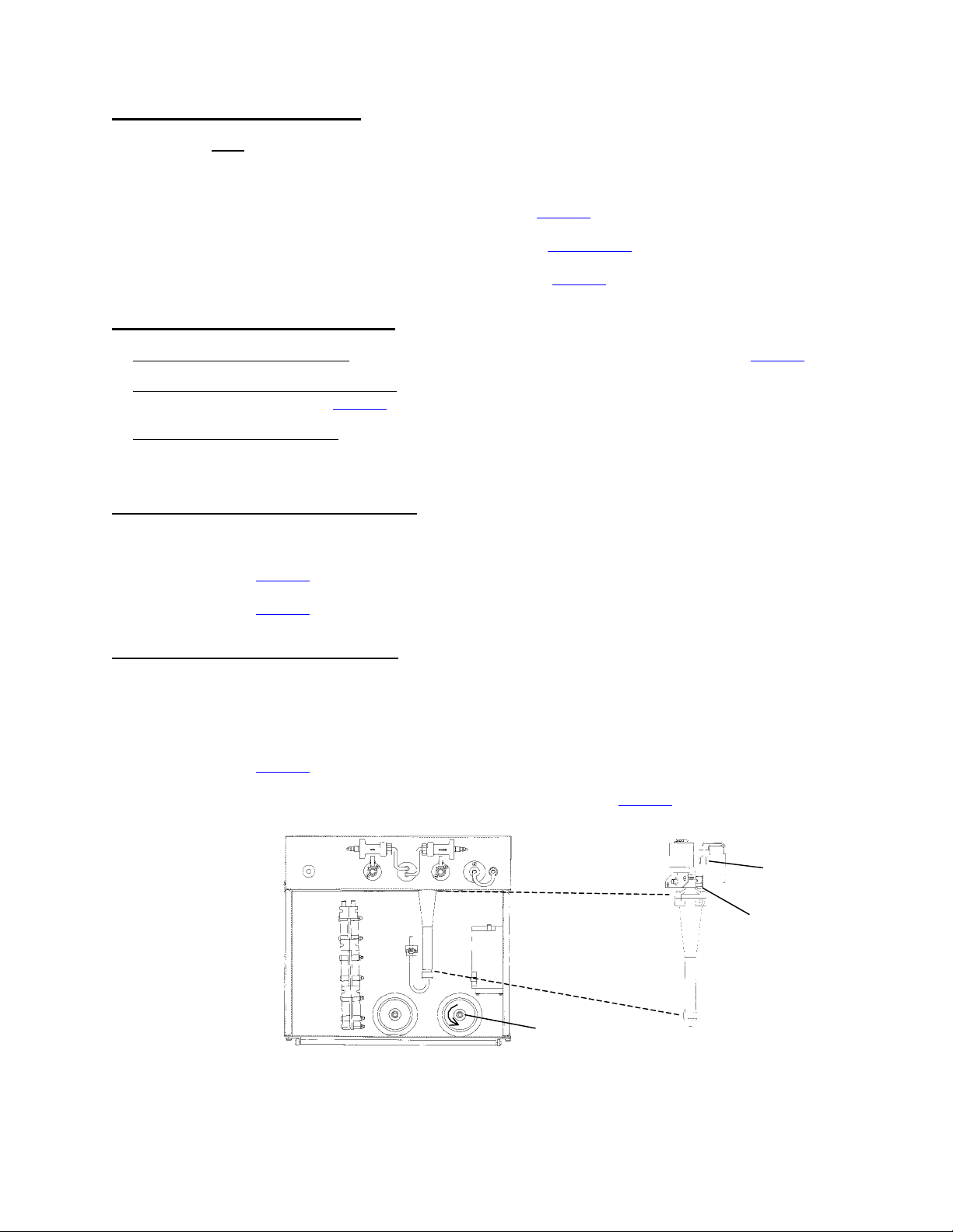
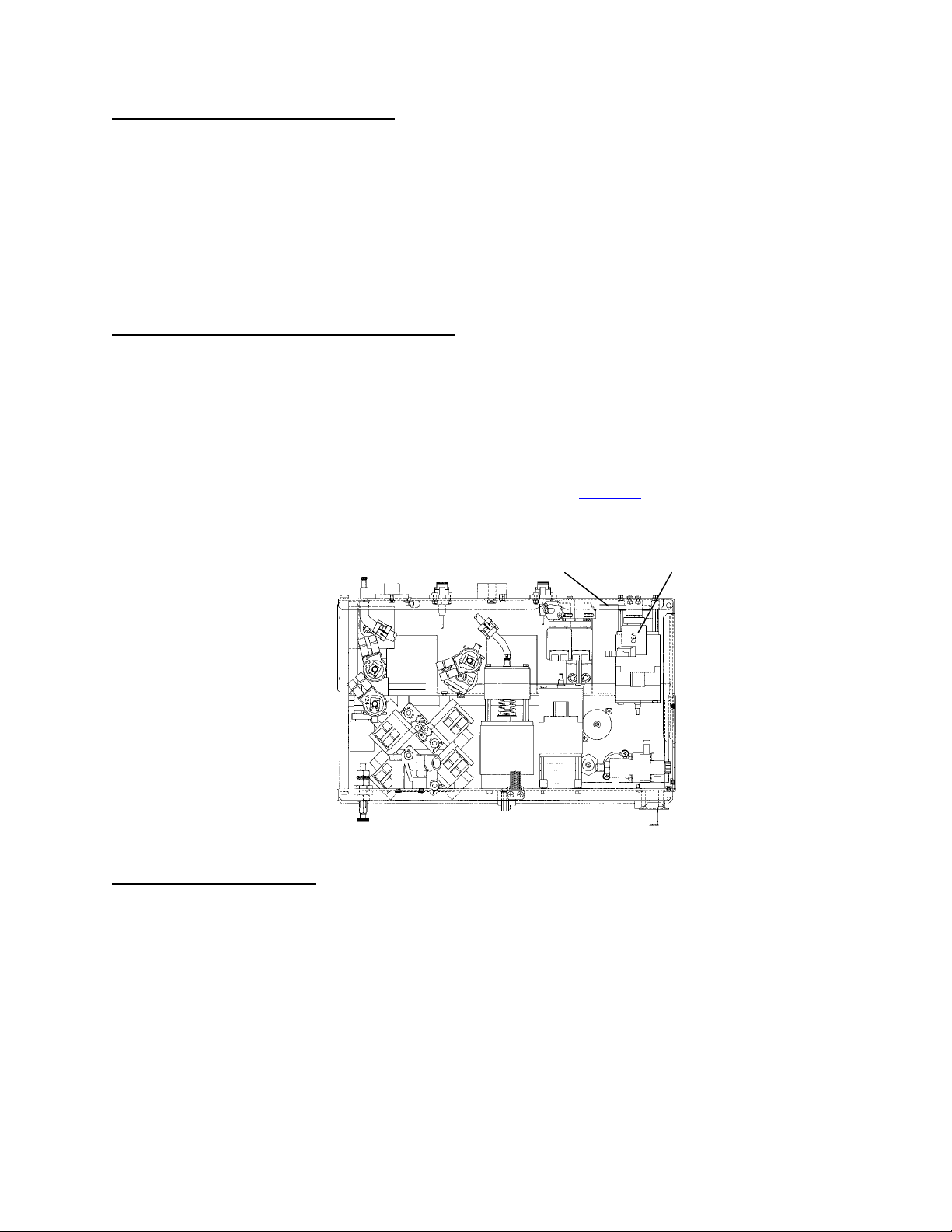
F- 4.0.1 FILLING PROGRAM PRESENT
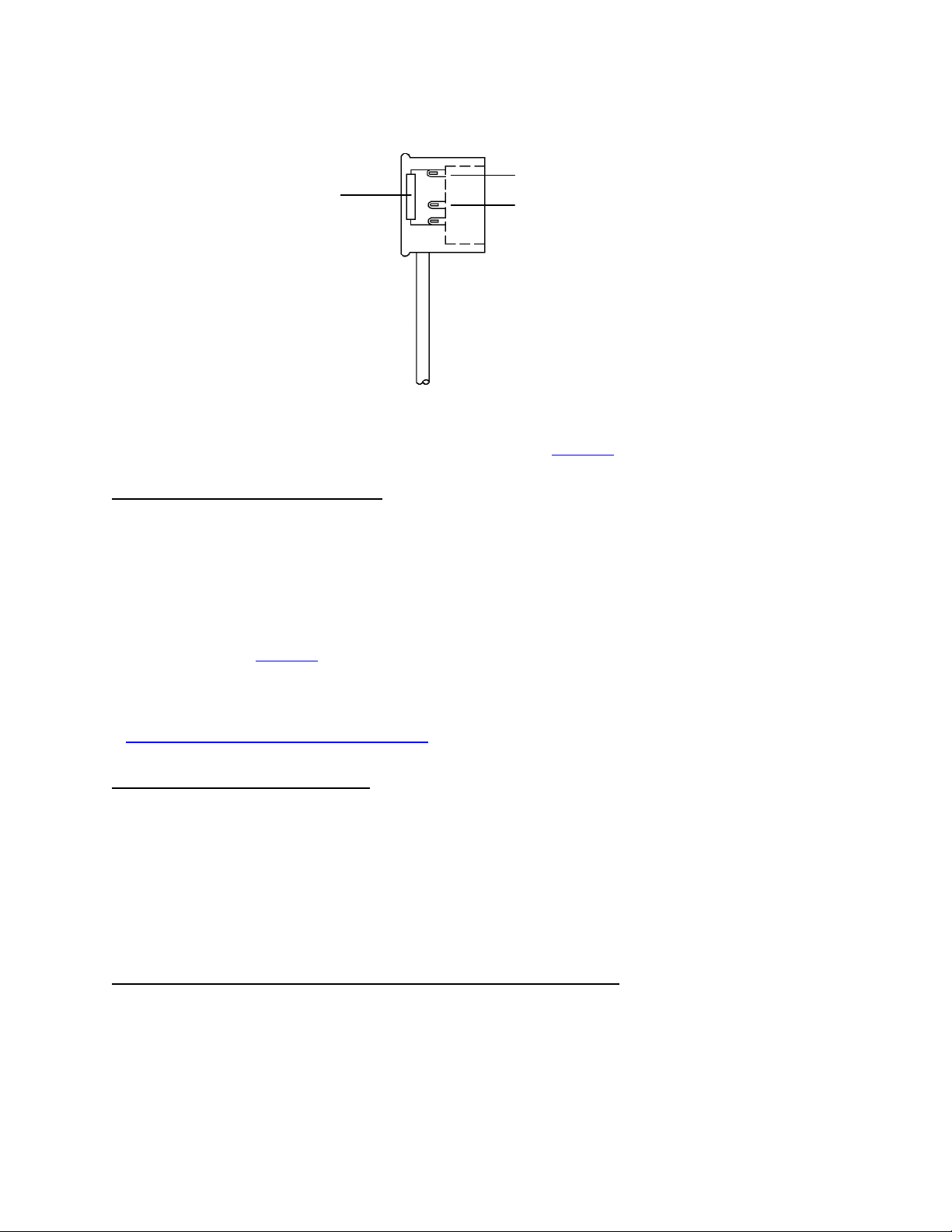
a) At the top of chamber #69 is a two-pin female connector that plugs onto two male probes (see diagram,
below). Unplug both sides of the connector and connect the female ends together. FILACT should now = 0.
b) Return to debug screen 5 and watch for 3 minutes. Does FLWERR go to "0" and REMAIN?
Yes See F- 4.0.2.
No Plug the female connector back onto the probes and see F- 5.0.0.
TWO-PIN FEMALE
CONNECTOR
MALE PROBES
CHAMBER # 69
FLOW PUMP
MOTOR SHAFT
FRONT VIEW
Fresenius 2008H Troubleshooting Guide
P/N 507082 Rev. B
Page 7
Page 13

F- 4.0.2 CHECK FLOW PUMP
From the front side of the machine you can see the flow pump's motor shaft (see FRONT VIEW diagram,
previous page). Turn the flow off. Is the shaft rotating?
Yes Replace the actuator board.
No See F- 16.0.0 (page 14).
F- 5.0.0 CHECK FOR A *VALVE ERROR
Proceed with this step ONLY if FILACT and !WATER are both = "0" continuously.
From DIALYZE MODE return to debug screen 5. Watch VLVERR VERY carefully for two full minutes. If a
valve error is present VLVERR 'blinks' momentarily to "1" (about every 60 seconds). If a valve error is present
VLVERR goes to "1" for ONLY a second. If you look away you may miss it! Does VLVERR ever 'blink' "1"?
Yes See F- 5.0.1
No See F- 6.0.0
* VALVE ERRORS indicate either high or low current in a particular 'valve circuit'.
F- 5.0.1 LOCATING THE VALVE ERROR
Listen carefully in the area of the hydraulics (you may need to remove them from the machine). You should
be able to hear a continuous, dull, 'thudding'. Proceed step-by-step and follow the given instructions.
1) From DIALYZE MODE open the shunt door. If the 'thudding' stops a VALVE 25 is causing the error. Note
this (valve 25 is the problem) and see TROUBLESHOOTING VALVE ERRORS (page 30). If the 'thudding'
continues proceed to step 2.
2) Turn the flow off. If the 'thudding' stops a BALANCING CHAMBER VALVE is causing the error. Note this
(balancing chamber valve is the problem) and see TROUBLESHOOTING VALVE ERRORS (page 30). If
the 'thudding' continues proceed to step 3.
3) The 'thudding' continues with the shunt door open and flow off. VALVE 30 or 26 is causing the error. Note
this (valve 30 or 26 is the problem) and see TROUBLESHOOTING VALVE ERRORS (page 30).
Troubleshoot BOTH valves.
Page 8
Fresenius 2008H Troubleshooting Guide
P/N 507082 Rev. B
Page 14
F- 6.0.0 CHECK FLOW ERROR 'IN BYPASS'
Open the shunt door to cause bypass. Return to debug screen 5 and watch FLWERR for one full minute.
Does FLWERR go to "0" constantly or does it still = "1" (either constant or intermittent)?
"0" constantly See F- 6.0.1
Still = "1" Close the shunt door and see F- 7.0.0
F- 6.0.1 CHECK FLOW ERROR 'OUT OF BYPASS'
a) Leave the shunt door open and return to the main DIALYSIS screen.
b) Allow TEMP and COND to become normal.
c) Close the shunt door (bypass LED should turn off) and return to debug screen 5. Wait 30 seconds. Does
FLWERR = "1"?
Yes See F- 17.0.0 (page 15).
No A flow error is not indicated.
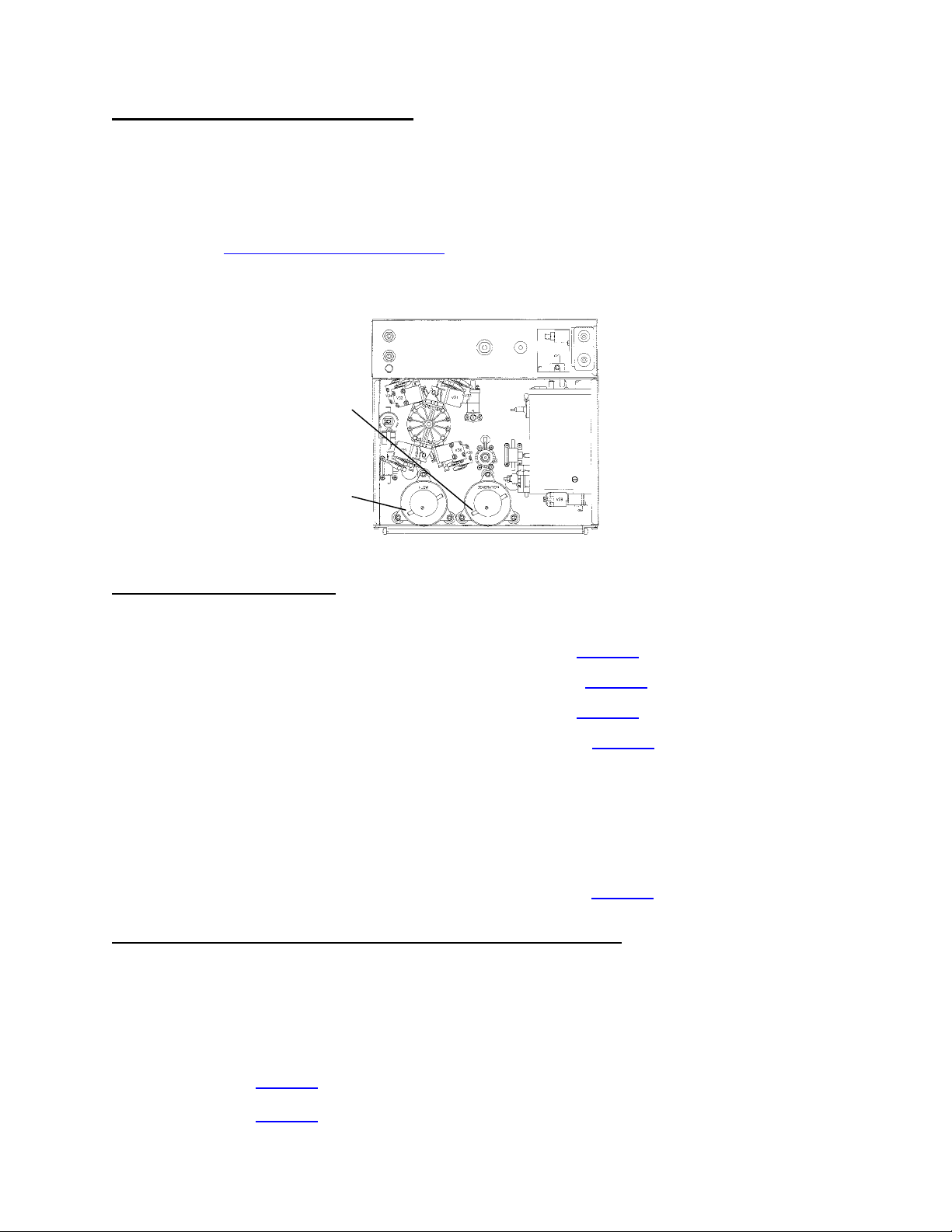
F- 7.0.0 CHECK FOR A RUNNING FLOW PUMP
CAUTION Do NOT attempt to reset other alarms during this check!
a) At this time NOTE if FLWERR = "1" constantly or intermittently for future use.
b) From the FRONT of the machine you can see the flow pump's motor shaft (see FRONT VIEW diagram
below). If the shaft *rotating?
Yes See F- 8.0.0
No See F- 18.0.0 (page 16) to check the FLOW PUMP.
* Rotation is CCW (from the front of the machine). If rotating CW the motor is running backwards
FLOW PUMP
MOTOR SHAFT
FLOW PUMP
OUTPUT NOZZLE
FRONT VIEW REAR VIEW
Fresenius 2008H Troubleshooting Guide
P/N 507082 Rev. B
Page 9
Page 15

F- 8.0.0 CHECK FLOW PUMP CONTROL
Turn the flow off and check the flow pump's motor shaft again. Still rotating?
Yes Replace the actuator board (pump driver (IC18) possibly shorted).
No a) Turn the flow on.
b) FLWERR may = "0" for a few seconds after turning flow on. Ignore this! As noted
previously (step F- 7.0.0) was FLWERR = "1" constant or intermittent?
Constant See F- 10.0.0
Intermittent See F- 9.0.0
F- 9.0.0 CHECK FOR NO WATER
Turn the flow on and call up debug screen 5 and carefully watch !WATER for two minutes. Does !WATER go
to "1" at any time during this time interval?
Yes See NO WATER (page 23).
No See F- 9.0.1
F- 9.0.1 CHECK FLOW PUMP PRESSURE
a) Tee a pressure gauge between the flow pump's output nozzle and the WHITE tubing (see REAR VIEW
diagram, previous page).
b) Turn the flow on at a 500 flow rate. Does pressure peak to 14 psi or greater?
Yes See F- 13.0.0 (page 12)
No Three possibilities: 1) Bad actuator board; 2) Bad flow pump head; 3) Bad flow pump motor.
F- 10.0.0 CHECK DRAIN FLOW
a) Having a bucket handy and go to end of the drain line. Hold it UP, at a 45 degree angle, over the bucket.
CAUTION! Holding the drain line lower than 45 degrees makes this test invalid!
b) Watch for 20 seconds. Flow may be intermittent and this is normal. Is there any flow through the drain line?
Yes See F- 10.1.0
No See F- 11.0.0
Page 10
Fresenius 2008H Troubleshooting Guide
P/N 507082 Rev. B
Page 16
F- 10.1.0 DETERMINING DRAIN FLOW
Normal Fresenius drain output 'pulses' in 30 ml increments, stops completely, and then 'pulses' out again. Is
drain flow 'pulsing' or 'continuous' (never stops)?
Pulsing See F- 13.0.0 (next page).
Continuous Three possibilities: 1) Partial restriction to drain (check the drain line first for
restrictions); 2) Balancing chamber valve remaining open (run automated valve leak
test from SERVICE/DIAGNOSTICS); 3) Leaking balancing chamber diaphragm (see
TESTING FOR A LEAKING BALANCING CHAMBER DIAPHRAGM).
F- 11.0.0 CHECK FLOW TO (DRAIN) VALVE 30
CAUTION! During this procedure there will be spillage. Move the hydraulics away from the cabinet to prevent
spillage into the cabinet!
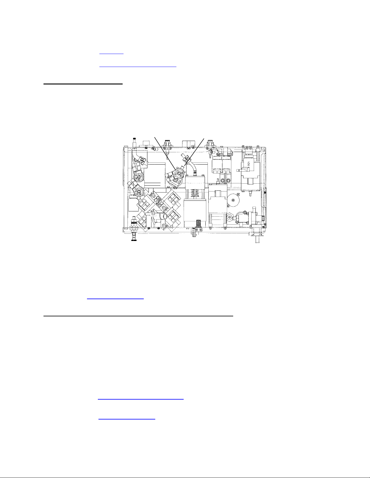
a) Turn the flow off and remove the INPUT tube from valve 30 (see TOP VIEW diagram below). Point it AWAY
from the hydraulics.
b) Turn the flow on. Is there good 'pulsing' flow here?
Yes Turn flow off and attach the tubing to valve 30. See F- 11.1.0
No See F- 12.0.0
VALVE 30INPUT TUBE
TOP VIEW
REAR OF MACHINE
F- 11.1.0 CHECK VALVE 30
a) Turn the flow on.
b) Remove the drain line from the back of the machine. Is there good 'pulsing' flow here?
Yes The drain line is restricted.
No A problem is indicated with VALVE 30 or the actuator board. NOTE this and see
TROUBLESHOOTING VALVES (page 29).
Fresenius 2008H Troubleshooting Guide
P/N 507082 Rev. B
Page 11
Page 17
F- 12.0.0 CHECK FLOW TO FLOW PUMP
Proceed with this step if you are VERY sure that VLVERR (debug screen 5) is always "0".
Place the machine into RINSE and remove the CLEAR tube from the flow pump's INPUT nozzle (see diagram
below). Good flow here?
Yes A problem is indicated with VALVE 26 or the actuator board. NOTE this and see
TROUBLESHOOTING VALVES (page 29).
No Replace the actuator board. If the flow error continues there may be two bad valves
(remaining closed) on the balancing chamber.
DEAERATION PUMP
INPUT NOZZLE
FLOW PUMP
INPUT NOZZLE
REAR VIEW
F- 13.0.0 CHECK CFS SIGNAL
Making sure that flow is on call up debug screen 11 and watch ACFS (in vdc). SIX possibilities:
1) Constant flow error and ACFS remaining between 3 and 7. See F- 21.0.0 (page 20).
2) Constant flow error and ACFS remaining between 8 and 11. See F- 23.0.0 (page 22).
3) Constant flow error and ACFS remaining between 0 and 3. See F- 20.0.0 (page 18).
4) Intermittent flow error and ACFS remaining between 3 and 7. See F- 21.0.0 (page 20).
5) Intermittent HIGH FLOW error. Call up debug screen 10 and watch CFS for a couple of minutes. If CFS
intermittently 'bounces' to about 10 replace the CFS transducer (#10). If the problem continues check for a
bad connection at the sensor board cable on both sides (especially the distribution board side, unplug the
cable and check the male pins for corrosion ). There may also be an intermittent open in the sensor cable or
a problem with the sensor or actuator boards.
6) Intermittent flow error and ACFS 'bouncing' (about every 9 seconds) from between 0 and 3 to about 5. A
problem is indicated with a BALANCING CHAMBER VALVE. See F- 19.0.0 (page 16).
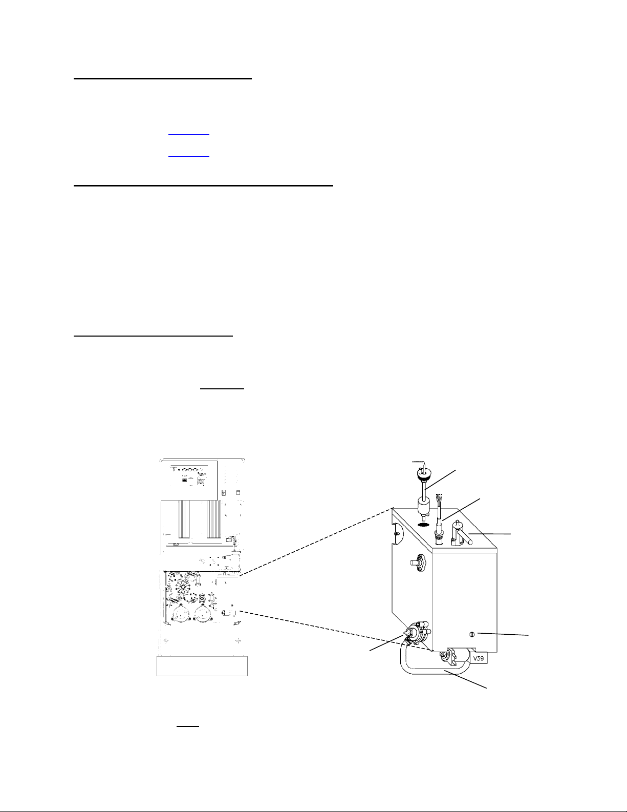
F- 14.0.0 LOW LOADING PRESSURE, DEAERATION PUMP RUNNING
NOTE: This procedure checks for water in the hydroblock and proper float functional.
a) Stop the deaeration pump by unplugging it from distribution board position P20, DEAR-P.
b) If you haven't done so remove the CLEAR (input) tube from the deaeration pump's nozzle (see REAR VIEW
diagram, above). Is there flow from the tube?
Page 12
Yes See F- 14.0.1
No See F- 15.0.0
Fresenius 2008H Troubleshooting Guide
P/N 507082 Rev. B
Page 18
F- 14.0.1 CHECK INCOMING WATER
Allow this flow to continue for about three minutes (you may need a bucket). You should hear water entering
the hydroblock in cycles as the float falls and rises. Does flow remain continuous?
Yes See F- 14.0.2
No See F- 15.0.0
F- 14.0.2 CHECK LOADING PRESSURE REGULATOR
a) Plug the deaeration pump back into the distribution board (P20, DEAR-P) and assure that it starts running
i.e. the motor shaft rotates. Allow one minute and check if loading pressure returns to normal (19 ± 1 psi). If
it does there may be an intermittent problem with the float. Continue to part b otherwise.
b) Tightly clamp the solid tubing between the loading pressure regulator and the hydroblock (see diagram
below). Is there a drastic increase of loading pressure?
Yes A problem is indicated with the loading pressure regulator.
No A problem is indicated with the deaeration pump head.
F- 15.0.0 CHECK HYDROBLOCK
a) Clamp the vent tube and remove the orifice from the hydroblock (see diagram below). Check if it is plugged.
If plugged this is the problem.
b) Re-install the orifice and REMOVE the clamp from the vent tube.
c) Turn the power off.
d) Loosen (but don't remove) the screws that mounts the float into the hydroblock (see diagram below).
CAUTION Don't pull on the float's wiring harness or you may break it! Carefully remove the float from the
hydroblock.
FLOAT (FULLY DOWN ON SHAFT)
HEATER
VENT TUBE
HYDROBLOCK
LOADING PRESSURE
REGULATOR
SOLID TUBING
(CLAMP HERE)
ORIFICE
e) Unplug the float from distribution board position FLOAT-SW. Check inside the distribution board for bent
broken or corroded male pins.
Fresenius 2008H Troubleshooting Guide
Page 13
P/N 507082 Rev. B
Page 19
f) Very carefully open the cover on the female connector (see diagram below). Note that pins 2 and 5 are
(
)
missing. Clip meter leads onto pins 1 and 3 (pin 1 = top of the 100 ohm resistor, pin 3 = middle pin).
CAUTION! Be careful to clip onto the correct pins!
PIN 1 (TOP PIN)
100 OHM RESISTOR
PIN 2 (MISSING)
PIN 3 (MIDDLE PIN)
MISSING
PIN 5
FEMALE FLOAT DISTRIBUTION
BOARD CONNECTOR
g) With the float FULLY DOWN on the shaft you should read approximately 100Ω, FULLY UP an 'open' (OL).
Move the float FULLY UP and DOWN twenty times while watching the transition on the meter. It should go
from OL to 100Ω everytime! If the float checks out good see F- 15.0.1
F- 15.0.1 CHECK INCOMING WATER
a) Plug the float's connector back into the distribution board (position FLOAT-SW).
b) Hold the float in its FULLY UP position. Turn the power on and wait until the SELECT PROGRAM screen is
up.
c) Looking into the hydroblock's float cavity turn the power on. CAUTION Avoid overflow during this step!
Move the float to its FULLY DOWN position. Is the water level rising?
Yes See F- 15.0.2
No Two possibilities: 1) *Bad sensor board cable; 2) Bad actuator board.
* The sensor cable can be checked for continuity. Note that you are checking the FLOAT connection and see
CHECKING THE SENSOR BOARD CABLE (page 74).
F- 15.0.2 CLEARING AN AIR LOCK
a) Connect a 60 ml syringe to the clear INPUT tubing of the deaeration pump and draw on it. You may have to
pull five or six syringes full of air before water flows continuously by itself. If you are not able to make water
flow continuously it may be indicative of a 'stripped' orifice.
b) Re-connect the INPUT tubing to the deaeration pump and plug the deaeration pump back into the
distribution board (P20, DEAR-P). Assure that it starts running i.e. the motor shaft rotates. Allow a few
minutes for loading pressure to return to normal. NOTE: Recurring air locks may be indicative of a bad
deaeration pump head, motor or a 'stripped' orifice.
F- 16.0.0 TROUBLESHOOTING 'FILLING PROGRAM' FLOW ERRORS
During FILLING PROGRAMS the dialysate pressure transducer #9 determines the presence of flow.
a) Plug the connector back onto the probes.
b) Remove the dialysate lines from the shunt door and drop them into a bucket of water on the floor.
c) IMPORTANT Close the shunt door.
Page 14
Fresenius 2008H Troubleshooting Guide
P/N 507082 Rev. B
Page 20
d) Call up debug screen 9 and wait 30 seconds. Is PDIA between 4.0 and 6.0 vdc?
Yes See F- 16.0.1
No See TM- 2.0.1, TMP PROBLEMS (page 58).
F- 16.0.1 CHECK VALVE 43
CAUTION! During this procedure there will be spillage. Move the hydraulics away from the cabinet to prevent
damage.
a) Place the machine into RINSE.
b) Clamp and remove the tubing from the valve 43's output nozzle (see diagram below).
VALVE 43
OUTPUT NOZZLE
HYDRAULICS, TOP VIEW
c) Call up debug screen 20. When V43= 1 the actuator board is sending a signal to open valve 43. This occurs
every two minutes for several seconds. When V43= 1 is there flow from valve 43's nozzle?
Yes Flow errors sometimes occur if a FILLING PROGRAM is prolonged.
No A problem is indicated with VALVE 43 or the actuator board. NOTE this and see
CHECKING VALVES (page 28).
F- 17.0.0 TROUBLESHOOTING FLOW ERRORS 'OUT OF BYPASS'
A problem is indicated in the 'out of bypass' circuit which includes the external dialysate filter (73), valves 24
and 25. CAUTION! There will be spillage during this procedure. Make sure the card cage is closed!.
a) Place the machine into RINSE.
b) Open the shunt door and remove the RED dialysate line. Is there flow from the shunt door?
Yes a) Stop RINSE by pulling the red concentrate connector from its port
b) Check the external dialysate line filter #73 (see diagram A, page 5). If the filter is clean a
problem is indicated with VALVE 25 or the actuator board. NOTE this and see
TROUBLESHOOTING VALVES (page 29).
No A problem is indicated with VALVE 24, the actuator board or actuator cable. NOTE this and
see CHECKING VALVES (page 28).
Fresenius 2008H Troubleshooting Guide
P/N 507082 Rev. B
Page 15
Page 21
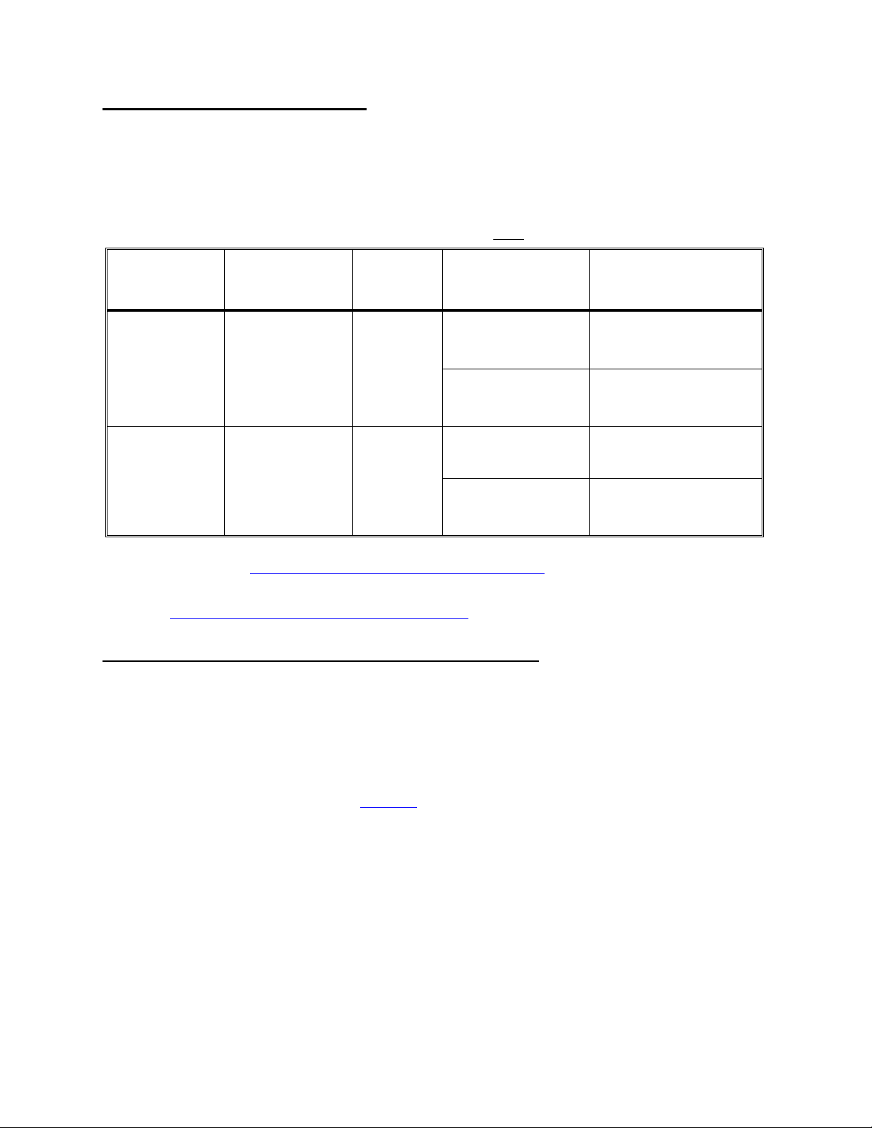
F- 18.0.0 TROUBLESHOOTING PUMPS
Proceed ONLY with the pump of interest.
a) Make sure that flow is on and the proper flow rate is selected as directed in the table below.
b) Unplug the noted pump from the distribution board. Check, inside the distribution board, for bent, broken,
or corroded male pins.
c) Measure dc voltage, inside the distribution board, between male pins 1 and 5 (top and bottom).
PUMP
DISTRIBUTION
BOARD
POSITION
FLOW
RATE
(ml/min)
VOLTAGE
RANGE
BAD
16 vdc or greater Replace the pump head
DEAERATION P20, DEGAS-P 500
Two Possibilities:
Less than 16 vdc
1
1.
Actuator cable
2. Actuator board
12 vdc or greater Replace the pump head
FLOW P21, FLOW-P 800
Less than 12 vdc
Two Possibilities:
2
1.
Actuator cable
2. Actuator board
1
The actuator cable can be checked for continuity. Note that you are checking DEAERATION PUMP
connections and see CHECKING THE ACTUATOR BOARD CABLE (page 72).
2
The actuator cable can be checked for continuity. Note that you are checking FLOW PUMP connections
and see CHECKING THE ACTUATOR BOARD CABLE (page 72).
F- 19.0.0 TROUBLESHOOTING BALANCING CHAMBER VALVES
A balancing chamber valve may be remaining open or closed at all times.
a) Check that all balancing chamber valves are plugged into the distribution board at their proper positions
(V31 through V38). If ok proceed.
b) Turn the power off and swap in a good actuator board.
c) Put the machine back into dialyze mode. Call up debug screen 5 and watch FLWERR for several minutes.
If the flow error is still intermittent see F- 19.0.1.
Page 16
Fresenius 2008H Troubleshooting Guide
P/N 507082 Rev. B
Page 22

VALVE 34
(BEHIND VALVE 32)
VALVE 32
VALVE 33
(BEHIND VALVE 31)
VALVE 31
VALVE 37
(BEHIND VALVE 35)
VALVE 35
(BEHIND VALVE 36)
HYDRAULICS, REAR VIEW
F- 19.0.1 CHECKING VALVES 36 AND 38
NOTE: The previous actuator board is good.
a) Turn the machine off and then back on. Wait until the SELECT PROGRAM screen is up.
b) IMPORTANT! Do NOT place the machine into dialyze mode. From SELECT PROGRAM is there flow to the
drain?
Yes Using a metal clamp tightly clamp the solid tubing at balancing chamber valve 36 (see
diagram, above). If flow stops replace valve 36. If not replace valve 38.
VALVE 36
VALVE 38
No See F- 19.0.2
F- 19.0.2 CHECKING VALVE 32
Unplug valves 32 and 36 from the distribution board (V32 and V36). Plug 36 into 32's position and visa versa.
If there is flow to the drain replace valve 32. If not carefully plug both valves back into their proper distribution
positions and see F-19.0.3
F- 19.0.3 CHECKING VALVE 34
Unplug valves 34 and 38 from the distribution board (V34 and V38). Plug 34 into 38's position and visa versa.
If there is flow to the drain replace valve 34. If not carefully plug both valves back into their proper distribution
board positions and see F-19.0.4.
Fresenius 2008H Troubleshooting Guide
Page 17
P/N 507082 Rev. B
Page 23

F- 19.0.4 CHECKING FOR CLOSED BALANCING CHAMBER VALVES
Place the machine into dialyze mode and TIGHTLY clamp the clear tubing at valve 31 (see diagram, above).
From debug screen 5, does FLWERR now go constant "1"?
Yes Referencing the flow diagram, the problem is a valve in the right-side balancing chamber.
See F- 19.0.5
No FLWERR remains intermittent. Referencing the flow diagram, the problem is a valve in the
left-side balancing chamber. See F- 19.0.6
F- 19.0.5 'RIGHT-SIDE' VALVE BAD
a) Turn the power off and unplug valves 37 and 34 from the distribution board (positions V37 and V34).
b) Plug valve 37 into 34's position (V34), leaving valve 34 unplugged.
c) IMPORTANT! Do NOT place the machine into dialyze mode. From SELECT PROGRAM check drain flow.
Is there strong flow to the drain?
Yes Note that either valve 38 or 34 is not opening and see F- 19.0.7
No Note that either valve 37 or 33 is not opening and see F- 19.0.7
F- 19.0.6 'LEFT-SIDE' VALVE BAD
a) Turn the power off and unplug valves 35 and 32 from the distribution board (positions V35 and V32).
b) Plug valve 35 valve 32's position (V32), leaving valve 32 unplugged.
c) IMPORTANT! Do NOT place the machine into dialyze mode. From SELECT PROGRAM check drain flow.
Is there strong flow to the drain?
Yes Note that either valve 32 or 36 is not opening and see F- 19.0.7
No Note that either valve 35 or 31 is not opening and see F- 19.0.7
F- 19.0.7 CHECK FOR A 'MECHANICALLY STICKING' VALVE
a) Check the noted valve's distribution board connector position for bent, broken or corroded male pins.
b) Carefully plug all valves back into their proper distribution board position.
c) Place the machine into dialyze mode and call up debug screen 7. FILACT MUST = "0" to continue.
d) If the valve bodies are clear check the valve plungers for movement and replace the one that is not moving.
If the valve bodies are solid, swap one of the valves and check for flow errors.
F- 20.0.0 ACFS BETWEEN 0 AND 3
The CFS transducer is acting like a 'short'. Turn flow off. Does ACFS go to between 3 and 7?
Yes IMPORTANT turn flow on and return to F- 7.0.0 (the CFS transducer is good).
Page 18
No See F- 20.0.1
Fresenius 2008H Troubleshooting Guide
P/N 507082 Rev. B
Page 24

F- 20.0.1 CHECK CFS CIRCUIT
Unplug the CFS transducer from the distribution board (position CFS). Check, for bent, broken or corroded
male pins. Is ACFS between 8 and 11?
Yes See F- 20.0.2
No ACFS remains between 0 and 3. See F- 20.0.7
F- 20.0.2 CHECK SENSOR BOARD CFS VALUE
Leave the transducer unplugged and call up debug screen 10. Is CFS between 8 and 11?
Yes See F- 20.0.3
No Replace the sensor board.
F- 20.0.3 CHECK FOR A LEAKING BALANCING CHAMBER VALVE
a) Plug the CFS transducer back into the distribution board and assure that ACFS returns to between 0 and 3.
b) Turn the flow on and push SET to return to the DIALYSIS screen. Is TMP pegged at +60?
Yes See F- 20.0.4
No Replace the CFS transducer (see diagram, next page).
F- 20.0.4 CHECK FOR A LEAKING BALANCING CHAMBER VALVE
a) Push and release the RESET button on the front panel. The message "ADJUST TMP?" appears.
b) Immediately push and HOLD the RESET button. After the "ADJUSTING TMP" message is gone does TMP
return to +60 or remain relatively stable?
+60 See F- 20.0.5
Stable Replace the CFS transducer (see diagram, next page).
F- 20.0.5 CHECK FOR A LEAKING BALANCING CHAMBER VALVE
a) Place the machine into SERVICE/DIAGNOSTICS.
b) Select and enter #11 VALVE LEAK TEST. Wait until the "READY" message appears.
c) Push SET TWICE to start the test. Is a leaking valve indicated?
Yes Note the leaking valve and see F- 20.0.6
No Replace the CFS transducer (see diagram, next page).
Fresenius 2008H Troubleshooting Guide
P/N 507082 Rev. B
Page 19
Page 25
F- 20.0.6 CHECK FOR SHORTED VALVE DRIVER
a) Unplug the NOTED valve from the distribution board.
b) Measure dc voltage, inside the distribution board, between male pins 1 and 5 (top and bottom). One volt or
greater?
Yes Replace the actuator board.
No Replace the indicated leaking valve.
F- 20.0.7 TROUBLESHOOTING THE CFS CIRCUIT
Leave the transducer unplugged for now and call up debug screen 10. Is CFS also between 0 and 3?
Yes See F- 22.0.0
No Between 8 and 11. Replace the actuator board.
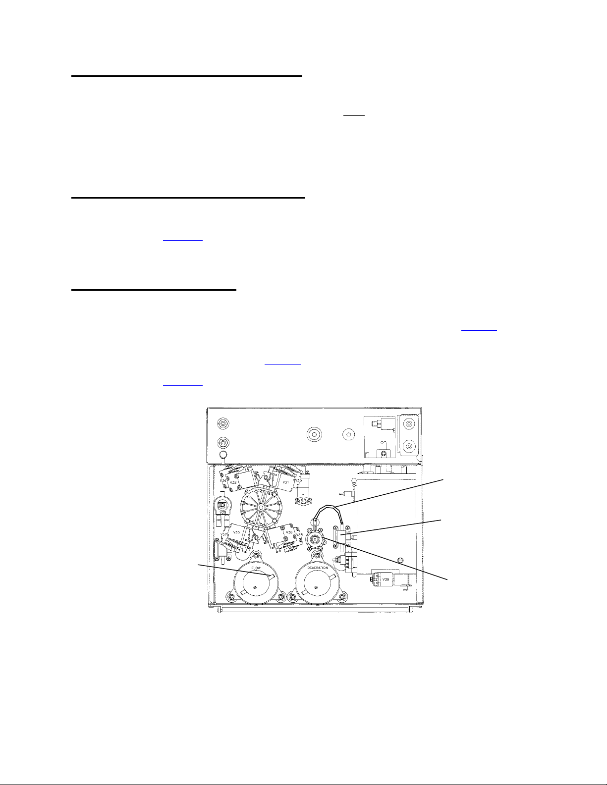
F- 21.0.0 ACFS BETWEEN 3 AND 7
The CFS transducer is not switching the balancing chamber valves properly.
Clamp the solid tubing between the output of the CFS transducer and regulator #78 (see diagram below).
Does ACFS go to below 2 now?
Yes Replace regulator #78 (see diagram below).
No See F- 21.0.1
FLOW PUMP OUTPUT
NOZZLE
REAR VIEW
CLAMP TUBING HERE
CFS TRANSDUCER
REGULATOR #78
Page 20
Fresenius 2008H Troubleshooting Guide
P/N 507082 Rev. B
Page 26

F- 21.0.1 CHECK FLOW PUMP PRESSURE
1) Remove the clamp.
2) Turn the flow off and tee a psi gauge between the flow pump's output nozzle and the SOLID tubing (see
diagram on previous page).
3) Turn the flow on at a 500 flow rate. Does pressure peak to 14 psi or greater?
Yes See F- 21.0.2
No Three possibilities: 1) Bad actuator board; 2) Bad flow pump head; 3) Bad flow pump motor.
F- 21.0.2 CHECK CFS CIRCUIT
Unplug the CFS transducer from the distribution board (position CFS) and check for bent, broken or corroded
male pins. Is ACFS between 8 and 11?
Yes See F- 21.0.3
No ACFS remains between 3 and 7. See F- 21.0.4
F- 21.0.3 CHECK SENSOR BOARD CFS VALUE
Leave the CFS transducer unplugged and call up debug screen 10. Is CFS between 8 and 11?
Yes a) Plug the CFS transducer back into distribution board (position x10, CFS).
b) If CFS remains between 3 and 7 and the flow error is still present there are four
possibilities: 1) Bad actuator board; 2) Bad flow pump head; 3) Bad flow pump motor
motor; Bad CFS transducer (see diagram, previous page).
No Replace the actuator board.
F- 21.0.4 TROUBLESHOOTING THE CFS CIRCUIT
Leave the transducer unplugged for now and call up debug screen 10. Is CFS also between 3 and 7?
Yes See F- 22.0.0
No Between 8 and 11. Replace the actuator board.
F- 22.0.0 CHECK SENSOR BOARD CABLE
a) Turn the power off and unplug the 34-pin ribbon cable from the top of the sensor board [card cage, smallest
board, right hand side].
b) Turn the power on.
c) Push the SET button ONCE to enter the VERIFY CONCENTRATE screen
d) Call up debug screen 11. Is CFS between 8 and 11 now?
Yes Unplug both sides of the 34-pin ribbon cable from the sensor and distribution board's
SENSORS connector. Look for bent male pins inside each connector. If ok replace the 34-pin
ribbon cable.
No Three possibilities: 1) Bad sensor board; 2) Bad actuator board; 3) Bad functional board;
Fresenius 2008H Troubleshooting Guide
P/N 507082 Rev. B
Page 21
Page 27

F- 23.0.0 ACFS BETWEEN 8 AND 11
An CFS transducer is acting 'open'. There are several possibilities that may cause this symptom.
Call up debug screen 10. Is CFS also reading between 8 and 11?
Yes See F- 23.0.1
No Replace the actuator board.
F- 23.0.1 CHECK CFS TRANSDUCER FOR AN 'OPEN'
a) Unplug the CFS transducer from distribution board position CFS. Check, inside the distribution board, for
bent, broken or corroded male pins.
b) Plug the 34 degree Fresenius temperature 'dummy connector' into the CFS's distribution board position
(CFS). Does CFS go to between 0 and 2?
Yes
1
Replace the CFS transducer (see diagram, page 20).
No Two possibilities: 1) 2Bad sensor board cable; 2) Bad sensor board.
1
Before replacing the transducer, check if there is a pig tail extension in the cable between the transducer
and the distribution board. If present make sure it is plugged in properly using the 'key' on the pig tail
connector. The pig tail is not present in all cases.
2
The sensor cable can be checked for continuity. Note that you are checking CFS TRANSDUCER
connections and see CHECKING THE SENSOR BOARD CABLE (page 74) .
Page 22
Fresenius 2008H Troubleshooting Guide
P/N 507082 Rev. B
Page 28

SECTION 2 - NO WATER
NW- 1.0.0 CHECK INCOMING WATER SYSTEM
a) Assure that the water is on and that the vent tube is not 'pinched' (see diagram A, page 5).
b) Turn the water off and check the input water filter for restrictions (see diagram A, page 5).
c) Before hooking the incoming water line back up assure that there is adequate incoming water flow.
d) Tee a pressure gauge at the output of side of pressure regulator #61 (see TOP VIEW diagram below) and
hook the incoming water line to the machine.
e) Turn the water on and assure that the machine is in DIALYZE mode. Pressure 19 ± 1 psi at its peak?
Yes See NW- 2.0.0
No Attempt calibration (see section 3.1, CALIBRATION MANUAL). If calibration is not possible a
bad pressure regulator #61 is indicated.
VALVE #41 (27)
PLACE GAUGE HERE
REGULATOR #61
HYDRAULICS, TOP VIEW
NW- 2.0.0 CHECK INCOMING WATER
a) Unplug the float connector from the distribution board (position x5, FLOAT-SW). Check, inside the
distribution board, for bent, broken or corroded male pins.
b) Place a jumper wire, inside the distribution board, between male pins 1 and 3 (top and middle pins). The
jumper simulates the float switch being 'closed' and should open valve #41 (27). After no more than one
minute is there overflow from the vent tube?
Yes See NW- 3.0.0
No Leave the jumper in place. A problem is indicated with VALVE 41 (27), the actuator board or
the actuator cable. NOTE this and see CHECKING VALVES (page 28).
NW- 3.0.0 CHECK FOR INTERMITTENT BAD FLOAT SWITCH
a) Loosen (but don't remove!) the screws that mount the float into the hydroblock (see HYDROBLOCK
diagram, next page). CAUTION! Don't pull the float's wiring harness.
b) Unplug the float from distribution board position FLOAT-SW. Check inside the distribution board for
corroded male pins.
Fresenius 2008H Troubleshooting Guide
Page 23
P/N 507082 Rev. B
Page 29

c) Very carefully open the cover on the female connector (see diagram below). Note that pins 2 and 5 are
missing. Clip meter leads onto pins 1 and 3 (pin 1 = top of the 100 ohm resistor, pin 3 = middle pin. See
FLOAT CONNECTOR diagram below). CAUTION! Be careful to clip onto the correct pins!
d) Move the float UP and FULLY DOWN twenty times. You should measure about 100 Ω every single time
when the float is FULLY DOWN. If the float checks good there are four possibilities:
1) Unplug both the actuator and sensor board cables from both ends and check the male connectors
and female end for corrosion;
2) Check along the length of the sensor and actuator cables for damage;
3) Check for adequate flow from the incoming water supply;
4) Check incoming water pressure (between 20 and 105 psi).
FLOAT
FLOAT SHAFT
VENT TUBE
100 OHM RESISTOR
HYDROBLOCK
PIN 1 (TOP PIN)
PIN 2 (MISSING)
PIN 3 (MIDDLE PIN)
PIN 5 (MISSING)
Page 24
Fresenius 2008H Troubleshooting Guide
P/N 507082 Rev. B
Page 30

SECTION 3 - FLOW ERRORS IN CLEANING PROGRAMS
IMPORTANT NOTE: If flow errors are occurring in HEAT DISINFECT proceed to CP- 1.0.0. If flow errors are
occurring in other CLEANING PROGRAMS proceed to CP- 2.0.0.
CP- 1.0.0 FLOW ERRORS OCCURRING SPECIFICALLY IN HEAT DISINFECT
a) Turn the power off and then back on.
b) Pull the concentrate lines out of the port and place them in concentrate. Place the machine in DIALYZE
MODE.
c) Allow temperature to become normal (about 37°C) and call up debug screen 5. Watch FLWERR for three
minutes. Does FLWERR = "1" either intermittently or constant?
Yes Return to F- 1.0.0 (page 6).
No See CP- 1.0.1
CP- 1.0.1 CHECK FOR FLOW ERRORS IN RINSE
a) Place the concentrate lines back into their ports and place the machine into RINSE.
b) Call up debug screen 5 and watch FLWERR for three minutes. Does FLWERR = "1" either intermittently or
constant?
Yes Pull the concentrate lines out of the port and place them in concentrate. Place the machine
back into DIALYZE MODE and see CP- 3.0.0 (page 26).
No See CP- 1.0.2
CP- 1.0.2 CHECKING VALVE 39
a) Pull the concentrate lines out of the port and place them in concentrate. Place the machine back into
DIALYZE MODE.
b) Check deaeration vacuum per procedure (-24 inHg to -25 inHg). Note the pressure value, leave the gauge
in line, and then place the machine into RINSE.
c) Pressure should be at least 10 inHg less than it was in dialyze mode. For example, if you were reading -24
inHg in DIALYZE mode you should read -14 inHg (or less). Is this ok?
Yes If the flow error is occurring only in HEAT DISINFECT, especially after temperature
increases, a problem may be indicated with the deaeration pump head or motor.
No Leave the machine in RINSE. A problem is indicated with VALVE 39, the actuator board or
the actuator cable. NOTE this and see CHECKING VALVES (page 28).
CP- 2.0.0 FLOW ERRORS IN RINSE, ACID CLEAN, CHEMICAL CLEAN
NOTE: If the machine will only allow RINSE use another machine's functional board. To avoid calibration
reference errors turn functional board switch #7 'on' to enter T & C mode. When troubleshooting is complete
put the original board back in.
a) Turn the power off and back on. Connect to concentrate and return to DIALYZE MODE.
b) Allow the machine to run for five minutes.
Fresenius 2008H Troubleshooting Guide
P/N 507082 Rev. B
Page 25
Page 31

c) Call up debug screen 5 and watch FLWERR for three minutes. Does FLWERR = "1" either intermittently or
constant?
Yes Return to F- 1.0.0 (page 6).
No See CP- 3.0.0
CP- 3.0.0 CHECK TMP
In the cleaning modes the dialysate pressure transducer #9 checks for flow. This procedure checks the
transducer.
From DIALYZE MODE is the TMP display pegged at either +60 or 520 mmHg?
Yes See CP- 3.0.1
No See CP- 4.0.0
CP- 3.0.1 RESET TMP
a) Push and release the RESET button on the front panel. The message "ADJUST TMP?" appears.
b) Immediately push and HOLD the RESET button. After the "ADJUSTING TMP" message is gone does TMP
remain (or return) to its pegged value?
Yes See TMP PROBLEMS (page 57).
No See CP- 4.0.0
CP- 4.0.0 CHECK VALVE 43
CAUTION During these procedures there will be spillage. Move the hydraulics away from the machine to
prevent damage.
a) Place the dialysate lines into the shunt and the concentrate connectors into their ports.
b) Clamp and remove the clear tubing from valve 43's output nozzle (see diagram below).
c) Put the machine into RINSE and call up debug screen 20. When V43= "1" the actuator board is sending a
signal to open valve 43. This occurs every two minutes for several seconds. When V43= "1" is there flow
from valve 43?
Yes Place the tubing back onto valve 43, REMOVE the clamp, and see CP- 5.0.0
No Leave the machine in RINSE. A problem is indicated with VALVE 43, the actuator board or
the actuator cable. NOTE this and see CHECKING VALVES (page 28).
Page 26
Fresenius 2008H Troubleshooting Guide
P/N 507082 Rev. B
Page 32
VALVE 43'S OUTPUT NOZZLE VALVE 29'S INPUT NOZZLE
HYDRAULICS, TOP VIEW
CP- 5.0.0 CHECK VALVE 29
a) With the machine in RINSE, clamp the clear tubing at valve 29's input nozzle as close to the valve as
possible (see diagram above) and then remove the tubing from the valve.
b) Fill a syringe with water. Using the same size tubing from valve 29 attach the syringe to valve 29's input
nozzle.
c) From debug screen 20, when V29 = "1" the actuator board is sending a signal to open valve 29. This occurs
ONLY for a few seconds every two minutes so be ready! When V29= "1" are you able to push water
through the valve with the syringe?
Yes If flow errors continue an intermittent bad dialysate pressure transducer may be indicated or a
bad deaeration pump head may be indicated.
No Leave the machine in RINSE. A problem is indicated with VALVE 29, the actuator cable or
the actuator board. NOTE this and see CHECKING VALVES (page 28).
Fresenius 2008H Troubleshooting Guide
P/N 507082 Rev. B
Page 27
Page 33
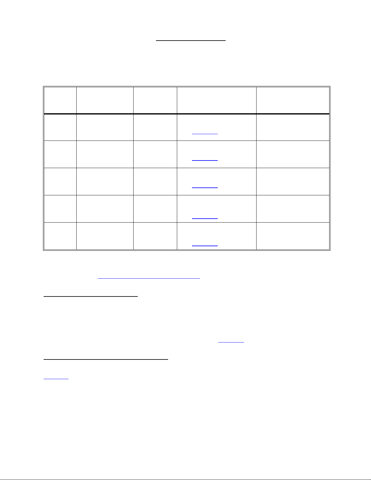
CHECKING VALVES
a) Proceed ONLY with the NOTED valve. Unplug the valve from its distribution board position (see table
below) and check for bent, broken or corroded male pins.
b) From the indicated program mode (see table below) carefully measure dc voltage, inside the distribution
board, between male pins 1 and 5 (top and bottom). Follow the instructions given.
VALVE
DISTRIBUTION
POSITION
24 V24, DIAL-V1 RINSE
41 (27) V27 DIALYSIS
39 V39, DEAR-V RINSE
29 V29, REC-V RINSE
43 V43 RINSE
1
In RINSE, voltage to valve 24 'pulses' on and off from between 26 to 22 vdc (on) to less than 2 vdc.
2
The actuator cable can be checked for continuity. NOTE the specific VALVE whose connection you are
PROGRAM
MODE
GOOD
1
Pulsing on and off,
see CV- 1.0.0
22 to 26 vdc,
see CV- 1.0.0
22 to 26 vdc,
see CV- 1.0.0
22 to 26 vdc ONLY when
debug screen 20, V29 = 1,
see CV- 1.0.0
22 to 26 vdc ONLY when
debug screen 20, V43 = 1,
see CV- 1.0.0
BAD = LESS THAN
20 VDC
Two possibilities:
2
1)
Bad actuator cable
2) Bad actuator board
Two possibilities:
2
1)
Bad actuator cable
2) Bad actuator board
Two possibilities:
2
1)
Bad actuator cable
2) Bad actuator board
Two possibilities:
2
1)
Bad actuator cable
2) Bad actuator board
Two possibilities:
2
1)
Bad actuator cable
2) Bad actuator board
checking and see CHECKING THE ACTUATOR CABLE (page 72).
CV- 1.0.0 CHECK FOR AN OPEN
Open the plastic cover of the female distribution board connector. Leaving it unplugged measure resistance
between pins 1 and 5 (wires connected) inside the female connector. 50 to 80 Ω?
Yes The valve is bad or possibly restricted.
No Leave the connector unplugged for now and see CV- 1.0.1
CV- 1.0.1 CHECK SOLENOID RESISTANCE
A two-wire harness runs from the female connector and plugs onto two terminals at the valve's solenoid. See
diagrams (page 32) to locate valves. Leaving the female connector unplugged measure resistance between
the male solenoid terminals. 50 to 80 Ω ?
Yes The harness between the distribution board and the solenoid is bad.
No Replace the valve.
Page 28
Fresenius 2008H Troubleshooting Guide
P/N 507082 Rev. B
Page 34
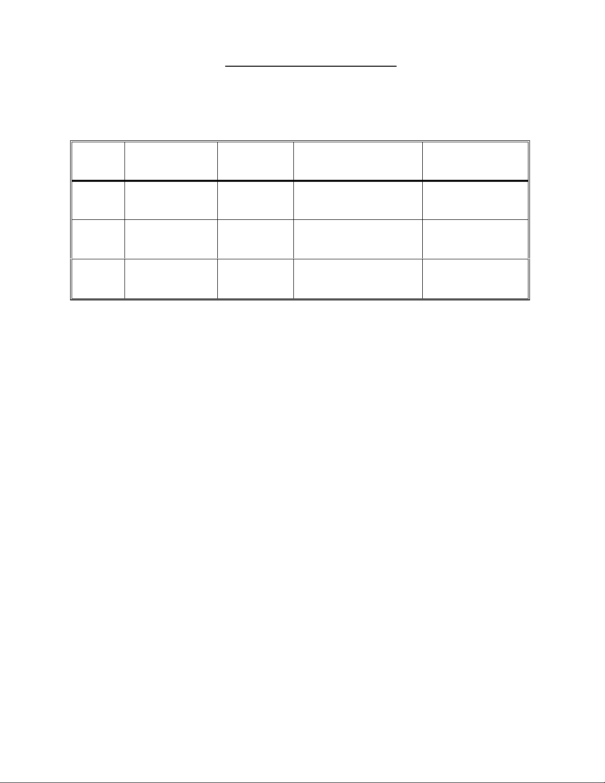
TROUBLESHOOTING VALVES
a) Proceed ONLY with the NOTED valve. Unplug the valve at the distribution board (see table below) and
check for bent, broken or corroded male pins.
b) From the indicated program mode (see table below) measure voltage, inside the distribution board,
between male pins 1 and 5 (top and bottom). Follow the instructions given.
VALVE
DISTRIBUTION
POSITION
25 V25, DIAL-V2
26 V26, BYPASS-V RINSE
30 V30, DRAIN-V DIALYZE
1
In RINSE, voltage to valve 26 'pulses' on and off from between 26 to 22 vdc (on) to less than 2 vdc.
PROGRAM
MODE
SELECT ANY
PROGRAM
GOOD BAD
22 to 26 vdc, valve 25 is
bad or possibly restricted
1
Pulsing on and off, valve
26 is bad or possibly
restricted
22 to 26 vdc, valve 30 is
bad or possibly restricted
Less than 20 vdc,
Bad actuator board
Less than 20 vdc,
Bad actuator board
Less than 20 vdc,
Bad actuator board
Fresenius 2008H Troubleshooting Guide
P/N 507082 Rev. B
Page 29
Page 35
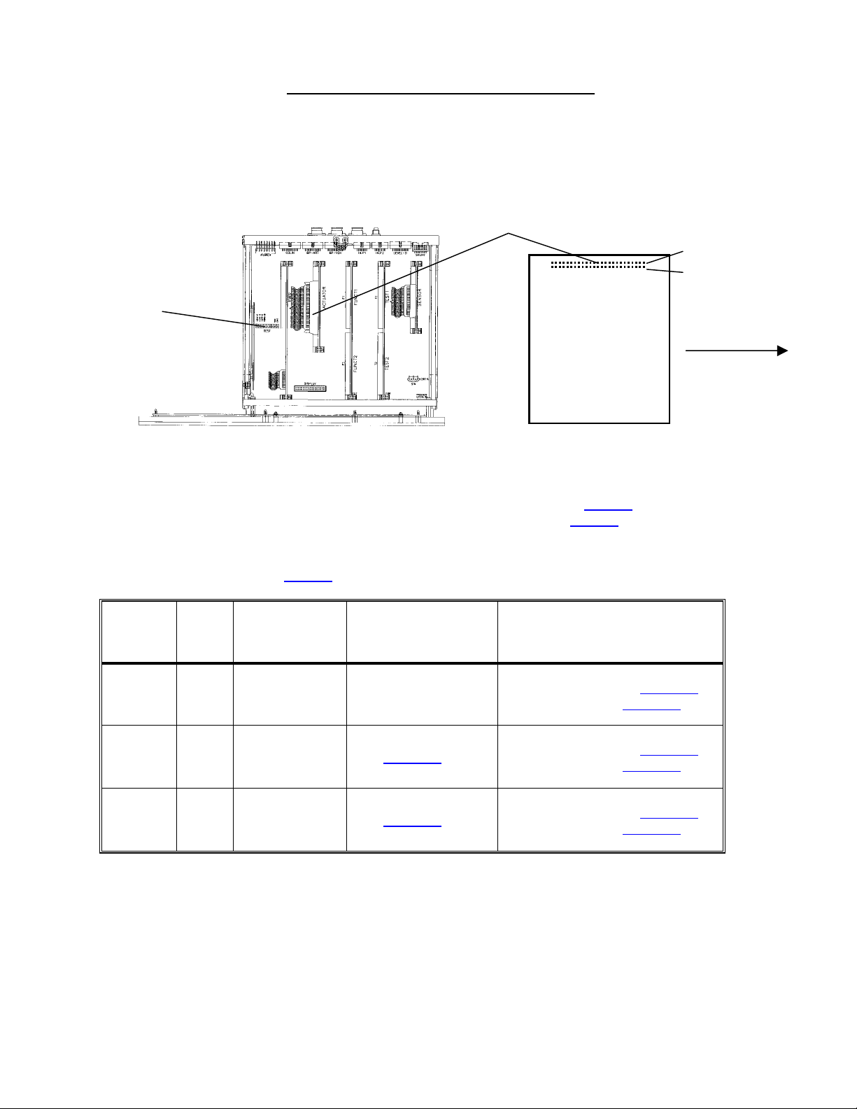
TROUBLESHOOTING VALVE ERRORS
Proceed ONLY with the NOTED valve(s).
a) Turn the power off and clip a ground lead onto PGND-B at the TEST connector (see diagram, below).
b) At the top of the actuator board (see diagram below) there is a large 50-pin connector called the 'P2'. A
ribbon cable plugs in here that runs to the distribution board.
P2 CONNECTOR
PIN 2 (TOP)
PIN 1 (BOTTOM)
TEST CONNECTOR
(FOR GROUND)
ACTUATOR BOARD
(SOLDER SIDE)
REAR OF MACHINE
CARD CAGE
c) Measure resistance at the solder (back) side pins of the P2 connector as directed in the table. See
TABLE 1 to check VALVES 30, 26 and 25 (as prompted from steps 1 or 3, F- 5.0.1). See TABLE 2 to
check the BALANCING CHAMBER VALVES (as prompted from step 2, F- 5.0.1). Follow directions given:
TABLE 1 (from step 1 or 3, F- 5.0.1) TO CHECK VALVES 30, 26 AND 25
BAD = LESS THAN 50 OR
GREATER THAN 80 Ω
(NOTE M Ω = MEG OHMS)
Greater than 80, See VE- 1.0.0
Less than 50, See VE- 1.0.4
Greater than 80, See VE- 1.0.0
Less than 50, See VE- 1.0.4
Greater than 80, See VE- 1.0.0
Less than 50, See VE- 1.0.4
VALVE PIN
30 35
26 31
25 30
P2 PIN
LOCATION
bottom row, 8
pins from front
bottom row, 10
pins from front
top row, 11
pins from front
GOOD = BETWEEN
50 AND 80 Ω
Check also valve 26
See VE- 1.0.2
See VE- 1.0.2
Page 30
Fresenius 2008H Troubleshooting Guide
P/N 507082 Rev. B
Page 36
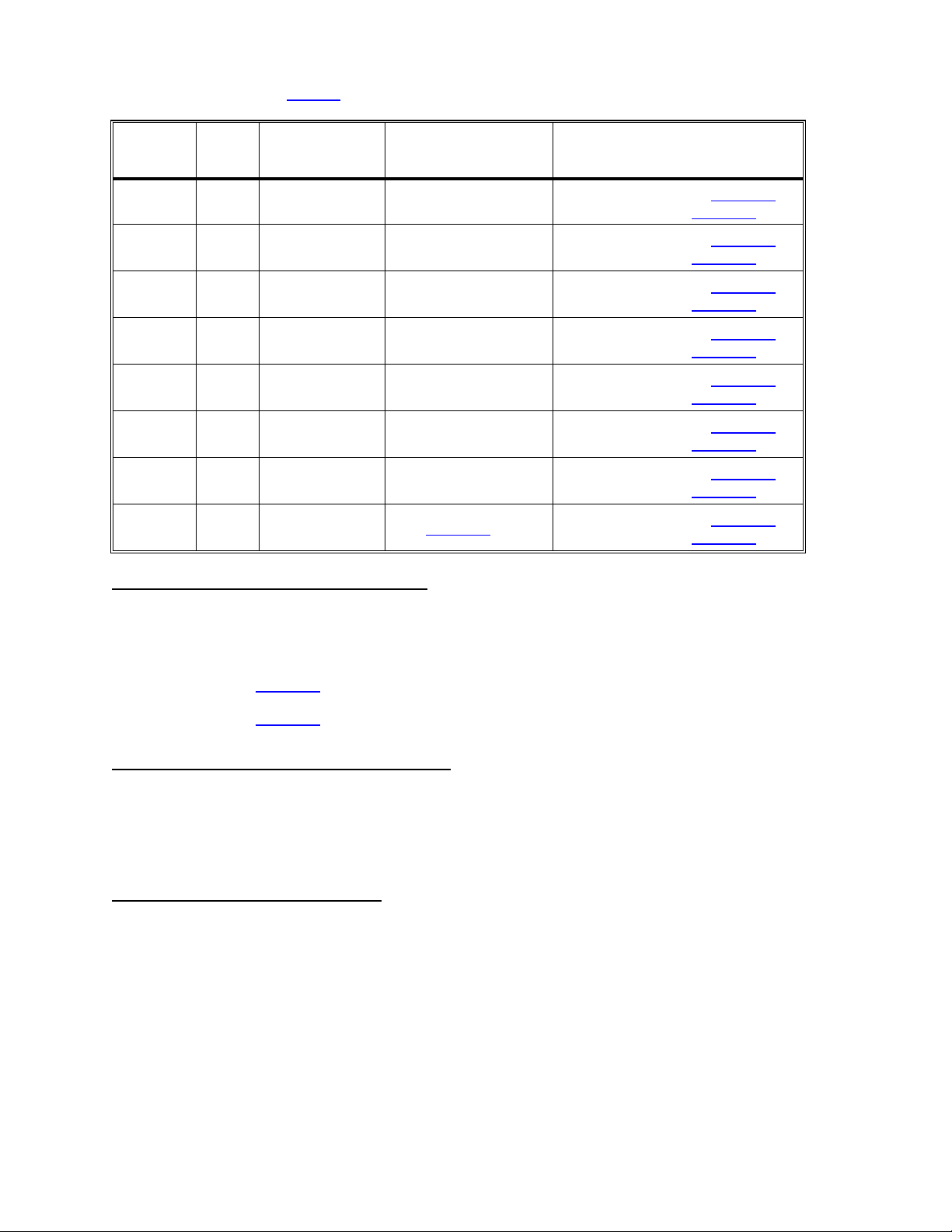
TABLE 2 (from step 2, F- 5.0.1) TO CHECK BALANCING CHAMBER VALVES
VALVE PIN
31 36
32 37
33 38
34 39
35 40
36 41
37 42
38 43
VE- 1.0.0 CHECK FOR AN 'OPEN' CIRCUIT
P2 PIN
LOCATION
top row, 8 pins
from front
bottom row, 7
pins from front
top row, 7 pins
from front
bottom row, 6
pins from front
top row, 6 pins
from front
bottom row, 5
pins from front
top row, 5 pins
from front
bottom row, 4
pins from front
GOOD = BETWEEN
50 AND 80 Ω
Check also valve 32
Check also valve 33
Check also valve 34
Check also valve 35
Check also valve 36
Check also valve 37
Check also valve 38
See VE- 1.0.2
BAD = LESS THAN 50 OR
GREATER THAN 80 Ω
(NOTE M Ω = MEG OHMS)
Greater than 80, See VE- 1.0.0
Less than 50, See VE- 1.0.4
Greater than 80, See VE- 1.0.0
Less than 50, See VE- 1.0.4
Greater than 80, See VE- 1.0.0
Less than 50, See VE- 1.0.4
Greater than 80, See VE- 1.0.0
Less than 50, See VE- 1.0.4
Greater than 80, See VE- 1.0.0
Less than 50, See VE- 1.0.4
Greater than 80, See VE- 1.0.0
Less than 50, See VE- 1.0.4
Greater than 80, See VE- 1.0.0
Less than 50, See VE- 1.0.4
Greater than 80, See VE- 1.0.0
Less than 50, See VE- 1.0.4
Unplug the NOTED valve from the distribution board (for example, valve 36 plugs into position V36) and open
the plastic cover from the female connector. Leaving the female connector unplugged measure between pins
1 and 5 (where the wires are soldered) inside the female connector. Between 50 and 80 Ω?
Yes See VE- 1.0.4
No See VE- 1.0.3
VE- 1.0.2 CHECK ACTUATOR BOARD CABLE
Unplug the actuator board cable from both ends (the cable terminates at distribution board's ACTUATOR
connector): a) Using a flashlight check the male side of each connector for (white) corrosion. Check also for
bent or broken pins; b) Check the female side of both connectors for (white) corrosion. If ok replace the
actuator cable.
VE- 1.0.3 CHECK VALVE SOLENOID
Each valve has a two-pin wiring harness that runs from the distribution board and terminates at its solenoid
where it plugs onto *two male terminals (see the diagrams (next page) to locate the NOTED valve). Unplug
the harness and measure between the male solenoid terminals. Between 50 and 80 Ω?
Yes The wiring harness is bad.
No Replace the valve.
* Some harnesses may wire directly into the solenoid. If so replace the valve.
Fresenius 2008H Troubleshooting Guide
P/N 507082 Rev. B
Page 31
Page 37
VE- 1.0.4 CHECK ACTUATOR BOARD CABLE
Unplug the actuator cable from the distribution board (ACTUATOR connector). Leave the actuator board side
plugged in. Measure again at the NOTED valve's actuator board P2 connector pin (as instructed above).
Greater than 2 MΩ now?
Yes See VE- 1.0.5
No Unplug the actuator cable from the actuator board itself and measure again at the NOTED
valve's actuator board P2 connector pin (as instructed above). If less than 2 MΩ replace the
actuator board (shorted driver) otherwise proceed to VE- 1.0.5
VE- 1.0.5 CHECK ACTUATOR CONNECTOR PINS/ VALVE HARNESS
a) Using a flashlight check for bent or (white) corroded male pins at each connector (both at the actuator board
and distribution board side).
b) Check the 2-pin wiring harness that runs from the NOTED valve's solenoid to the distribution board. If
damage is seen replace the harness.
c) Plug all cables back in and place the machine back into dialyze mode. If the VALVE ERROR continues
there are two possibilities: 1) Bad actuator board; 2) Bad actuator cable.
VALVE 34
(BEHIND VALVE 32)
VALVE 32
VALVE 37
(BEHIND VALVE 35)
VALVE 35
VALVE 26
VALVE 24
VALVE 33
(BEHIND VALVE 31)
VALVE 31
VALVE 38
(BEHIND VALVE 36)
VALVE 36
VALVE 39
HYDRAULICS, REAR VIEW
VALVE 43 VALVE 29 VALVE 41 (27)
VALVE 30
HYDRAULICS,
TOP VIEW
Page 32
Fresenius 2008H Troubleshooting Guide
P/N 507082 Rev. B
Page 38

SECTION 4 - TEMPERATURE PROBLEMS
CAREFULLY read the list of symptoms and proceed with the one that best describes the problem:
1. TEMP display remains at 33°C; a) Check that the heater breaker switch is on i.e "1" is pushed in (see
diagram A, page 5); b) If the problem is still present after 10 minutes see T- 1.0.0
2. TEMP display increases to about 40°C, falls and then rises again. See T- 4.0.0
3. You are currently attempting HEATER CONTROL CALIBRATION but it does not calibrate properly: a)
Check that the heater breaker switch is on i.e."1" is pushed in (see diagram A, page 5); b) If 'measured'
temperature increases to 40°C (or greater) causing no flow through the external flow indicator RETURN to
DIALYZE mode and see T- 4.0.0; c) If parts a and b do not describe the problem RETURN to DIALYZE
mode and see T- 1.0.0.
4. The machine is currently in HEAT DISINFECT and:
• TEMPERATURE remains at 33°C; a) Check that the heater breaker switch is on i.e."1" is
pushed in (see diagram A, page 5); b) If the problem is still present after 10 minutes RETURN to
DIALYZE mode and see T- 1.0.0
• TEMPERATURE fails to reach 80°C but is greater than 33°C. See T- 3.0.0
• TEMPERATURE increases to about 90°C, falls and then rises again. See T- 4.0.0
5. TEMP display and measured 'actual' temperature are not the same. Watch VERY carefully for 10 minutes
to assure that the TEMP display is remaining stable. If so see T- 5.0.0
T- 1.0.0 CHECK FOR NO WATER, FLOW ERROR AND FILLING PROGRAM
a) Call up debug screen 5 and carefully watch !WATER and FLWERR for two minutes. If either goes to "1"
(intermittently or constant) see FLOW ERRORS IN DIALYZE MODE (page 6).
b) Call up debug screen 7. If FILACT = "1" a FILLING PROGRAM is present. Do NOT troubleshoot
TEMPERATURE PROBLEMS with a FILLING PROGRAM present. If FILACT = "0" proceed to T- 1.0.1
T- 1.0.1 CHECK TEMP SET POINT
From the main DIALYSIS screen use the arrow keypads to select TEMP and push the SET keypad to make a
"?" appear. The indicated TEMP value is the current 'set point'. If necessary use the arrows keypads to adjust
'set point' and push the SET keypad again. Allow 10 minutes for stabilization. If adjustment is not necessary
or if the problem is still present see T- 1.0.2.
T- 1.0.2 CHECK HEATER VOLTAGE
CAUTION 120 VAC!. Measure ac voltage, between the BLUE and BROWN heater wires at the distribution
board's heater connector (see diagram, next page). Voltage may be 'pulsing' causing the meter to O.L.
intermittently (this is normal). Greater than 90 vac?
Yes See T- 1.0.3
No See T- 2.0.0
Fresenius 2008H Troubleshooting Guide
P/N 507082 Rev. B
Page 33
Page 39

HEATER CONNECTOR
NTC-2
NTC-3
BLUE WIRE BROWN WIRE
T- 1.0.3 CHECK HEATER
IMPORTANT turn the POWER OFF. Measure RESISTANCE between the BLUE and BROWN heater wires
(see diagram above). Between 10 and 13 Ω?
Yes See T- 5.0.0 (page 43).
No Replace the heater.
T- 2.0.0 CHECK LOGIC SIGNALS
CAUTION During these procedures dc voltages are measured at the solder (back) side of the POWER
LOGIC BOARD'S x2 connector. The pins are very close to each other and 'shorting' them together with a
meter probe can damage the board. It is RECOMMENDED that you use TP80 (non-standard) meter probes
together with the slip-on cap.
a) Turn the power off and clip a ground lead onto SGND at the TEST connector (see diagram below).
b) At the top, very front of the POWER LOGIC BOARD is the 20-pin 'x2' connector (see diagram below). A
ribbon cable terminates here that runs into the upper power supply. The solder side pins are arranged in
two rows. Top are the even numbered, bottom are odd.
c) Turn the power on and go to DIALYZE MODE by pushing the SET twice button. Measure at the pins
specified in the LOGIC SIGNALS table (next page) and follow the directions given:
POWER LOGIC
BOARD
TEST CONNECTOR
(FOR GROUND)
x2 CONNECTOR
Page 34
CARD CAGE
Fresenius 2008H Troubleshooting Guide
P/N 507082 Rev. B
PIN 6 PIN 2
PIN 7
POWER LOGIC BOARD
(SOLDER SIDE)
x2 CONNECTOR
REAR OF
MACHINE
Page 40
LOGIC SIGNALS
PIN x2 LOCATION GOOD SIGNAL (vdc) BAD SIGNAL (vdc)
6
7
2
top row, three pins from
the rear
bottom row, four pins
from the rear
top row, first pin from
the rear
9.6 or greater, measure at
x2, pin 7
4 or greater, measure at x2,
pin 2
3.6 or lower, see T- 2.1.0
1.5 or lower, see T- 2.2.0
2 or lower, see T- 2.4.0 22 to 26, see T- 2.3.0
T- 2.1.0 CHECK SENSOR BOARD SIGNAL
a) At the very BOTTOM, left hand side (component side) of the SENSOR board is its motherboard connector
(see CARD CAGE diagram below). A row of pins extend horizontally, turns 90 degrees downward and runs
into the connector. This is the "C row", numbered 1 through 32 (from front-to-rear).
SENSOR BOARD
FRONT OF MACHINE
PIN C1
CARD CAGE
MOTHER BOARD
CONNECTOR
b) Using a STANDARD meter probe (do NOT use the non-standard probe) CAREFULLY measure voltage at
pin C1 (very FRONT motherboard pin). High (9.6 vdc or greater) or low (less than 3.6 vdc)?
High See T- 2.1.2
Low See T- 2.1.1
T- 2.1.1 CHECK POWER LOGIC BOARD
a) Turn the power off and swap in a power logic board.
b) Turn the power on and measure again at the power logic board's x2 connector, pin 6. High (9.6 vdc or
greater) or low (3.6 vdc of lower)?
High The previous power logic board is bad.
Low See T- 2.5.0 (the previous power logic board is good).
T- 2.1.2 CHECK NTC-2
Unplug NTC-2 from the distribution board (FIRST! position on left, x2 CON-NTC). Does pin C1 go low?
Yes Replace NTC-2.
No See T- 2.1.3
Fresenius 2008H Troubleshooting Guide
P/N 507082 Rev. B
Page 35
Page 41

T- 2.1.3 CHECK NTC-2 CIRCUIT
a) Turn the power off and unplug both ends of the 34-pin sensor board cable. Check for bent, broken or
corroded male pins at each connector.
b) Plug the cable back in and swap a power logic board.
c) Turn the power back on and measure again at the sensor board's motherboard pin C1. High (9.6 vdc or
greater) or low (3.6 vdc or lower)?
High Replace the sensor board (the previous power logic board is good).
Low The previous power logic board is bad
T- 2.2.0 CHECK FOR FLOW ERRORS
Call up debug screen 5. Is FLWERR = "1"?
Yes See FLOW ERRORS IN DIALYZE MODE (page 6).
No See T- 2.2.1
T- 2.2.1 CHECK ACTUATOR BOARD
a) Turn the power off and swap in an actuator board.
b) Turn the power on and go to DIALYZE MODE by pushing the SET button twice.
c) Measure again at the power logic board's x2 connector, pin 7. High (greater than 4 vdc) or low (less than
1.5 vdc)?
High The previous actuator board is bad.
Low See T- 2.5.0 (the previous actuator board is good).
T- 2.3.0 CHECK POWER LOGIC/FUNCTIONAL BOARD
a) Turn the power off and swap in a power logic board.
b) Turn the power on and go to DIALYZE MODE by pushing the SET button twice. Wait 15 seconds.
c) Measure again at the solder side of the power logic board's x2 connector, pin 2 (top row, first pin from rear).
Less than 2 vdc now?
Yes The previous power logic board was bad.
No Replace the functional board (the previous power logic board is good).
T- 2.4.0 CHECK HEATER RELAY
a) Turn the power off and then back on. Allow the SELECT PROGRAM screen to come up. IMPORTANT! Do
NOT enter dialyze mode.
b) From SELECT PROGRAM measure again at the solder side of the power logic board's x2 connector, pin 2
(top row, first pin from rear). Approximately 24 ± 2.0 vdc?
Page 36
Yes See T- 2.6.0
No See T- 2.5.0
Fresenius 2008H Troubleshooting Guide
P/N 507082 Rev. B
Page 42

T- 2.5.0 CHECK POWER LOGIC CABLE/POWER CONTROL BOARD
Either the 20-pin power logic board cable or the power control board is bad.
a) Turn the power off and UNPLUG the machine. CAUTION, 120 VAC IF NOT UNPLUGGED!
b) Slide the upper power supply (see diagram A, page 5) away from the cabinet. Inside is the power control
board where the 20-pin 'x2' cable terminates. Check that the cable is plugged in properly.
c) Unmount the power control board from the plastic clips to allow easy access to the rear (solder) side (see
diagram below).
d) Measure resistance from pin 2, at the POWER LOGIC BOARD'S end of the cable (x2 connector, top row,
first pin from rear), to pin 2 at the POWER CONTROL BOARD'S end. If the cable is good (10 Ω or less)
replace the POWER CONTROL BOARD.
PIN 2 PIN 7
x2 CONNECTOR
PIN 6
POWER CONTROL BOARD
REAR (SOLDER) SIDE
K1
K2
ST 9
ST 8 ST 11
ST 5
ST 13
ST 4
ST 7
T- 2.6.0 CHECK POWER LOGIC BOARD CABLE
a) Turn the power off and UNPLUG the machine. CAUTION, 120 VAC IF NOT UNPLUGGED!
b) Slide the upper power supply (see diagram A, page 5) away from the cabinet. Inside is the power control
board where the 20-pin 'x2' cable terminates. Check that the cable is plugged in properly.
c) Unmount the power control board from the plastic clips to allow easy access to the rear (solder) side (see
diagram above). Measure resistance from (two measurements):
1) Pin 6, at the POWER LOGIC BOARD'S end of the cable (x2 connector, top row, three pins
from rear), to pin 6 at the POWER CONTROL BOARD'S end (see diagram above).
2) Pin 7, at the POWER LOGIC BOARD'S end of the cable (x2 connector, bottom row, four pins
from rear), to pin 7 at the POWER CONTROL BOARD'S end (see diagram above).
d) If the cable is good (10Ω or less) see T- 2.6.1
Fresenius 2008H Troubleshooting Guide
P/N 507082 Rev. B
Page 37
Page 43

T- 2.6.1 CHECK TRIAC VOLTAGE DROP
a) Set meter to ac volts and CLIP the leads, onto the SOLDER side of the power control board, at connectors
ST 8 and ST 11 (see diagram, previous page).
b) Plug the machine in. CAUTION, 120 VAC NOW PRESENT!
c) Turn the power on and go to DIALYZE MODE by pushing the SET button twice. Wait 15 seconds. Greater
than 90 vac across the triac?
Yes See T- 2.6.2
No See T- 2.7.0
T- 2.6.2 CHECK TRIAC GATE SIGNAL
a) Turn the POWER OFF and UNPLUG the machine.
b) CLIP the meter leads, onto the SOLDER side of the power control board at connector K 2 and terminal ST9
(see diagram, previous page).
c) Plug the machine in. CAUTION, 120 VAC NOW PRESENT!
d) Turn the power on and go to DIALYZE MODE by pushing the SET button twice. Wait 15 seconds. 90 vac or
greater?
Yes Bad power control board.
No Bad triac (trace the orange wire from connector ST 9 down to the triac).
T- 2.7.0 CHECK HEATER CONNECTIONS
a) Turn the POWER OFF and UNPLUG the machine.
b) Measure resistance, on the SOLDER side of the power control board, between connectors K 2 and K 1
(see diagram, previous page). Less than 20 Ω (ohms)?
Yes See T- 2.7.1
No Check for an 'open' circuit to the heater.
T- 2.7.1 CHECK HEATER BREAKER
a) Referring to the diagram on the previous page measure resistance, on the SOLDER side of the power
control board, BETWEEN connectors:
1) ST 7 and ST 13
2) ST 4 and ST 5
b) Both less than 30 ohms?
Yes See T- 2.7.2
No Replace the heater breaker. It is 'open'.
Page 38
Fresenius 2008H Troubleshooting Guide
P/N 507082 Rev. B
Page 44

T- 2.7.2 CHECK HEATER VOLTAGE
a) Turn the power on and go to DIALYZE MODE by pushing the SET button twice.
b) CAUTION 120 VAC!. Measure ac voltage, between the GREEN and BROWN heater wires at the
distribution board's heater connector (see diagram below). Greater than 90 vac?
Yes Everything is checking good. If the temperature problem is still present return to T- 1.0.0 and
proceed carefully.
No Replace the power control board (inside upper power supply).
HEATER CONNECTOR
NTC-2 NTC-3
GREEN WIRE
BLUE WIRE
BROWN WIRE
T- 3.0.0 CHECK HEATER
a) Turn the heater breaker switch off (see diagram A, page 5) and allow the TEMP display to reach 33°C.
b) Turn the POWER OFF and measure RESISTANCE, between the BROWN and BLUE heater wires at the
distribution board's heater connector (see diagram above). Between 10 and 13 Ω?
Yes Turn the heater breaker switch back on and see T- 3.0.1
No Replace the heater
T- 3.0.1 CHECK TEMPERATURE DISPLAY
a) Place the machine in DIALYZE MODE (this procedure does not work in HEAT DISINFECT).
b) Plug the 40°C Fresenius temperature 'dummy' connector into NTC-3's distribution board position (MON-
NTC, SECOND! position from the left). CAUTION! Be careful to plug into the correct position.
c) Does the TEMP display (main screen) read between 38 and 42°C?
Yes See T- 3.0.2
No See T- 6.0.0 (page 43).
Fresenius 2008H Troubleshooting Guide
P/N 507082 Rev. B
Page 39
Page 45

T- 3.0.2 CHECK RECIRCULATION
Return to HEAT DISINFECT and call up debug screen 20. When V29 = "1" the actuator board is opening
recirc valve 29. Wait until V29 = "1" CONSTANTLY. Is there flow to the drain?
Yes See T- 3.0.3
No Note that NTC-2 OR NTC-3 may be a problem and see T- 9.0.0 (page 44).
T- 3.0.3 CHECK VALVE 30
Unplug valve 30 from the distribution board (position V30). Does flow to the drain stop?
Yes Replace the actuator board.
No Replace valve 30.
T- 4.0.0 CHECK SENSOR BOARD SIGNAL
a) Turn the power off and clip a ground lead onto SGND at the TEST connector (see diagram below).
NOTE: Troubleshooting this symptom CANNOT be done in HEAT DISINFECT. If currently in HEAT
DISINFECT return to DIALYZE MODE.
b) Plug the 80°C Fresenius test (temperature) 'dummy connector' into NTC-2's distribution board position
(FIRST! position on the left, CON-NTC). CAUTION! Be careful to plug in correctly!
c) At the very BOTTOM, left hand side (component side), of the SENSOR board is its motherboard connector
(see CARD CAGE diagram below). A row of pins extend horizontally, turns 90 degrees downward, and runs
into the connector. This is the "C row", numbered 1 through 32 (from front-to-rear).
d) Turn the power on. Using a STANDARD meter probe (do not use the non-standard probe) CAREFULLY
measure dc voltage at pin C1 (very FRONT motherboard pin). High (9.6 vdc or greater) or low (less than
3.6 vdc)?
High Leave the 'dummy' in for now and see T- 4.1.0
Low Note that NTC-2 may be a problem and see T- 9.0.0 (page 44).
SENSOR BOARD
FRONT OF MACHINE
PIN C1
Page 40
CARD CAGE
Fresenius 2008H Troubleshooting Guide
MOTHER BOARD
CONNECTOR
P/N 507082 Rev. B
Page 46

T- 4.1.0 CHECK LOGIC SIGNAL
CAUTION During these procedures dc voltages are measured at the solder (back) side of the POWER
LOGIC BOARD'S x2 connector. The pins are very close to each other and 'shorting' them together with a
meter probe can damage the board. It is RECOMMENDED that you use TP80 (non-standard) meter probes
together with the slip-on cap.
a) At the top, very front of the POWER LOGIC BOARD is the 20-pin 'x2' connector (see diagram below). A
ribbon cable terminates here that runs into the upper power supply. The solder side pins are arranged in
two rows. Top are the even numbered, bottom are odd.
PIN 6 PIN 2
POWER LOGIC
BOARD
x2 CONNECTOR
TEST CONNECTOR
(FOR GROUND)
x2 CONNECTOR
POWER LOGIC BOARD
(SOLDER SIDE)
REAR OF
MACHINE
CARD CAGE
b) Turn the power on and measure at the solder side of the x2 connector, pin 6 (top row, 3 pins from rear).
High (greater than 9.6 vdc) or low (less than 3.6 vdc)?
High See T- 4.2.0
Low Watch the TEMP display (main screen) for 8 minutes (as necessary). Drop to 33°C?
Yes Replace NTC- 2
No Continues to increase to about 40°C (or greater), see T- 4.3.0.
T- 4.2.0 CHECK POWER LOGIC BOARD
a) Turn the power off and swap the power logic board.
b) Turn the power back on and go to DIALYZE MODE. Watch for 10 minutes. If TEMP continues to increase to
about 40°C replace the power control board (inside the upper power supply). The previous power logic
board is good.
T- 4.3.0 CHECK FOR A SHORTED TRIAC
a) Turn the power off and UNPLUG the machine. CAUTION, 120 VAC IF NOT UNPLUGGED!
b) Unmount the upper power supply from the cabinet (see diagram A, page 5). Inside is the power control
board which is mounted to the case with plastic clips. Unmount the board from the clips to allow easier
access to the back (solder) side of the board.
c) Measure resistance, on the solder side of the power control board, between connectors ST 8 and ST 11
(see SOLDER SIDE diagram, next page). Greater than 3 Meg Ω?
Yes See T- 4.4.0
No Replace the triac (trace the blue, brown and orange wires to it).
Fresenius 2008H Troubleshooting Guide
Page 41
P/N 507082 Rev. B
Page 47

POWER CONTROL BOARD
SO
LDER SIDE
POWER CONTROL BOARD
FRONT SIDE
ST 8 ST11 ST 9 (GATE)
T- 4.4.0 CHECK TEMP CALIBRATION
a) Turn the power off and place the machine in SERVICE/CALIBRATION. Connect a temperature meter into
the dialysate lines to measure 'actual' temperature. CAUTION Fluid may be hot!
b) Turn the power back on and enter HEAT TEMP CONTROL. Lower the DAC value to "0".
c) Watch 'actual' temperature for 8 minutes. Continue to increase to high?
Yes Leave the temperature meter in line for now and see T- 4.5.0
No Plug NTC-2 back into the distribution board (FIRST! position on the left, CON-NTC) and
calibrate HEATER TEMP CONTROL.
T- 4.5.0 REMOVE TRIAC'S GATE SIGNAL
a) Turn the power off and UNPLUG the machine. CAUTION, 120 VAC IF NOT UNPLUGGED!
b) Unplug the female terminal connector from the power control board's (GATE) terminal ST 9 (see FRONT
SIDE diagram above).
c) Wrap BLACK tape around the female terminal connector. CAUTION! The connector is 'live' (120 vac) when
the power is on. Damage to the machine or electrocution may occur if not wrapped.
d) Plug the machine in (CAUTION, 120 VAC NOW PRESENT!). Turn the power on and enter
CALIBRATION/HEAT TEMP CONTROL.
e) Lower the DAC value to "0" and watch 'actual' temperature for 8 minutes. Continue to increase to high?
Yes Replace the triac and calibrate HEATER TEMP CONTROL.
No Replace the power control board and calibrate HEATER TEMP CONTROL.
Page 42
Fresenius 2008H Troubleshooting Guide
P/N 507082 Rev. B
Page 48
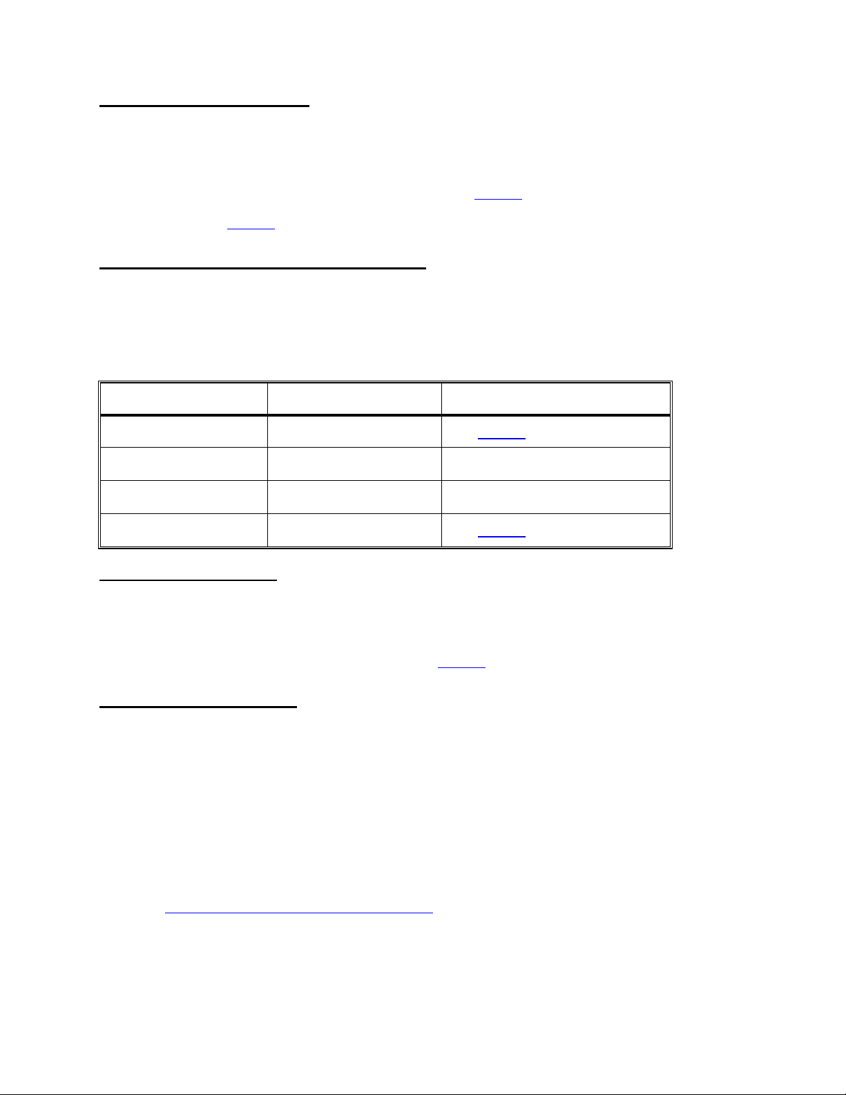
T- 5.0.0 CHECK TEMP DISPLAY
Plug the 40°C Fresenius test (temperature) 'dummy connector' into NTC-3's position (SECOND! position from
the left, MON-NTC). CAUTION! Plug in correctly. Does the TEMP display (main screen) read between 38 and
42°C?
Yes Note that NTC- 3 may be a problem and see T- 9.0.0 (page 44).
No See T- 6.0.0
T- 6.0.0 CHECK DEBUG TEMPERATURE VALUES
a) With the 41°C (5.11KΩ) connector plugged in call up debug screen 9 and note TEMP. Good = 8.5 (+/- 1.6)
vdc.
b) Call up debug 11 and note ATEM. Good = 7.7 (+/- 0.3) vdc. Refer to DEBUG table below.
DEBUG TABLE
DEBUG 9, TEMP DEBUG 11, ATEM RESPONSE
GOOD GOOD See T- 7.0.0
GOOD BAD Replace the actuator board
BAD GOOD Replace the sensor board
BAD BAD See T- 8.0.0
T- 7.0.0 CALIBRATE TEMP
a) Plug NTC-3 back into distribution board (SECOND! position from left, x3 MON-NTC). CAUTION! Be sure to
plug in correctly.
b) Calibrate HEATER CONTROL per CALIBRATION PROCEDURES, section 2.5. If not successful note that
either NTC- 2 or NTC- 3 may be a problem and see T- 9.0.0 (page 44).
T- 8.0.0 CHECK TEST BOARD
a) Turn the machine off and swap in a test board. NOTE: An alternative is to remove IC 4 from the test board.
The machine runs ok but will not pass tests.
b) Turn the power on and enter dialyze mode. With the 41°C (5.11KΩ) dummy connector plugged in call up
debug screen 9. TEMP = 8.5 (+/- 1.6) vdc?
Yes The previous test board (or IC 4, test board) is bad.
No Four possibilities: 1) *Bad sensor board cable; 2) HEAT TEMP CONTROL not calibrated
accurately; 3) Bad sensor board; 4) Bad functional board.
* The sensor cable can be checked for continuity. Note that you are checking NTC-2 and NTC-3 connections
and see CHECKING THE SENSOR BOARD CABLE (page 74).
Fresenius 2008H Troubleshooting Guide
P/N 507082 Rev. B
Page 43
Page 49
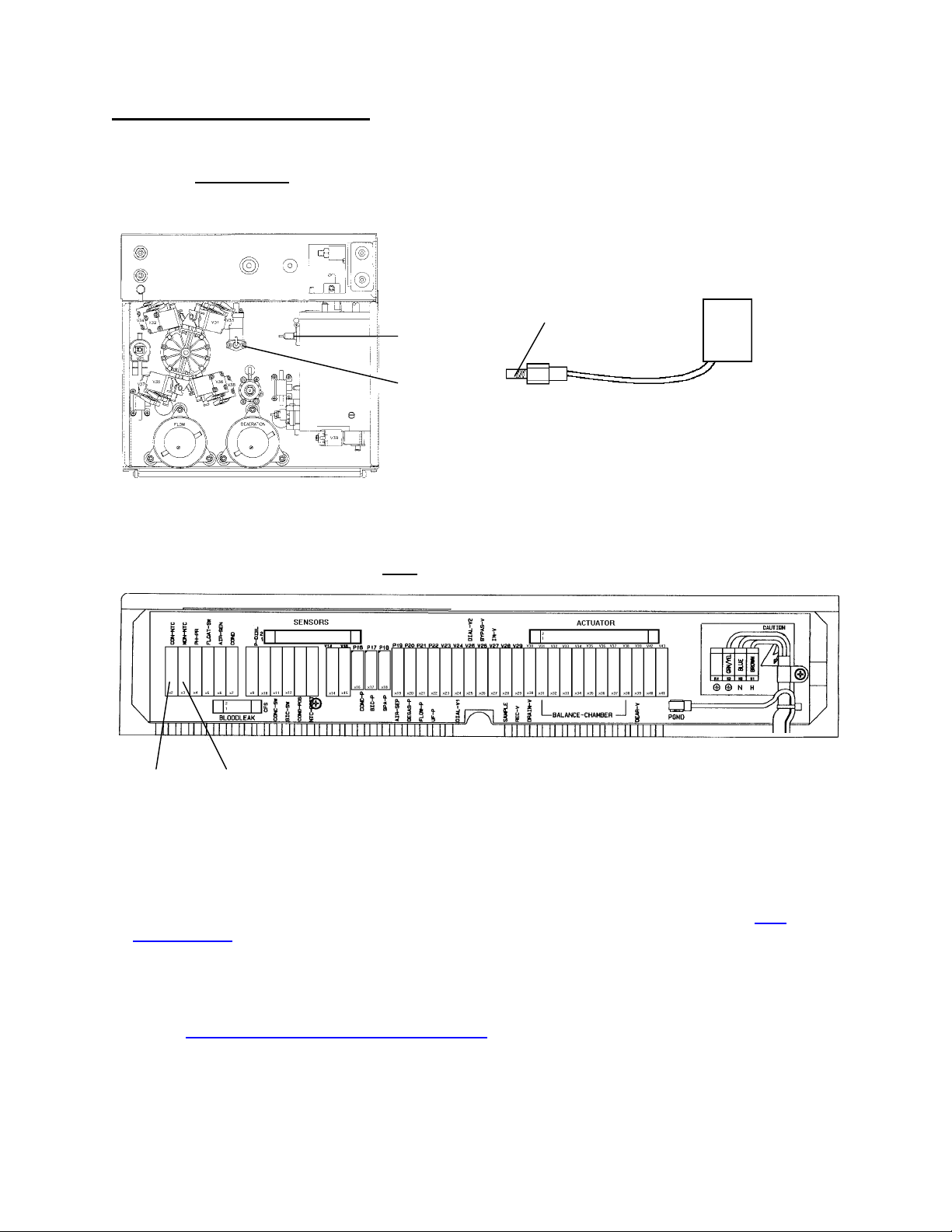
T- 9.0.0 CHECK NTC RESISTANCE
Proceed ONLY with the NTC(s) as noted above.
a) Turn the POWER OFF and remove the NTC(s) from the respective hydraulic location (see diagram below).
This reveals the 'probe' end.
DISTRIBUTION BOARD
CONNECTOR
NTC
PROBE END
NTC- 2
NTC- 3
HYDRAULICS, REAR VIEW
b) Unplug the NTC from its distribution board connector (see diagram below). Check, inside the distribution
board, for bent, broken, or corroded male pins.
NTC-2 NTC-3
c) VERY CAREFULLY! (thin wires inside!) open the plastic cover from the NTC's female connector. Clip
meter leads onto pins 1 and 3 (top and middle, typically green and white wires attached).
d) Draw water, between 36 and 38°C, into a styrofoam cup. Water temperature should be ACCURATELY
measured with an external thermometer.
e) Drop the 'probe' end into the water and allow the resistance value to stabilize. Refer to the NTC
RESISTANCE table (page 45). Replace any NTC that checks bad and calibrate HEAT TEMP CONTROL.
f) If NTC(s) check good there are four possibilities: 1) *Bad sensor board cable; 2) HEAT TEMP CONTROL
not calibrated accurately; 3) Bad sensor board; 4) Bad functional board.
* The sensor cable can be checked for continuity. Note that you are checking NTC-2 and NTC-3 connections
and see CHECKING THE SENSOR BOARD CABLE (page 74).
Page 44
Fresenius 2008H Troubleshooting Guide
P/N 507082 Rev. B
Page 50

NTC RESISTANCE
Temperature (
o
C) Low Resistance (KΩ)
Nominal Resistance
(KΩ)
High Resistance (KΩ)
36.0 6.142 6.267 6.392
36.1 6.117 6.242 6.367
36.2 6.092 6.217 6.342
36.3 6.067 6.192 6.317
36.4 6.042 6.167 6.292
36.5 6.017 6.142 6.267
36.6 5.992 6.117 6.242
36.7 5.967 6.092 6.217
36.8 5.942 6.067 6.192
36.9 5.917 6.042 6.167
37.0 5.892 6.017 6.142
37.1 5.868 5.993 6.118
37.2 5.844 5.969 6.094
37.3 5.820 5.945 6.070
37.4 5.796 5.921 6.046
37.5 5.772 5.897 6.022
37.6 5.748 5.873 5.998
37.7 5.724 5.849 5.974
37.8 5.700 5.825 5.950
37.9 5.676 5.801 5.926
38.0 5.652 5.777 5.902
Fresenius 2008H Troubleshooting Guide
P/N 507082 Rev. B
Page 45
Page 51

SECTION 5 - CONDUCTIVITY PROBLEMS
CO- 1.0.0 CHECK CONCENTRATE
a) If other machines are experiencing the same symptoms there may be a problem with the concentrate batch.
Use fresh bicarb.
b) From the VERIFY CONCENTRATE screen assure that the proper concentrate, Na and Bic levels are
selected. If not this may be the problem.
c) Assure that the concentrate connectors are plugged into the proper concentrates. If all is ok proceed to
CO- 1.0.1
CO- 1.0.1 CHECK FLOW/TEMPERATURE
a) Call up debug screen 5. If FLWERR = "1" a flow error is present. Do NOT troubleshoot CONDUCTIVITY
PROBLEMS until flow errors are clear.
b) Push SET to return to the main screen. Assure TEMP is stable and within (+/-) 0.3 of unit standards. Do
NOT troubleshoot CONDUCTIVITY PROBLEMS unless temperature is good.
c) If there are no flow errors or temperature problems proceed to CO- 1.0.2
CO- 1.0.2 CHECK FOR END OF STROKE (EOS) ERRORS
Call up debug screen 7. Is either NO EOS or ALWEOS ="1"?
Yes See CONCENTRATE PUMP END OF STROKE ERRORS (page 52).
No Proceed accordingly:
1) COND constantly low. See CO- 3.0.0
2) COND constantly high. See CO- 2.0.0
3) COND drifting from good to high. See CO- 2.0.0
4) COND rapidly bouncing from 10 to 17. See CO- 4.0.0 (page 48).
CO- 2.0.0 CHECK THE 'OUT OF BYPASS' HYDRAULIC CIRCUIT
Place the machine into RINSE and assure that the external flow indicator (75) is vertical. Is the' bob' (inside
the indicator) rising?
Yes See CO- 7.0.0 (page 50)
No A flow problem is indicated. See F- 17.0.0 (page 15).
Page 46
Fresenius 2008H Troubleshooting Guide
P/N 507082 Rev. B
Page 52

CO- 3.0.0 CHECK CONCENTRATE SELECTION
From the VERIFY CONCENTRATE screen is Bicarb or Acetate concentrate selected?
Bicarb See CO- 3.0.1
Acetate See CO- 3.0.2
CO- 3.0.1 CHECK BICARB STEPS
Call up debug screen 0. Is ABIC = "0"? IMPORTANT NOTE: If BIC also = "0" bicarb is NOT selected.
Yes See CO- 8.0.0 (page 51).
No See CO- 3.0.2
CO- 3.0.2 CHECK CONCENTRATE INLET
THIS IS AN IMPORTANT STEP! Looking through the acid and bicarb inlet lines (see diagram below) is AIR
FREE concentrate being pulled steadily, in one direction only (be certain)?
Yes See CO- 5.0.0 (page 49).
No See CO- 3.0.3
ACID REED
SWITCH
ACID INLET
LINE
BICARB INLET
CO- 3.0.3 CHECK CONCENTRATE CONNECTOR
a) Check the concentrate connector filter and o-ring #3 (see diagram below).
b) Place the machine into RINSE mode. Is either concentrate connector leaking?
Yes See CO- 3.0.4
No Allow the machine to run in RINSE for a few minutes (to remove a possible air lock) and
return to DIALYZE mode. If the pump still does not draw see CO- 3.0.4
CONCENTRATE CONNECTOR
MALE PROBE
CONNECTOR O-RING #3
BICARB REED
SWITCH
LINE
PROBE O-RING #1
Fresenius 2008H Troubleshooting Guide
INTERNAL O-RING #2
P/N 507082 Rev. B
CONNECTOR FILTER
Page 47
Page 53

CO- 3.0.4 CHECK CONNECTOR 0-RINGS
a) Check male probe o-rings #1 and #2 (see diagram, previous page).
b) If the pump still does not draw, place the entire concentrate connector into water. Does the pump draw
now?
Yes The wand is bad (see diagram below).
No Check the concentrate pump for broken springs, bad seals, bad o-rings, bad diaphragm (see
diagram below).
WAND
ACID PUMP
BICARB PUMP
HYDRAULICS, TOP VIEW
CO- 4.0.0 CHECK FOR AIR AT CONDUCTIVITY CELL
Check the clear tubing at both sides of the conductivity cell (see diagram, next page). Is there excessive air
flowing through it?
Yes a) Plug the bicarb connector back into it's port and wait for a few minutes. Check for air
again at the cell. If air is not seen a problem is indicated in the bicarb injection system.
Check first the bicarbonate connector for bad o-rings.
b) Calibrate DEAERATION PRESSURE by first decreasing the DAC value until pressure is
below -18 inHg and then increasing it SLOWLY to -24 inHg.
c) Perform NEGATIVE PRESSURE TESTS (page 62) and INDUCED POSITIVE
PRESSURE TESTS (page 65). Look for fluid leaks especially at balancing chamber
valves 31 and 33.
Page 48
No See CO- 4.0.1
Fresenius 2008H Troubleshooting Guide
P/N 507082 Rev. B
Page 54
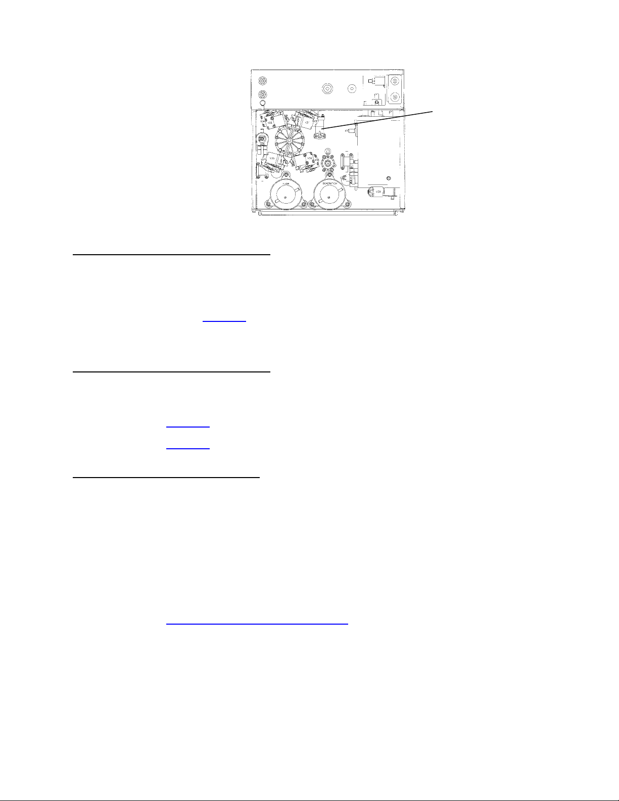
CONDUCTIVITY CELL
HYDRAULICS, REAR VIEW
CO- 4.0.1 CHECK DEBUG CELL VALUES
Assure that the machine has run for 10 minutes with fresh concentrate connected and call up debug screen
23 (frequency values in Hertz). Is FPRE between 1392 and 3072 Hertz or is it 'bouncing' to greater than 8000
Hertz?
Between See CO- 6.0.0
Bouncing Two possibilities; 1) Bad sensor board; 2) Bad actuator board.
CO- 5.0.0 CHECK DEBUG CELL VALUES
Assure that the machine has run for 10 minutes with fresh concentrate connected and call up debug screen
23 (frequency values in Hertz). Is FPRE 1392 and 3072 Hertz?
Yes See CO- 6.0.0
No See CO- 5.0.1
CO- 5.0.1 PERFORM PRESSURE TEST
a) Select a flow rate of 500 ml/min, clear blood alarms, and turn the blood pump rate knob clockwise.
b) Select a UF RATE of 1000 ml/hr and turn UF on (green UF on/off LED MUST be on solid and the UF RATE
numeric display must NOT blink).
c) Allow TMP increase to about 260 and then turn UF off. Allow 30 seconds for stabilization.
d) After stabilization does TMP remain stable (within +/- 60 mmHg) for three minutes?
Yes Check BALANCING CHAMBER VOLUME and calibrate *ACID and *BICARB PUMP
VOLUMES and CONDUCTIVITY CELL per CALIBRATION PROCEDURES.
No See PRESSURE HOLDING TESTS FAILING (page 60).
* While the pumps are drawing concentrate from the burette determine if each is taking CONSTANT volumes
per stroke (in one direction ONLY). If not check the pump's springs, seals, and diaphragm.
Fresenius 2008H Troubleshooting Guide
P/N 507082 Rev. B
Page 49
Page 55

CO- 6.0.0 CHECK CONDUCTIVITY CELL
a) Turn flow off and note the FPRE value.
b) Unplug the float from the distribution board (x5, FLOAT-SW) and plug it into the conductivity cell's position
(x7, COND). CAUTION Be sure to plug in correctly!
c) From debug screen 23 does the FPRE value go very high?
Yes Two possibilities: 1) Concentrate is bad or not being pulled by the concentrate pumps;
2) Bad conductivity cell (see diagram, previous page).
No Remains at previous value. Two possibilities: 1) *Bad sensor board cable; 2) Bad
distribution board connection (check carefully for corrosion).
* The sensor cable can be checked for continuity. Note that you are checking the COND CELL connection
and see CHECKING THE SENSOR BOARD CABLE (page 74).
CO- 7.0.0 CHECK DEBUG CONDUCTIVITY VALUE
Go to RINSE and call up debug screen 23. After 5 minutes does FPRE= 4000 or less?
Yes See CO- 7.0.1
No See CO- 7.0.3
CO- 7.0.1 PERFORM PRESSURE TEST
a) Place the machine into DIALYZE MODE. Select a flow rate of 500 ml/min, clear blood alarms and turn the
blood pump rate knob clockwise.
b) Select a UF RATE of 1000 ml/hr and turn UF on (green UF on/off LED MUST be on solid and the UF RATE
numeric display must NOT blink).
c) Allow TMP increase to about 260 and then turn UF off. Allow 30 seconds for stabilization.
d) After stabilization does TMP remain stable (within +/- 60 mmHg) for three minutes?
Yes See CO- 7.0.2
No See PRESSURE HOLDING TESTS FAILING (page 60).
CO- 7.0.2 CHECK FOR INTERMITTENT FLOW ERROR
Call up debug screen 5 and watch FLWERR very carefully for 10 minutes. Does FLWERR ever go to "1"
during this time interval?
Yes An intermittent flow error is indicated. See F- 9.0.0 (page 10).
No Check BALANCING CHAMBER VOLUME and calibrate *ACID and *BICARB PUMP
VOLUMES and CONDUCTIVITY CELL per CALIBRATION PROCEDURES.
* While the pumps are drawing concentrate from the burette determine if each is taking CONSTANT
volumes per stroke (in one direction ONLY). If not check the pump's springs, seals, and diaphragm).
Page 50
Fresenius 2008H Troubleshooting Guide
P/N 507082 Rev. B
Page 56

CO- 7.0.3 CHECK FOR 'SHORTED' CONDUCTIVITY CELL
a) Unplug the conductivity cell from the distribution board (position x7, COND) . Check, inside the distribution
board, for bent or corroded male pins.
b) Plug the 34°C Fresenius test (temperature) dummy connector into the cell's position (x7, COND).
CAUTION! Plug in correctly. From debug screen 23, FPRE =3000 or less?
Yes Replace the conductivity cell (see diagram, page 49).
No See CO- 7.0.4
CO- 7.0.4 CHECK SENSOR BOARD CABLE
a) Turn the power off and unplug both ends of the 34-pin sensor board cable. The sensor board is the smallest
board in the card cage (far right). The cable plugs into the top edge and runs into the distribution board.
b) Check for bent or corroded male pins at the sensor and distribution board connectors.
c) Leave the cable unplugged for now and turn the power on. From the SELECT PROGRAM screen push the
SET button ONCE and then call up debug screen 19. Is ACON= 3000 or less?
Yes The sensor board cable is bad.
No Two possibilities: 1) Bad sensor board; 2) Bad distribution board
CO- 8.0.0 CHECK BICARB DEBUG SIGNAL
The machine 'thinks' that the blue bicarb connector is plugged into it's port.
Call up debug screen 1. With the bicarb connector out of it's port does BICOUT = "1"
Yes Two possibilities; 1) Bad actuator board; 2) Bad functional board.
No See CO- 8.0.1
CO- 8.0.1 CHECK THE BICARB REED SWITCH
Unplug the bicarb reed switch from distribution board position x12, BIC-SW. Is BICOUT "1" now?
Yes Replace the bicarb reed switch (see diagram, page 47).
No a) Check inside the distribution board for bent or corroded male pins.
b) Unplug the sensor cable from both ends and check the female and male connectors for
corrosion.
c) Plug all cables back in and place the machine into dialyze mode. If the problem is still
present there are two possibilities; 1) Bad actuator board; 2) Bad functional board.
Fresenius 2008H Troubleshooting Guide
P/N 507082 Rev. B
Page 51
Page 57
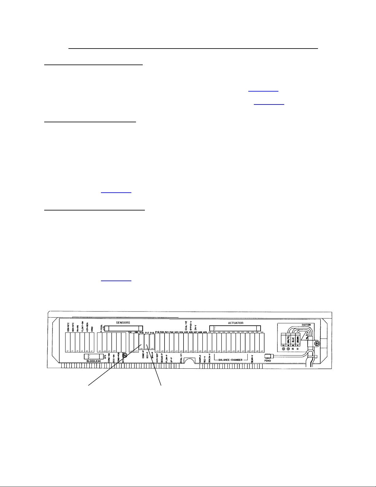
SECTION 6 - CONCENTRATE PUMP 'END OF STROKE' (EOS) ERRORS
(
)
EOS- 1.0.0 DETERMINE THE EOS
Call up debug screen 5:
ACEERR = "1", the ACID pump 'side' is issuing an EOS error. See EOS- 2.0.0
BICERR = "1", the BICARB pump 'side' is issuing an EOS error. See EOS- 3.0.0
EOS- 2.0.0 CHECK ACID PUMP
This procedure uses the bicarb pump (known good) to check the acid pump.
a) Switch the concentrate pump connectors at the distribution board (i.e. Turn the machine OFF then plug the
bicarb pump into acid pump's position and visa-versa, see diagram below).
b) Call up debug screen 0 and wait 30 seconds. Are ACID and AACI within 5 units of each other?
Yes Replace the acid pump (or see 2008H ACID & BICARBONATE REPAIR PROCEDURE).
No See EOS- 4.0.0
EOS- 3.0.0 CHECK BICARB PUMP
This procedure uses the acid pump (known good) to check the bicarb pump.
a) Switch the concentrate pump connectors at the distribution board (i.e. Turn the machine OFF then plug the
acid pump into bicarb pump's position and visa-versa, see diagram below).
b) Call up debug screen 0 and wait 30 seconds. Are BIC and ABIC within 5 units of each other?
Yes Replace the bicarb pump (or see 2008H ACID & BICARBONATE REPAIR PROCEDURE).
No See EOS- 4.0.0
DISTRIBUTION BOARD
ACID PUMP
P16, CONC-P
BICARB PUMP
(P17, BIC-P)
Page 52
Fresenius 2008H Troubleshooting Guide
P/N 507082 Rev. B
Page 58

EOS- 4.0.0 CHECK CONCENTRATE PUMP CIRCUIT
Four possibilities: 1) aBad actuator cable; 2) bBad sensor board cable; 3) Bad actuator board; 4) Bad
distribution board (check for corrosion).
a
The actuator cable can be checked. Which 'side' is issuing the error?
ACID The actuator cable can be checked for continuity. Note that you are checking ACID
PUMP connections and see CHECKING THE ACTUATOR BOARD CABLE
(page 72).
BICARB The actuator cable can be checked for continuity. Note that you are checking
BICARB PUMP connections and see CHECKING THE ACTUATOR BOARD CABLE
(page 72).
b
The sensor cable can be checked. Which 'side' is issuing the error?
ACID The sensor cable can be checked for continuity. Note that you are checking the ACID
EOS connection and see CHECKING THE SENSOR BOARD CABLE (page 74).
BICARB The sensor cable can be checked for continuity. Note that you are checking the
BICARB EOS connection and see CHECKING THE SENSOR BOARD CABLE
(page 74).
Fresenius 2008H Troubleshooting Guide
P/N 507082 Rev. B
Page 53
Page 59

SECTION 7 - COND OFFSET REF OR COND OFFSET FAILURES
Perform these procedures ONLY if the machine is issuing "COND OFFSET REF" or "COND OFFSET
FAILURE" messages upon power up.
NOTE: If you have changed the SENSOR or FUNCTIONAL board since the last COND CELL CALIBRATION
these failures are normal. Perform COND CELL CALIBRATIONS.
CR- 1.0.0 TROUBLESHOOTING OFFSET ERRORS
Attempt to calibrate CONDUCTIVITY CELL per CALIBRATION PROCEDURES. If unsuccessful there are
four possibilities: 1) *Bad test board; 2) Bad sensor board; 3) Bad actuator board; 4) Bad functional board.
* NOTE: An alternative to swapping the test board is to remove IC 30 from the test board and run the
machine without it. The machine runs ok without IC 30 but will fail tests.
Page 54
Fresenius 2008H Troubleshooting Guide
P/N 507082 Rev. B
Page 60

SECTION 8 - FILLING PROGRAM PROBLEMS
FI- 1.0.0 CHECK FLOW ERRORS
Call up debug screen 5. If FLWERR = "1" a flow error is present. Do NOT troubleshoot FILLING PROGRAM
PROBLEMS with flow errors present. If FLWERR = "0" proceed to FI- 1.0.1
FI- 1.0.1 CHECK TEMP/COND
Return to the main DIALYSIS screen. Do NOT troubleshoot FILLING PROGRAM PROBLEMS unless COND
and TEMP are normal and the BYPASS LED is off. If COND and TEMP are ok proceed to FI- 1.0.2.
FI- 1.0.2 CHECK DEBUG 'FILACT'
a) Assure that the dialysate lines are in the shunt and the shunt door is closed.
b) With TMP less than 100 call up debug screen 7. Is FILACT = "1" or "0"?
"1" See FI- 1.0.4
"0" A FILLING PROGRAM is currently not present. See FI- 1.0.3
FI- 1.0.3 FILLING PROGRAM CHECKS
Generally FILLING PROGRAMS are caused by air leaks. Perform both INDUCED POSITIVE PRESSURE
TESTS (page 65) AND NEGATIVE PRESSURE TESTS (page 62) to locate a leak if:
• the message "10 FILL PROGRAMS IN 1 HR" is coming up on the screen
• FILLING PROGRAM is occurring ONLY at high TMP values
FI- 1.0.4 CHECK AIR SENSOR
a) Assure that the two-pin female connector is plugged onto male probes at chamber 69 (see diagram below).
Brown at the top probe, blue at the bottom. If ok proceed.
b) Unplug the female connector and connect both ends together. Wait 30 seconds. Does FILACT = "0"?
Yes See FI- 1.0.5
No See FI- 1.0.6
VALVE 43
TWO-PIN FEMALE
CONNECTOR
MALE PROBES
CHAMBER 69
HYDRAULICS, FRONT VIEW
Fresenius 2008H Troubleshooting Guide
P/N 507082 Rev. B
Page 55
Page 61

FI- 1.0.5 CHECK CONNECTOR
Place the female connector back onto the probes (brown at top probe, blue at bottom) and wait 30 seconds.
Does FILACT remain "0"?
Yes a) Check the two-pin wiring female connector and harness for bare wires. Replace if bare.
b) Check for a 'tight' connection between the female connector and the male probes.
No FILACT = "1". If conductivity is normal a problem is indicated with the male probes.
FI- 1.0.6 CHECK AIR REMOVAL HARNESS
a) Unplug the air sensor connector from distribution board position x6, AIR-SEN. Check, inside the distribution
board, for bent, broken or corroded male pins.
b) Place a jumper wire, between male pins 1 and 5 (top and bottom). CAUTION! Make sure that you put the
jumper into the correct distribution board position. Does FILACT = "0"?
Yes The two-pin female connector is bad (open).
No See FI- 1.0.7
FI- 1.0.7 CHECK SENSOR BOARD
a) Place the female connector back onto the probes (brown at top probe, blue at bottom).
b) Plug the air sensor connector back into the distribution board position x6, AIR-SEN.
CAUTION! Be careful to plug in correctly.
c) Turn the power off go to T&C by turning on dipswitch 7 on the functional board.
d) Swap in a sensor board and turn the power back on. Return to DIALYZE MODE.
e) Wait until conductivity comes up and call up debug screen 7. Is FILACT "1" or "0"?
"1" Two possibilities: 1) *Bad sensor board cable; 2) Bad functional board.
0" The previous sensor board is bad.
* The sensor cable can be checked for continuity. Note that you are checking the AIR SENSOR connection
and see CHECKING THE SENSOR BOARD CABLE (page 74).
Page 56
Fresenius 2008H Troubleshooting Guide
P/N 507082 Rev. B
Page 62

SECTION 9 - TMP PROBLEMS
TM- 1.0.0 CHECK FOR FLOW ERROR
Call up debug screen 5. If FLWERR = "1" a flow error is present. Do NOT troubleshoot TMP PROBLEMS with
flow errors present. If FLWERR = "0" proceed to TM- 1.0.1
TM- 1.0.1 CHECK FOR FILLING PROGRAM
Call up debug screen 7. If FILACT = "1" a FILLING PROGRAM is present. Do NOT troubleshoot TMP
PROBLEMS until FILLING PROGRAM is clear. If FILACT = "0" proceed to TM- 1.0.2
TM- 1.0.2 CHECK TMP FAULT
Push SET to return to the main screen. Is TMP 'pegged' at either +60 or 520 mmHg?
Yes See TM- 1.0.3
No Perform pressure holding tests (negative flow on/positive flow off). If both pass a TMP
problem is not indicated.
TM- 1.0.3 ADJUST TMP
a) Push RESET. The message "ADJUST TMP?" comes up on the screen.
b) Push and hold RESET until "ADJUST TMP" is up. Does TMP move from it's previous value?
Yes See TM- 1.0.4
No See TM- 2.0.0
TM- 1.0.4 CHECK FOR TMP PEGGING
Does TMP return quickly (within 30 seconds) to it's previous 'pegged' value?
Yes See TM- 1.0.5
No Perform pressure holding tests (negative flow on/positive flow off). If both pass a TMP
problem is not indicated.
TM- 1.0.5 PERFORM PRESSURE TEST
This procedure will determine if a problem is located in the balancing chambers.
a) Adjust TMP from it's 'pegged' value, clear blood alarms, and turn the blood pump rate knob clockwise.
b) Select a UF RATE of 1000 ml/hr and turn UF on (green UF on/off LED MUST be on solid and the UF RATE
numeric display must not blink).
c) Allow TMP increase to about 260 and then turn UF off.
Fresenius 2008H Troubleshooting Guide
P/N 507082 Rev. B
Page 57
Page 63

d) Turn flow off and allow 30 seconds for stabilization. Does TMP remain stable (within +/- 40 mmHg) for three
minutes?
Yes See TM- 1.0.6
No Four possibilities:
1) Hydraulic leak. Perform both INDUCED POSITIVE PRESSURE TESTS (page 65) AND
NEGATIVE PRESSURE TESTS (page 62) to locate a possible leak;
2) Leaking valve. Perform VALVE LEAK TEST from SERVICE/DIAGNOSTICS;
3) Dialysate pressure out of calibration (see CALIBRATION PROCEDURES, section 2.3);
4) Bad dialysate pressure transducer #9 (see diagram A, page 5).
TM- 1.0.6 PERFORM VALVE LEAK TESTS
A problem is indicated in the balancing chambers.
a) Place the machine into SERVICE/DIAGNOSTICS.
b) Select #11 VALVE LEAK TEST and wait until the "READY" message appears.
c) Push SET twice to start the tests. Is a balancing chamber valve (valves 31 through 38) leak indicated?
Yes Unplug the leaking valve from the distribution board (for example, valve 36 plugs into position
V36) and measure for voltage, inside the distribution board, between male pins 1 and 5 (top
and bottom). If one vdc or greater replace the actuator board otherwise replace the indicated
leaking valve.
No See MANUAL BALANCING CHAMBER VALVE LEAK TESTS (page 76) if a leak is not found
perform TESTING FOR A LEAKING BALANCING CHAMBER DIAPHRAGM (page 79).
TM- 2.0.0 CHECK SENSOR BOARD DEBUG VALUE (PDIA)
a) Turn the flow off, remove the dialysate lines from the shunt and drop them into a bucket of water on the
floor.
b) Close the shunt door (important).
c) Call up debug screen 9. Is PDIA between 4.0 and 7.0 vdc?
Yes See TM- 2.0.3
No See TM- 2.0.1
TM- 2.0.1 CHECK ACTUATOR BOARD DEBUG VALUE (ADIA)
Call up debug screen 11. Is ADIA between 3.0 and 6.0 vdc?
Yes Replace the sensor board.
No See TM- 2.0.2
Page 58
Fresenius 2008H Troubleshooting Guide
P/N 507082 Rev. B
Page 64

TM- 2.0.2 CHECK DIALYSATE PRESSURE TRANSDUCER
This procedure tests the dialysate pressure transducer using the known good CFS transducer.
a) Unplug the CFS and dialysate pressure transducers from their respective distribution board positions (x10,
CFS)(x9, P-DIAL).
b) Plug the CFS connector into position x9, P-DIAL. CAUTION! Be sure to plug in correctly.
c) From debug screen 11. Does ADIA read between 3.0 and 6.0 vdc?
Yes Return the transducers to their correct distribution board positions (important). Calibrate
DIALYSATE PRESSURE per CALIBRATION PROCEDURES, section 2.3. If not successful
replace the dialysate pressure transducer #9 (see diagram A, page 5) and calibrate.
No See TM- 2.0.4
TM- 2.0.3 CHECK TMP
Push SET to return to the main screen. Is TMP between 0 and 100 mmHg?
Yes Return the lines to the shunt door and perform pressure holding tests (negative flow
on/positive flow off). If both pass a problem is not indicated.
No Calibrate DIALYSATE PRESSURE per CALIBRATION PROCEDURES, section 2.3. If not
successful replace the dialysate pressure transducer #9 (see diagram A, page 5) and
calibrate.
TM- 2.0.4 CHECK TEST BOARD
a) Leave the CFS transducer plugged into position x9, P-DIAL for now.
b) Turn the power off and swap in a new test board. NOTE An alternative is to remove IC 4 from the test
board. The machine runs fine without IC 4 but will fail tests.
c) Turn the power on and enter DIALYZE mode. From debug screen 11, is ADIA between 3.0 and 7.0 vdc?
Yes The previous test board (or IC 4) is bad. CAUTION! Make sure to plug the transducers back
into their correct distribution board positions.
No See TM- 2.0.5
TM- 2.0.5 CHECK DIALYSATE PRESSURE CIRCUIT
a) IMPORTANT return the transducers to their correct distribution board positions.
b) Four possibilities: 1) *Bad sensor board cable; 2) Bad sensor board; 3) Bad actuator board; 4) Bad
functional board.
* The sensor cable can be checked for continuity. Note that you are checking DIALYSATE TRANSDUCER
connections and see CHECKING THE SENSOR BOARD CABLE (page 74).
Fresenius 2008H Troubleshooting Guide
P/N 507082 Rev. B
Page 59
Page 65

SECTION 10 - PRESSURE HOLDING TESTS FAILING
NOTE: These procedures assume that DIALYSATE PRESSURE has been calibrated accurately.
PH- 1.0.0 CHECK LOADING PRESSURE
Insert the loading pressure gauge tightly into the ACID/ACETATE port. This pressure should be between 18
and 20 psi. Calibrate as necessary and run PRESSURE HOLDING TESTS again. If loading pressure is ok
proceed to PH- 1.0.1
PH- 1.0.1 CHECK FOR LEAKS
Look for obvious fluid leaks inside the hydraulic compartment and at the external dialysate lines (especially
the hansen connectors). If a leak is not seen proceed to PH- 1.0.2
PH- 1.0.2 CHECK DEAERATION
a) Turn the flow off and wait 60 seconds or until you hear the deaeration pump turn off.
b) Tee a negative pressure gauge between the clear (INPUT) line and the deaeration pump's input nozzle
(see diagram, page 63).
c) Turn flow on at a 500 flow rate. Deaeration pressure -24 inHg to -25 inHg?
Yes See PH- 1.0.3
No See DEAERATION PROBLEMS (page 66).
PH- 1.0.3 PERFORM INDUCED POSITIVE PRESSURE TESTS
Read this entire step before proceeding. Run INDUCED POSITIVE PRESSURE TESTS (page 65) to locate a
possible fluid leak. If a leak not seen proceed to PH- 1.0.4
PH- 1.0.4 PERFORM TMP PUMP UP
a) Clear ALL blood alarm messages and turn the blood pump rate above 90 mL/min.
b) Select a UF RATE of 1000 ml/hr and turn UF on (green UF on/off LED MUST be on solid and the UF RATE
numeric display MUST NOT blink). Does TMP increase to 280 or greater?
Yes Run NEGATIVE PRESSURE TESTS (page 62) to locate a possible air leak. If a leak is not
found see PH- 1.0.6
No See PH- 1.0.5
PH- 1.0.5 CHECK UF PUMP
CLEAR all blood alarms. With UF ON determine if the UF pump is stroking by checking compressions of the
large external spring (see diagram, page 62). Is the pump stroking?
Yes See PH- 1.0.6
Page 60
No See UF PUMP PROBLEMS (page 67).
Fresenius 2008H Troubleshooting Guide
P/N 507082 Rev. B
Page 66

PH- 1.0.6 VALVE LEAK TESTS
a) Place the machine into SERVICE/DIAGNOSTICS. Select #11 VALVE LEAK TEST and wait until the
"READY" message appears.
b) Push SET TWICE to start the tests. Valve leak indicated?
Yes Run VALVE LEAK TEST AGAIN on the bad valve to confirm. If it fails again see PH- 1.0.7
No Return to DIALYZE MODE and run PRESSURE HOLDING TESTS (negative flow on/positive
flow off). If still failing see PH- 1.0.9
PH- 1.0.7 DETERMINE THE LEAK
"VALVE 44 FAILURE": Perform INDUCED POSITIVE PRESSURE TESTS (page 65) and check for a
fluid leak especially in the vicinity of air removal chamber #69 (see diagram, page 65).
ONE VALVE LEAKING: See PH- 1.0.8
VALVES 29/30 LEAKING: May also indicate a leaking heat exchanger. TIGHTLY clamp the tubing at
the input nozzles of valve 30 AND 29 (see diagram, page 62) and run VALVE LEAK TESTS again. If
the test fails the heat exchanger is leaking (see diagram, page 65). If the test passes remove the
clamp from valve 30 only and run VALVE LEAK TESTS once again. If the test fails valve 30 may be
leaking (see PH- 1.0.8). If the test passes valve 29 may be leaking (see PH- 1.0.8
MORE THAN ONE VALVE LEAKING: a) Check UF pump check valves #63 and #64 (see diagram,
page 67); b) Perform both INDUCED POSITIVE PRESSURE TESTS (page 65) AND NEGATIVE
PRESSURE TESTS (page 62) to locate a possible fluid leak; c) Calibrate DIALYSATE PRESSURE
per CALIBRATION PROCEDURES, section 2.3.
).
PH- 1.0.8 CHECK FOR SHORTED ACTUATOR BOARD VALVE DRIVER
Leave the machine in DIAGNOSTICS with the failure message on the screen. Unplug the indicated leaking
valve from the distribution board (for example, valve 33 plugs into position V33) and measure dc voltage
between male pins 1 and 5 (top and bottom) inside the distribution board. One vdc (or greater) replace the
actuator board otherwise replace the leaking valve.
PH- 1.0.9 MANUAL PRESSURE TEST
a) Select a flow rate of 500 ml/min, clear all blood alarms and turn the blood pump rate knob clockwise.
b) Select a UF RATE of 1000 ml/hr and turn UF on (green UF on/off LED MUST be on solid and the UF RATE
numeric display MUST NOT blink).
c) Allow TMP increase to about 260 and then turn UF off. Turn FLOW OFF and allow 30 seconds for
stabilization. Does TMP remains stable (within +/- 40 mmHg) for three minutes?
Yes A leak in the balancing chamber is indicated. Perform MANUAL BALANCING CHAMBER
VALVE LEAK TESTS (page 76). If a leaking valve is not found perform TESTING FOR A
LEAKING BALANCING CHAMBER DIAPHRAGM (page 79).
No Perform both INDUCED POSITIVE PRESSURE TESTS (page 65) AND NEGATIVE
PRESSURE TESTS (page 62) to locate a possible fluid leak.
Fresenius 2008H Troubleshooting Guide
P/N 507082 Rev. B
Page 61
Page 67

SECTION 11 - NEGATIVE PRESSURE TESTS
These tests use negative pressure to locate a hydraulic leak.
I. It is assumed that deaeration pressure has been previously checked to -24 inHg to -25 inHg.
II. Using a flashlight is helpful. All checks are done by looking through clear hydraulic tubing.
A- 1.0.0 CHECK FOR AIR LEAK
a) Assure that the dialysate lines are in the shunt and the door is closed.
b) Clear ALL dialysate and blood alarms and turn the blood pump rate knob fully clockwise.
c) Select a UF RATE of about 1000 ml/hr and turn the UF on (the green UF on/off LED MUST be on solid and
the UF RATE numeric display MUST NOT blink).
d) Allow the TMP to increase to about 260 and turn the UF off.
NOTE: A TMP of 300 (or greater) should be maintained to run these tests. Air bubbles are larger and much
easier to see at higher TMP.
e) Look through the clear tubing at the OUTPUT of the blood leak detector tubing (see diagram below), are
*large air bubbles seen?
Yes See A- 1.0.1
No An air leak is not obvious using this test. Return to previous procedures and proceed
accordingly
* Smaller air bubbles may be 'normal'. Check another machine (that is passing pressure holding tests) to
determine what 'normal' looks like.
HYDRAULICS, TOP VIEW
UF PUMP
EXTERNAL SPRING
V24/V26 JUNCTION
BLOCK
BLOOD LEAK
DETECTOR
OUTPUT TUBING
VALVE 29
INPUT NOZZLE
VALVE 30
INPUT NOZZLE
Page 62
OUTPUT TUBING AT VALVES 31 AND 33
Fresenius 2008H Troubleshooting Guide
P/N 507082 Rev. B
Page 68
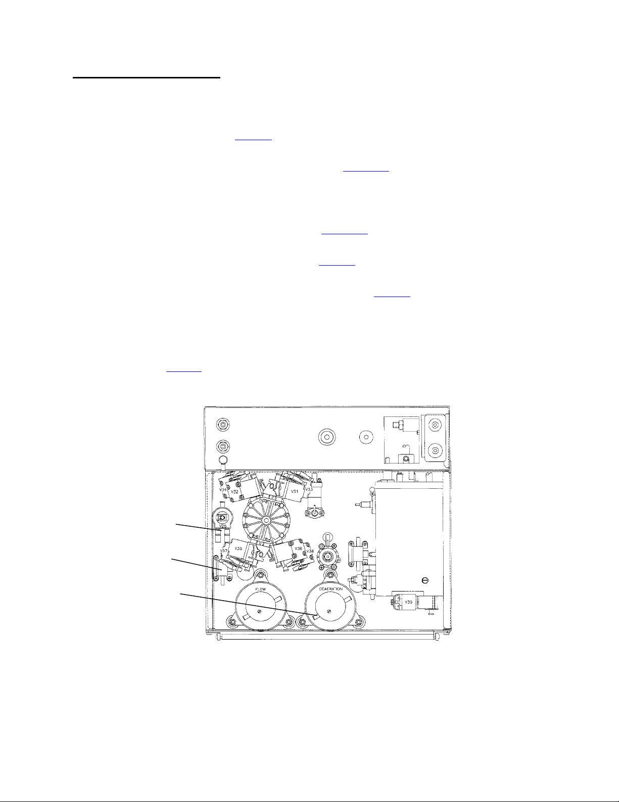
A- 1.0.1 LOCATING THE LEAK
Check for air bubbles at the following locations in the following order:
NOTE: TMP must be maintained at about 300 for these tests.
1. OUTPUT tubing at valve 25 (see diagram below). If air is not seen check the tubing connections at the
blood leak detector and dialysate pressure transducer.
2. INPUT tubing at the external dialysate line filter (73) (see diagram A, page 5). If air is not seen check the oring inside the filter housing.
3. INPUT tubing at the venous (blue) hansen connector. If air is not seen replace the hansen connector orings
4. INPUT tubing at the external flow indicator (75) (see diagram A, page 5). If air is not seen check the o-rings
inside the indicator.
5. INPUT tubing at the valve 24/26 junction block (see diagram, previous page). If air is not seen check the
block for bad o-rings or cracks.
6. OUTPUT tubing from balancing chamber valves 31 and 33 (see diagram, previous page). If air is not seen
check the tubing connections at the conductivity cell #7.
7. Is air coming from ONE or BOTH valves 31 and 33?
One Check the connection (and o-ring) between the leaking valve and the balancing chamber.
Both See A- 1.0.2
VALVE 25 (OUTPUT)
DIALYSATE PRESSURE
TRANSDUCER
INPUT NOZZLE
DEAERATION PUMP
HYDRAULICS, REAR VIEW
Fresenius 2008H Troubleshooting Guide
P/N 507082 Rev. B
Page 63
Page 69

A- 1.0.2 CHECK BICARB INLET SYSTEM
a) Check the clear bicarb inlet line for air. If air is seen check for a loose connection or bad o-rings at the
bicarb connector.
b) Plug the bicarbonate connector back into it's port. After a few minutes check at balancing chamber valves
31 and 33. Is air still present?
Yes a) Calibrate DEAERATION PRESSURE by first decreasing the DAC value until pressure is
below -18 inHg and then increasing it SLOWLY until -24 inHg is obtained.
b) Perform both the INDUCED POSITIVE PRESSURE TESTS (page 65) AND NEGATIVE
PRESSURE TESTS (page 62) to locate a possible leak (especially at balancing chamber
valves 31 and 33).
No Check the bicarb pump (o-rings), the injection site, and the mixing chamber #82 for an air
leak.
Page 64
Fresenius 2008H Troubleshooting Guide
P/N 507082 Rev. B
Page 70
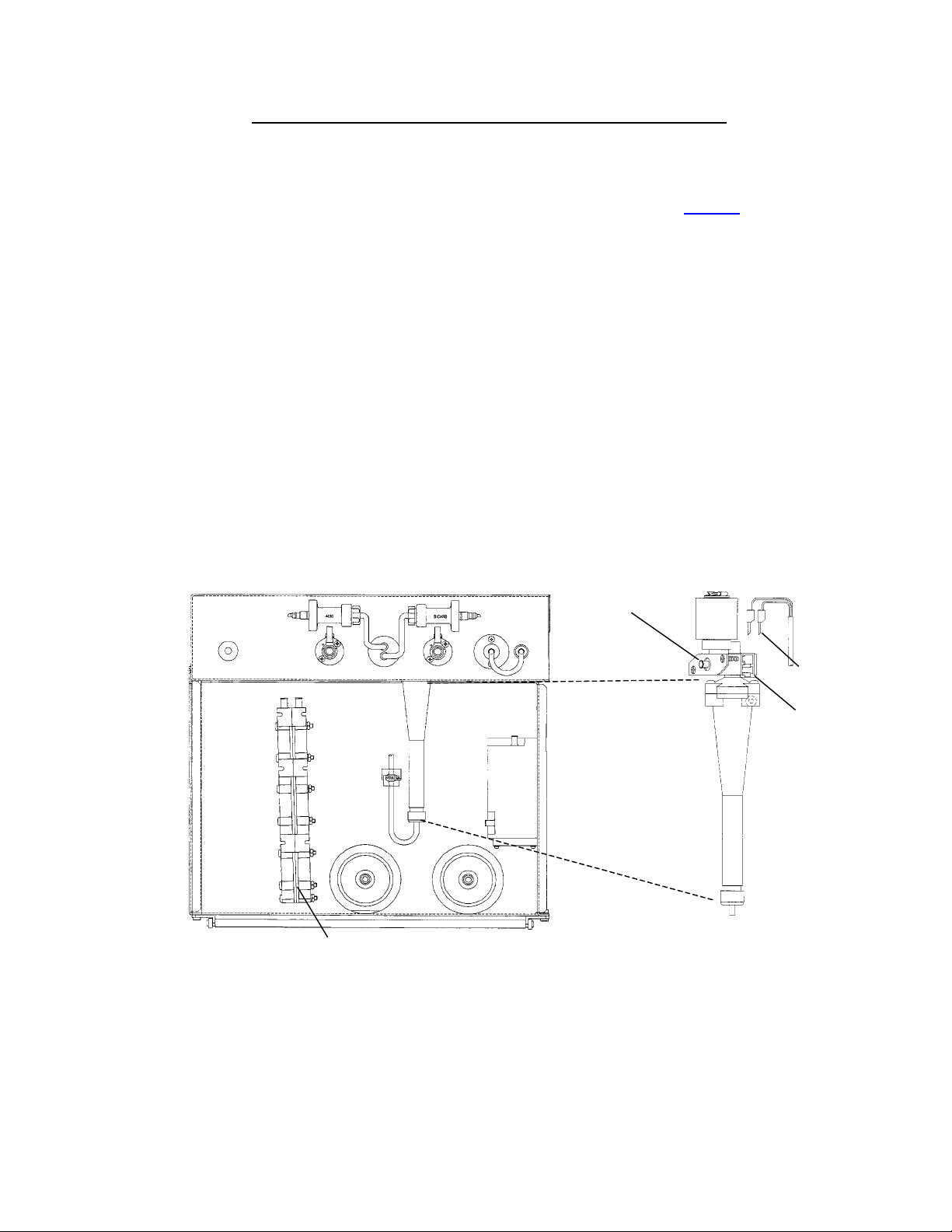
SECTION 12 - INDUCED POSITIVE PRESSURE TESTS
These tests use positive pressure to locate a hydraulic leak.
NOTE: These tests must be done from DIALYZE MODE.
a) At the top of the air removal chamber #69 is valve 43 and two male probes (see diagram below).
b) Unplug the two-pin female connector from each probe and place them such that they cannot come into
contact with each other. A FILLING PROGRAM should be now be present (debug screen 7, FILACT = "1").
c) Clamp the clear tubing from valve 43's output nozzle. During FILLING PROGRAM the only path to drain is
through valve 43. By clamping valve 43 this path is removed and the secondary hydraulic side is
pressurized to loading pressure (+19 ± 1 psi).
d) A flow error should become present (debug screen 5, FLWERR = 1). Push the SET key. TMP should = +60.
e) Remove the UF sample tube from the front of the machine and check for fluid leaks indicative of a bad UF
pump output spring AND check valve #63.
f) Wait for SEVERAL minutes and then CAREFULLY search for fluid leaks. Look ESPECIALLY in the area of
air removal chamber #69, flow pump tubing (input and output) and the flow pump regulator #78.
g) If a leak is not seen return the female connectors to the air removal chamber probes, unclamp valve 43, and
return to previous procedures.
HYDRAULICS, FRONT VIEW
HEAT EXCHANGER
VALVE 43
OUTPUT NOZZLE
TWO-PIN FEMALE
CONNECTOR
MALE PROBES
CHAMBER #69
Fresenius 2008H Troubleshooting Guide
P/N 507082 Rev. B
Page 65
Page 71
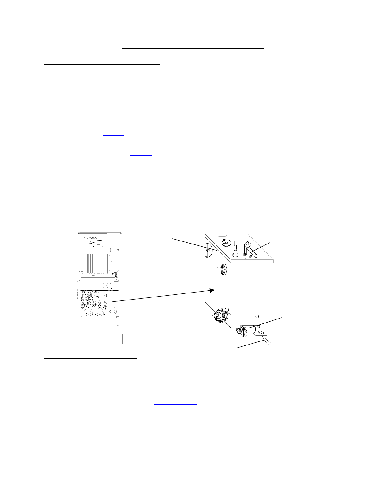
SECTION 13 - DEAERATION PROBLEMS
D- 1.0.0 CHECK DEAERATION SYSTEM
a) Turn flow off and call up debug screen 17. Wait until DEAP = 255 and check the deaeration pump's motor
shaft (diagram on page 6). If still rotating replace the actuator board (bad driver), otherwise proceed to part
b.
b) Attempt DEAERATION CALIBRATION per procedure. If unsuccessful proceed to part c.
c) Clamp the solid tubing between valve 39 and the hydroblock (see diagram below) and attempt
DEAERATION CALIBRATION again. Calibrate properly?
Yes See D- 1.0.2
No Replace the deaeration pump head and attempt DEAERATION CALIBRATION. If not
successful see D- 1.0.3 (the previous pump head is probably good).
D- 1.0.2 CHECK ACTUATOR BOARD
Remove the clamp from valve 39. Unplug valve 39 from the distribution board (V39, DEAR-V). Deaeration
pressure return to good?
Yes Replace the actuator board.
No Replace valve 39.
HYDROBLOCK SEAL
VENT TUBE
HYDROBLOCK
VALVE 39
D- 1.0.3 CHECK HYDROBLOCK
a) Turn the flow off and unplug the float from the distribution board (x5, FLOAT-SW). Place a jumper wire,
inside the distribution board, between male pins 1 and 3 (top and middle). Water should eventually
overflow from the vent tube.
b) Clamp the vent tube to pressurize the hydroblock to inlet water pressure (19 ± 1 psi) and look for a fluid leak
at the top seal of the hydroblock (see HYDROBLOCK diagram above). Is a leak seen?
TUBING TO HYDROBLOCK
(CLAMP HERE)
Page 66
Yes Try tightening the screws that mounts the hydroblock cover to the hydroblock. If the leak
continues replace the hydrobock seal (part # 565642).
No Two possibilities: 1) Bad actuator board; 2) Bad deaeration pump motor
Fresenius 2008H Troubleshooting Guide
P/N 507082 Rev. B
Page 72
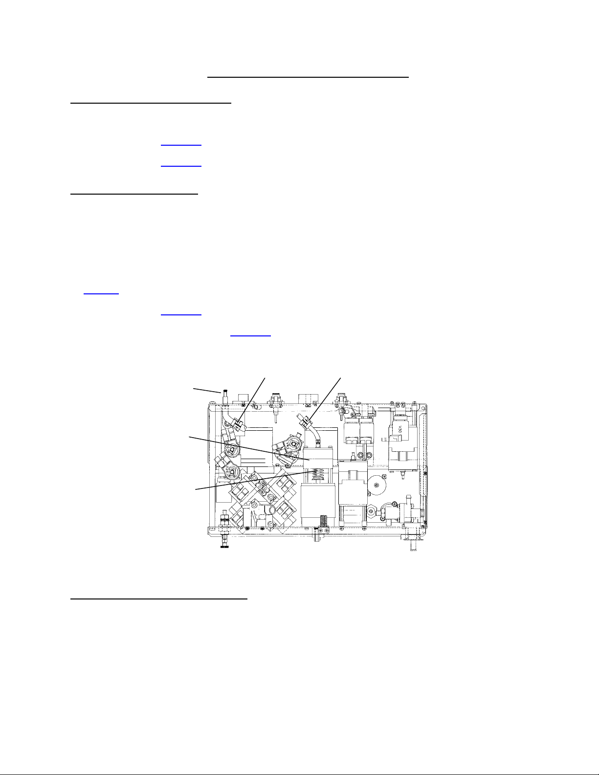
SECTION 14 - UF PUMP PROBLEMS
UF- 1.0.0 CHECK DEBUG UFPULS
With UF OFF (important) call up debug screen 1. Is UFPULS = "1"?
Yes See UF- 2.0.0
No See UF- 1.0.1
UF- 1.0.1 CHECK UF PUMP
a) Place the dialysate lines into a bucket of (conductive) water.
b) Clear all blood alarms and turn the blood pump rate knob fully clockwise.
c) Select a UF RATE of 1000 ml/hr and turn UF on (IMPORTANT the green UF on/off LED MUST remain on
solid and the UF RATE numeric display MUST NOT blink).
d) Determine if the UF pump is stroking by watching for compressions of the large external spring (see
diagram below). Is the UF pump stroking?
Yes See UF- 1.0.3
No Turn UF off and see UF- 1.0.2
CHECK VALVE #64
UF SAMPLE PORT
UF PUMP
EXTERNAL SPRING
CHECK VALVE #63
HYDRAULICS, TOP VIEW
UF- 1.0.2 CHECK ACTUATOR BOARD
a) Remove the cover from the UF pump's distribution board connector (P22, UF-P) and then plug the
connector back in. CAUTION Be careful to plug in correctly!
b) Clamp meter leads between pins 1 and 5 (top and bottom, where the wires are attached).
c) Clear all alarms and turn UF on (green UF on/off LED MUST be on solid and the UF RATE numeric display
MUST NOT blink). UF rate set to 1000 ml/hr.
Fresenius 2008H Troubleshooting Guide
Page 67
P/N 507082 Rev. B
Page 73

d) Voltage to the connector should 'pulse' from between 26 and 22 vdc to less than 2 vdc. Is this ok?
Yes Replace the UF pump.
No Replace the actuator board.
UF- 1.0.3 CHECK UF OUTPUT
With UF on, remove the UF output tube from the sample port (see diagram, previous page). Are there 'strong'
output strokes from the tube?
Yes See UF- 1.0.4
No a) Make sure check valve #63 is oriented properly (see diagram, previous page).
b) Check the UF pump for broken springs, bad o-rings, or a bad diaphragm.
UF- 1.0.4 CHECK TMP PUMP UP
a) Turn UF off and place the dialysate lines back into the shunt.
b) Clear all blood alarms and turn UF on. Does TMP (main screen) increase to 280 or greater?
Yes Make sure check valve #64 is oriented properly (see diagram, previous page).
No See UF- 1.0.5
UF- 1.0.5 CHECK DIALYSATE PRESSURE
a) Turn UF off and tee a three-way connector into the dialysate lines with one leg going to an external
pressure meter.
b) Clear all blood alarms and turn UF on. Does meter pressure increase to greater than -260 mmHg?
Yes Calibrate DIALYSATE PRESSURE per CALIBRATION PROCEDURES, section 2.3.
No Perform both NEGATIVE PRESSURE TESTS (page 62) AND INDUCED POSITIVE
PRESSURE TESTS (page 65) to locate a hydraulic leak.
UF- 2.0.0 CHECK UF PUMP SOLENOID RESISTANCE
a) Unplug the UF pump from distribution board position P22, UF-P.
b) Remove the plastic cover and measure resistance between the two soldered wires inside the female
connector. Between 8 and 12 ohms?
Yes Two possibilities: 1) *Bad actuator board cable; 2) Bad actuator board.
No Replace the UF pump.
* The actuator cable can be checked for continuity. Note that you are checking UF PUMP connections and
see CHECKING THE ACTUATOR BOARD CABLE (page 72).
Page 68
Fresenius 2008H Troubleshooting Guide
P/N 507082 Rev. B
Page 74

SECTION 15 - BLOOD LEAK PROBLEMS
NOTE: Do not proceed unless the BYPASS LED is off (i.e. out of bypass).
BL- 1.0.0 CHECK DIMNESS
Call up debug screen 9. If DIMN is greater than 5.5 or less than 4.0 vdc check the blood leak detector's glass
tube for calcium (the tube appears 'cloudy') and air bubbles. If calcium is seen run BLEACH/RINSE. If air is
seen perform NEGATIVE PRESSURE TESTS and/or INDUCED POSITIVE PRESSURE TESTS
leak.
BLOOD LEAK TUBE
(INSIDE HOUSING)
to locate the
HYDRAULICS, TOP VIEW
BL- 2.0.0 CHECK LEAK
From debug screen 9, if LEAK is greater than 5.2 or less than 4.5 vdc attempt BLOOD LEAK calibrations
(DETECTOR and DIMNESS, sections 2.6.1 and 2.6.2, CALIBRATION PROCEDURES).
BL- 3.0.0 CHECK BLOOD LEAK SIGNALS
a) Turn the power off and place a ground lead at TEST connector SGND (see CARD CAGE diagram, page 71).
b) Unplug the blood leak detector from the distribution board's x8 connector. Measure dc voltages at the male
pins specified in the BLOOD LEAK SIGNALS table (page 70). Follow the instruction given.
DISTRIBUTION BOARD
246810
X8 CONNECTOR
1357 9
Fresenius 2008H Troubleshooting Guide
P/N 507082 Rev. B
Page 69
Page 75

BLOOD LEAK SIGNALS (at x8 connector)
PIN GOOD (vdc) BAD
3 (+12V) 11.4 to 12.6, measure at pin 6 Sensor board cable
1
6 (TEST) Between 0 and 1, measure at pin 7
Sensor board cable or test board (IC 44)
See DAC PROCEDURE:
7 (LEAK)
a) With DAC set at " 255" voltage =
between 9.5 and 10.0
2
Sensor cable or sensor board (IC 6)
b) With DAC set at "0" voltage =
between 0 and 0.5, measure at pin 9
See DAC PROCEDURE:
9 (DIMN)
a) With DAC set at " 255" voltage =
between 9.5 and 10.0
3
Sensor cable or sensor board (IC 6)
b) With DAC set at "0" voltage =
between 0 and 0.5, see BL- 4.0.0
1
The sensor cable can be checked for continuity. Note that you are checking the BLOOD LEAK TEST
connection and see CHECKING THE SENSOR BOARD CABLE (page 74)
2
The sensor cable can be checked for continuity. Note that you are checking the BLOOD LEAK SENSOR
connection and see CHECKING THE SENSOR BOARD CABLE (page 74)
3
The sensor cable can be checked for continuity. Note that you are checking the BLOOD LEAK DIMNESS
connection and see CHECKING THE SENSOR BOARD CABLE (page 74)
DAC PROCEDURE
Place the machine into SERVICE mode and enter DIAGNOSTICS/7, OUTPUT TO D TO A. There are two
parts to this procedure:
PART I (While measuring voltage at connector x8, pin 7).
a) Select and change the BLOOD LEAK CAL value to "255".
b) Move the pointer in front of BLOOD LEAK CAL (as shown) and PRESS the SET button.
WARNING! Not pushing SET results in incorrect voltages.
c) Repeat procedure, this time setting BLOOD LEAK CAL to "0". Move the pointer in front and PRESS the
SET button.
WARNING! Not pushing SET results in incorrect voltages.
Page 70
Fresenius 2008H Troubleshooting Guide
P/N 507082 Rev. B
Page 76

PART II (While measuring voltage at connector x8, pin 9).
a) Select and change the DIMNESS CAL value to "255".
b) Move the pointer in front of DIMNESS CAL (as shown) and PRESS the SET button. WARNING! Not
pushing SET results in incorrect voltages.
c) Repeat procedure, this time setting DIMNESS CAL to "0". Move the pointer in front and PRESS the SET
button. WARNING! Not pushing SET results in incorrect voltages.
BL- 4.0.0 CHECK SENSOR BOARD BLOOD LEAK OUTPUT
a) Turn the power off and take the machine out of SERVICE mode.
b) Plug the blood leak detector back into the distribution board.
c) Turn the power back on and return to DIALYZE mode.
d) Measure voltage, from the back (solder) side of the sensor board's, x2 connector at pin 6 (see diagram
below). Between 4.5 and 5.2 vdc?
Yes Currently a problem is NOT indicated. Possible intermittent blood leak sensor.
No Two possibilities: 1) 4Sensor board cable; 2) Bad blood leak detector.
4
The sensor cable can be checked for continuity. Note that you are checking the BLOOD LEAK OUTPUT
connection and see CHECKING THE SENSOR BOARD CABLE (page 74)
CARD CAGE
TEST CONNECTOR
(FOR GROUND)
PIN 6 (SOLDER
SIDE, TOP ROW,
3 PINS FROM REAR)
SENSOR BOARD
x2 CONNECTOR
Fresenius 2008H Troubleshooting Guide
Page 71
P/N 507082 Rev. B
Page 77

SECTION 16 - CHECKING THE ACTUATOR BOARD CABLE
a) Turn the POWER OFF and unplug the actuator board cable from the distribution board (ACTUATOR
CONNECTOR).
b) Using a flashlight, check inside the male connector for bent or broken pins. Check also for signs of
corrosion.
c) Check the female cable end for signs of corrosion. The cable ends are arranged in two rows, even in one
row, odd in the other. The TAB identifies the 'odd' row.
FEMALE CONNECTOR
REAR OF MACHINE
d) Inside the card cage the cable terminates at connector X2 (actuator board). The solder (back) side pins of
this connector are arranged in two rows. Unplug the cable from the connector and check inside the male
connector for corrosion or bent pins. Replace cable when check is complete.
IMPORTANT NOTE: A regular meter probe does not penetrate deep enough to make a connection. Do NOT
use a paper clip or you may damage the connector.
e) Clip one meter lead to a metal object small enough to fit loosely into the holes of the connector. This will be
used as our 'probe'. Count to the indicated female pin (see table, next page) and stick the 'probe' into it.
f) Place the second meter lead on the matching numbered pin (see table, next page) on the solder side of the
connector. A good connection will measure 10Ω or less.
X2 CONNECTOR
PIN 2 (TOP ROW)
PIN 1 (BOTTOM ROW)
ACTUATOR BOARD
(SOLDER SIDE)
REAR OF MACHINE
CARD CAGE
Page 72
Fresenius 2008H Troubleshooting Guide
P/N 507082 Rev. B
Page 78

ACTUATOR BOARD, P2 CABLE, PIN IDENTIFICATION (PUMPS)
(
)
PUMP P2 PIN # P2 LOCATION
DEAERATION PUMP
1 of 2
DEAERATION PUMP
(2 of 2)
FLOW PUMP (1 of 2) 19 Bottom row, 10 pins from rear
FLOW PUMP (2 of 2) 20 Top row, 10 pins from rear
ACID PUMP (1 of 4) 1 Bottom row, first pin from rear
ACID PUMP (2 of 4) 2 Top row, first pin from rear
ACID PUMP (3 of 4) 3 Bottom row, 2 pins from rear
ACID PUMP (4 of 4) 4 Top row, 2 pins from rear
BICARB PUMP (1 of 4) 5 Bottom row, 3 pins rom rear
BICARB PUMP (2 of 4) 6 Top row, 3 pins from rear
BICARB PUMP (3 of 4) 7 Bottom row, 4 pins from rear
BICARB PUMP (4 of 4) 8 Top row, 4 pins from rear
15 Bottom row, 8 pins from rear
16 Top row, 8 pins from rear
UF PUMP (1 of 4) 23 Bottom row, 12 pins from rear
UF PUMP (2 of 4) 24 Top row, 12 pins from rear
UF PUMP (3 of 4) 25 Bottom row, 13 pins from rear
UF PUMP (4 of 4) 26 Top row, 13 pins from rear
ACTUATOR BOARD, P2 CABLE, PIN IDENTIFICATION (VALVES)
VALVE P2 PIN# P2 LOCATION
24 29 Bottom row, 11 pins from front
41 (27) 32 Top row, 10 pins from front
43 46 Top row, 3 pins from front
39 44 Top row, 4 pins from front
29 34 Top row, 9 pins from front
Fresenius 2008H Troubleshooting Guide
P/N 507082 Rev. B
Page 73
Page 79

SECTION 17 - CHECKING THE SENSOR BOARD CABLE
a) Turn the POWER OFF and unplug the smaller sensor board cable from the distribution board (SENSORS
CONNECTOR).
b) Using a flashlight, check inside the male connector for bent or broken pins. Check also for signs of
corrosion.
c) Check the female cable end for signs of corrosion. The cable ends are arranged in two rows, even in one
row, odd in the other. The TAB identifies the 'odd' row.
FEMALE CONNECTOR
REAR OF MACHINE
d) Inside the card cage the cable terminates at connector X2 (sensor board). The solder (back) side pins of
this connector are arranged in two rows. Unplug the cable from the connector and check inside the male
connector for corrosion or bent pins. Replace cable when check is complete.
IMPORTANT NOTE: A regular meter probe does not penetrate deep enough to make a connection. Do NOT
use a paper clip or you may damage the connector.
e) Clip one meter lead to a metal object small enough to fit loosely into the holes of the connector. This will be
used as our 'probe'. Count to the indicated female pin (see table, next page) and stick the 'probe' into it.
f) Place the second meter lead on the matching numbered pin (see table, next page) on the solder side of the
connector. A good connection will measure 10 Ω or less.
X2 CONNECTOR
PIN 2 (TOP ROW)
PIN 1 (BOTTOM ROW)
SENSOR BOARD
(SOLDER SIDE)
REAR OF MACHINE
CARD CAGE
Page 74
Fresenius 2008H Troubleshooting Guide
P/N 507082 Rev. B
Page 80
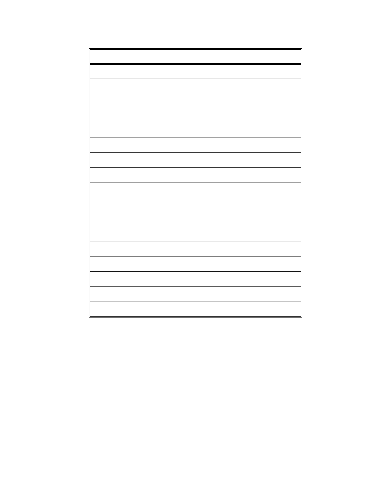
SENSOR BOARD, x2 CABLE, PIN IDENTIFICATION
DEVICE x2 PIN # x2 LOCATION
NTC-3 12 Top row, 6 pins from rear
NTC-2 13 Bottom row, 7 pins from rear
FLOAT 21 Bottom row, 7 pins from front
CFS TRANSDUCER
(1 of 3)
CFS TRANSDUCER
(2 of 3)
CFS TRANSDUCER
(3 of 3)
COND CELL 16 Top row, 8 pins from rear
ACID EOS 25 Bottom row, 5 pins from front
BICARB EOS 23 Bottom row, 6 pins from front
AIR SENSOR 5 Bottom row, 3 pins from rear
BLOOD LEAK
DETECTOR TEST
BLOOD LEAK
DETECTOR SENSOR
BLOOD LEAK
DETECTOR DIMNESS
BLOOD LEAK
DETECTOR OUTPUT
DIALYSATE
TRANSDUCER (1 of 3)
DIALYSATE
TRANSDUCER (2 of 3)
DIALYSATE
TRANSDUCER (3 of 3)
11 Bottom row, 6 pins from rear
14 Top row, 7 pins from rear
15 Bottom row, 8 pins from rear
2 Top row, first pin from rear
4 Top row, 2 pins from rear
3 Bottom row, 2 pins from rear
6 Top row, 3 pins from rear
8 Top row, 4 pins from rear
10 Top row, 5 pins from rear
11 Bottom row, 6 pins from rear
Fresenius 2008H Troubleshooting Guide
P/N 507082 Rev. B
Page 75
Page 81

SECTION 18 - MANUAL BALANCING CHAMBER VALVE LEAK TESTS
A. These tests should be run if the automated valve leak tests have not indicated a problem but you still
suspect a leaking balancing chamber valve.
B. These tests require intensive work inside the distribution board, plugging and unplugging valves and
pumps. Be CAREFUL.
NOTE: Reference is to the HYDRAULIC FLOW DIAGRAM
BC- 1.0.0 TESTING BOTTOM VALVES ('FRESH SIDE' PRESSURIZED)
a) Turn the machine off and clamp the clear input tubing at VALVE 30 (see diagram below).
b) Turn the machine on and push the SET button only ONCE. WARNING! Do NOT enter DIALYZE mode.
NOTE: When the VERIFY CONCENTRATE message is up on the screen all top balancing chamber valves
are all open while all bottom valves are closed. Also, the deaeration pump runs continuously which
pressurizes 'fresh side' valves 35 and 37.
c) From VERIFY CONCENTRATE call up debug screen 9. PDIA should initially read approximately 5 vdc.
Monitor it for two minutes. Is PDIA STEADILY decreasing towards 0 vdc? IGNORE UP AND DOWN
FLUCTUATIONS.
Yes A leak is indicated at valve 35 or 37. See BC- 1.0.1
No See BC- 2.0.0
VALVE 30 INPUT TUBING
(CLAMP HERE)
VALVE 24/26 JUNCTION
INPUT TUBING
(CLAMP HERE)
BC- 1.0.1 LOCATING THE LEAK
a) Clamp the clear tubing at balancing chamber valve 32 (see REAR VIEW diagram, page 32) and turn the
power off.
b) Turn the power back on and push the SET button only ONCE.
WARNING! Do NOT enter DIALYZE mode.
Page 76
Fresenius 2008H Troubleshooting Guide
P/N 507082 Rev. B
Page 82
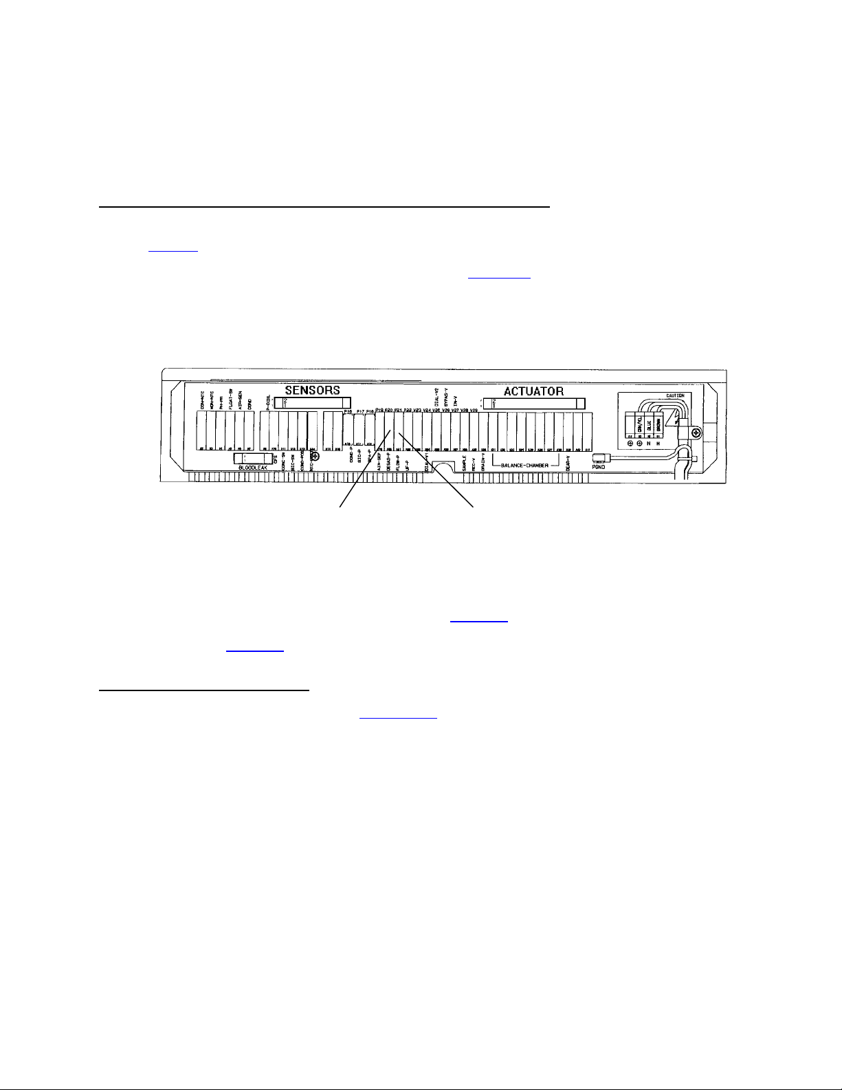
c) From VERIFY CONCENTRATE call up debug screen 9. Is PDIA still decreasing STEADILY? IGNORE UP
AND DOWN FLUCTUATIONS.
Yes Valve 37 is leaking
No Valve 35 is leaking.
BC- 2.0.0 TESTING BOTTOM VALVES ('SPENT SIDE' PRESSURIZED)
a) Remove the clamp from valve 30 and clamp the clear input tubing at the valve 24/26 JUNCTION BLOCK
(see diagram, previous page).
b) Turn the heater breaker switch off ("0" pushed down, see diagram A, page 5).
c) Plug the flow pump distribution board connector (P21, FLOW-P) into the deaeration pump's position (P20,
DEGAS-P), leaving the deaeration pump unplugged. This makes the flow pump run to pressurize 'spent
side' valves 36 and 38.
DEAER PUMP FLOW PUMP
d) Monitor PDIA for two minutes. Is it STEADILY increasing towards 10 vdc? IGNORE UP AND DOWN
FLUCTUATIONS.
Yes A leak is indicated at valve 36 or 38. See BC- 2.0.1
No See BC- 3.0.0
BC- 2.0.1 LOCATING THE LEAK
a) Clamp the clear tubing at valve 32 (see REAR VIEW diagram, page 32) and turn the power off.
b) Turn the power back on and push the SET button only ONCE. WARNING! Do NOT enter DIALYZE mode.
c) From VERIFY CONCENTRATE call up debug screen 9. Is PDIA still increasing STEADILY? IGNORE UP
AND DOWN FLUCTUATIONS.
Yes Valve 38 is leaking.
No Valve 36 is leaking.
Fresenius 2008H Troubleshooting Guide
P/N 507082 Rev. B
Page 77
Page 83

BC- 3.0.0 TESTING VALVE 32 ('SPENT SIDE' PRESSURIZED)
a) Plug valve 36 into 32's position and vica versa.
b) Monitor PDIA for two minutes. Is it STEADILY increasing towards 10 vdc? IGNORE UP AND DOWN
FLUCTUATIONS.
Yes Valve 32 is leaking.
No Plug the valves back in correctly and see BC- 3.0.1
BC- 3.0.1 TESTING VALVE 34 ('SPENT SIDE' PRESSURIZED)
a) Plug valve 38 into 34's position and vica versa.
b) Monitor PDIA for two minutes. Is it STEADILY increasing towards 10 vdc? IGNORE UP AND DOWN
FLUCTUATIONS.
Yes Valve 34 is leaking.
No Plug the valves back in correctly and see BC- 4.0.0
BC- 4.0.0 TESTING VALVE 31 ('FRESH SIDE' PRESSURIZED)
a) Remove the clamp from the valve 24/26 junction block and clamp at valve 30 again.
b) Plug the pumps back into their proper positions (P20, DEGAS-P) (P-21, FLOW-P). The deaeration pump
now runs to pressurize the 'fresh side' of the balancing chambers.
c) Plug valve 35 into 31's position (V31), and vica versa.
d) Monitor PDIA for two minutes. Is it STEADILY decreasing towards 0 vdc? IGNORE UP AND DOWN
FLUCTUATIONS.
Yes Valve 31 is leaking.
No Plug the valves back in correctly and see BC- 4.0.1
BC- 4.0.1 TESTING VALVE 33 ('FRESH SIDE' PRESSURIZED)
a) Plug valve 37 into 33's position and vica versa.
b) Monitor PDIA for two minutes. Is it STEADILY decreasing towards 0 vdc? IGNORE UP AND DOWN
FLUCTUATIONS.
Yes Valve 33 is leaking
No Plug the valves in correctly. A leak is not indicated using this test.
Page 78
Fresenius 2008H Troubleshooting Guide
P/N 507082 Rev. B
Page 84

SECTION 19 - TESTING FOR A LEAKING BALANCING CHAMBER DIAPHRAGM
This test uses BALANCING CHAMBER VOLUME CALIBRATIONS in an attempt to locate a leaking balancing
chamber (BC) diaphragm. There are two parts, collecting volumes from the fresh and spent sides of the
diaphragm. For accurate measurements use a dry 100 ml graduated cylinder for each part.
Prior to beginning assure that there are no leaking BC valves using DIAGNOSTICS/VALVE LEAK TEST.
PART I CHECKING THE FRESH SIDE
a) Loosen the drain hose from the drain port at the back of the machine (don't remove it yet).
b) Place the machine into service mode and enter CALIBRATION/BAL CHAMBER VOLUME.
c) The screen displays: BAL CHAMBER VOLUME
OPTIONAL PRIMING?
d) Push the prime button and allow it to run for 30 seconds.
e) Stop prime and push SET.
The screen displays: BAL CHAMBER VOLUME
PREPARING TO PRIME
Followed by: BAL CHAMBER VOLUME
PRIMING
Followed by: BAL CHAMBER VOLUME
PREPARING TO CALIBRAT
f) You have 25 seconds to remove the drain hose from the port and prepare to collect the fluid output from it
with the cylinder. Two cycles will be automatically dispensed. If spillage occurs start over! Collected volume
should = the value on the screen. Do NOT change screen values!! Any discrepancy (to the high side) may
indicate a leaking BC diaphragm.
Theory: The deaeration pump loads the balancing chamber with fresh dialysate at 19 psi displacing spent to
the drain (at 0 mmHg). High pressure on the fresh side of the diaphragm may result in higher volumes to the
drain if the BC diaphragm is torn.
PART II CHECKING THE SPENT SIDE
a) Connect the drain line back to the machine and push RESET to return to the main CALIBRATION menu.
b) Repeat above procedure until the message "PREPARING TO CALIBRAT" appears. You have 25 seconds
to remove red and blue hansen connectors from the shunt, put the red hansen into a bucket of water and
stand ready to collect the two-cycle output, from blue hansen, into the cylinder. If spillage should occur start
over! Collected volume should = the value on the screen. Any discrepancy (to the high side) may indicate a
leaking BC diaphragm.
Theory: The flow pump fills the balancing chamber with spent dialysate (at about 12 psi) displacing fresh into
the venous dialysate line which is now at 0 mmHg. The higher pressure on the spent side of the diaphragm
may result in higher volumes into the venous line if the diaphragm is torn.
Fresenius 2008H Troubleshooting Guide
P/N 507082 Rev. B
Page 79
Page 85

NOTES:
_____________________________________________________________________________________
_____________________________________________________________________________________
_____________________________________________________________________________________
_____________________________________________________________________________________
_____________________________________________________________________________________
_____________________________________________________________________________________
_____________________________________________________________________________________
_____________________________________________________________________________________
_____________________________________________________________________________________
_____________________________________________________________________________________
_____________________________________________________________________________________
_____________________________________________________________________________________
_____________________________________________________________________________________
_____________________________________________________________________________________
_____________________________________________________________________________________
_____________________________________________________________________________________
_____________________________________________________________________________________
_____________________________________________________________________________________
_____________________________________________________________________________________
_____________________________________________________________________________________
_____________________________________________________________________________________
_____________________________________________________________________________________
_____________________________________________________________________________________
_____________________________________________________________________________________
_____________________________________________________________________________________
_____________________________________________________________________________________
Page 80
Fresenius 2008H Troubleshooting Guide
P/N 507082 Rev. B
Page 86

NOTES:
_____________________________________________________________________________________
_____________________________________________________________________________________
_____________________________________________________________________________________
_____________________________________________________________________________________
_____________________________________________________________________________________
_____________________________________________________________________________________
_____________________________________________________________________________________
_____________________________________________________________________________________
_____________________________________________________________________________________
_____________________________________________________________________________________
_____________________________________________________________________________________
_____________________________________________________________________________________
_____________________________________________________________________________________
_____________________________________________________________________________________
_____________________________________________________________________________________
_____________________________________________________________________________________
_____________________________________________________________________________________
_____________________________________________________________________________________
_____________________________________________________________________________________
_____________________________________________________________________________________
_____________________________________________________________________________________
_____________________________________________________________________________________
_____________________________________________________________________________________
_____________________________________________________________________________________
_____________________________________________________________________________________
_____________________________________________________________________________________
Fresenius 2008H Troubleshooting Guide
P/N 507082 Rev. B
Page 81
Page 87

NOTES:
_____________________________________________________________________________________
_____________________________________________________________________________________
_____________________________________________________________________________________
_____________________________________________________________________________________
_____________________________________________________________________________________
_____________________________________________________________________________________
_____________________________________________________________________________________
_____________________________________________________________________________________
_____________________________________________________________________________________
_____________________________________________________________________________________
_____________________________________________________________________________________
_____________________________________________________________________________________
_____________________________________________________________________________________
_____________________________________________________________________________________
_____________________________________________________________________________________
_____________________________________________________________________________________
_____________________________________________________________________________________
_____________________________________________________________________________________
_____________________________________________________________________________________
_____________________________________________________________________________________
_____________________________________________________________________________________
_____________________________________________________________________________________
_____________________________________________________________________________________
_____________________________________________________________________________________
_____________________________________________________________________________________
_____________________________________________________________________________________
Page 82
Fresenius 2008H Troubleshooting Guide
P/N 507082 Rev. B
Page 88

COMMON CONVERSIONS
PRESSURE
1 Bar 29.53 inHg
1 inHg 25.4 mmHg
1 Psi 51.72 mmHg
VOLUME
1 FLUID OUNCE 26.6 MILLILITERS
1 U.S QUART 0.946 LITERS
1 U.S. GALLON 3.8 LITERS
0.034 FLUID OUNCES 1 MILLILITER
1.057 QUARTS 1 LITER
0.26 U.S. GALLON 1 LITER
MASS
1 OUNCE (avdp.) 28.35 GRAMS
1 POUND (avdp.) 0.45 KILOGRAM
0.035 OUNCE (avdp.) 1 GRAM
Page 89
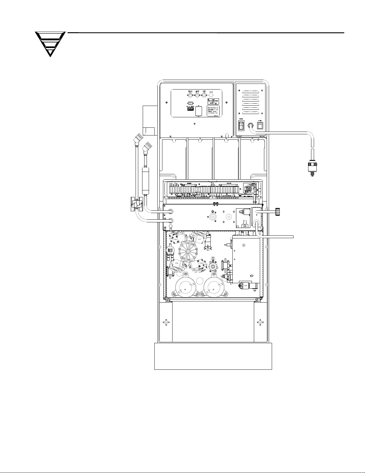
FRESENIUS USA, INC.
2637 SHADELANDS Drive
Walnut Creek, CA 94598
800 227-2572
 Loading...