


 Loading...
TNT 12000
X-Ray Test Tools
Users Manual
FBC 0003
March 2010, Rev. 2, 4/11
© 2010, 2011 Fluke Corporation. All rights reserved. Specifications are subject to change without notice. All product names are trademarks of their respective companies.
Warranty and Product Support
Fluke Biomedical, Radiation Management Services* products are warranted against defects in material and workmanship.
• Instruments: |
Warranted for one year from date of shipment. The warranty for instruments that |
|
require calibration may be extended each year by the GCL Extended Warranty |
|
Program. |
• Phantoms: |
Warranted for 6 months from date of shipment. The warranty excludes |
|
disposable phantoms. |
• CLEAR-Pb®: |
Warranted for 6 months from date of shipment against defects in material and |
|
workmanship. |
• Software: |
Warranted for 90 days that it will perform substantially in accordance with its |
|
documentation. |
• Consumables: |
Not covered under warranty. |
During the warranty period, Fluke Biomedical will, at its discretion, either repair or replace the component or product that proves to be defective upon the company’s examination. Repairs are limited to those components pertaining to functionality and not cosmetic appearance.
The limited warranty becomes void if the product is disassembled, modified or repaired by an unauthorized person or facility, or if the product’s functionality is impaired by damage, abuse or failure to use and maintain the instrument according to the manufacturer’s instructions.
To exercise this warranty, the owner must write or call a Fluke Biomedical customer service representative to receive a Service Return Authorization (SRA). The owner must send the product, transportation prepaid, to a specified service facility. Repairs will then be made, and the product will be returned to the owner with transportation (normal, service) prepaid. Repaired or replaced products are warranted for the balance of the warranty period. For products not covered by warranty, the part repaired has a warranty of 90 days.
Warranty Limitations: There are no warranties expressed or implied, including without limitation any implied warranty of merchantability of fitness, which extend beyond that discretion of the face hereof. This express warranty excludes coverage of and does not provide relief for incidental or consequential damages of any kind or nature, including but not limited to loss of use, loss of sales or inconvenience. This exclusive remedy of the purchaser is limited to repair, recalibration or replacement of the instrument at the Company’s discretion.
Disclaimer
Please Note: If an instrument is intended for the detection and measurement of ionizing radiation, it should be used only by persons who have been trained in the appropriate safety procedures to be followed in the presence of radiation and the proper interpretation of the instrument’s readings. Instruction and precautions contained in the manuals must be read before use and strictly followed. Failure to follow these instructions and precautions may result in inaccurate readings and/or user hazard. Battery and other preoperational checks should be performed prior to each use to assure that the instrument is functioning properly.
* Includes products branded Nuclear Associates and Victoreen®. ©

Notices
All Rights Reserved
Copyright 2008, Fluke Biomedical. No part of this publication may be reproduced, transmitted, transcribed, stored in a retrieval system, or translated into any language without the written permission of Fluke Biomedical.
Copyright Release
Fluke Biomedical agrees to a limited copyright release that allows you to reproduce manuals and other printed materials for use in service training programs and other technical publications. If you would like other reproductions or distributions, submit a written request to Fluke Biomedical.
Unpacking and Inspection
Follow standard receiving practices upon receipt of the instrument. Check the shipping carton for damage. If damage is found, stop unpacking the instrument. Notify the carrier and ask for an agent to be present while the instrument is unpacked. There are no special unpacking instructions, but be careful not to damage the instrument when unpacking it. Inspect the instrument for physical damage such as bent or broken parts, dents, or scratches.
Technical Support
For application support or answers to technical questions, either email radtechsupport@flukebiomedical.com or call 1-800- 850-4608 or 1-440-498-2560. Technical support is also available at http://www.flukebiomedical.com/techsupport.
Claims
Our routine method of shipment is via common carrier, FOB origin. Upon delivery, if physical damage is found, retain all packing materials in their original condition and contact the carrier immediately to file a claim. If the instrument is delivered in good physical condition but does not operate within specifications, or if there are any other problems not caused by shipping damage, please contact Fluke Biomedical or your local sales representative.
Standard Terms and Conditions
Refunds and Credits
Please note that only serialized products and their accessory items (i.e., products and items bearing a distinct serial number tag) are eligible for partial refund and/or credit. Nonserialized parts and accessory items (e.g., cables, carrying cases, auxiliary modules, etc.) are not eligible for return or refund. Only products returned within 90 days from the date of original purchase are eligible for refund/credit. In order to receive a partial refund/credit of a product purchase price on a serialized product, the product must not have been damaged by the customer or by the carrier chosen by the customer to return the goods, and the product must be returned complete (meaning with all manuals, cables, accessories, etc.) and in “as new” and resalable condition. Products not returned within 90 days of purchase, or products which are not in “as new” and resalable condition, are not eligible for credit return and will be returned to the customer. The Return Procedure (see below) must be followed to assure prompt refund/credit.
Restocking Charges
Products returned within 30 days of original purchase are subject to a minimum restocking fee of 25 %. Products returned in excess of 30 days after purchase, but prior to 90 days, are subject to management approval. Additional charges for damage and/or missing parts and accessories will be applied to all returns.
Return Procedure
All items being returned (including all warranty-claim shipments) must be sent freight-prepaid to our factory location. When you return an instrument to Fluke Biomedical, we recommend using United Parcel Service, Federal Express, or Air Parcel Post. We also recommend that you insure your shipment for its actual replacement cost. Fluke Biomedical will not be responsible for lost shipments or instruments that are received in damaged condition due to improper packaging or handling.
Use the original carton and packaging material for shipment. If they are not available, we recommend the following guide for repackaging:
Use a double-walled carton of sufficient strength for the weight being shipped.
Use heavy paper or cardboard to protect all instrument surfaces. Use nonabrasive material around all projecting parts.
Use at least four inches of tightly packed, industry-approved, shock-absorbent material around the instrument.
Returns for partial refund/credit:
Every product returned for refund/credit must be accompanied by a Return Material Authorization (RMA) number, obtained from our Customer Support Group at 1-800-850-4608 or 1-440-498-2564 or email orders@flukebiomedical.com.

Repair and calibration:
To find the nearest service center, go to www.flukebiomedical.com/service, or
In the U.S.A.:
Cleveland Calibration Lab
Tel: 1-800-850-4606 ext. 2564
Email: globalcal@flukebiomedical.com
Everett Calibration Lab
Tel: 1-888-993-5853
Email: service.status@fluke.com
In Europe:
Eindhoven Calibration Lab
Tel: +31-402-675300
Email: ServiceDesk@fluke.com
Certification
This instrument was thoroughly tested and inspected. It was found to meet Fluke Biomedical’s manufacturing specifications when it was shipped from the factory. Calibration measurements are traceable to the National Institute of Standards and Technology (NIST). Devices for which there are no NIST calibration standards are measured against in-house performance standards using accepted test procedures.
WARNING
Unauthorized user modifications or application beyond the published specifications may result in electrical shock hazards or improper operation. Fluke Biomedical will not be responsible for any injuries sustained due to unauthorized equipment modifications.
Restrictions and Liabilities
Information in this document is subject to change and does not represent a commitment by Fluke Biomedical. Changes made to the information in this document will be incorporated in new editions of the publication. No responsibility is assumed by Fluke Biomedical for the use or reliability of software or equipment that is not supplied by Fluke Biomedical, or by its affiliated dealers.
Manufacturing Location
The TNT 12000 X-Ray Test device is manufactured in Cleveland, Ohio by Fluke Biomedical, 6045 Cochran Rd., Cleveland, OH, U.S.A.
Table of Contents
Chapter |
Title |
Page |
1 |
Introduction ......................................................................................... |
1-1 |
|
Introduction........................................................................................................ |
1-3 |
|
Unpacking and Inspection.................................................................................. |
1-3 |
|
Storage ............................................................................................................... |
1-3 |
|
General Safety Considerations........................................................................... |
1-3 |
|
Symbols ............................................................................................................. |
1-4 |
|
RF Certification ................................................................................................. |
1-4 |
|
United States.................................................................................................. |
1-5 |
|
Canada ........................................................................................................... |
1-5 |
|
Europe ........................................................................................................... |
1-5 |
|
Japan.............................................................................................................. |
1-5 |
|
Familiarization................................................................................................... |
1-6 |
|
How to Charge the Battery ................................................................................ |
1-9 |
|
Accessories ........................................................................................................ |
1-10 |
|
Specifications..................................................................................................... |
1-11 |
2 |
Operation ............................................................................................. |
2-1 |
|
Introduction........................................................................................................ |
2-3 |
|
Safety Information ............................................................................................. |
2-3 |
|
How to Set Up the System................................................................................. |
2-3 |
|
Display to Detector Communications............................................................ |
2-3 |
|
How to Setup a Wireless Connection........................................................ |
2-4 |
|
How to Setup a USB Connection.............................................................. |
2-4 |
|
Multiple Detector Connections ................................................................. |
2-4 |
|
Communication Settings ........................................................................... |
2-4 |
|
How to Use the X-ray Detector (TNT 12000WD) ............................................ |
2-5 |
|
How to Position the X-ray Detector .............................................................. |
2-6 |
|
Detector Placement with Above Table X-ray Source ............................... |
2-6 |
|
Detector Placement with Below Table X-ray Source ............................... |
2-7 |
|
How to Measure X-ray Parameters ............................................................... |
2-7 |
|
X-ray Display Configuration..................................................................... |
2-8 |
|
Measurement Mode Setup......................................................................... |
2-9 |
|
Measurement Mode Profile Parameters .................................................... |
2-9 |
|
How to Set a Detector Profile ................................................................... |
2-10 |
i

TNT 12000
Users Manual
|
Auto Profiles.................................................................................................. |
2-11 |
|
Default Profiles.............................................................................................. |
2-11 |
|
How to Change Profile Parameters ............................................................... |
2-12 |
|
How to Make a User-Defined Profile............................................................ |
2-13 |
|
How to Enter a Delay .................................................................................... |
2-15 |
|
How to Use the Dosimeter Detector (TNT 12000 DoseMate) .......................... |
2-15 |
|
Ion Chamber Selection and Setup ................................................................. |
2-16 |
|
Ion Chamber Connection and Placement ...................................................... |
2-16 |
|
How to Place the Ion Chamber for Over-Table X-ray Sources ................ |
2-17 |
|
How to Place the Ion Chamber for Under-Table X-ray Sources .............. |
2-20 |
|
How to Place the Ion Chamber for Horizontal X-ray Beams.................... |
2-22 |
|
How to Place the Ion Chamber in Limited Access Situations .................. |
2-23 |
|
How to Make a Dosimeter Measurement ...................................................... |
2-24 |
|
Ion Chamber Setup.................................................................................... |
2-24 |
|
Dosimeter Measurements.......................................................................... |
2-26 |
|
How to Add an Ion Chamber Definition or Cal Factor............................. |
2-26 |
|
How to Edit an Ion Chamber Definition or Cal Factor ............................. |
2-29 |
|
How to Delete an Ion Chamber Definition or Cal Factor ......................... |
2-30 |
|
Measurement Mode Selection................................................................... |
2-31 |
|
How to Set Units of Measurement ............................................................ |
2-32 |
|
Air Density Correction.............................................................................. |
2-34 |
|
How to Adjust the Internal Temperature/Pressure Sensor ........................ |
2-36 |
|
Dosimeter Status ....................................................................................... |
2-37 |
|
How to Use the mAs Detector (TNT 12000 mAs) ............................................ |
2-38 |
|
How to Connect to the X-ray Tube for mAs Measurements ......................... |
2-39 |
|
Shunt Connections .................................................................................... |
2-40 |
|
Clamp Connections ................................................................................... |
2-43 |
|
How to Measure mAs.................................................................................... |
2-43 |
|
Setup Options..................................................................................................... |
2-44 |
|
Connection Option......................................................................................... |
2-45 |
|
How to Set Power Settings ............................................................................ |
2-45 |
|
Detector Battery Charge Level.................................................................. |
2-46 |
|
Display Off Time ...................................................................................... |
2-46 |
|
Low Power Time....................................................................................... |
2-46 |
|
System Off Time ....................................................................................... |
2-47 |
|
Brightness.................................................................................................. |
2-47 |
|
How to Set the Date and Time....................................................................... |
2-47 |
3 |
Microsoft Excel Add-In Software ....................................................... |
3-1 |
|
Introduction........................................................................................................ |
3-3 |
|
System Requirements ........................................................................................ |
3-3 |
|
How to Install the Add-In .................................................................................. |
3-3 |
|
How to Install the Excel Add-In Software .................................................... |
3-3 |
|
How to Install the TNT 12000 Vendor Class Driver..................................... |
3-4 |
|
How to Uninstall the Add-In.............................................................................. |
3-5 |
|
How to Uninstall the Excel Add-In Software................................................ |
3-5 |
|
How to Uninstall the TNT 12000 Vendor Class Driver ................................ |
3-6 |
|
Communication between a PC and Detector ..................................................... |
3-7 |
|
How Initialize the TNT 12000 Add-In Software ............................................... |
3-8 |
|
TNT 12000WD Toolbar Options....................................................................... |
3-9 |
|
DoseMate Toolbar Options................................................................................ |
3-11 |
|
mAs Toolbar Options......................................................................................... |
3-13 |
ii

Contents (continued)
4 |
Maintenance......................................................................................... |
4-1 |
|
|
Introduction........................................................................................................ |
4-3 |
|
|
Ion Chamber Care.............................................................................................. |
4-3 |
|
|
Cleaning............................................................................................................. |
4-3 |
|
|
Firmware Upgrade ............................................................................................. |
4-3 |
|
|
|
Detector ......................................................................................................... |
4-3 |
|
|
Display........................................................................................................... |
4-4 |
|
Service and Calibration...................................................................................... |
4-4 |
|
|
|
Packing .......................................................................................................... |
4-4 |
|
|
Shipping......................................................................................................... |
4-4 |
Appendices |
|
||
|
A |
Model 96020C Ion Chamber....................................................................... |
A-1 |
|
B |
Model 96035B Ion Chamber....................................................................... |
B-1 |
|
C |
Model 500-100 CT Probe............................................................................ |
C-1 |
|
D |
Model 500-200 CT Probe............................................................................ |
D-1 |
|
E |
TNT 12000WD kVp, Exposure, and Exposure Time Measurement........... |
E-1 |
|
F |
Warnings and Error Messages..................................................................... |
F-1 |
|
G |
Troubleshooting .......................................................................................... |
G-1 |
|
H |
PTB Information ......................................................................................... |
H-1 |
iii

TNT 12000
Users Manual
iv
List of Tables
Table |
Title |
Page |
1-1. |
Symbols.................................................................................................................. |
1-4 |
1-2. |
Display Components .............................................................................................. |
1-6 |
1-3. |
X-ray Detector Components................................................................................... |
1-7 |
1-4. |
Dose Detector Components.................................................................................... |
1-8 |
1-5. |
Battery Status Indicator.......................................................................................... |
1-10 |
1-6. |
Accessories............................................................................................................. |
1-10 |
1-7. |
Optional Accessories.............................................................................................. |
1-11 |
2-1. |
Communication Status Indicator............................................................................ |
2-3 |
2-2. |
Settable Profile Parameters .................................................................................... |
2-9 |
2-3. Default Parameter Values for Each Measurement Mode....................................... |
2-12 |
|
2-4. |
Cal Factor Units ..................................................................................................... |
2-29 |
2-5. |
Dosimeter Measurement Modes............................................................................. |
2-31 |
2-6. |
Dose Rate Values ................................................................................................... |
2-33 |
2-7. |
mAs Current Ranges .............................................................................................. |
2-39 |
3-1. TNT 12000WD Excel Add-In Menu and Toolbar Options ................................... |
3-10 |
|
3-2. DoseMate Excel Add-In Menu and Toolbar Options ............................................ |
3-12 |
|
3-3. |
mAs Excel Add-In Menu and Toolbar Options ..................................................... |
3-14 |
v

TNT 12000
Users Manual
vi
List of Figures
Figure |
Title |
Page |
1-1. |
Charging Methods.................................................................................................. |
1-9 |
2-1. |
Wired (USB) Connection....................................................................................... |
2-4 |
2-2. |
Connection Screen ................................................................................................. |
2-5 |
2-3. |
X-ray Detector Alignment Marks .......................................................................... |
2-6 |
2-4. |
X-ray Detector Setup for Above Table X-ray Source............................................ |
2-6 |
2-5. |
X-ray Detector Setup for Below Table X-ray Source ............................................ |
2-7 |
2-6. |
X-ray Detector Measurement Screen ..................................................................... |
2-8 |
2-7. |
Mode Setup Screen ................................................................................................ |
2-9 |
2-8. |
Ion Chamber Connection to Dosimeter.................................................................. |
2-17 |
2-9. |
Test Stand Configuration for Over-Table Tubes.................................................... |
2-18 |
2-10. |
Test Stand Configuration for Under-Table X-ray Tube......................................... |
2-20 |
2-11. |
Test Stand Configuration for Horizontal Tube....................................................... |
2-22 |
2-12. |
Ion Chamber Cable Stem ....................................................................................... |
2-23 |
2-13. |
Ion Chamber Notification Screen........................................................................... |
2-24 |
2-14. |
Ion Chamber Setup Screen..................................................................................... |
2-25 |
2-15. |
Dosimeter Measurement Screen............................................................................. |
2-26 |
2-16. |
mAs Measurement Option Screen.......................................................................... |
2-38 |
2-17. |
Shunt or Clamp Screen........................................................................................... |
2-39 |
2-18. |
Direct mAs Shunt Connection to Current Jacks..................................................... |
2-41 |
2-19. |
mAs Test Leads Connection .................................................................................. |
2-42 |
2-20. |
mAs Measurement Screen...................................................................................... |
2-43 |
2-21. |
Setup Screen........................................................................................................... |
2-44 |
2-22. |
Setup Screen from mAs Measurement................................................................... |
2-44 |
2-23. |
Setup Screen with mAs and DoseMater Detectors Connected .............................. |
2-45 |
2-24. |
Power Setting Screen ............................................................................................. |
2-45 |
2-25. |
Sleep Mode Display ............................................................................................... |
2-46 |
2-26. |
Date and Time Setting Screen................................................................................ |
2-47 |
3-1. |
InstallShield Wizard............................................................................................... |
3-3 |
3-2. |
USB Connection between PC and Detector........................................................... |
3-4 |
3-3. |
Found New Hardware Wizard Window................................................................. |
3-5 |
3-4. |
Add or Remove Programs Dialog .......................................................................... |
3-6 |
3-5. |
Computer Management Windows.......................................................................... |
3-7 |
3-6. |
USB Connection between PC and Detector........................................................... |
3-7 |
3-7. |
Wireless Connection Between PC and Detector .................................................... |
3-8 |
3-8. |
Detector Connection Window................................................................................ |
3-9 |
vii

TNT 12000
Users Manual
3-9. |
TNT 12000WD Excel Add-In Menu and Toolbar (Excel 2007) ........................... |
3-10 |
3-10. |
TNT 12000WD Excel Add-In Menu and Toolbar (Excel 2003) ........................... |
3-11 |
3-11. |
DoseMate Excel Add-In Menu and Toolbar (Excel 2007) .................................... |
3-11 |
3-12. |
DoseMate Excel Add-In Menu and Toolbar (Excel 2003) .................................... |
3-13 |
3-13. |
mAs Excel Add-In Menu and Toolbar (Excel 2007) ............................................. |
3-13 |
3-14. |
mAs Excel Add-In Menu and Toolbar (Excel 2003) ............................................. |
3-14 |
viii
Chapter 1
Introduction
Title |
Page |
Introduction.......................................................................................................... |
1-3 |
Unpacking and Inspection.................................................................................... |
1-3 |
Storage ................................................................................................................. |
1-3 |
General Safety Considerations............................................................................. |
1-3 |
Symbols ............................................................................................................... |
1-4 |
RF Certification ................................................................................................... |
1-4 |
United States.................................................................................................... |
1-5 |
Canada ............................................................................................................. |
1-5 |
Europe ............................................................................................................. |
1-5 |
Japan................................................................................................................ |
1-5 |
Familiarization..................................................................................................... |
1-6 |
How to Charge the Battery .................................................................................. |
1-9 |
Accessories .......................................................................................................... |
1-10 |
Specifications....................................................................................................... |
1-11 |
1-1

TNT 12000
Users Manual
1-2

Introduction 1
Introduction
Introduction
The Fluke Biomedical TNT 12000 X-ray Test Tools (the TNT 12000) are used to calibrate and service diagnostic X-ray imaging systems.
The TNT 12000 X-ray Test Tools has these parts:
•TNT 12000WD X-ray Detector option (the X-ray Detector). The X-ray Detector contains an array of solid-state sensors and filters that measure kV, Dose, Half-Value Layer (HVL), and exposure time.
•TNT 12000 DoseMate option (the Dosimeter Detector). With its related ion chambers, the Dosimeter Detector measures dose and rate on all X-ray modalities: radiographic, mammographic, dental, cine, fluoroscopic, and CT.
•TNT 12000 mAs option (the mAs Detector) to measure X-ray tube current over time. Use the mAs Detector on radiographic (or Dental or Mammography) and fluoroscopic X-ray imaging modalities. The mAs option is installed in the X-ray or Dosimeter Detectors.
•TNT 12000 Display (the Display). The Display contains a 320 x 240 color LCD, four navigation buttons, an ENTER button, and a power button. The display controls testsystem functions and shows all system measurements.
•TNT 12000/DoseMate/mAs CD that contains an Excel Add-in to control the test system and import all measurements.
•AC Power Adapter used to charge the rechargeable batteries in the X-ray Detector, Dosimeter Detector, mAs Detector, and the Display.
The TNT 12000 options communicate between the detectors and the display or computer through a wireless (ZigBee) or wired (USB) connection.
Unpacking and Inspection
The TNT 12000 is shipped in a container designed to prevent damage during shipment. Examine the components for damage, and immediately report any damage to the shipper. Keep the damaged shipping container and packing material for inspection by the carrier.
Note
The shipping container contains foam inserts to prevent damage during shipment. Keep these and the container for future shipment.
When you unpack the TNT 12000, compare the parts to the packing list. If you ordered the mAs option, make sure it is installed in a Detector by looking for an mAs input jack on a Detector. See the Familiarization section later in this chapter. Report any shortage to the place of purchase.
Storage
To store the TNT 12000, put it in its carrying case. Keep it in an environment free of corrosive material and within the storage temperature and operating humidity ranges shown in the specifications. Also prevent vibration and shock to the system.
General Safety Considerations
In this manual, a Warning identifies conditions and actions that pose hazards to the user. A Caution identifies conditions and actions that may damage the test equipment or the equipment under test.
Symbols used on the test system or in this manual are explained in Table 1-1.
1-3

TNT 12000
Users Manual
To ensure safe operation of the Test System, fully observe all instructions and warnings contained in this manual.
XW Warning
To avoid possible electrical shock or personal injury, follow these guidelines:
•Use the TNT 12000 only in the manner specified by the manufacturer.
•Do not use the product if it operates abnormally.
•Use only the ac adapter provided with the system.
•Ensure that the external power source is properly rated for the system.
W Caution
To avoid damage to the TNT 12000 or adverse affects on its performance, follow these guidelines:
•Allow only qualified technical personnel to service the system.
•
•
Do not expose the system to temperature extremes. Ambient temperatures should remain between 0 °C and 35 °C. System performance may be adversely affected if temperatures fluctuate above or below this range.
Clean the TNT 12000 by gently wiping down with a clean, lint-free cloth dampened with a mild detergent solution. Do not immerse the unit in liquid.
Symbols
Table 1-1 describes the symbols associated with the TNT 12000.
Table 1-1. Symbols
Symbol |
Description |
Symbol |
Description |
|
|
|
|
X |
Hazardous voltage |
P |
Conforms to European Union directives |
|
|
|
|
W |
Important information, refer to manual |
; |
Conforms to relevant Australian EMC |
requirements |
|||
|
|
|
|
• |
Complies with RoHS directives |
Ž |
Complies with Part 15 of the FCC rules |
|
|
|
|
|
|
|
This product contains a Lithium-ion |
|
Do not dispose of this product as |
|
battery. Do not mix with solid waste |
|
|
stream. Spent batteries should be |
|
|
unsorted municipal waste. Go to |
´ |
|
~ |
disposed of by a qualified recycler or |
||
|
Fluke’s website for recycling |
|
hazardous materials handler per local |
|
information. |
|
|
|
|
regulations. Contact your authorized Fluke |
|
|
|
|
|
|
|
|
Service Center for recycling information. |
|
|
|
|
RF Certification
The TNT 12000 contains radio transceivers that are used for wireless communication between the Display and the Detectors. The transceivers operate in the 2.4 GHz frequency band with a maximum transmitting power of 1 mW. The transceivers have been tested and certified for use in various areas worldwide.
1-4

Introduction 1
RF Certification
United States
The transceivers used in the TNT 12000 have been approved for use in the United States by FCC Part 15 certification, FCC ID: OUR-XBEE. The following statement accompanies the device:
“Contains FCC ID: OUR-XBEE"
The enclosed device complies with Part 15 of the FCC rules. Operation is subject to the following two conditions: (1) this device may not cause harmful interference and (2) this device must accept any interference received, including interference that may cause undesired operation.
This equipment has been tested and found to comply with the limits for a Class A digital device, pursuant to Part 15 of the FCC Rules. These limits are designed to provide reasonable protection against harmful interference in a commercial environment. This equipment generates, uses, and can radiate radio frequency energy and, if not installed and used in accordance with the instructions, may cause harmful interference to radio communications. However, there is no guarantee that interference will not occur in a particular installation.
If this equipment does cause harmful interference to radio or television reception, which can be determined by turning the equipment off and on, the user is encouraged to try to correct the interference by one or more of the following measures: Re-orient or relocate the receiving antenna, increase the separation between the equipment and receiver, connect equipment and receiver to outlets on different circuits, or consult the dealer or an experienced radio/television technician for help.
W Warning
To satisfy FCC RF exposure requirements for mobile transmitting devices, a separation distance of 20 cm or more should be maintained between the antenna of this device and persons during device operation. To ensure compliance, operations at closer than this distance is not recommended. The antenna used for this transmitter must not be co-located in conjunction with any other antenna or transmitter.
Canada
The transceiver used in the TNT 12000 has been certified for use in Canada, IC certification number IC: 4214A-XBEE.
Europe
The transceiver used in the TNT 12000 conforms to European Union EMC Directive 2004/108/EC, ETSI EN 301 489-1 and EN 301 489-17; and R&TTE Directive 1999/5/EC, ETSI EN300 328.
Japan
Japan ID: 005NYCA0378
1-5
TNT 12000
Users Manual
Familiarization
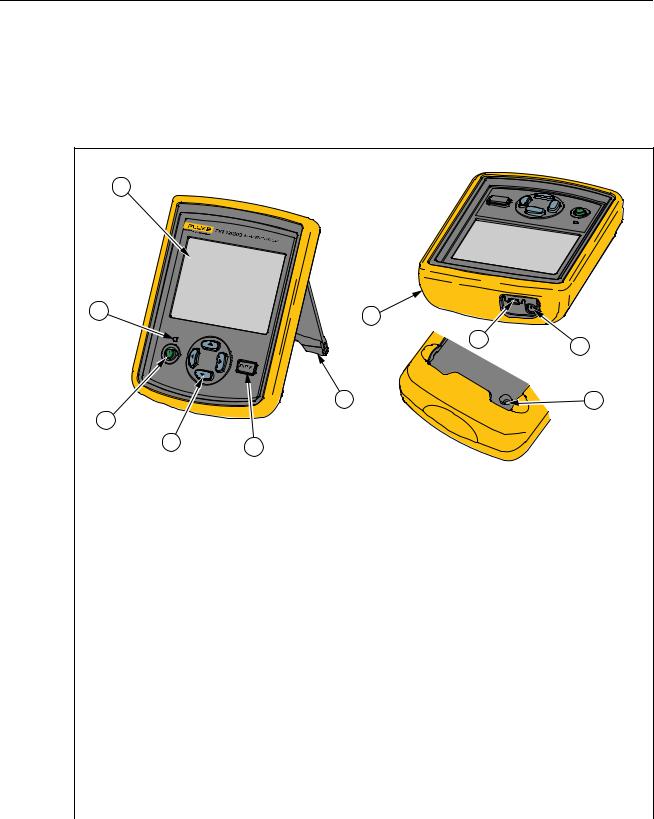
To use the TNT 12000, you must first connect the Display to the X-ray Detector or Dosimeter Detector. Tables 1-2 through 1-4 shows the controls, indicators, and connectors of the Display and Detectors.
Table 1-2. Display Components
1 |
2 |
7 |
|
3 |
6 |
4 |
5 |
|
8 |
RESET
9 |
10 |
fct02.eps
Item |
Name |
Description |
|
|
|
A |
LCD Panel |
320X240 color display |
|
|
|
B |
Battery-status Indicator |
Tri color LED indicating the battery status of the display. |
|
|
Refer to the Battery Charging section for more details. |
C |
On/Off Switch |
Powers the display On/Off |
|
|
|
D |
Navigational Keys: |
Moves the cursor through the menu options on the display |
|
Left, Right, Up, and Down keys |
screen in various directions. |
|
Note: The cursor movement is circular |
|
|
|
|
|
|
|
E |
Enter key |
Selects the menu option on the display screen |
|
|
|
F |
Stand |
Display support stand |
|
|
|
G |
Holster |
Protective cover for the display |
|
|
|
H |
USB Connector |
To connect the detector or a Computer via USB cable |
|
|
|
I |
AC adapter connector |
Connects the ac adapter |
|
|
|
J |
Reset switch |
Resets the display |
|
|
|
|
|
Note |
A short beep sounds for a valid key press, and a long beep sounds for an invalid key press.
1-6

Introduction 1
Familiarization
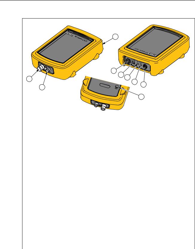
Table 1-3. X-ray Detector Components
1 |
3 |
|
|
4 |
|
|
5 |
2 |
|
6 |
|
|
7 |
mAs Option |
|
8 |
|
|
|
Installed |
|
|
|
|
9 |
10 |
|
|
|
2 |
|
|
|
fct01.eps |
Item |
Name |
Description |
A |
Exposure Surface |
The surface to be exposed to x-ray radiation |
B |
Threaded Insert |
Secures the detector to a test stand, such as a |
|
|
camera tripod |
C |
Holster |
Protective cover for the display |
|
|
|
D |
AC adapter connector |
Connects the ac adapter |
|
|
|
E |
USB Connector |
To connect the detector or a Computer via USB |
|
|
cable |
F |
Communication status LED |
Indicates the communication status (see the |
|
|
Display to Detector Communications section in |
|
|
Chapter 1) |
G |
Battery-status Indicator |
Tri color LED indicating the battery status of the |
|
|
display. Refer to the Battery Charging section |
|
|
for more details. |
|
|
|
H |
On/Off Switch |
Powers the Detector On/Off |
|
|
|
I |
Reset switch |
Resets the Detector |
|
|
|
J |
mAs input jack (when mAs option is |
Male coaxial BNC jack for connection to the |
|
installed) |
mA/mAs interface cable |
WCaution
To avoid damage to the Detector, never connect to generator mA/mAs taps without the TNT 12000 mAs shunt.
1-7
TNT 12000
Users Manual
Table 1-4. Dose Detector Components
1 |
2 |
3 |
4
5
6
7 |
8 |
9
|
|
fct11.eps |
|
|
|
Item |
Name |
Description |
|
|
|
A |
mAs input jack (when mAs option is installed) |
Male coaxial BNC jack for connection to the |
|
|
mA/mAs interface cable |
|
|
WCaution |
|
|
To avoid damage to the Detector, |
|
|
never connect to generator |
|
|
mA/mAs taps without the TNT |
|
|
12000 mAs shunt. |
|
|
|
B |
Ion Chamber Connector |
Triaxial input connection for the Ion Chamber. |
|
|
|
C |
Holster |
Protective cover for Dosimeter |
|
|
|
D |
AC adapter connector |
Connects the ac adapter |
|
|
|
E |
USB Connector |
To connect the Detector or a computer via |
|
|
USB cable |
F |
Communications Status Indicator |
Indicates the communication status (see the |
|
|
Display to Detector Communications section |
|
|
in Chapter 1) |
G |
Battery-status Indicator |
Tri color LED indicating the battery status of |
|
|
the display. Refer to the Battery Charging |
|
|
section for more details. |
|
|
|
H |
On/Off Switch |
Powers the Detector On and Off. |
|
|
|
I |
Reset switch |
Resets the Dose Detector |
|
|
|
1-8
Introduction 1
How to Charge the Battery
How to Charge the Battery
Charging the internal batteries of the detectors and display from mains power can be done in three different configurations as shown in Figure 1-1.
WCaution
To prevent damage to the TNT 12000, do not leave batteries unused for an extended period of time. When a battery has not been used for six months, check the charge status and charge if necessary.
Power Source |
Computer to Power Source |
Detector to Display to Power Source |
|
OR |
|
OR |
|
|
|
|
fct10.eps |
Figure 1-1. Charging Methods
To charge a Detector or the Display directly from mains power, connect the ac-power adapter directly to the ac adapter connector on a Detector or the Display. To charge a Detector and the Display simultaneously, connect the ac adapter to the ac adapter connection on the Display and then, using the Mini-B to Type-A USB cable, connect the Detector to the Display.
Note
See the markings on the ends of the cable to identify the Mini-A and Mini-B ends.
A Detector or Display battery can also be charged through a USB connector on a PC. Connect the Display or Detector to a PC USB port using the Mini-A to Type-A USB cable.
Both Detectors and the Display have a battery-status indicator to indicate the condition of the internal battery. The indicator is a tri-color LED that shows the level of charge on the internal battery. Table 1-5 explains the battery-status indicator levels.
1-9

TNT 12000
Users Manual
|
Table 1-5. Battery Status Indicator |
|
|
Color |
Description |
|
|
Blue |
Battery is fully charged. |
|
|
Green |
Battery is charging. |
|
|
Off |
Unit is not connected to a charging power source and is operating on battery power. |
|
|
Yellow |
Battery is approximately 20 % charged. |
|
|
Red |
Battery has 10 % charge and will turn off in two minutes. |
|
|
Accessories
Items shown in Table 1-6 are standard accessories provided with the TNT 12000. Some accessories are only associated with specific options. Items in Table 1-7 are optional.
Contact your Fluke Biomedical representative to purchase the accessories shown below.
Table 1-6. Accessories |
|
|
|
|
|
Accessory |
|
Fluke Biomedical Part No |
|
|
|
Cable, Type A to Mini B USB |
|
3346027 |
|
|
|
Cable, Mini A to Mini B USB |
|
3346030 |
|
|
|
ZigBee Dongle |
|
3341333 |
|
|
|
AC Power Adapter |
|
3548014 |
|
|
|
Multi-Prong Adapter |
|
3549414 |
|
|
|
CD, TNT 12000/DoseMate/mAs |
|
3586667 |
|
|
|
Ansur Demo CD |
|
2795488 |
|
|
|
DoseMate Option |
|
|
|
|
|
Carrying Case, DoseMate/mAs |
|
3586528 |
|
|
|
Test Stand, DoseMate |
|
3586537 |
|
|
|
HVL Filter Set |
|
3264115 |
|
|
|
Adapter Stem |
|
3264091 |
|
|
|
Tirax Cable, Male to Male, BNC, 1.82 m (6 ft) |
|
3586644 |
|
|
|
mAs Option |
|
|
|
|
|
mA Cable Assembly, BNC (male to female) |
|
1918780 |
|
|
|
mA Shunt Assembly |
|
3586555 |
|
|
|
Alligator Clip, Banana Plug (Red) |
|
1942964 |
|
|
|
Alligator Clip, Banana Plug (Black) |
|
1942920 |
|
|
|
Connector, BNC (F) to Binding Posts |
|
1938315 |
|
|
|
Connector, BNC (F) to Double Banana Plug |
|
1633042 |
|
|
|
1-10
|
|
|
|
Introduction |
1 |
|
|
|
|
|
Specifications |
||
|
Table 1-7. Optional Accessories |
|
|
|
||
|
|
|
|
|
|
|
|
Accessory |
|
Fluke Biomedical Part No |
|
|
|
|
|
|
|
|
|
|
|
Ansur Plug In, TNT 12000 |
|
|
3337356 |
|
|
|
|
|
|
|
|
|
|
Optional Accessories for the DoseMate Option |
|
|
|
||
|
|
|
|
|
|
|
|
Diagnostic Ionization Chamber, 150cc, Model 96020C |
|
2549992 |
|
|
|
|
|
|
|
|
|
|
|
Diagnostic Ionization Chamber, 15cc, Model 96035B |
|
2550024 |
|
|
|
|
|
|
|
|
|
|
|
CT Ion Chamber, 3cc, Model 500-100 |
|
|
2549734 |
|
|
|
|
|
|
|
|
|
|
CT Ion Chamber, 10cc, Model 500-200 |
|
|
2549741 |
|
|
|
|
|
|
|
|
|
|
Triax Cable, Male to Male, BNC, 6.1 m (20 ft) |
|
3265786 |
|
|
|
|
|
|
|
|
|
|
|
Optional Accessories for the mAs Option |
|
|
|
||
|
|
|
|
|
|
|
|
Non-Invasive mA/mAs Clamp |
|
|
3586746 |
|
|
|
|
|
|
|
|
|
|
mA Cable Assembly, BNC, 6.1 m (20 ft) (male to female) |
|
2118136 |
|
|
|
|
|
|
|
|
|
|
|
Specifications |
|
|
|
|
|
|
Physical |
|
|
|
|
|
|
Display Screen........................................................ |
320X240 Color LCD |
|
|
|
|
|
Size |
|
|
|
|
|
|
Display ................................................................ |
15.24 cm X 11.43 cm X 4.45 cm (6 in X 4.5 in X 1.75 in) |
|
|||
|
Detector .............................................................. |
15.24 cm X 11.43 cm X 4.45 cm (6 in X 4.5 in X 1.75 in) |
|
|||
|
Weight |
|
|
|
|
|
|
Display ................................................................ |
347 g (0.93 lb) |
|
|
|
|
|
X-ray Detector w/o mAs...................................... |
560 g (1.5 lb) |
|
|
|
|
|
X-ray Detector with mAs ..................................... |
560 g (1.5 lb) |
|
|
|
|
|
DoseMate w/o mAs............................................. |
392 g (1.05 lb) |
|
|
|
|
|
DoseMate with mAs............................................ |
392 g (1.05 lb) |
|
|
|
|
|
Electrical |
|
|
|
|
|
|
Battery |
|
|
|
|
|
|
Battery Type ....................................................... |
Lithium-Ion, 3.7 V, 4000 mAh |
|
|
|
|
|
Battery Charging time ......................................... |
Approx. 5 hr |
|
|
|
|
|
Battery Discharge time ....................................... |
Approx. 8 hr |
|
|
|
|
|
Battery Cutoff Voltage......................................... |
3.0 V |
|
|
|
|
|
AC Adapter |
|
|
|
|
|
|
Input Voltage....................................................... |
100 V ac to 240 V ac |
|
|
|
|
|
Input Frequency.................................................. |
50/60 Hz |
|
|
|
|
|
Input Current....................................................... |
0.5 A (rms) |
|
|
|
|
|
Output Voltage.................................................... |
+6 V dc |
|
|
|
|
|
Output Current .................................................... |
2500 mA (max.) |
|
|
|
|
1-11

TNT 12000
Users Manual
Environmental
Operating Temperature........................................... |
0 °C to 35 °C (32 °F to 95 °F) |
Storage Temperature.............................................. |
-35 °C to 50 °C (-31 °F to +122 °F) |
Operating Humidity ................................................. |
20 % to 80 % RH (Non Condensing) |
Wireless Range....................................................... |
30 m (100 ft) |
X-ray Specifications
kVp |
|
Units........................................................................ |
kVp Average (Average of peaks during a specified interval) |
|
kVp Max (Highest peak during a specified interval) |
|
PPV (Peak Practical Voltage) |
Ranges |
|
Radio/Fluoro/Dental Modes (W,Al) ......................... |
40 kV–150 kV |
Mammo Mode |
|
Mo/Mo................................................................. |
22 kV–35 kV |
Rh/Rh.................................................................. |
25 kV– 49 kV |
Mo/Rh ................................................................. |
22 kV–40 kV |
Mo/Al................................................................... |
22 kV– 49 kV |
Rh/Al ................................................................... |
25 kV–49 kV |
W/Rh................................................................... |
22 kV–39 kV |
W/Ag ................................................................... |
22 kV–39 kV |
Resolution: .............................................................. |
0.1 kV |
Accuracy (including calibration uncertainty) |
|
Radio/Fluoro/Dental Modes .................................... |
±2 % or ±1 kV, whichever is greater |
Mammo Mode ......................................................... |
±2 % or ±0.7 kV, whichever is greater |
Reproducibility ........................................................ |
±1 % (standard deviation % of 5 readings) |
Filtration Correction Range |
|
Radio/Fluoro/Dental Modes .................................... |
1–10 mm Al or equivalent |
Mammo Mode ......................................................... |
0–0.4 mm Al or equivalent added filtration (0–0.2 mm AI below 25 kV) |
Dose/Exposure |
|
Units........................................................................ |
Roentgens (R) |
|
Grays (Gy) |
Range ..................................................................... |
0.5 mR–999 R |
|
5 mGy–999 Gy |
Resolution ............................................................... |
1 µR |
|
0.01 µGy |
Accuracy ................................................................. |
±5 % |
Reproducibility ........................................................ |
±0.5 % (standard deviation % of five readings) |
Filtration Correction Range |
|
Radio/Fluoro/Dental Modes ................................ |
10 mm Al or equivalent |
Mammo Mode..................................................... |
0–0.4 mm Al or equivalent added filtration (0– 0.2 mm AI below 25 kV) |
kV Correction Ranges |
|
Radio/Fluoro/Dental Modes ................................ |
40 kV–150 kV |
Mammo Mode: Mo/Mo........................................ |
22 kV–35 kV |
Dose/Exposure Rate |
|
Units........................................................................ |
Roentgens per hour, minute, second, pulse (R/hr, R/min, R/sec, |
|
R/Pulse) |
|
Grays per hour, minute, second, pulse (Gy/hr, Gy/min, Gy/sec, |
|
Gy/Pulse) |
Range ..................................................................... |
8 mR/s–10 R/s |
|
70 µGy/s–100 mGy/s |
|
130 µR/Pulse–160 mR/Pulse (@ 60 PPS) |
|
12 µGy/Pulse–1.4 mGy/Pulse (@ 60 PPS) |
Resolution ............................................................... |
1 µR/s |
|
0.01 µGy/s |
|
0.02 µR/Pulse (@ 60 PPS) |
|
0.2 nGy/Pulse (@ 60 PPS) |
Accuracy ................................................................. |
±5 % |
1-12
|
Introduction |
1 |
|
Specifications |
|
Filtration Correction Range |
|
|
Radio/Fluro/Dental Modes .................................. |
1-10 mm Al or equivalent |
|
Mammo Mode..................................................... |
0–0.4 mm Al or equivalent added filtration (0–0.2 mmAI below 25 kV) |
|
kV Correction Range |
|
|
Radio/Fluro/Dental Modes .................................. |
40 kV–150 kV |
|
Mammo Mode: Mo/Mo........................................ |
22 kV-35 kV |
|
Exposure Time–Radiographic Modes |
|
|
Range @ stated accuracy |
|
|
Milliseconds ........................................................ |
10–9999 ms |
|
Pulses ................................................................. |
1–999 pulses |
|
Resolution |
|
|
Milliseconds ........................................................ |
0.1 ms |
|
Pulses ................................................................. |
1 pulse |
|
Accuracy |
|
|
Milliseconds ........................................................ |
1 % or 0.5 ms |
|
Pulses ................................................................. |
±1 pulse |
|
Reproducibility |
|
|
Milliseconds ........................................................ |
1 % or 0.5 ms |
|
Pulses ................................................................. |
±1 pulse |
|
Elapsed Time–Fluoro Modes |
|
|
Range ..................................................................... |
10–9999 seconds |
|
Resolution............................................................... |
0.1 second |
|
Accuracy ................................................................. |
1 % or 0.5 second |
|
Average Pulse Rate – Pulsed Fluoro |
|
|
Range ..................................................................... |
1–999 pps (pulses per second) |
|
Resolution ............................................................... |
1 pps |
|
Accuracy ................................................................. |
1 pps |
|
Average Pulse Width – Pulsed Fluoro |
|
|
Range ..................................................................... |
10–999 ms |
|
Resolution ............................................................... |
0.1 ms |
|
Accuracy ................................................................. |
1% or 0.5 ms |
|
HVL (Half Value Layer) |
|
|
Range |
|
|
Radio/Fluoro/Dental Modes ................................ |
1.2–10 mm Al (equivalent) |
|
Mammo Mode..................................................... |
0.2–0.6 mm Al (equivalent) |
|
Resolution |
|
|
Radio/Fluoro/Dental Modes ................................ |
0.1 mm Al (equivalent) |
|
Mammo Mode..................................................... |
0.01 mm Al (equivalent) |
|
Accuracy |
|
|
Radio/Fluoro/Dental Modes ................................ |
±10 % or 0.2 mm Al (equivalent) |
|
Mammo Mode: Mo/Mo........................................ |
± 5 % or 0.05 mm Al (equivalent) |
|
mAs Specifications |
|
|
Accuracy |
|
|
With Invasive Shunt ............................................ |
±2 % of rdg ±2 digits |
|
With Non-Invasive Shunt .................................... |
±3 % ±3 mA |
|
Invasive mA/mAs Range......................................... |
0.00 – 99.99 mA/mAs |
|
|
100.0 – 999.9 mA/mAs |
|
|
1000 – 1999 mA/mAs |
|
Non-Invasive mA/mAs Ranges............................... |
0 – 999.9 mA/mAs |
|
|
1000 – 3999 mA/mAs |
|
Trigger Levels |
|
|
Invasive Shunt .................................................... |
3 mA |
|
Non-Invasive Shunt ............................................ |
6 mA |
|
Input Jack................................................................ |
Male Coaxial BNC |
|
mA/mAs Interface Cable......................................... |
152.4 cm (60 in) BNC Male – Female, 50 Ohm cable with strain relief |
|
1-13

TNT 12000
Users Manual
Adapters.................................................................. |
BNC Female to Binding Posts, BNC Female to Banana Plug |
Test Leads .............................................................. |
91.4 cm (36 in) safety set with finger guards on probes and shrouded |
|
banana plugs |
Invasive Shunt |
|
Shunt Impedance.................................................... |
1 Ohm |
Sensitivity................................................................ |
1 mV per mA |
Shunt Signal Input Limit.......................................... |
1 A for 30 seconds (Limit set by power dissipation rating of shunt |
|
resistors. Maximum common mode voltage is 500 V). |
Input/Output ............................................................ |
4 mm Binding posts, 4 mm Banana Plugs |
Size......................................................................... |
4.45 cm x 3.66 cm x 1.75 cm (1.75 in x 1.44 in x 0.69 in) |
Weight..................................................................... |
45 g (0.1 lb) |
Non-Invasive Clamp |
|
Range ..................................................................... |
0 – 4 Amps |
Sensitivity................................................................ |
100 mV/A |
Power Source ......................................................... |
2 x 1.5 V AA UM3 Batteries |
Current Consumption.............................................. |
10 mA |
Operating Condition................................................ |
-10 °C to +50 °C at 85 % max. RH |
DoseMate Specifications |
|
Accuracy ................................................................. |
±1 % of rdg ±2 of range resolution steps (see DoseMate Measurment |
|
Ranges) over the range of 18 to 28 °C and ±2 of reading ±2 range |
|
resolution steps over the full operating temperature range of 0 to |
|
35 °C. This accuracy is exclusive of all ion chamber effects. A 3 % |
|
NIST traceable calibration is provided with each system. |
Bias Voltage............................................................ |
300 V. The bias voltage is removed from the triaxial input connector at |
|
instrument turnoff. |
Ion Chamber Input .................................................. |
Triaxial-BNC input connector, collector and guard positive-biased |
|
relative to ion chamber body/dosimeter chassis. |
Ion Chamber Cable................................................. |
1.8 m (6 ft), Triaxial Male to Male cable |
Test Stand............................................................... |
Machined stainless steel upright tool with baseplate, ion chamber |
|
holder, and tray for HVL filters, which includes the ion chamber stem. |
HVL Filter Set.......................................................... |
Set of nine aluminum filters for half-value layer measurements: one |
|
2 mm, two 1 mm, two 0.5 mm, three 0.1 mm, and one 0.2 mm. |
Temperature Accuracy............................................ |
±2 °C (3.6 °F) |
Pressure Accuracy.................................................. |
±5 mm Hg |
Note
The measured temperature is the internal temperature of the DoseMate, which may not be the same temperature as the Ion Chamber that is in use. Adequate time must be allowed for the DoseMate and Ion Chamber to reach thermal equilibrium before automatic temperature sensing is used.
Measurement Ranges
Values for ion chambers are calculated using nominal sensitivities: 15 cc: 2.4 x 10⁸ R/C, 150 CC: 2.4 x 10⁷ R/C.
15 cc Ion Chamber
Units |
Effective Range [1] |
Threshold |
Resolution Step Size |
|
R |
100 μ to 20 |
60 μ |
1 μ |
|
R/s |
100 μ to 20 |
60 μ |
1 μ |
|
R/min |
5 m to 1200 |
3.6 m |
50 μ |
|
R/hr |
100 m to 72 k |
216 m |
1 m |
|
R/frame [2] |
2 μ to 333 m |
1 μ |
0.02 μ |
|
Gy |
1 |
μ to 0.2 |
0.52 μ |
0.01 μ |
Gy/s |
1 |
μ to 0.2 |
0.52 μ |
0.01 μ |
Gy/min |
50 μ to 12 |
31.5 μ |
0.5 μ |
|
Gy/hr |
1 m to 720 |
1.89 m |
0.01 m |
|
Gy/frame [2] |
0.02 |
μ to 333 m |
0.008 μ |
0.2 n |
[1]IEC 61674 effective range at 1 % resolution steps.
[2]At 60 frames/s (1 to 120 frames/selectable).
1-14

Introduction 1
Specifications
150 cc Ion Chamber
Units |
Effective Range [1] |
Threshold |
Resolution Step Size |
|
R |
10 μ to 2 |
6 μ |
0.1 μ |
|
R/s |
10 μ to 2 |
6 μ |
0.1 μ |
|
R/min |
0.5 m to 120 |
0.36 m |
5 μ |
|
R/hr |
10 m to 7.2 k |
21.6 m |
0.1 m |
|
R/frame [2] |
0.2 μ to 33 m |
0.1 μ |
0.002 μ |
|
Gy |
0.1 |
μ to 0.02 |
0.052 μ |
0.001 μ |
Gy/s |
0.1 |
μ to 0.02 |
0.052 μ |
0.001 μ |
Gy/min |
5 μ to 1.2 |
3.15 μ |
0.05 μ |
|
Gy/hr |
0.1 m to 72 |
0.189 m |
0.001 m |
|
Gy/frame [2] |
0.002 |
μ to 0.33 m |
0.8 n |
0.02 n |
[1]IEC 61674 effective range at 1 % resolution steps.
[2]At 60 frames/s (1 to 120 frames/selectable).
150 cc Low Rate Ion Chamber
Units |
Effective Range [1] |
Threshold |
Resolution Step Size |
R/s |
2 μ to 2 [3] |
NA |
0.1 μ |
R/min |
0.1 m to 120 [3] |
NA |
5 μ |
R/hr |
2 m to 7.2 k [3] |
NA |
0.1 m |
R/frame [2] |
0.04 μ to 33 m [3] |
NA |
0.002 μ |
Gy/s |
0.02 μ to 0.02 [3] |
NA |
0.001 μ |
Gy/min |
1 μ to 1.2 [3] |
NA |
0.05 μ |
Gy/hr |
0.02 m to 72 [3] |
NA |
0.001 m |
Gy/frame [2] |
0.4 n to 0.33 m [3] |
NA |
0.02 n |
[1]IEC 61674 effective range at 1 % resolution steps.
[2]At 60 frames/s (1 to 120 frames/selectable).
[3]Low Rate effective range at 5 % resolution steps.
Electrical Units
Units |
Effective Range [1] |
Threshold |
Resolution Step Size |
C |
1 p to 100 n |
0.5 pC |
0.01 p |
A |
1 p to 100 n |
250 fA |
0.01 p |
[1]IEC 61674 effective range at 1 % resolution steps.
1-15

TNT 12000
Users Manual
1-16
Chapter 2
Operation
Title |
Page |
Introduction.......................................................................................................... |
2-3 |
Safety Information ............................................................................................... |
2-3 |
How to Set Up the System................................................................................... |
2-3 |
Display to Detector Communications.............................................................. |
2-3 |
How to Setup a Wireless Connection.......................................................... |
2-4 |
How to Setup a USB Connection................................................................ |
2-4 |
Multiple Detector Connections ................................................................... |
2-4 |
Communication Settings ............................................................................. |
2-4 |
How to Use the X-ray Detector (TNT 12000WD) .............................................. |
2-5 |
How to Position the X-ray Detector ................................................................ |
2-6 |
Detector Placement with Above Table X-ray Source ................................. |
2-6 |
Detector Placement with Below Table X-ray Source ................................. |
2-7 |
How to Measure X-ray Parameters ................................................................. |
2-7 |
X-ray Display Configuration....................................................................... |
2-8 |
Measurement Mode Setup........................................................................... |
2-9 |
Measurement Mode Profile Parameters ...................................................... |
2-9 |
How to Set a Detector Profile ..................................................................... |
2-10 |
Auto Profiles.................................................................................................... |
2-11 |
Default Profiles................................................................................................ |
2-11 |
How to Change Profile Parameters ................................................................. |
2-12 |
How to Make a User-Defined Profile.............................................................. |
2-13 |
How to Enter a Delay ...................................................................................... |
2-15 |
How to Use the Dosimeter Detector (TNT 12000 DoseMate) ............................ |
2-15 |
Ion Chamber Selection and Setup ................................................................... |
2-16 |
Ion Chamber Connection and Placement ........................................................ |
2-16 |
How to Place the Ion Chamber for Over-Table X-ray Sources .................. |
2-17 |
How to Place the Ion Chamber for Under-Table X-ray Sources ................ |
2-20 |
How to Place the Ion Chamber for Horizontal X-ray Beams...................... |
2-22 |
How to Place the Ion Chamber in Limited Access Situations .................... |
2-23 |
How to Make a Dosimeter Measurement ........................................................ |
2-24 |
Ion Chamber Setup...................................................................................... |
2-24 |
Dosimeter Measurements............................................................................ |
2-26 |
How to Add an Ion Chamber Definition or Cal Factor............................... |
2-26 |
How to Edit an Ion Chamber Definition or Cal Factor ............................... |
2-29 |
How to Delete an Ion Chamber Definition or Cal Factor ........................... |
2-30 |
Measurement Mode Selection..................................................................... |
2-31 |
How to Set Units of Measurement .............................................................. |
2-32 |
Air Density Correction................................................................................ |
2-34 |
2-1

TNT 12000
Users Manual
How to Adjust the Internal Temperature/Pressure Sensor .......................... |
2-36 |
Dosimeter Status ......................................................................................... |
2-37 |
How to Use the mAs Detector (TNT 12000 mAs) .............................................. |
2-38 |
How to Connect to the X-ray Tube for mAs Measurements ........................... |
2-39 |
Shunt Connections ...................................................................................... |
2-40 |
Clamp Connections ..................................................................................... |
2-43 |
How to Measure mAs...................................................................................... |
2-43 |
Setup Options....................................................................................................... |
2-44 |
Connection Option........................................................................................... |
2-45 |
How to Set Power Settings .............................................................................. |
2-45 |
Detector Battery Charge Level.................................................................... |
2-46 |
Display Off Time ........................................................................................ |
2-46 |
Low Power Time......................................................................................... |
2-46 |
System Off Time ......................................................................................... |
2-47 |
Brightness.................................................................................................... |
2-47 |
How to Set the Date and Time......................................................................... |
2-47 |
2-2
Loading...