


PM 5139
1
®
Function
Generators
PM 5136: 5 MHz
• High performance at a budget price
PM 5138A: 10 MHz
• Output voltage of 40 Vpp
PM 5139: 20 MHz
• 24 Arbitrary waveform-memories
Technical Data
Fluke PM5136, PM5138A, PM5139 Synthesized Function Generators
with arbitrary waveform

2
PM 5136
• High performance at a
budget price
• Frequency range from
0.1mHz to 5MHz (20Vpp)
• High accurate signals, low
distortion
• In practice proved
mechanical and electronic
design
• Large backlit display and
easy menu controlled
operation
• Continuously variable
symmetry
• 7 Standard waveforms: sine,
triangle, square, pos/neg
pulse, pos/neg/ sawtooth
• Internal and external
modulation modes: AM, FM,
Lin. Sweep, Log. Sweep and
Burst
• 9 Setting memories
• GPIB/IEEE 488.2 interface
(optional)
PM5138A as PM5136, incl.:
• Output voltage of 40 Vpp for
all waveforms, including
arbitrary
• Frequency from 0.1 mHz to
10 M Hz
• 24 Arbitrary waveformmemories
• Arbitrary functionality
supported via AnyWave™
software package
• AnyWave™ software included
• 9 additional setting memories
to store frequently used
settings
• Arbitrary-waveforms, Gate
and PSK modulation
• Selectable output impedance,
50Ω or 600Ω
• GPIB or RS 232 interface
(optional)
PM5139 as PM5138A, incl:
• Frequency from 0.1 mHz to
20 MHz.
(20Vpp)
• 10 Standard waveforms
including sine and trainle
pulses, haversine
• Programmable modulation
frequencies
• Low output impedance Z
O
.
Wide range of applications
These top-value generators,
built on years of experience,
combine high precision with
easy operation, making it the
ideal choice for a wide range
of applications like automotive,
mechanical, calibration,
telecom, audio, componenttesting, medical, education and
training. Applications that
require higher frequencies are
perfectly suited for the PM5139,
while the PM5138A is
extremely usefull when higher
output voltages are required.
This higher output, 40 Vpp,
available for the complete
bandwidth up to 20 MHz and
also for the 24 arbitrary
waveforms, makes this
instrument ideal for tranducer
simulation up to 14 Vrms for
the automotive industry.
Simple, menu-controlled
operation
To change a setting, all that's
needed is to make a selection
from the 5-line menu and
operate the corresponding
buttons. Specific functions can
be accessed directly via control
buttons which are conveniently
located in a separate field. For
example: store or recall of
instrument-settings. Numeric
values are set precisely by a
large rotary control (which can
be disabled to secure the
setting). At all times, you get a
clear indication of the
instrument setting by the large
backlit LCD display.
Accurate setting of
modulation parameters
Modulation parameters such as
modulation depth, deviation,
number of cycles and start/stop
phase can be set with high
accuracy. The
modulation/trigger source is
programmable with a wide
frequency range of 1 mHz to
100 kHz, and an accuracy of
0.1%. The sweep parameters
f
start,fstop
, time, lin/log and
sweep mode are independently
programmable.
Versatile modulation mode
selection
Modulation modes such as AM,
FM and sweep are selected
from the modulation mode
menu. All waveforms can be
modulated, even the userdefined arbitrary waveforms.
The burst mode can be
triggered via the internal
modulation/trigger source or via
the external modulation input.
Bursts may also be manually
triggered by a front panel key.
The single-shot mode in burst
can be used with all
waveforms, including arbitrary.
Arbitrary waveform function
via GPIB/IEEE-488 / RS232
link
Both the PM 5138A and PM
5139 with GPIB/IEEE-488 or
RS232 installed, provide the
arbitrary waveform capability, a
powerful aid to the generation
of custom test signals.
Application example:
In mechanical vibration
analysis, such as shock testing,
a DSO can capture the output
of an accelerometer and
transfer the vibration waveform
either to a PC for modification
or directly to the PM 5138A or
PM 5139 to reproduce it when
needed, without having to
repeat the actual experiment.
The waveform can then be
sent continuously, as a burst
for a defined number of cycles,
or when triggered by an
external source.
3
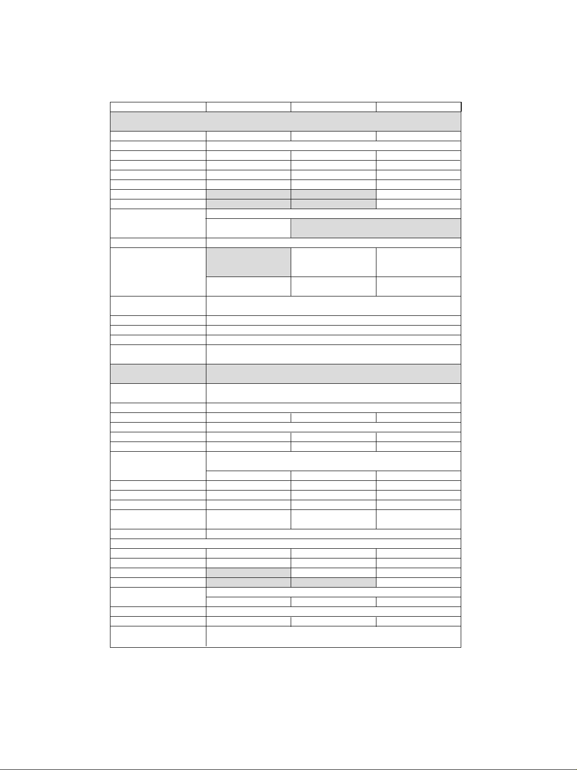
Model PM 5136 PM 5138A PM 5139
Frequency characteristics
Nominal Range 0.1 mHz – 5 MHz 0.1 mHz - 10 MHz 0.1 mHz – 20 MHz
Operational Range
Sine, pos/neg pulse 5 MHz 10 MHz 20 MHz
Square wave 5 MHz 10 MHz 20 MHz
Triangle 500 kHz 500 kHz 500 kHz
Pos./neg. sawtooth 20 MHz 50 kHz 50 kHz
Sine … , triangle pulse 50 kHz
Haversine 50 kHz
4_ digits, max. 0.1 mHz
Resolution 10 Hz (fC>200kHz)
*3
Setting error ± 2 x 10⁻⁶(± 2 ppm)
(fC≥5MHz) (fC>10MHz)
Residual FM deviation <10ppm, 1ppm typical <10ppm, 1ppm typical
(measuring bandwidth
10Hz-20kHz) <100Hz, 13Hz typical (fC≤5MHz) (fC≤10 MH z )
<100Hz, 13Hz typical <100Hz, 13Hz typical
Phase noise at 1kHz < -80dBc/Hz
distance from carrier
Temperature coëfficient <±0.2ppm / K
Aging <±1ppm / year
Drift <±0.3ppm in 7 hours
Synchronization by an f
REF
=10MHz/N, N=1, 2, 3...10
external reference
Output characteristics
Main Output
Connector BNC socket On front
Impedance 50Ω 50Ω or 600Ω 50Ω or LOW Z
O
Load capability Short circuit proof
Max. external voltage ±15V < 3min 50Ω: ±15V 50Ω: ±15V < 3min
600Ω: ±24V LOW ZO: ±12V < 3min
AC voltage independent of DC setting within: ….
Ranges ± 10V window ± 20V window ± 10V window
I resolution 1 mV 0 - 0.200 Vpp 0 - 0.400 Vpp 0 - 0.200 Vpp
II resolution 10mV 0.20 - 2.00 Vpp 0.40 - 4.00 Vpp 0.20 - 2.00 Vpp
III resolution 100 mV 2.0 - 20.0 Vpp 4.0 - 40.0 Vpp 2.0 - 20.0 Vpp
Accuracy for AC voltages > 10mVpp > 20mVpp > 10mVpp
Basic setting error
*2
±2.0%, 1Hz < fC< 200kHz
Amplitude flatness
*2
fC: 1Hz-200kHz ±0.03dB ±0.03dB ±0.03dB
f
C
: 200kHz -5MHz ±0.07dB ±0.07dB ±0.07dB
fC: 5MHz -10MHz ±0.1dB ±0.1dB
f
C
: 10MHz -20MHz ±0.2dB
DC voltage independent of AC setting within: …
± 10V window ± 20V window ± 10V window
Range (open circuit) ±10V resolution 100mV
Error limits
*2
±2.0% ±50mV ±2.0% ±100mV ±2.0% ±50mV
TTL Output 0/5V, Z0=50Ω BNC on rear panel
Fan-out > 4 TTL inputs
 Loading...