


 Loading...
BT521
Battery Analyzer
Users Manual
May 2014 Rev.1, 07/15
© 2014, 2015 Fluke Corporation. All rights reserved. Specifications are subject to change without notice. All product names are trademarks of their respective companies.
LIMITED WARRANTY AND LIMITATION OF LIABILITY
Each Fluke product is warranted to be free from defects in material and workmanship under normal use and service. The warranty period is three years and begins on the date of shipment. Parts, product repairs, and services are warranted for 90 days. This warranty extends only to the original buyer or end-user customer of a Fluke authorized reseller, and does not apply to fuses, disposable batteries, or to any product which, in Fluke's opinion, has been misused, altered, neglected, contaminated, or damaged by accident or abnormal conditions of operation or handling. Fluke warrants that software will operate substantially in accordance with its functional specifications for 90 days and that it has been properly recorded on non-defective media. Fluke does not warrant that software will be error free or operate without interruption.
Fluke authorized resellers shall extend this warranty on new and unused products to end-user customers only but have no authority to extend a greater or different warranty on behalf of Fluke. Warranty support is available only if product is purchased through a Fluke authorized sales outlet or Buyer has paid the applicable international price. Fluke reserves the right to invoice Buyer for importation costs of repair/replacement parts when product purchased in one country is submitted for repair in another country.
Fluke's warranty obligation is limited, at Fluke's option, to refund of the purchase price, free of charge repair, or replacement of a defective product which is returned to a Fluke authorized service center within the warranty period.
To obtain warranty service, contact your nearest Fluke authorized service center to obtain return authorization information, then send the product to that service center, with a description of the difficulty, postage and insurance prepaid (FOB Destination). Fluke assumes no risk for damage in transit. Following warranty repair, the product will be returned to Buyer, transportation prepaid (FOB Destination). If Fluke determines that failure was caused by neglect, misuse, contamination, alteration, accident, or abnormal condition of operation or handling, including overvoltage failures caused by use outside the product’s specified rating, or normal wear and tear of mechanical components, Fluke will provide an estimate of repair costs and obtain authorization before commencing the work. Following repair, the product will be returned to the Buyer transportation prepaid and the Buyer will be billed for the repair and return transportation charges (FOB Shipping Point).
THIS WARRANTY IS BUYER'S SOLE AND EXCLUSIVE REMEDY AND IS IN LIEU OF ALL OTHER WARRANTIES, EXPRESS OR IMPLIED, INCLUDING BUT NOT LIMITED TO ANY IMPLIED WARRANTY OF MERCHANTABILITY OR FITNESS FOR A PARTICULAR PURPOSE. FLUKE SHALL NOT BE LIABLE FOR ANY SPECIAL, INDIRECT, INCIDENTAL OR CONSEQUENTIAL DAMAGES OR LOSSES, INCLUDING LOSS OF DATA, ARISING FROM ANY CAUSE OR THEORY.
Since some countries or states do not allow limitation of the term of an implied warranty, or exclusion or limitation of incidental or consequential damages, the limitations and exclusions of this warranty may not apply to every buyer. If any provision of this Warranty is held invalid or unenforceable by a court or other decision-maker of competent jurisdiction, such holding will not affect the validity or enforceability of any other provision.
Fluke Corporation |
Fluke Europe B.V. |
P.O. Box 9090 |
P.O. Box 1186 |
Everett, WA 98206-9090 |
5602 BD Eindhoven |
U.S.A. |
The Netherlands |
11/99
Table of Contents
Chapter |
Title |
Page |
1 |
Product Overview and Specifications ............................................... |
1-1 |
|
Introduction............................................................................................ |
1-1 |
|
Contact Fluke ........................................................................................ |
1-1 |
|
Product Overview .................................................................................. |
1-1 |
|
Standard Equipment.............................................................................. |
1-3 |
|
Safety Information ................................................................................. |
1-5 |
|
Radio Frequency Data .......................................................................... |
1-8 |
|
Keys and I/O Terminals......................................................................... |
1-8 |
|
LCD Display .......................................................................................... |
1-10 |
|
Specifications ........................................................................................ |
1-11 |
|
General Specifications....................................................................... |
1-11 |
|
Accuracy Specifications..................................................................... |
1-12 |
|
Records Capacity .............................................................................. |
1-13 |
2 |
Setup .................................................................................................... |
2-1 |
|
Introduction............................................................................................ |
2-1 |
|
Tilt Stand ............................................................................................... |
2-1 |
|
Belt Strap............................................................................................... |
2-2 |
|
Adjust Display Contrast ......................................................................... |
2-3 |
|
Set Language ........................................................................................ |
2-3 |
|
Set Date and Time ................................................................................ |
2-3 |
|
Turn On/Off Beep .................................................................................. |
2-4 |
|
AutoHold and AutoSave Modes ............................................................ |
2-4 |
|
Set Auto Power Off Time....................................................................... |
2-5 |
|
View Device Information........................................................................ |
2-6 |
|
Reset to Factory Mode .......................................................................... |
2-6 |
|
View Memory Usage Information .......................................................... |
2-6 |
3 |
Use the Product................................................................................... |
3-1 |
|
Introduction............................................................................................ |
3-1 |
|
Switch Between Meter Mode and Sequence Mode............................... |
3-1 |
|
Use a Profile in Sequence Mode........................................................... |
3-3 |
|
Manage Profiles................................................................................. |
3-3 |
i

BT521
Users Manual
|
Create a Profile.................................................................................. |
3-4 |
|
Edit a Profile ...................................................................................... |
3-5 |
|
Edit a Profile During Creation ........................................................ |
3-5 |
|
Modify a Profile During Measurement ........................................... |
3-5 |
|
Load a Profile .................................................................................... |
3-5 |
|
Load a Profile When Switched to Sequence Mode ....................... |
3-6 |
|
Load a Profile During Measurement in Sequence Mode............... |
3-6 |
|
Make Measurements............................................................................. |
3-7 |
|
Test Battery Internal Resistance and Voltage ................................... |
3-7 |
|
Battery Test Probes....................................................................... |
3-8 |
|
View Test Readings on the Screen ............................................... |
3-9 |
|
Measure Strap resistance in sequence mode ............................... |
3-10 |
|
Save Battery Test Readings.......................................................... |
3-10 |
|
Erase Test Readings ..................................................................... |
3-10 |
|
Activate Low-Pass Filter for Resistance Measurement ................. |
3-10 |
|
Set Measurement Thresholds ....................................................... |
3-11 |
|
How the Thresholds Work ............................................................. |
3-11 |
|
Measure Discharge Voltage .............................................................. |
3-12 |
|
Make Measurements ..................................................................... |
3-12 |
|
Typical Display .............................................................................. |
3-12 |
|
Measure DC Voltage ......................................................................... |
3-14 |
|
Set Measurement Range............................................................... |
3-14 |
|
Save DC Voltage Readings........................................................... |
3-14 |
|
Measure AC Voltage ......................................................................... |
3-15 |
|
Measurement Range ..................................................................... |
3-15 |
|
Save AC Voltage Readings ........................................................... |
3-15 |
|
Measure Ripple Voltage .................................................................... |
3-16 |
|
Set Measurement Range............................................................... |
3-16 |
|
Save Ripple Voltage Readings...................................................... |
3-16 |
|
Measure Current (AUX Function) ...................................................... |
3-17 |
|
Set Measurement Range............................................................... |
3-17 |
|
Save Current Measurement Readings .......................................... |
3-17 |
|
Use the i410 Current Clamp .......................................................... |
3-17 |
|
Measure Voltage with TL175............................................................. |
3-18 |
4 |
Use the BTL21 Interactive Test Probe............................................... |
4-1 |
|
Introduction............................................................................................ |
4-1 |
|
BTL21 Overview.................................................................................... |
4-1 |
|
Connect the Probe to the Product ......................................................... |
4-2 |
|
Configure the Interactive Test Probe on the Product ............................ |
4-2 |
|
Set the Audio..................................................................................... |
4-2 |
|
Set Temperature Unit ........................................................................ |
4-2 |
|
Set Emissivity Value .......................................................................... |
4-3 |
|
Turn On/Off Power ................................................................................ |
4-5 |
|
Understand the Display ......................................................................... |
4-5 |
|
Long and Short Extenders..................................................................... |
4-6 |
|
Replace the Probe Tips......................................................................... |
4-7 |
|
Zero Calibration..................................................................................... |
4-8 |
|
Measure Temperature........................................................................... |
4-9 |
5 |
View Memory ....................................................................................... |
5-1 |
|
Introduction............................................................................................ |
5-1 |
|
View Data Saved in Meter Mode........................................................... |
5-1 |
|
Delete Data Saved in Meter Mode ........................................................ |
5-2 |
ii
|
|
Contents (continued) |
|
View Profiles Saved in Sequence Mode ............................................... |
5-3 |
|
Delete Profiles Saved in Sequence Mode............................................. |
5-3 |
6 |
Connection to PC or Mobile Device................................................... |
6-1 |
|
Introduction............................................................................................ |
6-1 |
|
Connect the Product to PC.................................................................... |
6-1 |
|
Connect the Product to a Mobile Device ............................................... |
6-2 |
7 |
Maintenance......................................................................................... |
7-1 |
|
Introduction............................................................................................ |
7-1 |
|
Install or Replace the Battery Pack ....................................................... |
7-3 |
|
Replace the Fuse .................................................................................. |
7-4 |
|
Clean the Product.................................................................................. |
7-5 |
|
Charge the Battery ................................................................................ |
7-5 |
|
Parts and Accessories........................................................................... |
7-7 |
iii

BT521
Users Manual
iv
List of Tables
Table |
Title |
Page |
1-1. |
Standard Equipment.................................................................................. |
1-3 |
1-2. |
Symbols..................................................................................................... |
1-7 |
1-3. |
Keys .......................................................................................................... |
1-8 |
1-4. Typical Elements on the LCD Display ....................................................... |
1-10 |
|
4-1. Elements of the Interactive Test Probe ..................................................... |
4-2 |
|
4-2. |
Emissivity Table ........................................................................................ |
4-3 |
4-3. Typical Elements on the BTL21 Display.................................................... |
4-5 |
|
7-1. |
Parts and Accessories............................................................................... |
7-7 |
v

BT521
Users Manual
vi
List of Figures
Figure |
Title |
Page |
1-1. |
Standard Equipment.................................................................................. |
1-4 |
1-2. |
I/O Terminals............................................................................................. |
1-9 |
2-1. |
Tilt Stand. .................................................................................................. |
2-1 |
2-2. |
The Belt Strap ........................................................................................... |
2-2 |
3-1. Test Battery Internal Resistance and Voltage ........................................... |
3-7 |
|
3-2. Connect Test Probe to Battery .................................................................. |
3-8 |
|
3-3. |
Measure DC Voltage ................................................................................. |
3-14 |
3-4. |
Measure AC Voltage ................................................................................. |
3-15 |
3-5. |
AUX function ............................................................................................. |
3-17 |
3-6. Measure DC Voltage with TL175 .............................................................. |
3-18 |
|
4-1. BTL21 Interactive Test Probe.................................................................... |
4-1 |
|
4-2. Long and Short Probes ............................................................................. |
4-6 |
|
4-3. Replace the 4-Wire Pins............................................................................ |
4-7 |
|
4-4. |
Zero Calibration Setup .............................................................................. |
4-8 |
4-5. Meaure the Temperature of a Battery Pole ............................................... |
4-9 |
|
6-1. |
Connection to PC ...................................................................................... |
6-1 |
7-1. Install or Replace a Battery Pack .............................................................. |
7-3 |
|
7-2. |
Replace the Fuse ...................................................................................... |
7-4 |
7-3. |
Charge the Battery .................................................................................... |
7-6 |
vii

BT521
Users Manual
viii
Chapter 1
Product Overview and Specifications
Introduction
This chapter supplies information about the Product, safety information, contact information, and specifications.
Contact Fluke
To contact Fluke, call one of the following telephone numbers:
•Technical Support USA: 1-800-44-FLUKE (1-800-443-5853)
•Calibration/Repair USA: 1-888-99-FLUKE (1-888-993-5853)
•Canada: 1-800-36-FLUKE (1-800-363-5853)
•Europe: +31 402-675-200
•China: +86-400-810-3435
•Japan: +81-3-6714-3114
•Singapore: +65-6799-5566
•Anywhere in the world: +1-425-446-5500
Or, visit Fluke's website at www.fluke.com.
To register your product, visit http://register.fluke.com.
To view, print, or download the latest manual supplement, visit http://enus.fluke.com/support/manuals.
Product Overview
The Fluke BT521 Battery Analyzer (the Product) is a multifunctional meter designed for the test and measurement of a stationary battery system. The Product can measure the battery internal resistance and voltages. These measurements can be used to determine the overall condition of the system. It can also measure electrical parameters for battery system maintenance, including dc voltage up to 1000 V, ac voltage up to 600 V, and ripple voltage.
Features of the Product include:
•CAT III 600 V Safety Rated – The Product can measure a maximum of 600 V ac in a Category III environment.
•Battery Internal Resistance – Via the Kelvin connections, the Product measures the internal resistance. An increase in the internal resistance from a known baseline indicates the battery is deteriorating. The testing takes less than 3 seconds.
1-1

BT521
Users Manual
•Battery Voltage – During the internal resistance test, the Product also measures the voltage of the battery under test.
•Negative Post Temperature – With the BTL21 Interactive Test Probe, the Product measures the negative post temperature via an IR sensor near the black test tip. During the test of battery internal resistance, the temperature reading shows on the LCD display of the interactive test probe and is stored in the Product memory.
•Discharge Volts – The Discharge mode collects the voltage of each battery several times at a certain interval during a discharge or load test. Users can calculate the time a battery takes to drop to the cut-off voltage and use this time to determine the capacity loss of this battery.
•Ripple Voltage Test – Measures the unwanted residual ac component of the rectified voltage in dc charging and inverter circuits. Allows users to test ac components in dc charging circuits and find one of the root causes of battery deterioration.
•Current: Via the clamp accessory and adapter, the AC and DC current can be tested and then stored in the memory.
•Meter and Sequence Modes – The Meter mode is used for a quick test or troubleshooting. In this mode you can save and read the readings in a time sequence. The Sequence mode is for maintenance tasks with multiple power systems and battery strings. Before a task starts, users can configure a profile for the task for data management and report generation.
•Threshold and Warning – Users can configure a maximum of 10 sets of thresholds and receive a Pass/Fail/Warning indication after each measurement.
•AutoHold – When AutoHold is turned on, the Product freezes the reading when it remains stable for 1 second. The frozen reading is released when a new measurement starts.
•AutoSave – When the AutoSave mode is on, measured values are saved to the internal memory of the Product automatically after AutoHold.
•Fluke Battery Analyzer Software – Easily import data from the Product to a PC. The measurement data and battery profile information is stored and archived with the Analyzer Software and can be used for comparison and trend analysis. All measurement data, battery profile and analysis information can be used to easily generate reports.
1-2

Product Overview and Specifications |
1 |
Standard Equipment |
Standard Equipment
Items listed in Table 1-1 are included with the Product. Figure 1-1 shows the items.
Table 1-1. Standard Equipment
Item No. |
Description |
Quantity |
|
|
|
|
|
|
Mainframe |
1 |
|
|
|
|
|
|
BTL10, Basic Test Lead |
1 |
|
|
|
|
|
|
TL175, TwistGuard™ Test Leads |
1 |
|
|
|
|
|
|
BTL_A, Voltage/Current Probe Adapter |
1 |
|
|
|
|
|
|
BTL21, Interactive Test Probe set, with extender and |
1 |
|
temperature sensor |
|||
|
|
||
|
|
|
|
|
i410, AC/DC Current Clamp |
1 |
|
|
|
|
|
|
BP500, 7.4 V 3000 mAh Lithium-ion battery |
1 |
|
|
|
|
|
|
BC500, 18 V dc charger |
1 |
|
|
|
|
|
|
Power cord |
1 |
|
|
|
|
|
|
Standard mini-b USB cable (cable length: 1 m) |
1 |
|
|
|
|
|
|
BCR, Zero calibration board |
1 |
|
|
|
|
|
|
Shoulder strap |
1 |
|
|
|
|
|
|
Belt strap |
1 |
|
|
|
|
|
|
Magnetic plate |
1 |
|
|
|
|
|
|
C500L Soft carrying case, large |
1 |
|
|
|
|
|
|
Spare fuse |
2 |
|
|
|
|
|
|
Paper battery tags |
100 |
|
|
|
|
|
-- |
Safety Sheet, not shown |
1 |
|
|
|
|
|
-- |
Warranty card, not shown |
1 |
|
|
|
|
|
-- |
Quick Reference Guide, not shown |
1 |
|
|
|
|
|
-- |
FlukeView® Battery (CD) containing USB driver and manuals |
1 |
|
in all languages, not shown |
|||
|
|
||
|
|
|
1-3

BT521
Users Manual
1 |
2 |
3 |
|
|
|
|
|
|
|
|
|
4
5
6
9
7
8
11
10
12
13
15 |
16 |
14
17
hsz056.eps
Figure 1-1. Standard Equipment
1-4

Product Overview and Specifications |
1 |
Safety Information |
Safety Information
A Warning identifies conditions and procedures that are dangerous to the user. A Caution identifies conditions and procedures that can cause damage to the Product or the equipment under test.
Warning
To prevent possible electrical shock, fire, or personal injury:
•Carefully read all instructions.
•Read all safety information before you use the Product.
•Use the Product only as specified, or the protection supplied by the Product can be compromised.
•Do not use the Product around explosive gas, vapor, or in damp or wet environments.
•Do not use the Product if it is damaged.
•Do not use the Product if it operates incorrectly.
•Do not apply more than the rated voltage, between the terminals or between each terminal and earth ground.
•Do not touch voltages > 30 V ac rms, 42 V ac peak, or 60 V dc.
•Do not exceed the Measurement Category (CAT) rating of the lowest rated individual component of a Product, probe, or accessory.
•Do not use the HOLD function to measure unknown potentials. When HOLD is turned on, the display does not change when a different potential is measured.
•Use the Current Clamp only as specified in the operating instructions. Otherwise the clamp’s safety features may not protect you.
•Do not hold the Current Clamp anywhere beyond the tactile barrier.
•Before each use, inspect the Current Clamp. Look for cracks or missing portions of the clamp housing or output cable insulation. Also look for loose or weakened components. Pay particular attention to the insulation surrounding the jaws.
•Never use the clamp on a circuit with voltages higher than 600 V (CAT III) or a frequency higher than 400 Hz.
•Use extreme caution when working around bare conductors or bus bars. Contact with the conductor could result in electric shock.
•Do not use test leads if they are damaged. Examine the test leads for damaged insulation or exposed metal, or if the wear indicator shows. Check test lead continuity.
•Connect the common test lead before the live test lead and remove the live test lead before the common test lead.
1-5

BT521
Users Manual
•Avoid simultaneous contact with battery and frame racks or hardware that may be grounded.
•Comply with local and national safety codes. Use personal protective equipment (approved rubber gloves, face protection, and flame-resistant clothes) to prevent shock and arc blast injury where hazardous live conductors are exposed.
•Examine the case before you use the Product. Look for cracks or missing plastic. Carefully look at the insulation around the terminals.
•Use only correct measurement category (CAT), voltage, and amperage rated probes, test leads, and adapters for the measurement.
•Measure a known voltage first to make sure that the Product operates correctly.
•Limit operation to the specified measurement category, voltage, or amperage ratings.
•Keep fingers behind the finger guards on the probes.
•Remove all probes, test leads, and accessories before the battery door is opened.
•Use the correct terminals, function, and range for measurements.
•Use only current probes, test leads, and adapters supplied with the Product.
•Install the CAT III protective cap of test lead when you use the product in CAT III environment. The CAT III protective cap decreases the exposed probe metal to < 4 mm.
•Do not operate the Product with covers removed or the case open. Hazardous voltage exposure is possible.
1-6

Product Overview and Specifications |
1 |
Safety Information |
See Table 1-2 for a list of symbols used in this manual and on the Product.
Table 1-2. Symbols
Symbol |
Description |
Symbol |
Description |
|
|
|
|
|
|
|
WARNING. RISK OF DANGER. |
|
AC (Alternating Current) |
|
|
See manual. |
|
|
|
|
WARNING. HAZARDOUS |
|
DC (Direct Current) |
|
|
VOLTAGE. Risk of electric shock. |
|
|
|
|
Earth |
|
Fuse |
|
|
|
|
|
|
|
Measurement Category II is |
|
|
|
|
applicable to test and measuring |
|
Measurement Category III is applicable to |
|
|
circuits connected directly to |
|
test and measuring circuits connected to the |
|
utilization points (socket outlets |
distribution part of the building’s low-voltage |
|||
|
and similar points) of the low- |
|
MAINS installation. |
|
|
voltage MAINS installation. |
|
|
|
|
|
|
|
|
|
Measurement Category IV is |
|
|
|
|
applicable to test and measuring |
|
Conforms to relevant South Korean EMC |
|
|
circuits connected at the source |
|
||
Standards. |
||||
|
of the building’s low-voltage |
|
||
|
|
|
||
|
MAINS installation. |
|
|
|
|
|
|
|
|
|
Certified by TÜV SÜD Product |
|
Certified by CSA Group to North American |
|
Service. |
safety standards. |
|||
|
|
|
|
|
|
Conforms to European Union |
|
Conforms to relevant Australian EMC |
|
|
directives. |
|
Standards. |
|
|
|
|
|
|
|
This product complies with the WEEE Directive marking requirements. The affixed label |
|||
|
indicates that you must not discard this electrical/electronic product in domestic household |
|||
waste. Product Category: With reference to the equipment types in the WEEE Directive Annex |
||||
|
I, this product is classed as category 9 "Monitoring and Control Instrumentation" product. Do |
|||
|
not dispose of this product as unsorted municipal waste. |
|||
|
|
|
|
|
1-7
BT521
Users Manual
Radio Frequency Data
See the Radio Frequency Data for Class A file on the Fluke website.
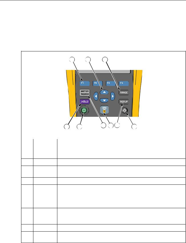
Keys and I/O Terminals
Table 1-3 identifies and describes the keys.
Table 1-3. Keys
1 |
2 |
3 |
|
|
|
|
|
9 |
8 |
7 |
6 |
5 |
4 |
|
|
|
|
|
|
|
hsz001.eps |
|
|
|
|
|
|
|
|
Item |
Key |
|
|
|
|
Function |
|
|
|
|
|
|
|
|
|
|
12 |
Softkeys that work flexibly for various functions on the display. |
|||||
34 |
|||||||
L Selects an item in a menu and scrolls through information.
|
|
Switches between manual ranging and auto ranging. Cycles through all ranges in |
|
manual ranging mode. |
|||
|
|
Turns on or turns off backlight.
|
|
Opens the Setup menu for configurations such as contrast, language, date/time, |
|
and power off time. |
|||
|
|
||
|
|
|
|
|
|
Enables connection between the Product and nearby mobile devices for data |
|
|
transmission. |
||
|
|
Switches between Meter and Sequence measurement modes. For details, see
M Chapter 3. Switches between Meter and Sequence memories. For details, see Chapter 5.
Turns on or turns off the Product.
|
|
Freezes the current reading on the display and allows the display reading to be |
|
saved. |
|||
|
|
1-8
Product Overview and Specifications |
1 |
Keys and I/O Terminals |
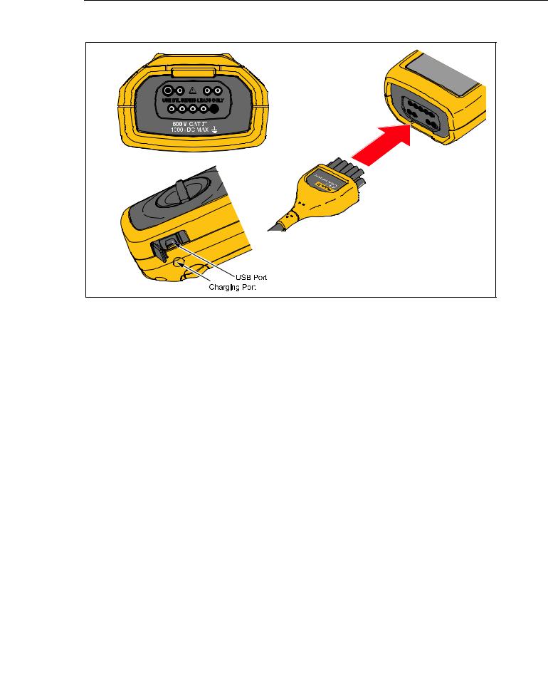
Figure 1-2 shows the terminals of the Product.
hsz002.eps |
Figure 1-2. I/O Terminals |
1-9
BT521
Users Manual
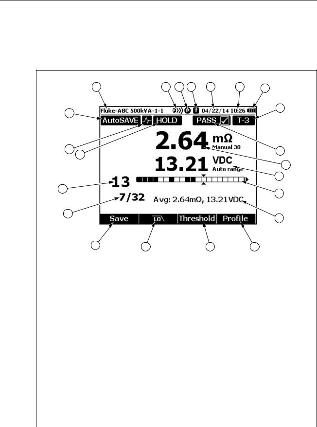
LCD Display
The Product has an LCD display that shows different elements for each measurement function. Table 1-4 describes the typical elements for battery internal resistance measurement in Sequence mode.
Table 1-4. Typical Elements on the LCD Display
1 |
22 |
21
20
19 |
18 |
17 |
2 |
3 |
4 |
5 |
16 |
15 |
6 |
7 |
8 |
9 |
10 |
11 |
12 |
13 |
14 |
hsz055.eps
Item |
Description |
Item |
Description |
|
|
|
|
|
Profile name |
|
Progress bar (Sequence mode only) |
|
Bluetooth connection is on |
|
Average readings |
|
Probe connection status. A full circle means |
|
Softkey F4 – Profile |
|
connected; an empty circle means not |
|
|
|
connected |
|
|
|
Temperature module connection status. A |
|
|
|
full circle means connected; an empty circle |
|
Softkey F3 – Threshold |
|
means not connected |
|
|
|
Current date |
|
Softkey F2 – Low Pass Filter |
|
Current time |
|
Softkey F1 – Save (save current reading) |
|
Battery usage |
|
Tested batteries VS Total number of |
batteries in a string |
|||
|
Threshold indication |
|
Cursor position |
|
Test result (PASS, WARN, or FAIL) |
|
At least one “data hold” succeeded (manual |
|
or auto) |
||
|
Reading of battery internal resistance |
|
AutoHold function enabled |
|
Voltage reading |
|
AutoSave function enabled |
1-10
|
Product Overview and Specifications |
|
|
Specifications |
1 |
Specifications |
|
|
General Specifications |
|
|
Fuse Protection for Resistance...................... |
0.44 A (44/100 A, 440 mA), 1000 V FAST Fuse, Fluke specified part |
|
|
only |
|
Power Supply |
|
|
Battery power...................................................... |
BP500 smart battery pack: double cell lithium-ion, 7.4 V, 3000 mAh |
|
Battery life........................................................... |
>8 hours in continuous full-load operation |
|
Battery charging time.......................................... |
≤4 hours |
|
Power adapter output voltage............................. |
Use only BC500 battery charger: 18 V, 840 mA |
|
Line power .......................................................... |
100 V ac to 240 V ac adapter with country specific plug |
|
Frequency........................................................... |
50 Hz to 60 Hz |
|
Temperature |
|
|
Operating ............................................................ |
0 °C to 40 °C |
|
Storage ............................................................... |
-20 °C to 50 °C |
|
Lithium-ion battery charging ............................... |
0 °C to 40 °C |
|
Relative Humidity (non-condensing, 10 °C) |
|
|
Operating............................................................ |
≤80 % at 10 °C to 30 °C |
|
|
≤75 % at 30 °C to 40 °C |
|
Altitude |
|
|
Operating............................................................ |
2,000 m |
|
Storage ............................................................... |
12,000 m |
|
Temperature Coefficient....................................... |
0.1 x (specified accuracy) /°C (<18 °C or >28 °C) |
|
Size......................................................................... |
58 x 103 x 220 (mm) |
|
Weight .................................................................... |
850 g |
|
Memory |
|
|
Data/Setup flash memory ................................... |
4 MB |
|
Real-Time Clock.................................................... |
Time and date stamp for measurement. The RTC works >50 days |
|
|
without battery. |
|
IP Rating ................................................................ |
IEC 60529: IP 40 |
|
Safety ..................................................................... |
IEC 61010-1, IEC 61010-2-030, IEC 61010-031, Pollution Degree 2 |
|
|
600 V CAT III, 1000 V dc max; Derated to CAT II with CAT II probe cap |
|
|
installed |
|
EMI, RFI, EMC, RF ................................................. |
IEC 61326-1, IEC 61326-2-2, EN 300 328, EN 301 489-1, EN 301 489- |
|
|
17, FCC Part 15 Subpart C Sections 15.207, 15.209, 15.249 |
|
|
CONTAINS FCC IDs: T68-FWCS, XDULE40-S2 |
|
|
IC: 6627A-FWCS, 8456A-LE4S2 |
|
Electromagnetic Compatibility ............................ |
Applies to use in Korea only. Class A Equipment (Industrial |
|
|
Broadcasting & Communication Equipment)[1] |
|
[1]This product meets requirements for industrial (Class A) electromagnetic wave equipment and seller or user should take notice of it. This equipment is intended for use in business environments and is not to be used in homes.
1-11

BT521
Users Manual
Accuracy Specifications
Accuracy is specified for a period of one year after calibration, at 18 °C to 28 °C (64 °F to 82 °F), with relative humidity to 80 %. Accuracy specifications are given as: ±([% of reading] + [number of least significant digits]). Accuracy specification assumes ambient temperature stable ±1 °C.
Function |
Range |
Resolution |
Accuracy |
|
|
|
|
|
|
|
3 mΩ |
0.001 mΩ |
1 % + 8 |
|
|
|
|
|
|
Battery Internal Resistance[1] |
30 mΩ |
0.01 mΩ |
0.8 % + 6 |
|
|
|
|
||
300 mΩ |
0.1 mΩ |
0.8 % + 6 |
||
|
||||
|
|
|
|
|
|
3000 mΩ |
1 mΩ |
0.8 % + 6 |
|
|
|
|
|
|
|
6 V |
0.001 V |
|
|
|
|
|
|
|
V dc |
60 V |
0.01 V |
0.09 % + 5 |
|
|
|
|||
600 V |
0.1 V |
|||
|
|
|||
|
|
|
|
|
|
1000 V |
1 V |
|
|
|
|
|
|
|
V ac (45 Hz to 500 Hz with low- |
600 V |
0.1 V |
2 % + 10 |
|
pass filter) |
|
|
|
|
Frequency (Display with V ac, |
|
|
|
|
A ac using i410)[2] |
45 Hz to 500 Hz |
0.1 Hz |
0.5 % + 8 |
|
Trigger level: ≥ 10 mV @V ac; |
||||
|
|
|
||
≥ 10 A @A ac |
|
|
|
|
|
|
|
|
|
AC Voltage Ripple (20 kHz |
600 mV |
0.1 mV |
3 % + 20 |
|
max) |
6000 mV |
1 mV |
3 % + 10 |
|
|
||||
|
|
|
|
|
Amps dc/Amps ac (With |
400 A |
1 A |
3.5 % + 2 |
|
accessory Fluke i410) |
||||
|
|
|
||
|
|
|
|
|
Temperature |
0 °C to 60 °C |
1 °C |
2 °C (typical) |
|
|
|
|
|
[1] The measurement is based on ac injection method. The injected source signal is <100 mA, 1 kHz. [2] For A ac frequency measurement, the range is 45 Hz to 400 Hz.
1-12
Loading...