


123

Fluke 123
Industrial ScopeMeter
Users Manual
®
4822 872 00743
January 1997, Rev. 4, 7/99
© 1997, 1999 Fluke Corporation. All rights reserved. Printed in the Netherlands.
All product names are trademarks of their respective companies.

LIMITED WARRANTY & LIMITATION OF LIA BILITY
Each Fluke product is warranted to be free from defects in material and workmanship under normal use and service. The warranty period is three years and begins on the date of shipment. Parts, product repairs and services are warranted for 90 days. This warranty extends only to the original buyer or end-user customer
of a Fluke authorized reseller, and does not apply to fuses, disposable batteries or to any product which, in Fluke’s opinion, has been misused, altered, neglected
or damaged by accident or abnormal conditions of operation or handling. Fluke warrants that software will operate substantially in accordance with its functional
specifications for 90 days and that it has been properly recorded on non-defective media. Fluke does not warrant that software will be error free or operate without
interruption.
Fluke authorized resellers shall extend this warranty on new and unused products to end-user customers only but have no authority to extend a greater or different
warranty on behalf of Fluke. Warranty support is available if product is purchased through a Fluke authorized sales outlet or Buyer has paid the applicable international
price. Fluke reserves the right to invoice Buyer for importation costs of repair/replacement parts when product purchased in one country is submitted for repair in another
country.
Fluke’s warranty obligation is limited, at Fluke’s option, to refund of the purchase price, free of charge repair, or replacement of a defective product which is returned to a
Fluke authorized service center within the warranty period.
To obtain warranty service, contact your nearest Fluke authorized service center or send the product, with a description of the difficulty , postage and insurance prepaid
(FOB Destination), to the nearest Fluke authorized service center. Fluke assumes no risk for damage in transit. Following warranty repair, the product will be returned to
Buyer, transportation prepaid (FOB Destination). If Fluke determines that the failure was caused by misuse, alteration, accident or abnormal condition of operation or
handling, Fluke will provide an estimate of repair costs and obtain authorization before commencing the work. Following repair, the product will be returned to the Buyer
transportation prepaid and the Buyer will be billed for the repair and return transportation charges (FOB Shipping Point).
THIS WARRANTY IS BUYER’S SOLE AND EX CL USI VE REM EDY AND I S I N LI EU O F AL L OTHER WARRANTIES, EX PRESS OR I MPLIED, INCLUDING BUT
NOT LIMITED TO ANY I M PL I ED WARRANTY OF M ERCHANTABI L I TY OR FITNESS FOR A PARTICULAR PURPOSE. FLUKE SHALL NOT BE L I ABL E FO R ANY
SPECIAL, INDIRECT, INCIDENTAL OR CONSEQUENTIAL DAM AGES O R LOSSES, I NCLUDING LOSS OF DATA, WHETHER ARISING FROM BREACH OF
WARRANTY OR BASED ON CONTRACT, TORT, RELIANCE OR ANY OTHER THEORY.
Since some countries or states do not allow limitation of the term of an implied warranty, or exclusion or limitation of incidental or consequential damages, the limitations
and exclusions of this warranty may not apply to every buyer. If any provision of this Warranty is held invalid or unenforceable by a court of competent jurisdiction, such
holding will not affect the validity or enforceability of any other provision.
Fluke Corporation, P.O. Box 9090, Everett, WA 98206-9090 USA, or
Fluke Industrial B.V., P.O. Box 680, 7600 AR, Almelo, The Netherlands

SERVICE CENTERS
To locate an authorized service center, visit us on the World Wide Web:
http://www.fluke.com
or call Fluke using any of the phone numbers listed below:
+1-888-993-5853 in U.S.A. and Canada
+31-402-678-200 in Europe
+1-425-356-5500 from other countries

Table of Contents
Chapter Title Page
Declaration of Conformity.............................................................................................. 1
Unpacking the Test Tool Kit .......................................................................................... 2
Safely Using the Test Tool ............................................................................................ 4
1 Using The Test Tool .................................................................................................... 7
Goal of this Chapter....................................................................................................... 7
Powering the Test Tool.................................................................................................. 7
Resetting the Test Tool ................................................................................................. 8
Changing Backlight........................................................................................................ 9
Reading the Screen....................................................................................................... 10
Making Selections in a Menu......................................................................................... 11
Looking at the Measurement Connections .................................................................... 12
Input A ...................................................................................................................... 12
Input B ...................................................................................................................... 12
COM ........................................................................................................................ 12
i

Fluke 123
Users Manual
Displaying an Unknown Signal with Connect-and-View™ ............................................. 13
Making Measurements................................................................................................... 14
Freezing the Screen....................................................................................................... 16
Holding a Stable Reading .............................................................................................. 16
Making Relative Measurements..................................................................................... 17
Selecting Auto/Manual Ranges...................................................................................... 18
Changing the Graphic Representation on the Screen.................................................... 18
Changing the Amplitude ............................................................................................ 18
Changing the Time Base........................................................................................... 18
Positioning the Waveform on the Screen .................................................................. 19
Smoothing the Waveform.......................................................................................... 20
Displaying the Envelope of a Waveform.................................................................... 21
TrendPlotting a Waveform.............................................................................................. 22
Starting a TrendPlot™ function ................................................................................. 22
Changing the TrendPlot Reading .............................................................................. 23
Turning Off the TrendPlot Display ............................................................................. 23
Acquiring the Waveform................................................................................................. 23
Making a Single Acquisition....................................................................................... 23
Recording Slow Signals over a Long Period of Time ................................................ 25
Selecting AC-Coupling .............................................................................................. 26
Reversing the Polarity of the Displayed Waveform ................................................... 26
Triggering on a Waveform.............................................................................................. 27
Setting Trigger Level and Slope ................................................................................ 27
Selecting the Trigger Parameters.............................................................................. 28
Isolated Triggering..................................................................................................... 29
Triggering on Video Signals ...................................................................................... 29
ii

Contents
(continued)
Triggering on a Specific Video Line .......................................................................... 31
Saving and Recalling a Setup or a Screen.................................................................... 32
Saving Screens......................................................................................................... 32
Recalling Screens..................................................................................................... 33
Deleting Screens ...................................................................................................... 33
Using a Printer............................................................................................................... 34
Using FlukeView
®
Software ........................................................................................... 36
2 Maintaining the Test Tool ........................................................................................... 37
About this Chapter......................................................................................................... 37
Cleaning the Test Tool .................................................................................................. 37
Storing the Test Tool..................................................................................................... 37
Charging the Ni-Cd Battery Pack .................................................................................. 38
Keeping Batteries in Optimal Condition......................................................................... 39
Replacing and Disposing of the Ni-Cd Battery Pack ..................................................... 40
Using and Adjusting 10:1 Scope Probes ....................................................................... 41
Calibrating the Test Tool ............................................................................................... 43
Parts and Accessories................................................................................................... 43
Service Manual......................................................................................................... 43
Standard Accessories............................................................................................... 43
Optional Accessories................................................................................................ 46
3 Tips and Troubleshooting .......................................................................................... 47
Goal of this Chapter....................................................................................................... 47
Using the Tilt Stand....................................................................................................... 47
Resetting the Test Tool ................................................................................................. 48
Changing the Information Language ............................................................................. 48
Changing the Display .................................................................................................... 49
Adjusting the Screen Contrast.................................................................................. 49
iii

Fluke 123
Users Manual
Setting the Grid Display............................................................................................. 49
Changing Date and Time ............................................................................................... 50
Saving Battery Life......................................................................................................... 51
Setting the Power Down Timer.................................................................................. 51
Changing the Auto Set Options...................................................................................... 52
Using Proper Grounding................................................................................................. 53
Solving Printing and Other Communication Errors......................................................... 54
4 Specifications............................................................................................................... 55
Introduction ....................................................................................................................55
Dual Input Oscilloscope.................................................................................................. 56
Vertical....................................................................................................................... 56
Horizontal .................................................................................................................. 57
Trigger....................................................................................................................... 57
Advanced Scope Functions....................................................................................... 58
Dual Input Meter............................................................................................................. 59
Input A and Input B.................................................................................................... 59
Input A....................................................................................................................... 60
Advanced Meter Functions........................................................................................ 61
Miscellaneous................................................................................................................. 62
Environmental ................................................................................................................ 63
Safety............................................................................................................................. 64
iv

Declaration of Conformity
Declaration of Conformity
for
Fluke 123
®
ScopeMeter
Manufacturer
Fluke Industrial B.V.
7602 EA Almelo
The Netherlands
Statement of Conformity
Based on test results using appropriate standards,
the product is in conformity with
Electromagnetic Compatibility Directive 89/336/EEC
Low Voltage Directive 73/23/EEC
test tool
Lelyweg 1
Sample tests
Standards used:
EN 61010.1 (1993)
Safety Requirements for Electrical Equipment for
Measurement, Control, and Laboratory Use
EN 50081-1 (1992)
Electromagnetic Compatibility.
Generic Emission Standard:
EN55022 and EN60555-2
EN 50082-2 (1992)
Electromagnetic Compatibility.
Generic Immunity Standard:
IEC1000-4 -2, -3, -4, -5
The tests have been performed in a
typical configuration.
This Conformity is indicated by the symbol
i.e. “Conformité européenne”.
,
1

Fluke 123
Users Manual
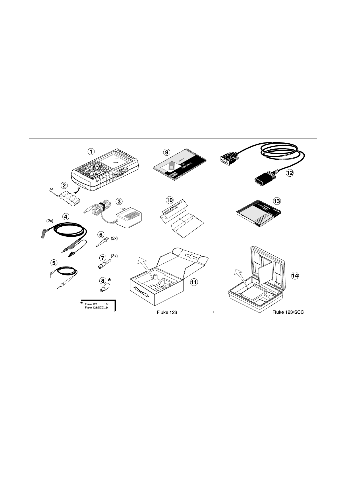
Unpacking the Test Tool Kit
The following items are included in your test tool kit. (see
Figure 1.):
# Description Model
1 Industrial ScopeMeter Test Tool ll
2 Ni-Cd Battery Pack (installed) ll
3 Power Adapter/Battery Charger ll
4 Shielded Test Leads (red and gray) with black ground leads ll
5 Test Lead (black) ll
6 Hook Clips (red and gray) ll
7 Alligator Clips (red, gray, and black) ll
8 Banana-to-BNC Adapter(s) (Black) l (1x) l (2x)
9 Fluke 123 Users Manual (this book) ll
10 Product Registration Card with Envelope ll
11 Shipment box l
12 Optically Isolated RS-232 Adapter/Cable l
13 FlukeView® ScopeMeter® Software for Windows
14 Hard Carrying Case l
®
When new, the rechargeable Ni-Cd battery pack
is not fully charged. See Chapter 2.
Note
123 123/SCC
l
2
Unpacking the Test Tool Kit
Figure 1. ScopeMeter Test Tool Kit
3
Fluke 123
Users Manual
Safely Using the Test Tool
Attention
Carefully read the following safety
information before using the test tool.
Safety Precautions
Specific warning and caution statements, where they
apply, will be found throughout the manual.
A Caution identifies conditions and actions that may
damage the test tool.
A Warning identifies conditions and actions that pose
hazard(s) to the user.
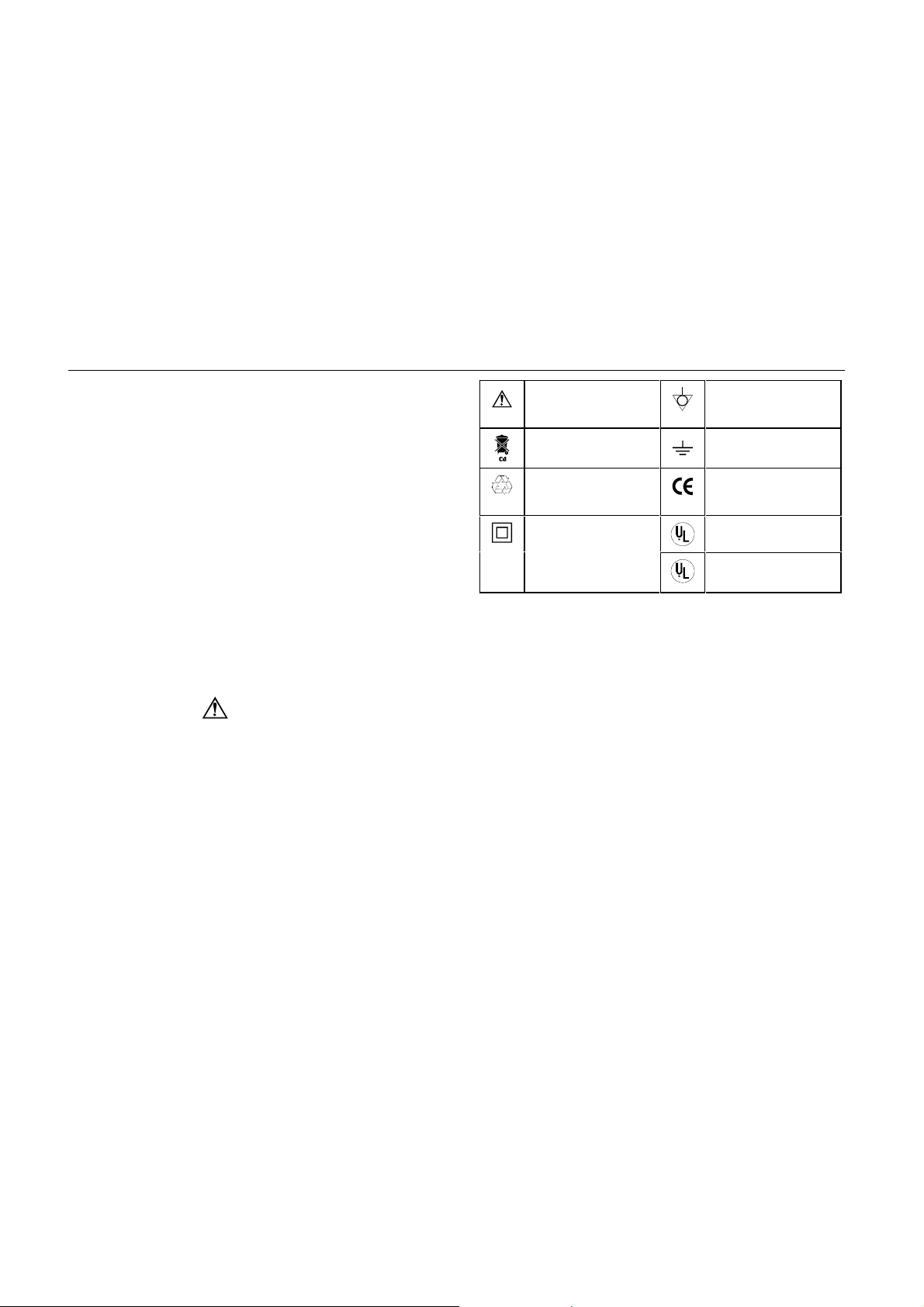
Symbols used on the test tool and in this manual are
explained in the next table.
Warning
To avoid electrical shock, use only Fluke
power supply, Model PM8907 (Power
Adapter/Battery Charger).
See explanation in
manual
Disposal information Earth
Recycling
information
Double Insulation UL 3111 listed
(Protection Class)
Equal potential
inputs
Conformité
Européenne
UL 1244 listed
UL1244
Warning
Should this test tool be used with AC
coupling selected, or manual operation of
amplitude or time base ranges, the measuring
results displayed on the screen may not be
representative of the total signal. This can
result in the presence of dangerous voltages
of more than 42V peak (30V rms), not being
detected. To guarantee user safety, all
signals should first be measured with DC
coupling selected and in fully automatic
mode. This ensures that the full signal
content is measured.
4

Warning
Do the following to avoid electrical shock or
fire if a test tool
connected to more than 42V peak (30V rms):
• Use only test leads and test lead
adapters supplied with the test tool. (or
equivalents as specified in the accessory
list, see Chapter 2.)
• Do not use conventional exposed metal
banana plug connectors.
• Use only one common connection to the
test tool.
• Remove all test leads that are not in use.
• Use 600V (or more) rated and marked test
lead adapters. The maximum allowable
input voltage is 600V.
• Connect the power adapter to the AC
outlet before connecting it to the test
tool.
• Do not insert metal objects in the power
adapter connector.
common input is
Safely Using the Test Tool
The terms ‘Isolated’ or ‘Electrically floating’ are used in
this manual to indicate a measurement in which the test
tool COM (common, also called ground) is connected to a
voltage different from earth ground.
The term “Grounded” is used in this manual to indicate a
measurement in which the test tool COM (common) is
connected to an earth ground potential. For more
information about proper grounding, see Chapter 3.
The test tool COM (common) inputs (red INPUT A shield,
gray INPUT B shield, and black 4-mm banana jack) are
connected internally via self-recovering fault protection.
The input connectors have no exposed metal and are fully
insulated to protect against electrical shock. The black
4 mm banana jack COM (common) can be connected to a
voltage above earth ground for isolated (electrically
floating) measurements and is rated up to 600V rms
above earth ground.
5

Fluke 123
Users Manual
If Safety-Precautions are Impaired
Use of the test tool in a manner not specified may
impair the protection provided by the equipment.
Before use, inspect the test leads for mechanical damage
and replace damaged test leads!
Whenever it is likely that safety has been impaired, the
test tool must be turned off and disconnected from the line
power. The matter should then be referred to qualified
personnel. Safety is likely to be impaired if, for example,
the test tool fails to perform the intended measurements
or shows visible damage.
6
Goal of this Chapter
This Chapter provides a step-by-step introduction to the
test tool. The introduction does not cover all of the
capabilities of the test tool but gives basic examples to
show how to use the menus perform basic operations.
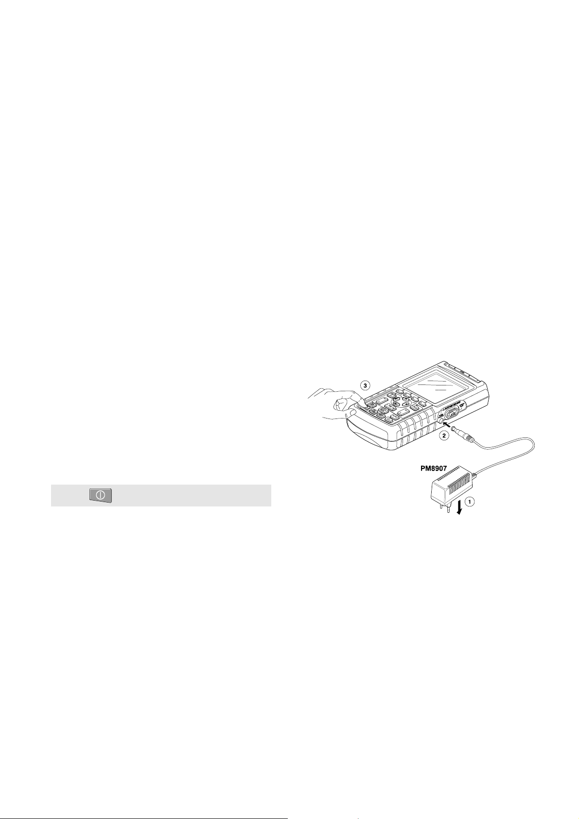
Powering the Test Tool
Follow the procedure (step 1 to 3) in Figure 1-1 to power
the test tool from a standard ac outlet. See Chapter 2 for
battery power instructions.
Turn the test tool on.
Chapter 1
Using The Test Tool
The test tool powers up in its last setup configuration.
Figure 1-1. Powering the Test Tool
7
Fluke 123
Users Manual
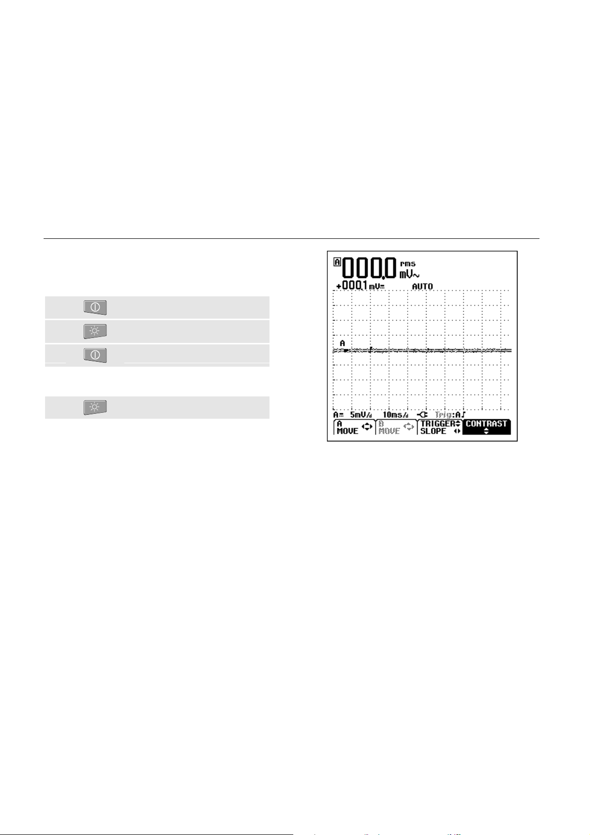
Resetting the Test Tool
If you want to restore the test tool settings as deliv ered from
the factory, do the following:
Turn the test tool off.
ô Press and hold.
í Press and release.
The test tool turns on, and you should hear a double
beep, indicating the Reset was successful.
÷ Release.
Now look at the display; you will see a screen that looks
like Figure 1-2.
Figure 1-2. The Screen After Reset
8

Changing Backlight
After power-up, the screen has a high bright display.
To save battery power, the screen has an economic
brightness display when operated on the battery pack (no
power adapter connected).
To change the brightness of the display , do the following:
Dim the backlight.
ô Brighten the backlight again.
The high brightness increases when you connect the
power adapter.
Note
Using dimmed display lengthens maximum
battery power operation time by about one hour.
Using The Test Tool
Changing Backlight
1
9
Fluke 123
Users Manual
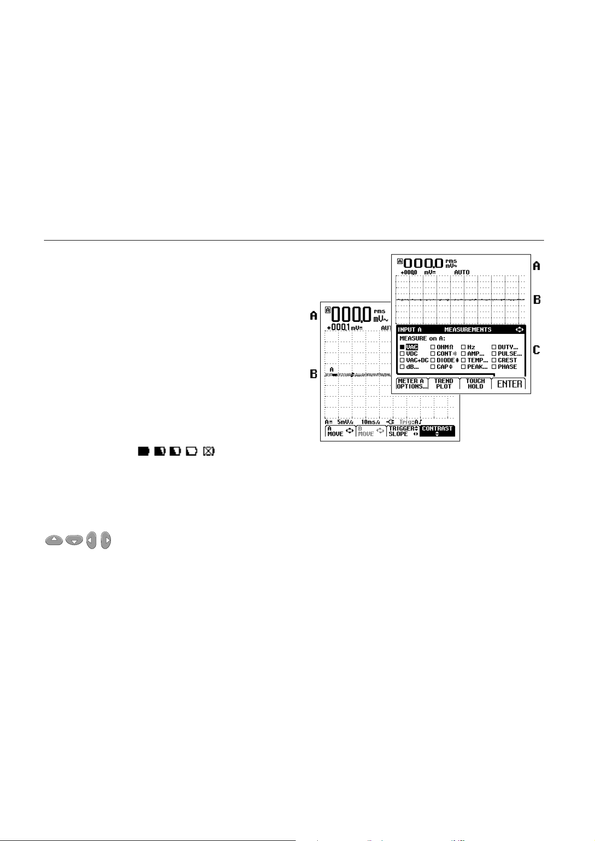
Reading the Screen
The screen is divided into three areas: Reading area,
Waveform area, and Menu area. Refer to Figure 1-3
during the following.
Reading area
Because only input A is on, you will see the input A
readings only.
Waveform area
bottom line displays the ranges/div and the power
indicator (line or battery). Because only input A is on, you
will see the input A waveform only.
When battery powered, the battery indicator
informs you about the condition of the battery
from full to empty:
Menu area (C): Displays the menu that provides choices
available through the blue function keys.
When you change a setup, a part of the screen is used to
display the choices. The area displays one or more menus
with choices accessed with the arrow keys:
(A): Displays the numeric readings.
(B): Displays the input A waveform. The
Note
.
.
10
Figure 1-3. The Screen Area’s
Using The Test Tool
Making Selections in a Menu
1
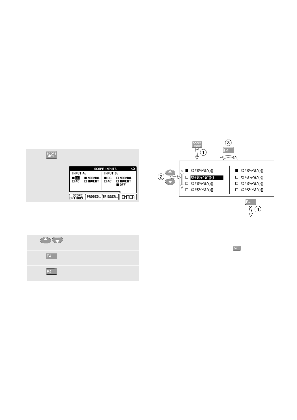
Making Selections in a Menu
Subsequently follow steps to ÷ to open a menu and to
choose an item.
Press the SCOPE MENU key to
open the Scope menu.
Note
Pressing the SCOPE MENU key a second time
closes this menu and resumes normal
measurement. This toggling enables you to
check the menu without destroying your settings.
ô Use the blue arrow keys to
highlight the item.
í Press the blue ‘ENTER’ function
key to confirm selection
÷ Press ‘ENTER’ until you return to
normal mode.
Figure 1-4 shows the basic navigation of the test tool.
Figure 1-4. Basic Navigation
Note
When you do not change an item with the blue
arrow keys, repeatedly pressing
you to step through a menu without changing the
setup of the test tool.
enables
11

Fluke 123
Users Manual
Looking at the Measurement
Connections
Look at the top of the test tool. The test tool provides two
4-mm safety shielded banana jack inputs (red input A and
gray input B) and a safety 4-mm banana jack input (COM).
(See Figure 1-5.)
Input A
You can always use the red input A for all single input
measurements possible with the test tool.
Input B
For measurements on two different signals you can use
the gray input B together with the red input A .
COM
You can use the black COMmon as single ground for low
frequency measurements, and for Continuity, Ohm (Ω),
Diode, and Capacitance measurements.
Warning
To avoid electrical shock or fire, use only one
COM
all connections to COM
potential.
12
(common) connection, or ensure that
are at the same
Figure 1-5. Measurement Connections
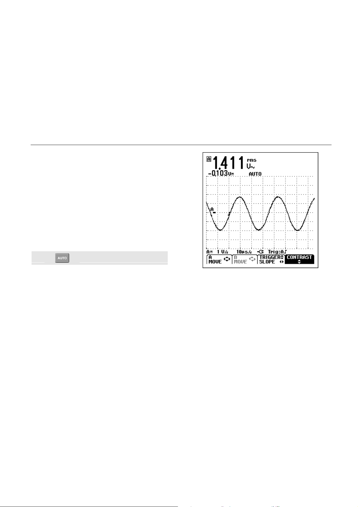
Displaying an Unknown Signal with
Connect-and View™
The Connect-and-View™ function enables hands-off
operation to display complex unknown signals. This
function optimizes the position, range, time base, and
triggering and assures a stable display on nearly all
waveforms. If the signal changes, the setup will track
these changes.
To enable the Connect-and-View™ function, do the
following:
• Connect the red test lead from red input A to the
unknown signal to be measured .
Perform an Auto Set.
Using The Test Tool
Displaying an Unknown Signal with Connect-and View™
1
In the next example, the screen displays “1.411” in large
numbers and “-0.103” in smaller numbers. A scope trace
gives a graphical representation of the waveform.
The trace identifier (A) is visible on left of the waveform
area. The zero icon (
waveform.
-) identifies the ground level of the
Figure 1-6. The Screen After an Auto Set
13
Fluke 123
Users Manual
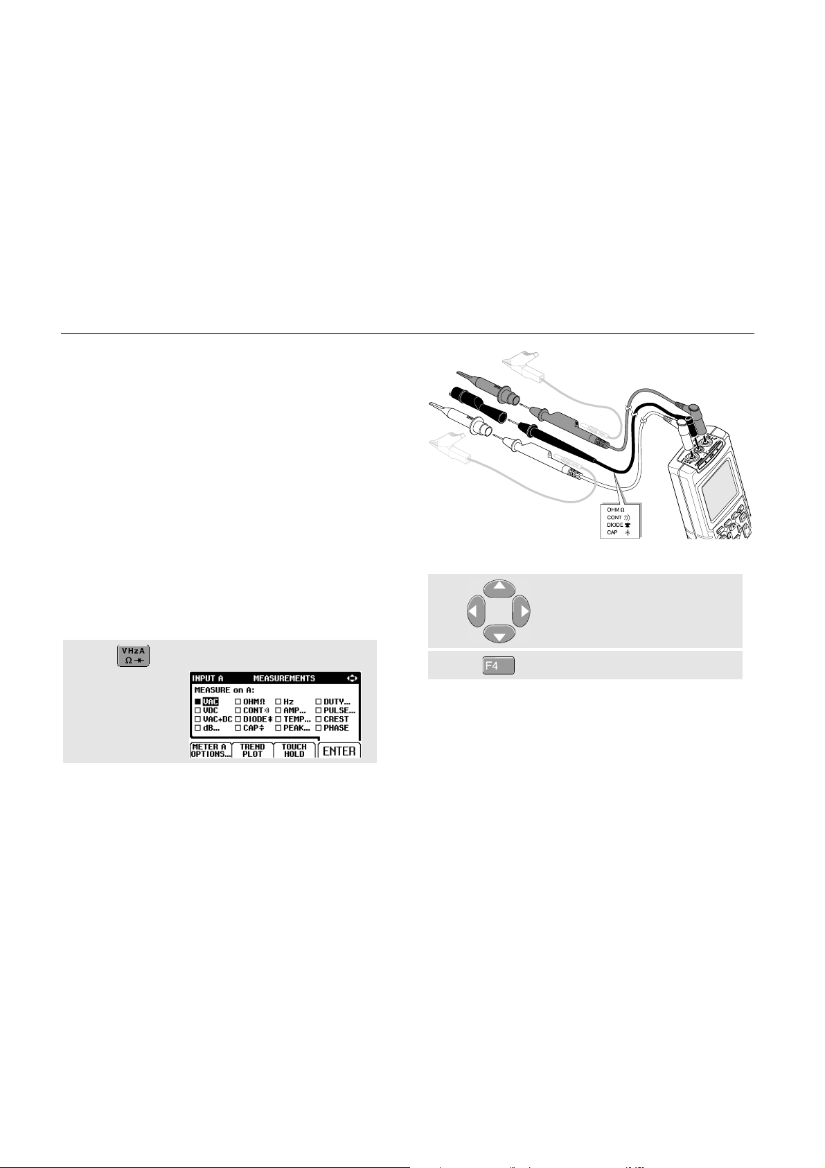
Making Measurements
The reading area displays the numeric readings of the
chosen measurements on the waveform that is applied to
the input jack.
• First connect the red shielded test lead from input A,
and the gray shielded test lead from input B to the
signals to be measured. Connect the short ground
leads to the same ground potential. (See Figure 1-7.)
Note
Ω
For Ohm (
measurements, use the red shielded test lead
from input A and the black unshielded ground
lead from COM (common). (See Figure 1-7.)
To choose a frequency measurement for Input A, do the
following:
), continuity, diode, and capacitance
Figure 1-7. Measurement Setup
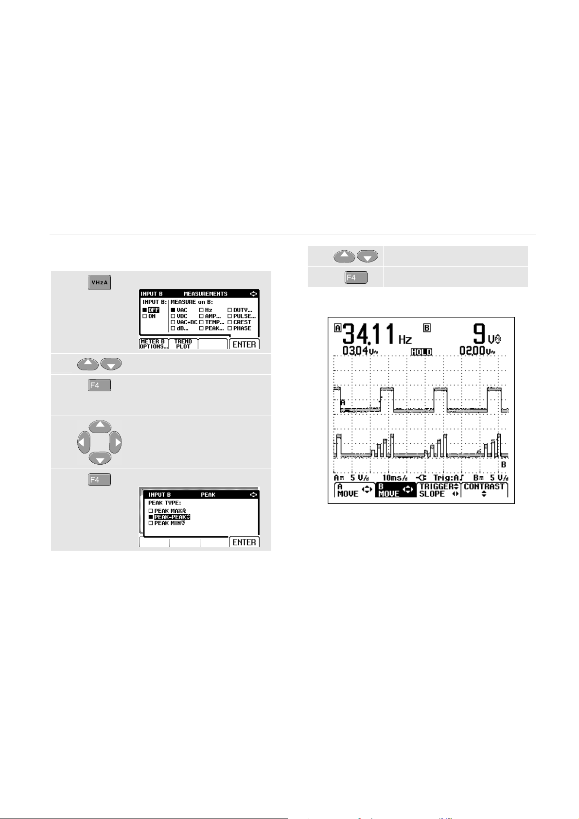
ô Highlight Hz.
Open the INPUT A menu.
14
í Select Hz.
Observe that Hz is now the main reading. The former
main reading has now moved to the smaller secondary
reading position. (See Figure 1-8.)
Using The Test Tool
Making Measurements
1
To choose also a Peak-to-Peak measurement for Input B,
do the following:
ô
í
÷
û
Open the INPUT B menu.
Highlight ON.
Turn Input B on. Observe that the
highlight jumps to the present
main measurement.
Highlight PEAK...
Open the PEAK submenu.
ø
ù
Now, you will see a screen like Figure 1-8.
Figure 1-8. Hz and Vpp as Main Readings
Highlight PEAK-PEAK.
Accept the pk-pk measurement.
15
Fluke 123
Users Manual
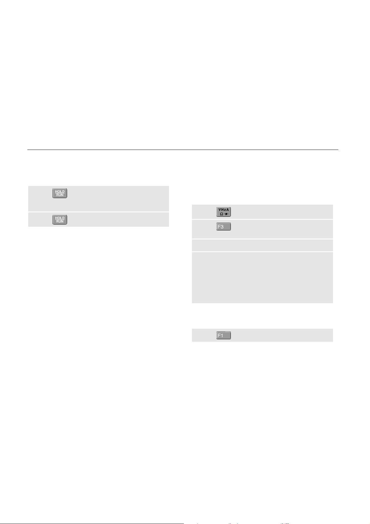
Freezing the Screen
You can freeze the screen (all readings and waveforms)
at any time.
Freeze the screen. HOLD
appears at the bottom of the
reading area.
ô Resume your measurement.
Holding a Stable Reading
The Touch Hold® function captures and freezes the next
stable measurement result. A beep indicates that a stable
measurement has been made.
Use the following procedure for the Touch Hold function:
Open the INPUT A menu.
ô TOUCH HOLD OFF appears on
bottom of the screen.
í Measure the signal.
÷
BEEP)))
Because no special keys accompany the Touch Hold
function, you can use this function for hands-free
measurements.
Wait until an audible beep: now
you have a stable display.
The screen continues to update
with valid readings (and beeps)
as longs as you maintain the
measurement connections.
û Return to normal measurement.
16
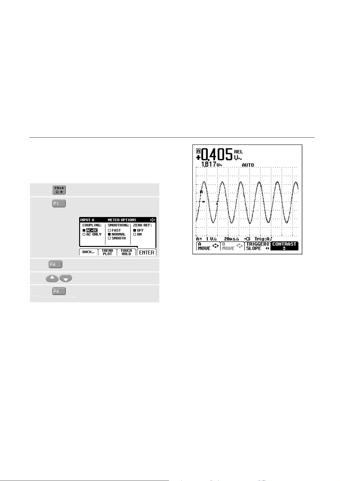
Making Relative Measurements
Zero Reference displays the present measurement result
with respect to the defined value. This feature is useful
when you need to monitor the measured value in relation
to a known good value.
Open the INPUT A menu.
ô Open the METER A OPTIONS
submenu.
Using The Test Tool
Making Relative Measurements
1
í
(2x)
Jump to ZERO REF.
÷ Highlight ON.
û Activate the relative
measurement.
Figure 1-9. Making a Relative Measurement
The relative measurement now becomes the main
reading, while the former main measurement has moved
to the smaller secondary reading position. (See Figure
1-9.)
17
 Loading...