

Page 1

GESTRA
GESTRA Steam Systems
NRG 16-41
NRG 17-41
NRG 19-41
Installation Instructions 810743-01
Level Electrode NRG 16-41
Level Electrode NRG 17-41
Level Electrode NRG 19-41
1
Page 2

Contents
Page
Important Notes
Usage for the intended purpose ..............................................................................................................4
Safety note .............................................................................................................................................4
Danger ...................................................................................................................................................4
Attention .................................................................................................................................................4
ATEX (Atmosphère Explosible) .................................................................................................................4
Explanatory Notes
Scope of supply ...................................................................................................................................... 5
Description .............................................................................................................................................5
Function .................................................................................................................................................6
System components ...............................................................................................................................6
Design .................................................................................................................................................... 6
Technical Data
NRG 16-41, NRG 17-41, NRG 19-41 .......................................................................................................
Corrosion resistance ............................................................................................................................... 8
Sizing .....................................................................................................................................................8
Name plate / marking .............................................................................................................................8
Dimensions NRG 16-41, NRG 17-41 .......................................................................................................
Dimensions NRG 19-41 ........................................................................................................................10
Design
NRG 16-41, NRG 17-41, NRG 19-41 ..................................................................................................... 11
Key .......................................................................................................................................................13
Functional Elements
NRG 16-41, NRG 17-41, NRG 19-41 ..................................................................................................... 12
Key .......................................................................................................................................................13
Installation
NRG 16-41, NRG 17-41, NRG 19-41, step 1 ..........................................................................................14
NRG 16-41, NRG 17-41, NRG 19-41, step 2 ..........................................................................................14
Attention ...............................................................................................................................................14
Note .....................................................................................................................................................14
Tools ..................................................................................................................................................... 14
Examples of installation NRG 16-41, NRG 17-41, NRG 19-41 ................................................................15
Key .......................................................................................................................................................16
7
9
2
Page 3

Contents continued
Page
Wiring
NRG 16-41, NRG 17-41, NRG 19-41 ..................................................................................................... 17
Aligning terminal box ............................................................................................................................ 17
Note .....................................................................................................................................................17
Wiring diagram ..................................................................................................................................... 18
Attention ...............................................................................................................................................19
Tools ..................................................................................................................................................... 19
Basic Settings
CAN bus ...............................................................................................................................................20
Node ID ................................................................................................................................................20
Attention ...............................................................................................................................................20
Factory set default values .....................................................................................................................20
Factory set default node IDs ..................................................................................................................21
Assigning / changing node ID ................................................................................................................21
Attention ...............................................................................................................................................21
Setting code switch ..............................................................................................................................22
Commissioning Procedure
Check wiring ........................................................................................................................................23
Apply mains voltage..............................................................................................................................23
Operation
High-water level limiter (Max alarm) .....................................................................................................23
Note .....................................................................................................................................................23
Malfunctions
Fault finding list for troubleshooting ...................................................................................................... 24
Annex
Declaration of conformity ......................................................................................................................25
3
Page 4
Important Notes
Usage for the intended purpose
Use level electrode type NRG 16-41, NRG 17-41 or NRG 19-41 only in conjunction with control
equipment NRS 1-41 as high-water level limiter (high-level alarm).
Safety note
The equipment must only be installed and commissioned by qualified staff.
Maintenance and service work must only be performed by adequately trained persons who have
a recognized level of competence.
Danger
When loosening the electrode steam or hot water might escape.
This presents the danger of severe scalding. It is therefore essential not to remove
the electrode unless the boiler pressure is verified to be zero.
The electrode is hot during operation. This presents the danger of severe burns to hands
and arms. Installation and maintenance work should only be carried out when the
system is cold.
If the internal ceramic insulation breaks, hot steam can escape through the lateral vent
hole on the electrode body. This presents the risk of severe scalding. Do not stay near
the electrode during operation.
Attention
The name plate indicates the technical specification of the equipment.
Do not commission or operate equipment without a name plate.
ATEX (Atmosphère Explosible)
According to the European Directive 94/9/EC the equipment must not be used in explosion-risk areas.
4
Page 5

Explanatory Notes
Scope of supply
NRG 16-41
1 Level electrode type NRG 16-41
1 S. S. joint ring D 27 x 32 mm to DIN 7603 (made of 1.4301), bright annealed
1 Terminating resistor 120
1 Installation manual
NRG 17-41
1 Level electrode type NRG 17-41
1 S. S. joint ring D 27 x 32 mm to DIN 7603 (made of 1.4301), bright annealed
1 Terminating resistor 120
1 Installation manual
NRG 19-41
1 Level electrode type NRG 19-41
1 S. S. joint ring D 27x32 mm to DIN 7603 (made of 1.4301), bright annealed
1 Terminating resistor 120
1 Installation manual
Description
Ω
Ω
Ω
The level electrode operation is based on the conductive measuring principle. The NRG 1...-41 is
designed for signalling the max. liquid level in electrically conductive liquids.
■ One liquid level with one switchpoint
The NRG 1...-41 is to be used in conjunction with the switching controller NRS 1-41 and further
system components.
NRG 1...-41 in conjunction with the associated control equipment constitutes a water level limiter
with periodic self-testing routine (SMART function) in accordance with TRD 604, sheet 1 and 2 and EN
regulations. The level data are transferred from the electrode NRG 1...-41 to the control equipment via
a CAN bus using the CANopen protocol.
5
Page 6

Explanatory Notes continued
Function
The conductivity of the liquid is used to signal the liquid level. Some liquids are conductive, which
means that they allow an electric current to flow through them. For the safe functioning of this device a
minimum conductivity of the liquid to be measured is required.
The conductivity measurement method can detect two conditions: electrode rod submerged or
exposed, meaning switchpoint reached (or exceeded) or not yet reached. Before installation, the length
of the electrode rod must be cut to the required switching level, e. g. for “Pump off” or “Control valve
closed” or, in case of economiser and air heaters that are installed close to the steam-generating unit
and exposed to a risk, “Firing/Burner off”.
An additional electrode fully integrated in the system automatically monitors the electrical resistance
path between earth and measuring electrode. As soon as the actual value falls below the admissible
resistance value the protection circuit is interrupted and cuts off the pump or heat supply to the boiler.
At regular intervals the level electrode NRG 1...-41 sends a data telegram to the switching controller
NRS 1-41. The data are transferred via a CAN bus to DIN ISO 11898 using the CANopen protocol.
System components
NRS 1-41
Digital switching controller for high-level limiter NRG 1...-41
Functions: High-level alarm (Max)
Data exchange: CAN bus to DIN ISO 11898 using CANopen protocol.
URB 1, URB 2
Control terminal and display unit
Functions: Parameterization and visual display (LCD)
Data exchange: CAN bus to DIN ISO 11898 using CANopen protocol.
Design
NRG 16-41, NRG 17-41, NRG 19-41:
Screwed ¾", EN ISO 228-1. Fig. 2,
6
Fig. 3
Page 7

Technical Data
NRG 16-41, NRG 17-41, NRG 19-41
Type Approval
TÜV · SWB / SHWS · 02-403
EG BAF-MUC 02 02 103881 002
Service pressure
NRG 16-41 NRG 17-41 NRG 19-41
32 bar g at 238 °C 60 bar g at 275 °C 100 barg at 311°C
Connection
Screwed ¾", EN ISO 228-1
Materials
Terminal box: Die cast aluminium 3.2161 (G AlSi8Cu3)
Enclosure: S. S. 1.4571 (X6CrNiMoTi17-12-2)
Measuring electrode: S. S. 1.4401 (X5CrNiMo17-12-2)
Electrode insulation: PEEK
Lengths supplied
500 mm, 1000 mm, 1500 mm
Sensitivity of response
> 0.5 µS/cm at 25°C.
Supply voltage
18 – 36 V DC (coming from NRS 1-41)
Current consumption
35 mA
Fuse
Electronic thermal fuse T
= 85 °C
max
Hysteresis
-2 K
Electrode voltage
2 V
ss
Data exchange
CAN bus to DIN ISO 11898, CANopen Protocol
Indicators and adjustors
One 10-pole code switch for setting node ID and baud rate
Two LEDs “PrograM running”
Two LEDs “can bus coMMunication”
Electric connection
M 12 sensor connector, 5 poles, A-coded,
M 12 sensor jack, 5 poles, A-coded
Protection
IP 65 to DIN EN 60529
Max. admissible ambient temperature
70 °C
Weight
Approx. 2.5 kg
7
Page 8
Technical Data continued
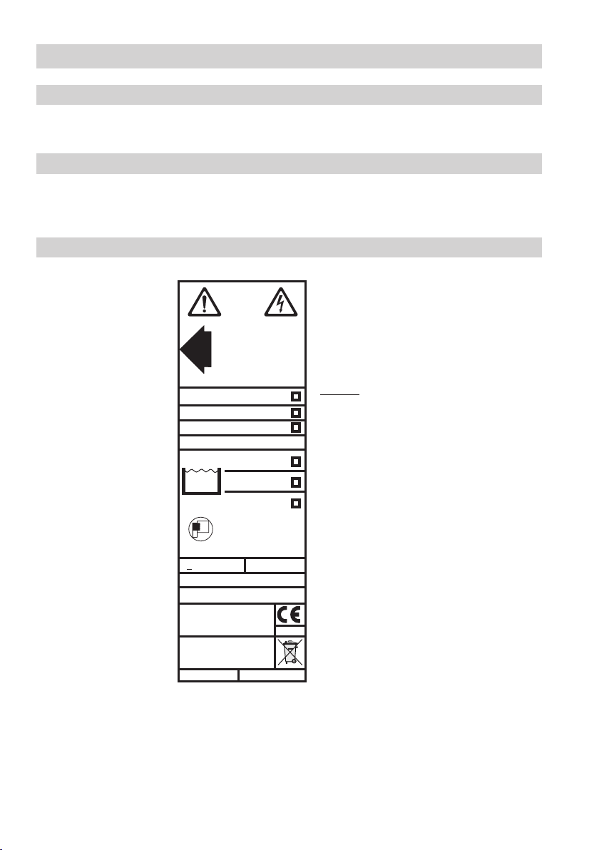
18-36 V DC0,5 µS/cm>
Betriebsanleitung
beachten!
See installation instructions!
Voir instructions de
montage!
Tmax = 70°C (158 °F)
IN/OUT: CAN-Bus
PN 63
PN160
PN 40
PmaxPmax
TmaxTmax
NRG 17-41
NRG 19-41
NRG 16-41
G 3/4 1.4571 IP65
60 bar (870psi)
275°C (527°F)
32 bar (464psi)
238°C (460°F)
100 bar (1450psi)
311°C (592°F)
Node ID: __ __ __
VS-Nr.: XX
Mat-Nr.: 392151
TÜV . SWB / SHWS .
02 - 403
0525
GESTRA AG
Münchener Str. 77
D-28215 Bremen
Corrosion resistance
When used for its intended purpose the safe functioning of the electrode will not be impaired by
corrosion.
Sizing
The electrode body is nor designed for pulsating loads. Welds and flanges of the electrode are designed to withstand dynamic loading (bending and alternating stress). The dimensional allowances for
corrosion reflect the latest state of technology.
Name plate / Marking
Designation of
the equipment
Fig. 1
8
Page 9
GESTRASt eamSystems
GESTRA
NRG 1...-41
MAX
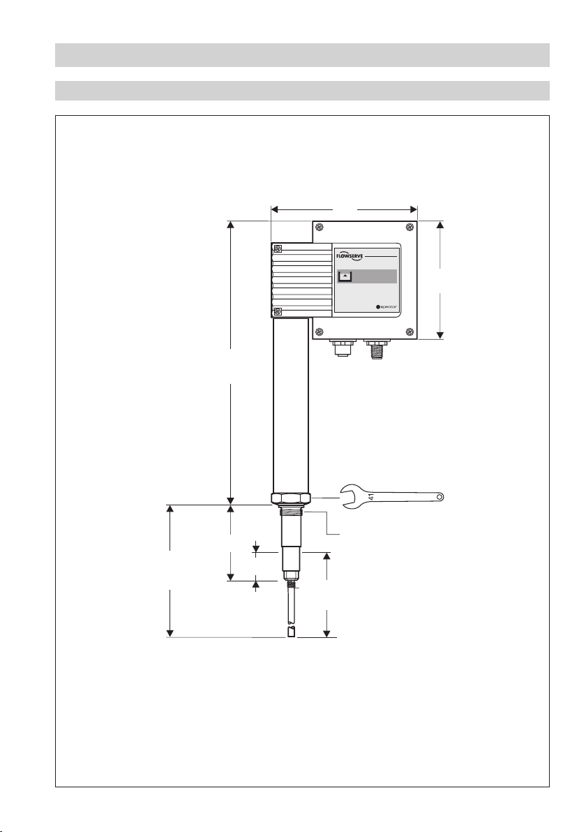
Technical Data continued
Dimensions NRG 16-41, NRG 17-41
175
140
337.5
F.
mm
A.
≥ 185
Fig. 2
50
¾" BSP, EN ISO 228-1
30
1500,
1000,
1500
9
Page 10

GESTRASte amSystems
GESTRA
NRG 1...-41
MAX
Technical Data continued
Dimensions NRG 19-41
175
140
≥ 185
Fig. 3
1500,
337.5
55
1000,
1500
F.
mm
A.
¾" BSP, EN ISO 228-1
30
10
Page 11

Design
NRG 16-41, NRG 17-41, NRG 19-41
S
Fig. 4
A
B
C
D
E
Fig. 5
F
∅ 33
¾" BSP,
EN ISO 228-1
N 8
G
N 10
0.5
Fig. 6
Fig. 7
11
Page 12

K
H
11
22
3
3
1
2 3 5 6 74
8
9
10
ON
1
2
3
4
5
LW HW
GESTRA Steam Systems
GESTRA
NRG 1...-41
MAX
MAX 70°C
MAX 95%
%
IP 65
Functional Elements
NRG 16-41, NRG 17-41, NRG 19-41
MAX 70 °C
MAX 95 %
12
Fig. 8
Fig. 9
R
H
IJI
K
L
M
N O
Q
P
Page 13

Design / Functional Elements continued
Key
A Electrode rod
B Bore
C Spring
D Electrode tip
E S. S. joint ring D 27 x 32 mm to DIN 7603 (made of 1.4301), bright annealed
F Seating surface
G Electrode thread
H Screws M 4
I M 12 sensor connector, 5 poles, A-coded, M 12 sensor jack, 5 poles, A-coded
J Cover
K Green LED “Program running”
L Green LED “Program running”
M 10-pole code selector for setting node ID and baud rate
N Red LED “CAN bus communication”
O Green LED “CAN bus communication”
P Terminal strip
Q PE connection
R Plug
S Thermal insulation (provided on site), d = 20 mm (outside of thermal insulation of steam
generating unit)
13
Page 14

Installation
NRG 16-41, NRG 17-41, NRG 19-41, step 1
1. Screw electrode tip
D into measuring electrode A , Fig. 4.
2. Carefully determine required measuring length of electrode. Observe min. length, Fig. 2, Fig. 3.
3. Mark length of electrode tip
4. Unscrew electrode tip
5. After visual inspection screw electrode tip
D.
D from measuring electrode A and cut tip.
D into measuring electrode A. Slide spring C along
electrode tip D, so that its end completely enters into small bore B.
NRG 16-41, NRG 17-41, NRG 19-41, step 2
1. Check seating surfaces, Fig. 6
2. Place ring joint E supplied with electrode onto seating surface F of electrode, Fig. 5
®
3. Apply a light smear of silicone grease (e.g. Molykote
4. Screw level electrode into threads of flange provided on vessel and tighten with
a 41 mm open end spanner. The torque required is 160 Nm when cold
5. When installing two electrodes together in one flange install the first electrode as described in 4.
111) to electrode thread G.
.
Before mounting the second electrode undo plug R, remove PE connection Q and strip cable lugs
from the board. Screw in electrode. Slightly tighten plug R. Install PE connection Q and insert
cable lugs.
Attention
■ The seating surfaces of the standpipe or the flange provided on the vessel must be
accurately machined, see Fig. 7.
■ Do not bend electrode tip when mounting.
■ Use only ring joint (of stainless steel 1.4301) D 27 x 32 to DIN 7603 supplied with
the electrode.
■ Do not lag electrode body above the hexagonal section, Fig. 5.
■ Do not insulate electrode thread with hemp or PTFE tape.
■ Do not screw electrode directly into a screwed socket, Fig. 6.
■ Observe min. spacing when installing the electrode, Fig. 6, Fig. 10, Fig. 11, Fig. 12
Note
■ For the approval of the boiler standpipe the relevant regulations must be considered.
■ Refer to page 15 for three typical installation examples.
Tools
■ Open-end spanner A. F. 17 mm
■ Open-end spanner A. F. 41 mm
Molykote® 111 is a registered trademark of DOW Corning Corp., Midland Michigan, USA
■ Hacksaw
■ Flat file, medium cut
14
Page 15

12
Installation continued
Examples of installation NRG 16-41, NRG 17-41, NRG 19-41
¾" BSP
1
DN 50
2
Fig. 10
3
4
8
∅ 20
3
20
5
6
9
≤ 90°
∅ 20
0
¾" BSP
1
1" BSP
¾" BSP
1
2
DN 20
≥ 20
4
DN 100
24.5 24.5
∅ 20
20
4
≤ 3000
5
7
8
4
ME
5
Fig. 11
≤ 90°
∅ 20
≥10
9
!
DN 20
Fig. 12
9
DN 20
15
Page 16

Installation continued
Key
1 Flange PN 40, DN 50, DIN 2527
Flange PN 40, DN 100, DIN 2527
2 For the approval of the boiler standpipe with connecting flange the relevant regulations
must be considered.
3 Vent hole (Provide vent hole as close to the boiler wall as possible)
4 High water level (HW)
5 Electrode rod d = 5 mm
6 Protection tube DN 80
7 Protection tube DN 100
8 Electrode distance ≥ 14 mm
9 Low water level
0 Reducer DIN 2616-2, K-88.9 x 3.2 - 42.4 x 2.6 W!
! Reducer DIN 2616-2, K-114.3 x 3.6- 48.3 x 2.9 W
16
Page 17

Wiring
NRG 16-41, NRG 17-41, NRG 19-41
Note that screened multi-core twisted-pair control cable is required for the BUS line, e. g. UNITRONIC®
BUS CAN 2 x 2 x ... mm
2
or RE-2YCYV-fl 2 x 2 x ... mm2.
Prefabricated control cables (with connector and coupler) of various lengths for connecting the
equipment are available as accessories.
The baud rate (data transfer rate) dictates the cable length between the bus nodes and the total power
consumption of the sensor dictates the conductor size.
S 8 S 9 S 10 Baud rate Cable length
OFF ON OFF 250 kBit/s 125 m
Factory setting
ON ON OFF 125 kBit/s 250 m 2 x 2 x 0.5
OFF OFF ON 100 kBit/s 335 m 2 x 2 x 0.75
ON OFF ON 50 kBit/s 500 m
OFF ON ON 20 kBit/s 1000 m
ON ON ON 10 kBit/s 1000 m
Number of pairs
and conductor size [mm2]
2 x 2 x 0.34
on request, dependent on
bus configuration
The baud rate is set via a code switch. Reduce baud if cable is longer than specified in the table. Make
sure that all bus nodes have the same settings.
To protect the switching contacts fuse circuit with 2.5 A (anti-surge fuse) or according to TRD
regulations (1.0 A for 72 hrs operation).
If a max. cable length of more than 125 m (up to 1000 m) is desired, make sure to modify the
baud rate settings accordingly. Please refer to pages 21 and 22.
Aligning terminal box
1. Undo screws H and remove housing cover J. Fig. 8
2. Slacken plug O with 17 mm open-end spanner but do not remove. Fig. 9
The electrode terminal box can now be turned through +/– 180°.
3. Turn electrode terminal box into desired position (+/–180°).
4. Tighten plug
O with 25 Nm.
5. Set node ID (see sections “Basic Settings” and “Factory set default node IDs”).
6. Re-attach housing cover J and fix it by using screws H.
Note
■ Wire the control cable according to the wiring diagram with connector and coupling.
UNITRONIC® is a registered trademark of LAPP Kabelwerke GmbH, Stuttgart
17
Page 18

1
NRG 1...-41
HW
_
1
2
3
4
5
C
L
S
C
H
+
C
L
H
C
2
3
24V DC
CAN - Bus
S
1
2 3 5 6 74
8
9
10
ON
Wiring continued
5 5 5 555
+
-
LCH
C
S
Wiring diagram
Electrode rod
Electrode rod
Electrode rod
Terminating resistor 120 Ω, twisted pair cable.
3
2 1 5 46 3 4 1 5 2
Code switch
e. g. UNITRONIC® BUS CAN 2 x 2 x...
e. g. UNITRONIC® BUS CAN 2 x 2 x...
1 Screen
2 Voltage supply 24V DC+
3 Voltage supply 24V DC-
4 CAN Data line C
5 CAN Data line C
6 Terminating resistor 120 Ω
2
2
H
L
Controller
NRS ...
LRR ...
TRS ...
Operating
device URB 1
CEP
Central
earthing
point
Coupler with terminating
resistor 120
Fig. 13
UNITRONIC® is a registered trademark of LAPP Kabelwerke GmbH, Stuttgart
Ω
18
Level electrode
Conductivity electrode
NRG ...
LRG ...
Temperature transmitter
TRV ...
Connector with terminating
resistor 120
Ω
Page 19

Wiring continued
Attention
■ Wire equipment in series. Star-type wiring is not permitted.
■ Interlink screens of control cables such that electrical continuity is ensured and
connect them once to the central earthing point (CEP).
■ The first and last equipment of a CAN bus network must be provided with a
terminating resistor of 120
■ The CAN bus network must not be interrupted while operating.
An interruption will result in high/low level alarm!
Tools
■ Screwdriver for cross head screws, size 1
■ Screwdriver for slotted screws, size 2.5, completely insulated according to VDE 0680
■ Open-end spanner 17 mm A. F.
Ω. Fig. 13
19
Page 20

Basic Settings
CAN bus
All level and conductivity controllers and associated electrodes are interconnected by means of a CAN
bus adopting the CANopen protocol. Every item of equipment features an electronic address (Node ID).
The four-core bus cable serves as power supply and data highway for high-speed data exchange.
The CAN address (Node ID) can be set between 1 and 123.
The equipment is configured at our works and ready for service with other GESTRA system
components without having to set the node ID.
If several systems of the same kind are to communicate in one CAN bus network, be sure to
assign one node ID for each individual system component (e. g. controller). Refer to the
following pages for more details.
Node ID
NRS 1-41 NRG 16-41 Reserved Reserved Reserved
X X + 1 X + 2 X + 3 X + 4
6 7 Factory setting
Reserved area
Attention
The node IDs of the respective devices must be set manually.
Refer to the installation & operating manual of the equipment in question.
Factory set default values
The level electrode features the following factory set default values:
■ Baud rate: 250 kB/s
■ Sensitivity: 0.5 µS/cm
■Node ID: 007
20
Page 21

Basic Settings continued
H
11
22
3
3
1
2 3 5 6 74
8
9
10
ON
1
2
3
4
5
LW HW
NRS 1-40 ID: 001
NRS 1-40.1 ID: 001
NRS 1-41 ID: 006
NRS 1-42 ID: 020
NRS 2-40 ID: 039
NRR 2-40 ID: 040
LRR 1-40 ID: 050
NRG 16-40 ID: 002
NRG 16-40 ID: 003
NRG 16-41.1 ID: 004
TRV 5-40 ID: 005
NRG 16-41 ID: 007
NRG 16-42 ID: 021
NRG 26-40 ID: 041
LRG 16-40 ID: 051
Factory set default node IDs
Switching Controller Level Electrode
Assigning / changing node ID
If several systems of the same kind are to communicate in one CAN bus network, be sure to assign
one node ID for each individual system component (e. g. controller).
1. Undo and remove screws
2. Set code switch
M to the required position. Please observe the setting tables on page 22.
3. Mount housing cover
Attention
■ Do not assign the same node ID twice within the CAN bus network.
H. Remove housing cover J.
J and tighten screws H.
Fig. 14
M
21
Page 22

1
2 3 5 6 74
8
9
10
ON
1
2 3 5 6 74
8
9
10
ON
Basic Settings continued
Setting code switch
M M
▲
S1
ON
ONS2
ONS3
OFFS4
OFFS5
OFFS6
OFFS7
Fig. 15 (Factory setting)
S8
OFF
ON
OFF
ON
ON
OFF
OFF
Node ID
S9 S0
OFFON
OFF
ON
ON
1
2
4
8
16
32
64
Baud rate
250 kBit/s
125 kBit/s
100 kBit/s
50 kBit/s
ON 20 kBit/sONOFF 1000 m
ON 10 kBit/sONON 1000 m
Fig. 17 (Factory setting 250 kBit/s)
7
▲
S1
OFFS4
OFFS5
OFFS6
Fig. 16 (Example)
ON
ONS2
ONS3
ONS7
Node ID
1
2
4
8
16
32
64
71
Length of cable
125 m
250 m
335 m
500 m
22
Page 23

Commissioning Procedure
Check wiring
Make sure that the level electrode NRG 1..-41 is properly connected to the switching controller
NRS 1-41 according to the wiring diagram, Fig. 13.
Apply mains voltage
Apply power to switching controller NRS 1-41.
Operation
High-water level limiter (Max alarm)
Used in combination with switching controller NRS 1-41 in (pressurized) hot-water plants and steam
boilers working in accordance with TRD 401, TRD 602, TRD 604 or other national regulations.
Note
■ Should malfunctions occur during the commissioning procedure refer to section
“Troubleshooting” on page 22 in order to find, analyse and eliminate the fault.
23
Page 24

Malfunctions
Fault finding list for troubleshooting
Equipment fails to work – Indication of a malfunction
Fault: In spite of correct wiring and commissioning of the equipment an interference signal
is indicated.
Remedy: The interference signal is caused by H. F. interferences coming from the installation.
For interference suppression of the voltage supply we supply ferrite rings, stock code
147253. The 230 V supply lines should be looped through the ferrite ring five to ten
times. If several controllers are used in the system, they can be fed from the interference
suppressed supply lines. For the interference suppression of the bus line we supply
hinged-shell ferrite rings, stock code 147254. The hinged-shell ferrite rings are clamped
onto the bus line close to the terminal strip of the controller.
Level electrode exposed – High-level alarm
Fault: Mains voltage not applied.
Remedy: Apply mains voltage. Connect electrode according to wiring diagram.
Fault: Thermal fuse has been triggered.
Remedy: The ambient temperature must not exceed 70 °C.
Fault: The electrode housing does not have earth connection to the boiler.
Remedy: Clean seating surfaces and insert metal joint ring (of stainless steel 1.4301) D 27 x 32
to DIN 7603. Do not insulate level electrode with hemp or PTFE tape.
Fault: No data exchange with CAN bus.
Remedy: Check switching controller NRS 1-41. Connect level electrode according
to wiring diagram.
Fault: The internal insulation of the electrode rod is damaged.
Remedy: Replace level electrode.
High water level reached – no function
Fault: The electrode rods have earth contact.
Remedy: Change installation position.
Fault: The vent hole in the protection tube does not exist, is obstructed or flooded.
Remedy: Check protection tube and, if necessary, provide vent hole.
Fault: The isolating valves of the external measuring pot (optional item) are closed.
Remedy: Open isolating valves.
If faults occur that are not listed above or cannot be corrected, please contact our service centre or
authorized agency in your country.
24
Page 25

Annex
Declaration of conformity
We hereby declare that the equipment NRG 16-41, NRG 17-41 and NRG 19-41 conforms to the
following European guidelines:
■
LV guideline 73/23/eec version 93/68/eec
■
EMC Directive 89/336/eec version 93/68/eec
■ ATEX Directive 94/9/EC of 23 March 1994
This declaration is no longer valid if modifications are made to the equipment without consultation
with us.
Bremen, 3rd January 2005
GESTRA AG
Dipl.-Ing. Uwe Bledschun
(Academically qualified engineer)
Head of the Design Dept.
Dipl.-Ing. Lars Bohl
(Academically qualified engineer)
Quality Assurance Manager
25
Page 26

For your notes
26
Page 27

For your notes
27
Page 28

Agencies all over the world:
www.gestra.de
GESTRA
España
GESTRA ESPAÑOLA S.A.
Luis Cabrera, 86-88
E-28002 Madrid
Tel. 00 34 91 / 5 15 20 32
Fax 00 34 91 / 4 13 67 47; 5 15 20 36
E-mail: aromero@flowserve.com
Great Britain
Flowserve Flow Control (UK) Ltd.
Burrel Road, Haywards Heath
West Sussex RH 16 1TL
Tel. 00 44 14 44 / 31 44 00
Fax 00 44 14 44 / 31 45 57
E-mail: gestraukinfo@flowserve.com
Italia
Flowserve S.p.A.
Flow Control Division
Via Prealpi, 30
l-20032 Cormano (MI)
Tel. 00 39 02 / 66 32 51
Fax 00 39 02 / 66 32 55 60
E-mail: infoitaly@flowserve.com
Polska
GESTRA POLONIA Spolka z.o.o.
Ul. Schuberta 104
PL - 80-172 Gdansk
Tel. 00 48 58 / 3 06 10 -02 od 10
Fax 00 48 58 / 3 06 33 00
E-mail: gestra@gestra.pl
Portugal
Flowserve Portuguesa, Lda.
Av. Dr. Antunes Guimarães, 1159
Porto 4100-082
Tel. 0 03 51 22 / 6 19 87 70
Fax 0 03 51 22 / 6 10 75 75
E-mail: jtavares@flowserve.com
USA
Flowserve GESTRA U.S.
2341 Ampere Drive
Louisville, KY 40299
Tel.: 00 15 02 / 4 95 01 54, 4 95 17 88
Fax: 00 15 02 / 4 95 16 08
E-mail: dgoodwin@flowserve.com
GESTRA AG
P. O. Box 10 54 60, D-28054 Bremen
Münchener Str. 77, D-28215 Bremen
Telephone +49 (0) 421 35 03 - 0
Fax +49 (0) 421 35 03 - 393
E-Mail gestra.ag@flowserve.com
Internet www.gestra.de
810743-01/206cm · © 2000 GESTRA AG · Bremen · Printed in Germany
28
 Loading...