

Page 1
Durametallic® LS-300 Series
Experience In Motion
Multiple lip seal cartridge for
high viscosity pumps
Installation
Instructions
Page 2
1 Equipment Check
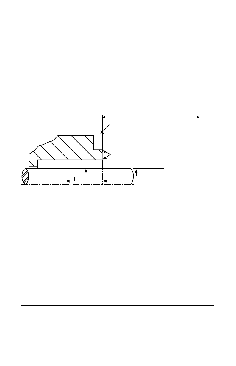
To first obstruction
Face of seal housing to be square to the axis
of the shaft to within 0.013 mm per millimeter
(0.0005 inches) of seal chamber bore FIM and
have a √1.6
μm (63 μinch) R finish or better
a
Gland pilot can be at either of these
register locations, concentric to within
0.13 mm (0.005 inch) FIM of shaft or sleeve OD
Sleeve or shaft finish to be
0.8 μm (32 μinch) R or better
a
Scribe
Mark A
Shaft or sleeve OD
+0.000 mm (+0.000 inch)
-0.050 mm (-0.002 inch) ANSI
+0.000 mm (+0.000 inch) API 610/682
-0.025 mm (-0.001 inch) DIN/ISO
• Bearings must be in good condition
• Maximum lateral or axial movement of shaft (end play) = 0.25 mm (0.010 inch) FIM
• Maximum shaft runout at face of seal housing = 0.05 mm (0.002 inch) FIM
• Maximum dynamic shaft deflection at seal housing = 0.05 mm (0.002 inch) FIM
Scribe
Mark B
Seal housing bore to have √3.2 μm
(125
μ
inch) R finish or better
a
1.1 Follow plant safety regulations prior to equipment disassembly:
• lock out motor and valves.
• wear designated personal safety equipment.
• relieve any pressure in system.
• consult plant MSDS les for hazardous material regulations.
1.2 Disassemble equipment to allow access to seal installation area.
1.3 Remove all burrs and sharp edges from the shaft or sleeve including sharp edges
of keyways and threads. Replace worn shaft or sleeve. Make sure the seal housing
bore and face are clean and free of burrs.
1.4 Check requirements for shaft, sleeve and seal housing, see Figure 1.
Seal Chamber Requirements Figure 1
1.5 Check assembly drawing included with the seal for specic seal design, materials
of construction, dimensions, and piping connections.
1.6 Check shaft or sleeve OD, box bore, box depth, and distance to the rst
obstruction to ensure that they are dimensionally the same as shown on the seal
assembly drawing.
1.7 Check gland pilot and bolt holes to ensure they are adaptable to the equipment
and are the same as shown on the assembly drawing. Many cartridge Flowserve
seal designs include centering tabs, eccentric washers, or centering plates that do
not require a gland pilot.
1.8 Handle all seal parts with care, they are manufactured to precise tolerances.
2 Cartridge Flowserve Seal Installation
2.1 Lubricate the shaft or sleeve lightly with silicone lubricant provided with the seal
before installing any seal parts.
2.2 Install the complete cartridge Flowserve seal assembly on the shaft and position
it close to the bearing housing with the seal orientated toward the pump.
2
The images of parts shown in these instructions may differ visually from the actual
parts due to manufacturing processes that do not affect the part function or quality.
Page 3
2.3 Position the cartridge gland against the seal chamber face and tighten
the gland stud nuts up evenly, cross staggering the adjustment of the nuts. Do not
over tighten the gland nuts.
2.4 Adjust the bearings, coupling, and impeller so that the shaft is in its operating
axial position. Any subsequent axial adjustment of the shaft requires resetting of
the seal.
2.5 Tighten the set screws in the seal cartridge collar to the shaft.
Suggested minimum torque values for the set screws are as follows:
Alloy C-276 or 316 SS Torque Value
#10 - 24 UNC 2.3 N-m (20 inch-lbs)
1/4" - 20 UNC 5.0 N-m (45 inch-lbs)
5/16" - 18 UNC 9.0 N-m (80 inch-lbs)
Alloy Steel, Plated Torque Value
#10 - 24 UNC 3.5 N-m (30 inch-lbs)
1/4" - 20 UNC 9.0 N-m (80 inch-lbs)
5/16" - 18 UNC 118.0 N-m (60 inch-lbs)
2.6 Remove the setting devices from the cartridge sleeve collar. These setting devices
should be saved and reinstalled for seal removal and repair or for repositioning the
pumps impeller.
Eccentric washers or rectangular style setting devices can be repositioned clear of
moving parts and locked in place on the gland for storage. These should be returned
to the setting position for seal removal and repair or for repositioning the pump impeller.
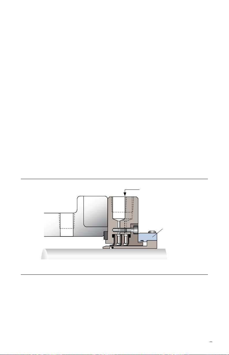
LS-300
Standard Barrier Ports for
Optional Leak Detection or
External Fluid Barrier
Setting
Device
3 Pipe Taps
3.1 The 1/4 inch pipe taps are dead-ended between the lips. One goes between the rst
and second lips and the other goes between the second and third lips. Most users
plug these ports.
These ports should be used if the product pumped polymerizes when sheared or
polymerizes when it contacts the air. In those instances a suitable solvent can be put
into the ports.
Caution: Very light solvents, as thin or thinner than water, may decrease the seal life.
For special problems encountered during installation, contact your nearest Flowserve Sales
and Service Representative or Authorized Distributor.
3
Page 4

TO REORDER REFER TO
flowserve.com
USA and Canada
Kalamazoo, Michigan USA
Telephone: 1 269 381 2650
Telefax: 1 269 382 8726
Europe, Middle East, Africa
Roosendaal, the Netherlands
Telephone: 31 165 581400
Telefax: 31 165 554590
Asia Pacific
Singapore
Telephone: 65 6544 6800
Telefax: 65 6214 0541
Latin America
Mexico City
Telephone: 52 55 5567 7170
Telefax: 52 55 5567 4224
B/M #
F.O
.
4 Repair
This product is a precision sealing device. The design and dimension tolerances are critical
to seal performance. Only parts supplied by Flowserve should be used to repair a seal. To
order replacement parts, refer to the part code and B/M number. A spare backup seal should
be stocked to reduce repair time.
When seals are returned to Flowserve for repair, decontaminate the seal assembly and
include an order marked "Repair or Replace." A signed certicate of decontamination
must be attached. A Material Safety Data Sheet (MSDS) must be enclosed for any
product that came in contact with the seal. The seal assembly will be inspected and, if
repairable, it will be rebuilt, tested, and returned.
FIS118eng 08/12 Printed in USA
To find your local Flowserve representative
and find out more about Flowserve Corporation,
visit www.flowserve.com
Flowserve Corporation has established industry leadership in the design and manufacture of its products. When
properly selected, this Flowserve product is designed to perform its intended function safely during its useful life.
However, the purchaser or user of Flowserve products should be aware that Flowserve products might be used
in numerous applications under a wide variety of industrial service conditions. Although Flowserve can provide
general guidelines, it cannot provide specific data and warnings for all possible applications. The purchaser/user
must therefore assume the ultimate responsibility for the proper sizing and selection, installation, operation, and
maintenance of Flowserve products. The purchaser/user should read and understand the Installation Instructions
included with the product, and train its employees and contractors in the safe use of Flowserve products in connection
with the specific application.
While the information and specifications contained in this literature are believed to be accurate, they are supplied for
informative purposes only and should not be considered certified or as a guarantee of satisfactory results by reliance
thereon. Nothing contained herein is to be construed as a warranty or guarantee, express or implied, regarding any
matter with respect to this product. Because Flowserve is continually improving and upgrading its product design,
the specifications, dimensions and information contained herein are subject to change without notice. Should any
question arise concerning these provisions, the purchaser/user should contact Flowserve Corporation at any one of
its worldwide operations or offices.
© 2012 Flowserve Corporation
 Loading...