


FISHER & PAYKEL DE60FA1, DE60FA-US User Manual

Use and Care
With Installation Instructions
RECYCLED PAPER
RECYCLABLE
We care about our environment
500A277P046
Downloaded from www.Manualslib.com manuals search engine

Safety Instructions................... |
3, 4 |
Installation Instructions |
|
Exhaust......................................................... |
6, 7 |
Electric Dryer ................................................... |
8 |
Gas Dryer ..................................................... |
8, 9 |
Reversible Door Instructions ....................... |
5 |
Care and Cleaning |
|
Dryer Exhaust ............................................... |
14 |
Exterior ........................................................... |
11 |
Light Bulb Replacement............................. |
13 |
Lint Filter ........................................................ |
11 |
Problem Solver ............................. |
15 |
|
|
Operating Instructions, Tips |
|
|
|
Consumer Services |
|
|
|
|
Automatic Drying |
13 |
|
|
|
Model and Serial Numbers |
2 |
|
|
|||||||
|
|
|
|
|
||||
|
|
Drying Selection Guide....................... |
12, 13 |
|
|
|
Repair Service ................................................. |
2 |
|
|
Electronic Sensor Control.......................... |
13 |
|
|
|
Warranty ........................................................ |
16 |
|
|
Extra Care Program |
10, 12 |
|
|
|
|
|
|
|
|
|
|
|
|
||
|
|
Knits Drying Tips .................................. |
11, 12 |
|
|
|
|
|
|
|
Lint Filter ........................................................ |
11 |
|
|
|
|
|
|
|
Loading ................................................... |
11, 15 |
|
|
|
|
|
|
|
Operating the Dryer.............. |
10, 11, 12, 13 |
|
|
|
|
|
|
|
Permanent Press |
|
|
|
|
|
|
|
|
Drying Tips ......................................... |
11, 15 |
|
|
|
|
|
|
|
Sorting Clothes ..................................... |
11, 12 |
|
|
|
|
|
|
|
Special Instructions..................................... |
12 |
|
|
|
|
|
|
|
Timed Drying......................................... |
12, 13 |
|
|
|
|
|
|
|
End Cycle Signal .......................................... |
10 |
|
|
|
|
|
|
|
|
|
|
|
|
|
|
|
|
|
|
|
|
|
|
|
Read this book carefully.
It is intended to help you operate and maintain your new dryer properly.
Keep it handy for answers to your questions.
If you don’t understand something or need more help, write (include your phone number)
Consumer Relations Manager Camco Inc.
1 Factory Lane, Suite 310
Moncton, N.B. E1C 9M3
Save time and money.
Before you request service...
check the Problem Solver section, it lists causes of minor operating problems that you can correct yourself.
If you received a damaged dryer...
Immediately contact the dealer (or builder) that sold you the dryer.
Write down the model and serial numbers.
You’ll find them on a label on the front of the dryer behind the door.
These numbers are also on the Consumer Product Ownership Registration Card that came with your dryer. Before sending in this card, please write these numbers here:
Model Number
Serial Number
Use these numbers in any correspondence or service calls concerning your dryer.
WARNING: For your safety the information in this manual must be followed to minimize the risk of fire or explosion or to prevent property damage, personal injury or death.
–Do not store or use gasoline or other flammable vapors and liquids in the vicinity of this or any other appliance.
–WHAT TO DO IF YOU SMELL GAS
•Do not try to light any appliance.
•Do not touch any electrical switch;
do not use any phone in your building.
•Clear the room, building or area of all occupants.
•Immediately call your gas supplier from a neighbor’s phone. Follow the gas supplier’s instructions.
•If you cannot reach your gas supplier, call the fire department.
–Installation and service must be performed by a qualified installer, service agency, or the gas supplier.
2
Downloaded from www.Manualslib.com manuals search engine

IMPORTANT SAFETY INSTRUCTIONS
Read all instructions before using this appliance
Warning - It is extremely important that you read and adhere to the following instructions. Failure to do so could cause bodily injuries and / or property damage due to fire.
•Use this appliance only for its intended purpose as described in this Use and Care Book.
This dryer must be properly installed and located in accordance with the Installation Instructions before it is used.
–Properly ground to conform with Local Codes. Follow details in Installation Instructions.
–Locate where the temperature is above 50˚F. (10˚C.) for satisfactory operation of the dryer control system. Do not install or store the dryer where it will be exposed to the weather.
–Connect to a properly rated, protected and sized power supply circuit to avoid electrical overload.
–Exhausting to the outside is STRONGLY RECOMMENDED to prevent large amounts of moisture and lint from being blown into the room. Carefully follow the Exhausting Details in the Installation Instructions.
Do not repair or replace any part of the
appliance or attempt any servicing unless specifically recommended in this
Use and Care Book or in published user-repair instructions that you understand and have the skills to carry out.
When disconnecting this appliance
pull by the plug rather than the cord to avoid damage to the cord or junction of cord and plug. Make sure that the cord
is located so that it will not be stepped on, tripped over or otherwise subjected to damage or stress.
To Minimize the Possibility of a
Fire Hazard
•Exhaust Duct – See Installation Instructions. Use only rigid metal or flexible metal 4” diameter ductwork for exhausting to the outside. USE OF PLASTIC OR OTHER COMBUSTIBLE DUCTWORK CAN CAUSE A FIRE. FOIL OR OTHER EASILY PUNCTURED DUCTWORK CAN CAUSE A FIRE IF IT COLLAPSES OR BECOMES OTHERWISE RESTRICTED IN USE OR DURING INSTALLATION.
•Do not use heat to dry articles containing rubber, plastic, or similar materials (such as padded bras, tennis shoes, galoshes, bath mats, rugs, bibs, pillows, baby pants, plastic bags, etc.) as these materials may melt or burn. Also, some rubber materials, when heated, can under certain circumstances produce fire by spontaneous combustion.
•Do not store items that may burn or melt (such as clothing, paper material, plastics or plastic containers, etc.) on top of the dryer during the operation.
•Garments labeled “Dry Away from Heat” (such as life jackets containing Kapok or foam) must not be put in your dryer.
• Do not wash or dry articles that
have been cleaned in, washed in,
soaked in, or spotted with combustible or explosive substances (such as wax, paint, gasoline degreasers, dry-
cleaning solvents, kerosene, etc.) which may ignite or explode. Do not add these substances to the wash water. Do not use these substances around your washer and/or dryer during operation.
•Any article on which you have used a cleaning solvent, or which contains flammable materials (such as cleaning cloths, mops, towels used in beauty salons, restaurants or barber shops, etc.) must not be placed in or near the dryer until all traces of these flammable liquids or solids and their fumes have been removed. There are many highly flammable items used in homes such as: acetone, denatured alcohol, gasoline, kerosene, some household cleaners, some spot removers, turpentines, waxes, wax removers and products containing petroleum distillates.
(continued on next page)
3
Downloaded from www.Manualslib.com manuals search engine
Instructions Safety Important

IMPORTANT SAFETY INSTRUCTIONS
 •Clean the lint filter before each load
to prevent lint accumulation inside
the dryer or in the room.
DO NOT OPERATE THE DRYER
WITHOUT THE LINT FILTER IN PLACE.
•Keep the area around and underneath your appliances free from the accumulation of combustible materials, such as lint, paper, rags, chemicals, etc.
•Regularly inspect the exhaust duct to be sure it has not been crushed or otherwise restricted.
•The interior of the dryer cabinet and the exhaust duct connection inside the dryer should be cleaned every 2 to 3 years, or more often if needed, by a qualified service person. (see Care & Cleaning section)
To Minimize the Possibility of Injury
•Never reach into the dryer while the drum is moving. Before loading, unloading or adding clothes, wait until the drum has completely stopped.
•Do not dry fiberglass articles in your dryer. Skin irritation could result from the remaining glass particles that may be picked up by clothing during subsequent dryer uses.
• The laundry process can reduce the flame retardance of fabrics. To avoid such a result, the garment manufacturer’s care instructions should be followed very carefully.
• Close supervision is necessary if this
appliance is used by or near children.
Do not allow children to play inside,
on, or with this appliance or any
discarded appliance. Dispose of discarded appliances and shipping or
packing materials properly. Before discarding a dryer, or removing from service, remove the door of the dryer compartment.
SAVE THESE
INSTRUCTIONS
4
• Keep all laundry aids (such as detergents, bleaches, fabric softeners, etc.) out of the reach of children, preferably in a locked cabinet. Observe all warnings on container labels to avoid personal injury.
•Keep the floor around your appliances clean and dry to reduce the possibility of slipping.
•To minimize the possibility of electric shock,
unplug this appliance from the power supply before attempting any maintenance or cleaning (except the removal and cleaning of the lint filter).
• NOTE: Turning the Cycle Selector knob to an OFF position does NOT disconnect the appliance from the power supply.
•Do not tamper with the controls.
•Do not operate this appliance if it is damaged, malfunctioning, partially disassembled, or has missing or broken parts, including a damaged cord or plug.
•Never climb on or stand on the dryer top.
•DO NOT place items exposed to cooking oils in your dryer. Items contaminated with cooking oils may contribute to a chemical reaction that could cause a clothes load to catch fire.
•If yours is a gas dryer, it is equipped with an automatic electric ignition and does not have a pilot light. DO NOT ATTEMPT TO LIGHT WITH A MATCH. Burns may result from having your hand in the vicinity of the burner when the automatic ignition may turn on.
Dryer-applied Fabric Softeners or Anti-static Conditioners
You may wish to soften your laundered fabrics or reduce the static electricity in them. We recommend you use either a fabric softener in the wash cycle, according to the manufacturer’s instructions for those products, or try a dryer-added product for which the manufacturer gives written assurance on the package that their product can be safely used in your dryer.
Service or performance problems caused by the use of these products are the responsibility of the manufacturers of those products and are not covered under the warranty of this appliance.
Downloaded from www.Manualslib.com manuals search engine
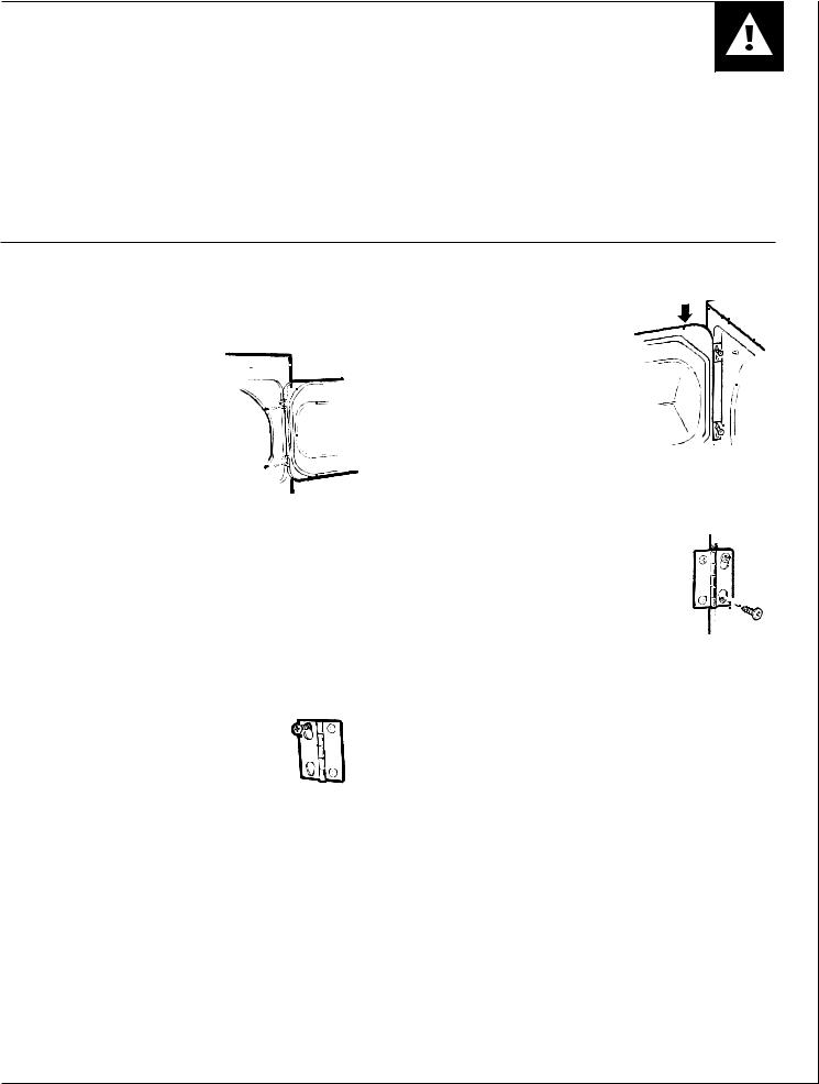
REVERSIBLE DOOR INSTRUCTIONS
These instructions are for changing the hinges from the |
If you need to change the hinges from the left side to |
right side to the left side. |
the right side, follow these same instructions (merely |
|
reverse all references to the left and right). |
|
|
Tools Needed
Standard #2 Phillips screwdriver
DRYER DOOR
1. Open the door and remove the filler plugs opposite the hinges.
(A tape-tipped putty knife or a needle-nosed plier will help to remove the plugs. Be careful not to damage the paint.)
2.With the door completely open, remove the bottom screw attaching each hinge to the dryer front. (Do not remove the screws located on the door itself).
3.Insert these screws about half way into the top holes, for each hinge, on the opposite side (where you removed the filler plugs).
4. Loosen the remaining top screw from each hinge on the dryer front, half way.
5. With one hand holding the top of the door, and the other hand holding the bottom, remove the door from the dryer front by lifting it UP and OUT.
6. Rotate the door 180˚. Insert it on the opposite door frame by moving the door IN and DOWN until the top hinge and the bottom hinge are resting on the top screws inserted in step 3.
7. With the other screws, secure each hinge at the bottom.
8. Tighten the top screws of each hinge.
9. Reinsert the plastic plugs on the side from which the door was removed.
5
Downloaded from www.Manualslib.com manuals search engine
Instructions Door Reversible

INSTALLATION INSTRUCTIONS
EXHAUST
Installation and service must be performed by a qualified installer, service agency or the gas supplier.
IMPORTANT: Have your dryer installed properly.
NOTE: The WARNING and IMPORTANT instructions appearing in this manual are not meant to cover all possible conditions and situations that may occur. It must be understood that common sense, caution, and carefulness are factors that CANNOT be built into the dryer. These factors MUST BE supplied by the person(s) installing, maintaining, or operating the dryer.
Failure to install, maintain, and/or operate this machine according to the manufacturer’s instructions may result in conditions which can produce bodily injury and/or property damage.
This dryer comes ready for rear exhausting (see Fig. 1).
WARNINGS
•DO NOT USE NON METALLIC FLEXIBLE DUCT.
•Never use flexible duct inside the dryer.
•Do not terminate exhaust in a chimney, range hood, gas vent, floor or attic. The combination of lint and grease could create a fire hazard or damages.
•Provide an access for inspection and cleaning the exhaust system at least once a year. (See Care and Cleaning Section.)
EXHAUST LENGTH
The MAXIMUM ALLOWABLE length of the exhaust system depends upon the type of duct, number of turns, the type of exhaust hood (wall cap), and all conditions noted below. The maximum allowable length for both rigid and flexible metal duct is shown in the table 1 (next page). More than four 90˚ turns is not recommended.
EXHAUST SYSTEM CHECK LIST HOOD or WALL CAP
TURNS OTHER THAN 90˚
•One turn of 45˚ or less may be ignored.
•Two 45˚ turns should be treated as one 90˚.
•Each turn over 45˚ should be treated as one 90˚.
SEALING OF JOINTS
•All joints should be tight to avoid leaks. The male end of each section of duct must point away from the dryer.
•Do not assemble the duct work with fasteners that extend into the duct. They will serve as a collection point for lint.
•Duct joints can be made air and moisture-tight by wrapping the overlapped joints with duct tape.
INSULATION
•Duct work which runs through an unheated area or is near an air conditioning duct, should be insulated to reduce condensation and lint build up and be sloped down toward outdoors.
NOTE: Never install screen inside exhaust duct.
•Terminate in a manner to prevent back drafts or entry of birds or other wildlife.
•Termination should present minimal resistance to the exhaust air flow and should require little or no maintenance to prevent clogging.
•Wall caps must be installed at least 300 mm (12”) above ground level or any other obstruction with the opening pointed down.
•If roof vents or louvered plenums are used, they must be equivalent to a 100 mm (4”) dampered wall cap in regard to resistance to air flow, prevention of back drafts and maintenance required to prevent clogging.
SEPARATION OF TURNS
Separate all turns by at least 1 m (3 ft.) of straight duct, including distance between last turn and dampered wall cap. If two turns must be closer than 1 m (3 ft.) deduct 3 m (10 ft.) from the maximum lengths shown in the table for each occurrence.
CAUTION: THE DRYER MUST EXHAUST TO THE OUTDOORS.
|
91mm |
|
(3 1/2") |
298mm |
NOTE: ADD TO |
91mm (31/2") |
|
(11 3/4") |
THE DISTANCE |
|
BETWEEN |
CABINET BOTTOM
TO FLOOR SURFACE
6
Downloaded from www.Manualslib.com manuals search engine
INSTALLATION INSTRUCTIONS
EXHAUST
Table 1: RECOMMENDED MAXIMUM LENGTH
ELECTRIC DRYERS |
GAS DRYERS |
||
|
|
||
Weather Hood Type |
Weather Hood Type |
||
|
|
|
|
Recommended |
Use only for short |
Recommended |
Use only for short |
|
run installations |
|
run installations |
No. of 90˚ |
Rigid |
Metallic |
Rigid |
Metallic |
Rigid |
Metallic |
Rigid |
Metallic |
elbows |
|
Flexible* |
|
Flexible* |
|
Flexible* |
|
Flexible* |
|
|
|
|
|
|
|
|
|
0 |
27.4 m (90 ft.) |
16.8 m (55 ft.) |
18.3 m (60 ft.) |
13.7 m (45 ft.) |
13.7 m (45 ft.) |
9.1 m (30 ft.) |
9.1 m (30 ft.) |
4.6 m (15 ft.) |
1 |
18.3 m (60 ft.) |
12.2 m (40 ft.) |
13.7 m (45 ft.) |
9.1 m (30 ft.) |
10.7 m (35 ft.) |
6.1 m (20 ft.) |
6.1 m (20 ft.) |
3.0 m (10 ft.) |
2 |
13.7 m (45 ft.) |
9.1 m (30 ft.) |
10.7 m ( 35 ft.) |
6.1 m (20 ft.) |
7.6 m (25 ft.) |
3.0 m (10 ft.) |
3.0 m (10 ft.) |
– |
3 |
10.7 m (35 ft.) |
6.1 m (20 ft.) |
7.6 m (25 ft.) |
4.6 m (15 ft.) |
4.6 m (15 ft.) |
– |
– |
– |
4 |
7.6 m (25 ft.) |
4.6 m (15 ft.) |
4.6 m (15 ft.) |
3.0 m (10 ft.) |
– |
– |
– |
– |
|
|
|
|
|
|
|
|
|
* Do not use non metallic flexible duct.
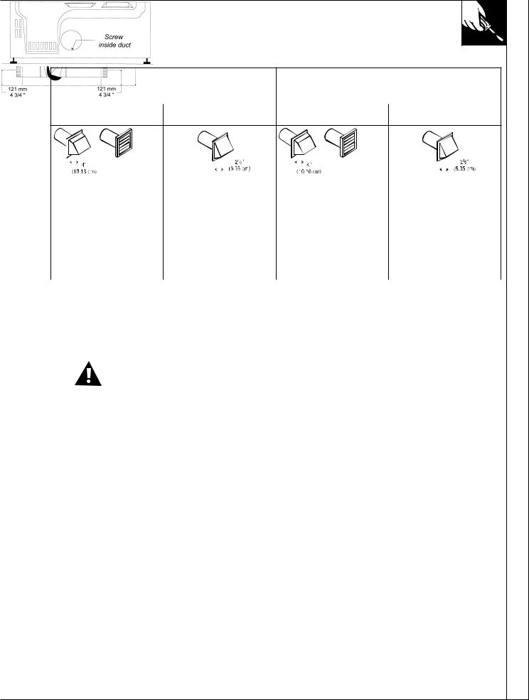
ALTERNATE EXHAUST DIRECTIONS
This dryer comes ready for rear exhausting. If space is limited, use the following instructions to exhaust directly from the side or bottom of the cabinet.
GAS DRYER CAN NOT BE EXHAUSTED DIRECTLY THROUGH THE RIGHT SIDE OF THE CABINET.
WARNING: Protect your hands and arms when working inside the cabinet.
•Never use flexible duct inside dryer.
•Detach and remove the desired knockout.
•Remove the screw inside the dryer exhaust duct end. Pull on the duct to remove it. Keep the screw for later.
•Cut the duct as shown, 229 mm (9 inches). Keep portion A.
•Through the rear opening, locate the tab in the middle of the appliance base. Lift the tab to about 45˚ using a flat screwdriver.
•Reconnect and secure the cut portion (A) of the duct to the blower housing. Make sure that the fixing hole is aligned with the tab in the base. Use the reserved screw to secure the duct in place through the tab on the appliance base.
•Use a standard and ajustable metal elbow and a metal straight duct to exhaust the dryer through the knockout choosen. Insert standard elbow and ducts through rear and side or bottom openings.
•Use only 100 mm (4 inch) diameter rigid metallic duct.
•Cover the opening at the back with the plate (Kit WE1M454) available from your Local Service Provider.
WARNING: Never leave the opening at the back |
7 |
without the plate. |
Downloaded from www.Manualslib.com manuals search engine
Instructions Installation
INSTALLATION
IMPORTANT - OBSERVE ALL GOVERNING CODES
Dryer must be levelled and rest firmly on the floor.
SPECIAL INSTALLATION REQUIREMENTS
ALCOVE OR CLOSET INSTALLATION
•The dryer MUST be exhausted to the outdoor. See EXHAUST INFORMATION section.
•Minimum clearances between dryer cabinet and adjacent walls or other surfaces are:
0 mm (0”) either side
76 mm (3”) front and rear
•Minimum vertical space from floor to overhead cabinets, ceilings, etc. is 132 cm (52”).
NOTE: CONSIDERATION MUST BE GIVEN TO INSTALLING AND SERVICING THE APPLIANCE.
•Closet door must be louvered or otherwise ventilated and must contain a minimum of 387 cm2 (60 in2) of open area equally distributed. If this closet contains both a washer and a dryer, doors must contain a minimum of 774 cm2 (120 in2) of open area equally distributed.
•If yours is a gas dryer, the closet should be vented to the outdoors to prevent gas pocketing in case of a gas leak in the supply line.
•No other fuel-burning appliance shall be installed in the same closet with the dryer.
MINIMUM CLEARANCES OTHER THAN ALCOVE OR CLOSET INSTALLATIONS.
•Minimum clearances to combustible surfaces and for air opening:
0 clearance both sides and 25 mm (1”) rear.
MOBILE HOME INSTALLATION
•The dryer must be exhausted to the outdoors with the termination securely fastened to the mobile home structure. (See EXHAUST INFORMATION section.)
•The exhaust MUST NOT be terminated beneath the mobile home.
•The exhaust MUST NOT be connected to any other duct, vent and chimney.
•Provisions must be made for the introduction of outside air into the dryer room. The free air opening shall not be less than 160 cm2 (25 in2).
•The exhaust duct material MUST BE METAL.
•Do not connect the exhaust duct with sheet metal screws or other fastening devices which extend to the interior of the duct.
•The dryer must be attached to the floor following instructions available from the dealer.
•Installation must comply with the current CAN/CSA Z240 MH series Mobile Home Installation Codes.
NOTE: CONSIDERATION MUST BE GIVEN TO INSTALLING AND SERVICING THE APPLIANCE.
LEVELING THE DRYER
Adjust all 4 leveling legs to match washer height. Dryer MUST BE LEVEL and rest firmly on all 4 leveling legs.
SIDE
VIEW
4LEVELING LEGS
DUCT LENGTH
For maximum performance, refer to table for maximum allowable length of exhaust system (Exhaust section).
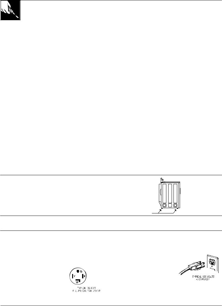
ELECTRICAL POWER SUPPLY
CAUTION: NEVER USE AN EXTENSION CORD WITH THIS APPLIANCE.
Note: If the electrical power supply provided does not meet the specifications listed below, call a licensed electrician.
FOR ELECTRIC DRYERS, POWER SUPPLY...
1.Must be of 120/240 volts or 120/208 volts, 60 Hz circuit with wall receptacle as
shown beside.
2.Must be protected with 30A FUSES OR BREAKERS.
3.Must be WELL GROUNDED.
4. Must CONFORM TO LOCAL CODES.
8
FOR GAS DRYERS, POWER SUPPLY...
1. Must be of 120 volts, 60 Hz
circuit with wall receptacle as shown beside.
2. Must be protected with 15 or
20A FUSES OR BREAKER.
3.Must be WELL GROUNDED.
4.Installation must be in accordance
with the current CSA C22.1 Canadian Electrical code part 1 and/or local codes.
Downloaded from www.Manualslib.com manuals search engine

INSTALLATION – GAS DRYER
IMPORTANT - OBSERVE ALL GOVERNING CODES
Dryer must be levelled and rest firmly on the floor. Dryer must be exhausted to the outdoors.
FOR YOUR SAFETY
What to do if you smell gas
•Do not try to light appliance.
•Do not touch any electrical switch ; do not use any phone in your building.
•Clear the room, building or area of all occupants.
•Immediately call your gas supplier from a neighbor’s phone. Follow the gas supplier’s instructions.
•If you can not reach your gas supplier, call fire department.
•Installation and service must be performed by a qualified installer, service agency, or the gas supplier.
FOR YOUR SAFETY Do not store or use gasoline or other flammable vapors and liquids in the vicinity of this or any other appliance.
GAS CONNECTION INFORMATION
Installation must conform with local Gas Codes and with CAN/CGA-B149, Natural Gas Installation Code.
Some local codes restrict installation of gas appliances in garages. They must be 45 cm (18”) off the ground and protected by a barrier from vehicules.
GAS BURNER ORIFICE
This gas dryer is equipped with a Valve & Burner Assembly for use ONLY WITH ONE TYPE OF GAS. Using the appropriate kit, your local service organization can convert this dryer for use with the alternate fuel.
Use kit WE25M35 to convert from Natural Gas to LP Gases (Propane).
Use kit WE25M36 to convert from LP Gases to Natural Gas.
WARNING: CONVERSION SHALL BE CARRIED OUT IN ACCORDANCE WITH THE REQUIREMENTS OF THE PROVINCIAL AUTHORITIES HAVING JURISDICTION AND/OR ACCORDANCE WITH THE REQUIREMENTS OF THE CAN/CGA B149.1 AND B149.2 INSTALLATION CODE.
MALE THREAD GAS SUPPLY |
9.52 mm (3/8") |
66 mm |
(2 5/8") |
51mm |
(2") |
GAS SUPPLY
•Supply line is to be 12.7 mm (1/2 in) rigid pipe. (9.53 mm (3/8 in) copper tubing may be used if the dryer is operated on propane gas) and equipped with an accessible shutoff within 6 feet (2 m) from, and in the same room with the dryer. Increase pipe size for runs longer than 20 feet (7 m).
•During pressure test:
–When test pressure is in excess of 1/2 PSIG (3.45kPa), disconnect dryer and its individual shutoff valve from gas supply line prior to test.
–When test pressure is equal to or less than 1/2 PSIG (3.45kPa), close the dryer shutoff valve prior to test.
•A 3.18 mm (1/8 in) National Pipe Taper thread plugged tapping, accessible for test gauge connection, must be installed immediately upstream of the gas supply connection to the dryer. Contact your local gas utility should you have questions on the installation of the plugged tapping.
•Pipe dope must be resistant to the action of propane and applied sparingly to all male threads.
•If local codes permit, it is recommended the dryer be connected to the gas supply with approved semi-rigid metal tubing or listed connectors.
LEAK TEST
Check all connections for leaks with soapy solution or equivalent. Leak test solutions must not contain ammonia which could cause damage to brass fittings or pipe.
CAUTION: NEVER USE AN OPEN FLAME TO TEST FOR GAS LEAKS.
9
Downloaded from www.Manualslib.com manuals search engine
Instructions Installation

OPERATING YOUR DRYER
WARNING – To reduce the risk of fire, electric shock, or injury to persons when using your appliance read the IMPORTANT SAFETY INSTRUCTIONS before operating this appliance.
1
Features and appearances may vary
1
Care selector for your load.
NOTE: Drying times will vary according to the type of heat used (Electric, Natural gas or LP gas), size of load, types of fabrics, wetness of clothes, and condition of
|
Should be used with cycles indicated |
||
|
|
|
|
Drying |
Automatic |
Automatic |
|
Selections |
Cottons |
Perm. Press |
Timed |
Cottons
High Heat
Perm. Press
Medium Heat
Knits/Delicates
Low Heat
Fluff
No Heat*
-No Heat option can be used with an automatic cycle, but for best it is recommended to be used with a timed cycle.
2Cycle Selector. Turn the Cycle Selector to the desired cycle setting. The selector may be turned in either direction.
3Press Guard Cycle. (Available on some models.) The Press Guard cycle operates only with the Automatic Permanent Press and Automatic Cottons cycles. Turn the Press Guard knob to SET or press the pad to select, and turn the Cycle Selector Dial to the desired amount of heated drying time.
10
3 |
4 |
2 |
setting in clothes, the Press Guard cycle provides from15 to 20 minutes of no-heat tumbling after the clothes are dry.
Used the End Cycle Signal to remind you to remove the dried laundry.
4End Cycle Signal. (Available on some models.)
Set End Cycle Signal, if desired. This signal operates with any cycle on some models. The control can be set anywhere between OFF and LOUD, depending on the desired sound level. The signal will start to sound just before the end of the cycle to remind you to remove the clothes. To stop the signal while sounding, turn the signal control to OFF or advance the Cycle Selector to OFF.
This signal should always be used when drying polyester knits or permanent press items which should be removed as soon as the dryer stops to help prevent setting of wrinkles.
If the signal is on and you choose the Press Guard cycle, you will hear the signal sound on and off throughout the cycle. This reminds you that the clothes
5are dry.
Start. Turn the Start knob or press the Push to Start button to start the dryer. (Opening the door during operation stops the dryer. To restart, close the door and follow above directions.)
Downloaded from www.Manualslib.com manuals search engine
 Loading...